2.1. Traditional Control of the da Vinci Surgical System
The surgeon console of the da Vinci system has two hand controllers called master tool manipulators (MTMs). They are used to manipulate both the instrument arms (called the patient-side manipulators, or PSMs) and the camera arm (called the endoscopic camera manipulator, or ECM). The da Vinci system can have up to three PSMs, and they are used to hold “EndoWrist” instruments, such as needle drivers, retractors, and energy-delivering instruments. On the other hand, the system has one ECM that is inserted with the PSMs inside the abdominal cavity to provide a 3D view of the worksite.
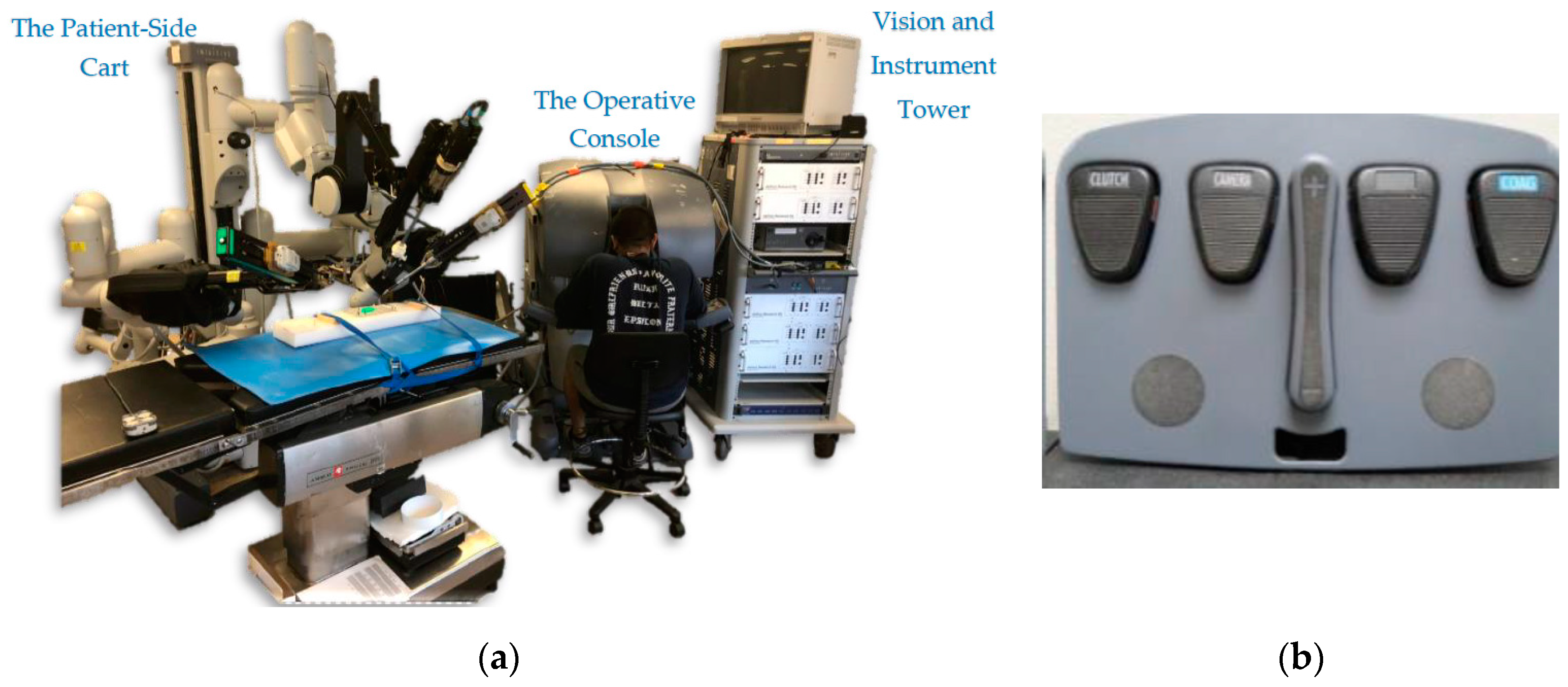
The surgeon uses the same hand controllers to control both the PSMs and ECM by using a foot clutching mechanism to change the control behavior of the MTMs (
Figure 1b). Once the surgeon presses the camera clutch on the foot tray, the PSMs lock their pose, and movement of the MTMs begins to control the ECM. The orientation of the MTMs is also frozen to match the orientation of the PSMs. As soon as the clutch is released, the MTMs can again be used to control the PSMs. Thus, the surgeon is not able to control the PSMs and the ECM simultaneously, and must pause the operation to adjust the camera view. This can be cumbersome.
There is even more intricacy involved with clutching that can add to the overall complexity. The other three clutches of the foot pedal tray are used to trigger different events. For example, the far-left clutch pedal is used to reposition the MTMs by dissociating them from controlling the PSMs or ECM. Note here that when this clutch is engaged, the orientation of the MTMs remains locked to match the orientation of the PSMs. The remaining two pedals are used to enable the surgeon to perform different tasks such as swapping between diverse types of instruments. The long, two-part button in the middle is used to control the focus of the camera. In summary, the surgeon interface is a complex system that includes multiple clutch controls, and MTM movements are clutch-mapped to control both the ECM and the PSMs.
2.4. The Cross-Operating-System Network Interface
Two different operating systems were used in our implementation. The HMD is only supported in Windows (due to driver restrictions), and the DVRK/ROS system only operates on Linux/Ubuntu (due to its ROS implementation). The Vive HMD was connected to a Windows PC and was programmed using the Unity environment. On the other hand, the ECM and the da Vinci control units were connected through the Ubuntu DVRK system running ROS. Due to ease of use and simplicity in the two environments, we are using two programming languages: C# to program in Unity on Windows and Python to program the ROS nodes on Ubuntu.
To connect the two sides together, we used socket communication between the two operating systems running on two different machines. The socket connection used the Transmission Control Protocol (TCP) to communicate between a server on Windows and a client on Ubuntu. The data (HMD pose) was sent from the server (Windows/Unity) to the client (Ubuntu/ROS).
The Ubuntu/ROS software executes a 3D simulation of the da Vinci system (including the camera arm). This can run independently of the hardware, and it enables simultaneous visualization and debugging. If needed, the simulator can run on a separate PC to minimize any performance impact.
Figure 6 shows the flow of data used to control the da Vinci ECM. As the surgeon moves the HMD with his/her head, software on the Windows PC uses Unity libraries to capture the position and orientation of the headset from its onboard sensors. In addition, the software also retrieves the camera images from both ECM cameras, processes them, and projects the camera views of the environment on the HMD screens. The pose of the HMD is then sent via a TCP connection to the Ubuntu machine (running the ROS nodes) to move the robot hardware. The HMD node subscribes to the HMD (HW) node that monitors the ECM’s current position (and can also move the hardware). The HMD node then publishes the desired position of the ECM to the ECM (HW) node. The low-level interface software, which subscribes to the ECM node and is directly connected to the hardware, moves the ECM accordingly. Simultaneously, the HMD node also publishes the desired ECM position to the ECM (Sim) node so the camera arm of the simulated robot (in RViz) moves accordingly.
2.4.1. HMD-Based Control
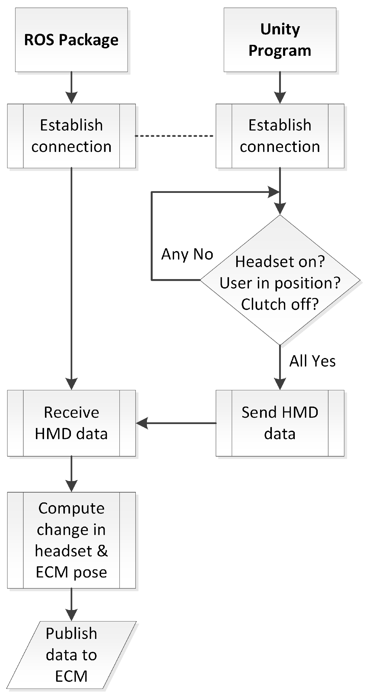
Figure 7 shows a flowchart of the HMD system software. The overall task is to capture HMD pose information and publish the required joint angles to the ECM hardware in order to match the HMD view and render the ECM camera views to the headset. The first step is to establish a TCP connection for transfer of pose data from the Unity project on the Windows machine (server) to the ROS nodes on the Ubuntu machine (client). Once the connection between the server and the client is established, two conditions should be met for ECM hardware to be activated as follows:
For additional safety, the session must be initiated by a person monitoring the system. Even if the system is ready to proceed, the default settings are set to the clutch-engaged setting to prevent the server from sending any data to the client/hardware. The human monitor of the system must activate the software to proceed. In a clinical system, this human monitor could be replaced by the surgeon engaging a foot pedal to activate the system. Additional redundant safety checks could be enabled, such as requiring an initiation step (e.g., closing and opening the grippers of the instrument arms).
In addition, the user can reposition his/her head by pressing the assigned button on the foot pedal tray. This is a repositioning/reclutching operation to allow the user to re-center himself. This is like lifting a mouse on a mousepad to pause a cursor or repositioning the MTMs by pressing the clutch button. The user depresses the button to dissociate the headset from controlling the ECM, repositions himself and then releases the button to regain to control of the ECM. Once the user is done with the operation, he/she could take the headset off and the proximity sensor will detect this move and pause the system. The final step is to disengage the system using the Unity interface.
2.4.2. Error Checking to Ensure Hardware Protection
When first donning the HMD for use, there is an initialization that aligns the HMD pose to the ECM pose. To avoid any sudden jumps during this initialization, a simple procedure in software was needed while the ECM adjusted to the position and orientation of the HMD. We created a function to map the ECM and HMD positions by first calculating the difference between the acquired ECM and the HMD positions. Then we added the offset (Delta) to the position values received from the HMD whenever we publish the HMD position to the ECM. Thus, any sudden movements related to initialization were prevented.
This also is a safety mechanism in case there are any sudden movements by the user. A computed delta value is applied whenever a sudden HMD movement (greater than 0.02 rad at a software timing loop of 0.01 s, or 2 rad/s) is performed by the user; when the new computed ECM angular motion is greater than a specified threshold (0.02 rad), a new delta is computed and applied. This value is less than the maximum allowable delta of the ECM (0.05 rad), which is specified in the FireWire controller package developed by Johns Hopkins to protect the hardware. This value is also large enough to accommodate typical head movements. Recalculating the value of delta using the new difference between the poses of the ECM and the HMD when the speed exceeds 2 rad/s prevents the ECM from responding with dangerous, hardware-damaging quick movements. This same mechanism is used for head repositioning when the user presses the foot pedal assigned for the HMD system and moves his/her head to re-center. After repositioning the head, releasing the food pedal creates an offset (bigger than 0.02 rad) which triggers the function to recalculate the delta value and map the ECM and HMD poses. The simplified pseudocode shown in
Figure 9 illustrates how the measured head motion is used to control the ECM.
To enhance surgical dexterity and accuracy, the da Vinci System offers an adjustable motion scaling of 1:1, 2:1, and 3:1 between the MTMs and the PSMs. We implemented the same concept between the HMD and the ECM to have a motion scaling of 2:1. With this value, we tried to map/match the user’s hand speed with the head motion. The motion scaling also prevented fast ECM movements, which cause shaking and instability in the ECM hardware. More studies can be performed to optimize the HMD–ECM motion scaling ratio.
2.5. Human Participant Usability Testing
To show the usability of this system on an actual task, an initial 6-subject study was conducted. Six subjects (ranging in age from 23 to 33) were recruited from the student population at Wayne State University in accordance with an approved IRB (Institutional Review Board) for this study. The aim of the study was simply to show that the system is usable and to get some initial objective and subjective feedback from the participants. We prepared a checklist of the essential information/details that the participants should be aware of before starting the study. The same checklist was reviewed by and explained to all the subjects. For instance, this checklist involved explaining the different parts of the system, understanding the usage of the foot pedal tray and the tool-repositioning technique, and explaining the task. After the introduction, the participants performed the same training for both HMD control and clutched camera control method on a practice task pattern. In this way, we ensured that the subject was at the same level of experience in both methods.
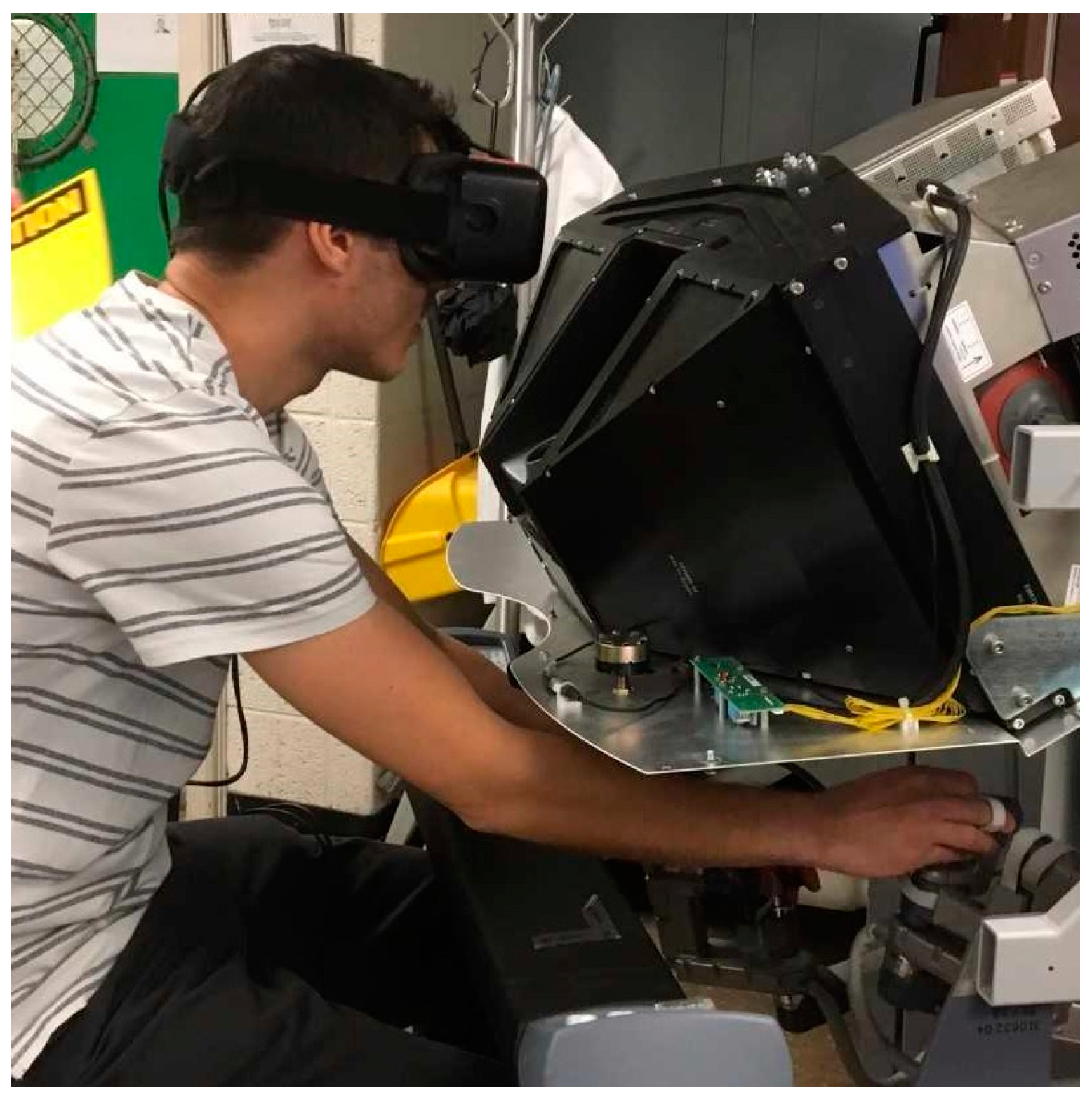
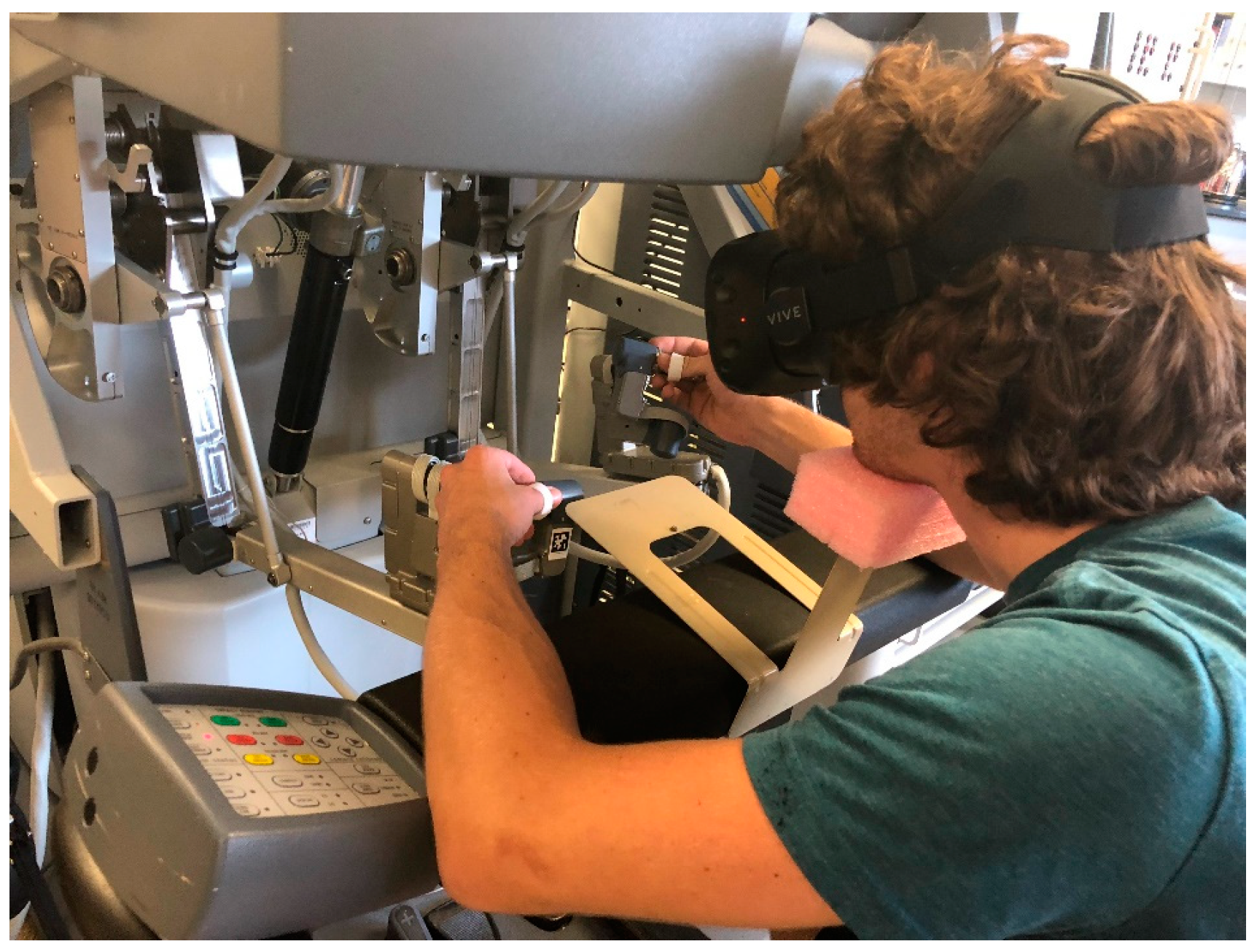
To ensure that the movement method of the camera arm was the only item we tested, we normalized the study by using the same HMD for two conditions. In test 1, the HMD was free to be moved and its orientation controlled the ECM camera. In test 2, the HMD was fixed and the camera arm was moved with a standard clutch-based approach. In this setup, the participant wears the HMD and comfortably places his/her chin on a chin rest which is fixed to the arm rest of the surgeon console (
Figure 10). Fixing all the parameters except the ECM movement control methods ensures that the results are not confounded by other parameters, such as screen resolution and comfort of the hardware.
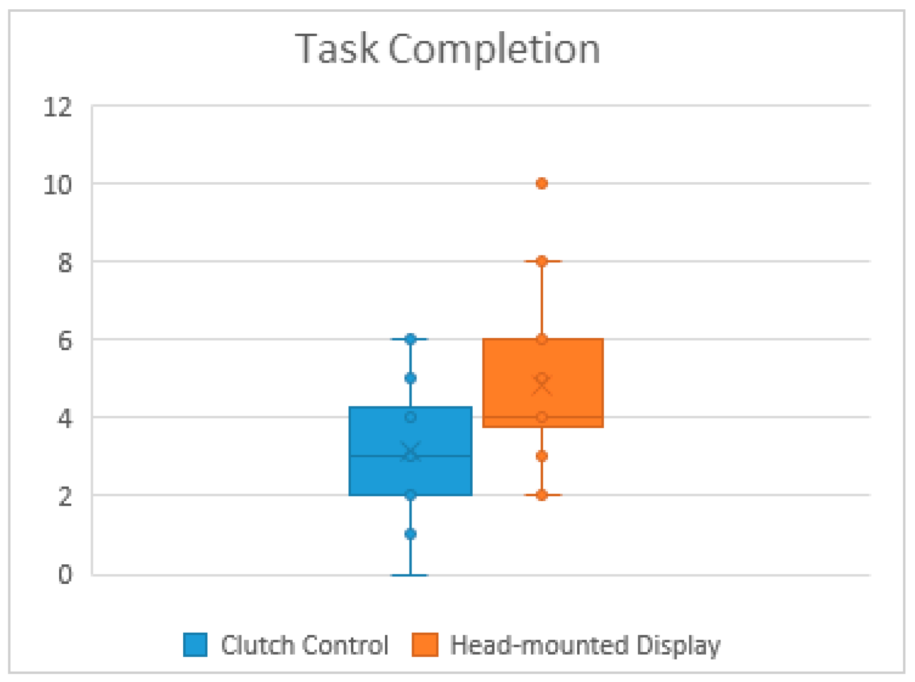
We invited the participants to perform certain tasks using both the HMD control method and the traditional clutch control method for a counterbalanced within subject design. We gathered some performance measures (joint angles, speed, and camera view) and survey results (NASA-Task Load Index (TLX)) for this initial study.
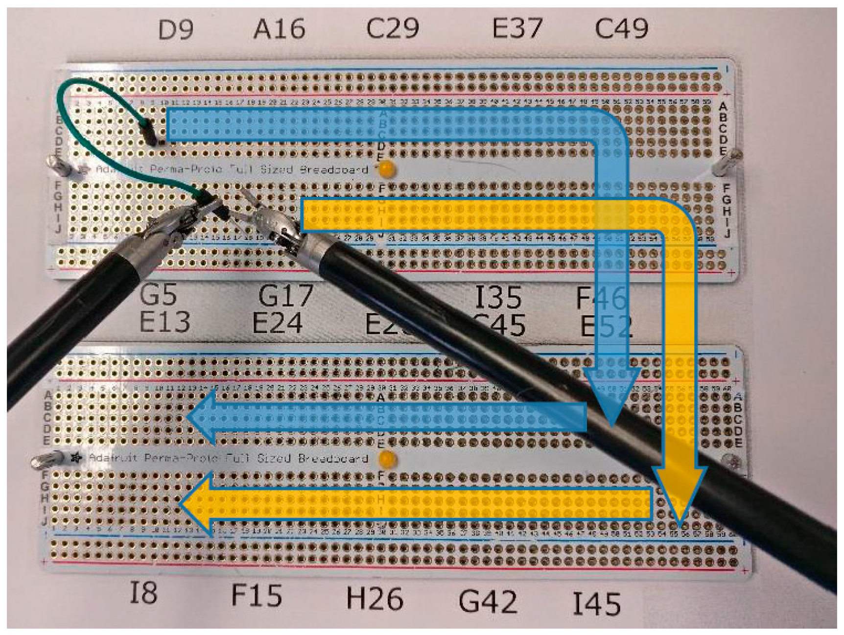
For novice users, learning to suture is very complex and takes a lot of training time. To make our testing task simpler, we have developed a system that incorporates movements similar to suture management and needle insertion, but can be done with less training. It involves simply grasping and inserting a needle attached to a wire into a marked point on a flat surface, as seen in
Figure 11. The tasks start by asking the participant to move each end of a wire from one spot to another on an electronic breadboard following the blue and yellow arrows shown in
Figure 11. The positions in which the wire is placed and where it should go are labeled above and below the breadboard; the rows are labeled from A–J and the columns from 1 to 60. We asked the participants to move both ends of the wire horizontally to the next spots on the upper breadboard (left to right) before moving the wire vertically to the lower breadboard and start moving horizontally again (right to left). The task involved a transfer of the wire tip from one hand to the other at each step. It also involved substantial camera movement including zooming to see the coordinates mapped numbers and letters. This task is like suturing in performance but it is simpler such that it can be performed by a novice user. Moreover, we placed a paper that has an exact image of the breadboards, with the same shape and dimensions, under the actual breadboards so that we could check the punched hole pattern for accuracy. This enabled us to analyze the user progress and detect errors during the test.
The test consisted of eight tasks: one 5-min practice task and three 3-min actual tasks for each of the two camera control methods. The practice task had 20 instructions/steps while each trial had 12. To assure a fair comparison between the two methods, we created 1 pattern for the practice task and 3 different patterns for the actual tasks. In that case, the participant performed the same 3 patterns for each method, but with a counter-balanced and randomized design.
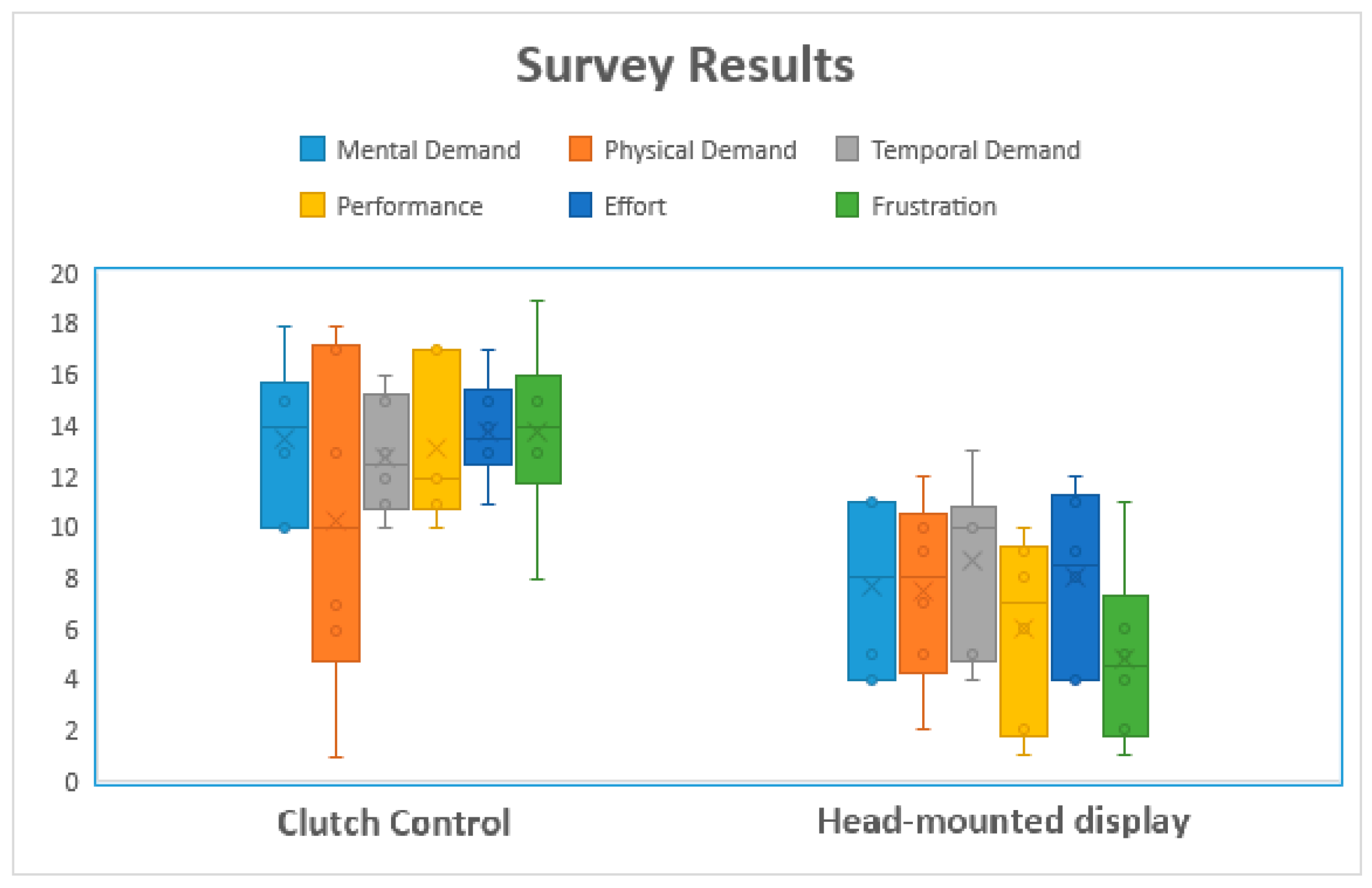
Once all the tasks were completed, we asked the participants to fill out a NASA Task Load Index (TLX) form to assess the workload of each camera control method. NASA-TLX assesses the workload of each method based on 6 criteria: mental demand, physical demand, temporal demand, performance, effort, and frustration. In addition to NASA-TLX forms, we asked the participants to answer two questions:
- (1)
“Did you become dizzy or have any unpleasant physical reaction?”
- (2)
“Did you feel your performance was affected by any of the following: movement lag, image quality, none, or other?”
The purpose of the two questions was to determine if the headset may have a negative effect on the user when used for a certain period. This preliminary testing took approximately 45–60 min per subject.
For consistency and ease of running our usability test, we also created a graphical user interface that consisted of three main functions: a recording function to log the pose of the camera arm, a function to select which camera control method the test will use, and a timer to keep track of the task time limit.
