1. Introduction
People with motor infirmity or lack of full control of their upper limbs have problems working with physical user interfaces, such as gamepads or joysticks. They need an intuitive and hands-free human machine interface (HMI) to work with computer systems. This problem is escalated for pupils with cerebral palsy (CP), encephalitis or upper limb disabilities in using the controller of video games such as the Xbox [
1]. To play games, they typically need a hands-free interface that does not require direct physical contact and motor motions. A vision-based human machine interface (VHMI) applies computer vision techniques to detect head gestures and render game commands. It could be used as an alternative to a physical gamepad and provides hands-free HMI to interact with video games without massive upper limb motions. This helps people with motor disability to interact with the game using head gestures [
1,
2,
3].
Video streams are high-dimensional and often redundant data carrying rich information. Feature tracking (FT), also known as optical flow, is a computer vision-based method to identify motion in a sequence of frames. It detects the flow of hundreds of feature points in consecutive images, which, if properly adjusted, can be used to estimate motion information. For instance, it could be used to recognize head gestures in consecutive frames supplied by a camera [
1]. Optical flow naturally involves huge data processing and this is a challenge for real-time applications. Feature selection limits the region of interest and makes the tracking algorithm efficient. Furthermore, a change in the appearance of a moving object, varying illumination and occlusion cut off the continuity of the optical flow and makes it malfunction. The Kalman filter is an optimal estimator and can be used to estimate the trajectory of a moving target in the presence of occlusion.
The application of vision-based HMI using either head gesture or hand movement has long been a favorite of many research works [
4,
5,
6]. Ernst et al. [
7] presented a real-time adaptive method of motion tracking for imaging and spectroscopy, and Huang et al. [
8] applied temporal filters to develop a robust face tracking system. Optical flow was used in [
9] to build 3D facial expression recognition. Ali et al. [
10] proposed a visual tracking system using the Kalman filter. Maleki and Ebrahim-zadeh [
11] developed a visual mouse system using hand motion recognition in consecutive images and finally, Khandar et al. [
12] proposed a mouse control system using vision-based head movement tracking.
A visual HMI was developed by Jia et al. [
13] to manipulate an electrical wheelchair using head gestures. They built a combination of nose template matching, Camshift object tracking and face detection. Lu et al. [
14] represented a vision-based HMI to distinguish nod and shake. The position and orientation of the head were initially identified using the multi-view model (MVM), and later, the hidden Markov model (HMM) was adopted to recognize head gestures using statistical inference. In the following, Lu et al. [
15] applied the Bayesian network framework to MVM to identify head gestures. Later on, color information was inserted into the Bayesian network in order to enhance robustness and performance [
16].
Head gesture-based HMI usually experiences a deficiency of robustness in performance. This is mainly due to interruption produced by the habitual behavior of eyes’ target-tracking. This makes the head return to its original pose immediately after any gesture. This requires fast and precise recognition, in which any tiny head movements are spotted before interruption [
1]. The method proposed by Jia et al. [
13] could not spot small head movements, since it works based on nose position in the center of the face, and this needs to be large enough. Furthermore, the face detection approach is very dependent on head pose. If the head is facing directly towards the camera, face detection works properly, and it fails when movements make the face unrecognizable. Meanwhile, real-time control of a video game urges rapid and robust reactions, and this is a challenge in feature tracking, which involves a huge number of features under various occlusion and light conditions. Han et al. [
17] proposed a real-time method to evaluate the weights of the features using the Kalman filter. It comprises inter-frame predication and single-frame measurement of the discriminative power of features. They showed that this method can stabilize the tracking performance when objects go across complex backgrounds [
18,
19].
To deal with problems raised due to occlusion, Han et al. [
20] applied feature tracking in three steps: initially detecting the moving object, then tracing feature points within the object mask and finally estimating the trajectory of the object. Hua et al. [
21] proposed a way to combine occlusion and motion estimation with a tracking-by-detection approach. The motion changes of the object between consecutive frames was estimated from the geometric relation between object trajectories. Real-time vision-based inertial navigation was presented by Mourikis and Roumeliotis [
22]. They applied the extended Kalman filter (EKF) and deployed a measurement model to represent the geometric constraints. Shiuh-Ku et al. [
23] designed an adaptive Kalman filter (AKF) to track the moving object. They used the rate of occlusion to adjust the error covariance of the Kalman filter, adaptively. The adaptive Kalman filter improves the tracking performance in situations such as changing lighting and partial and/or long-lasting occlusion in real-time applications [
19].
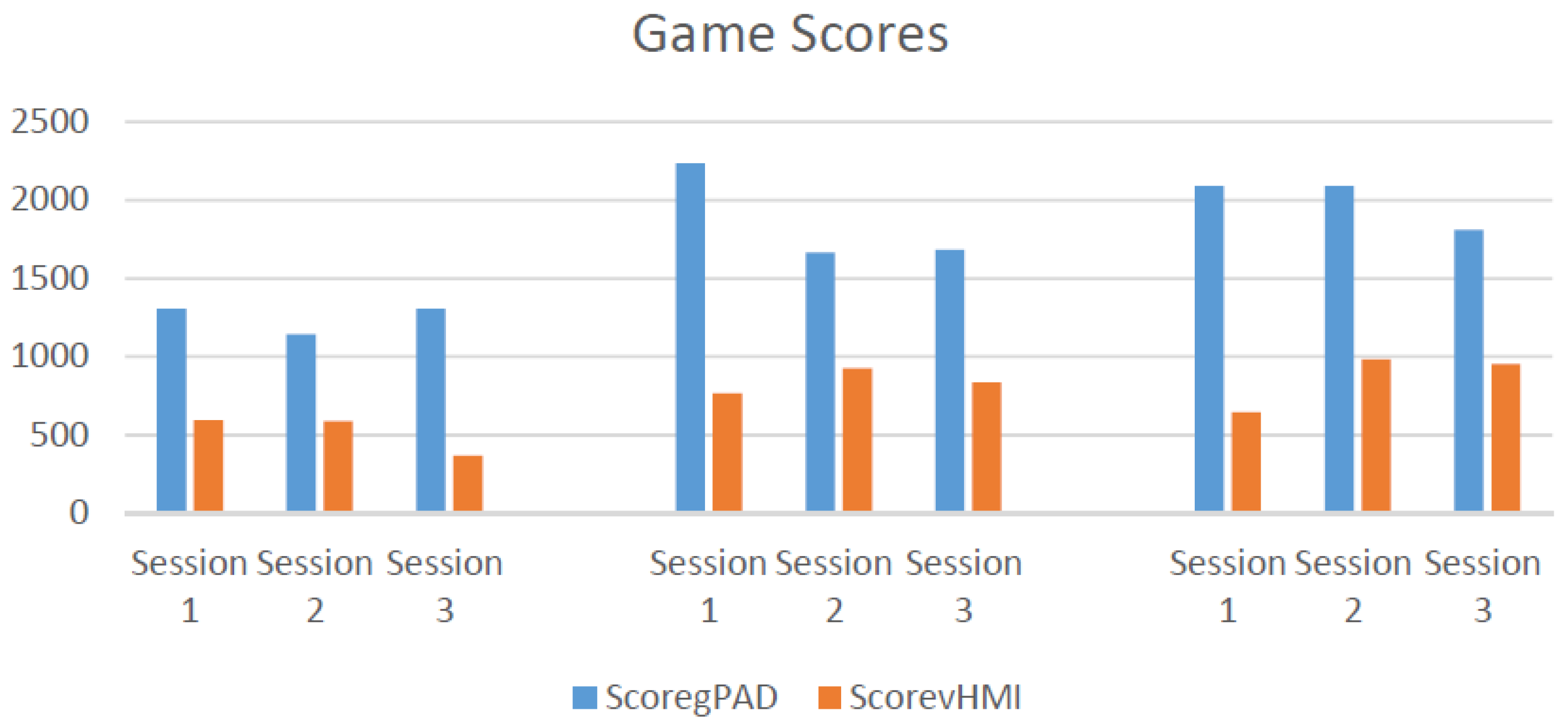
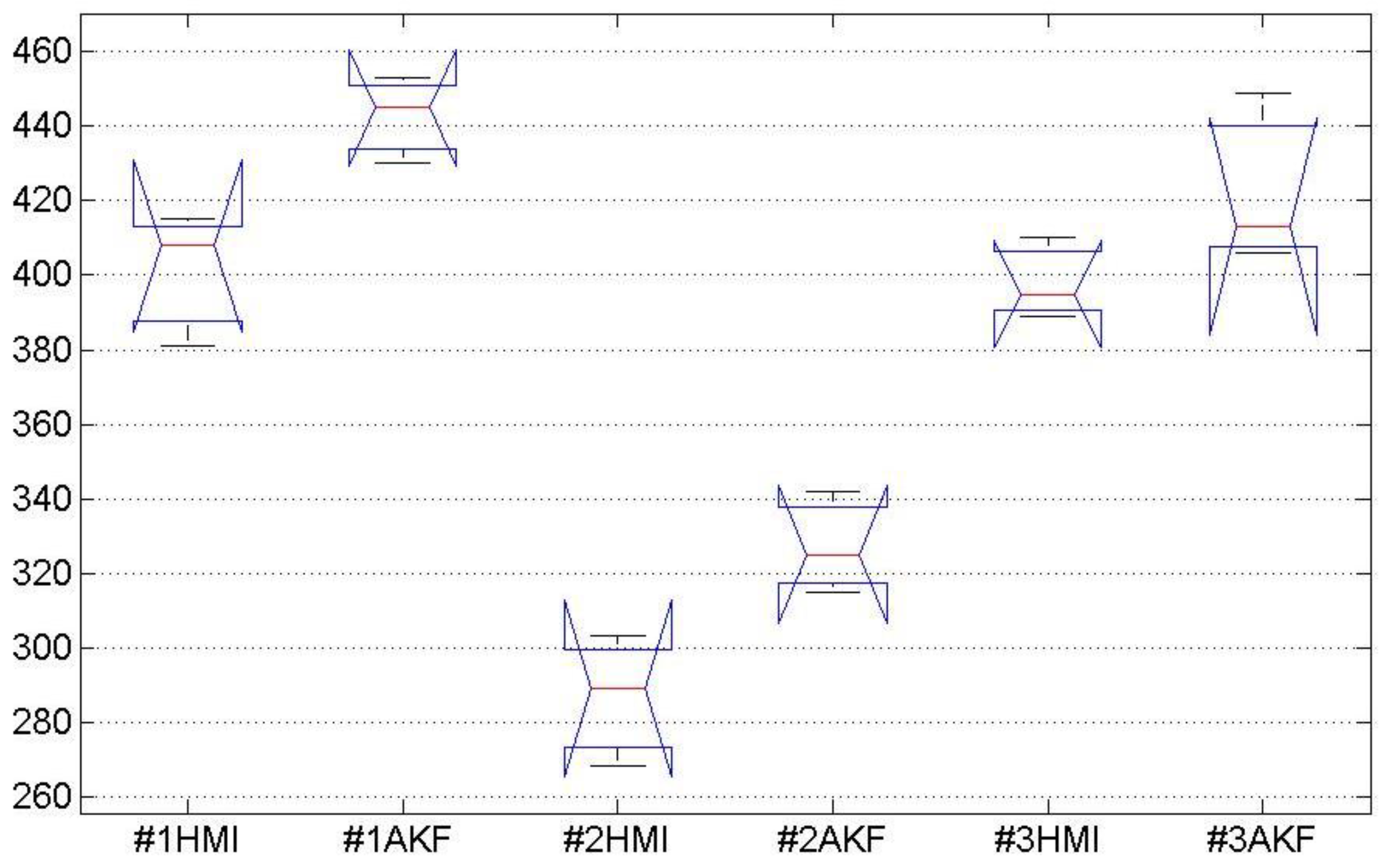
This paper proposes the adaptive Kalman filter (AKF) to improve the performance of a vision-based head gesture interface to a video game. The vision-based interface detects the region of the head by face detection and applies optical flow to recognize head gestures. Head gestures are classified into five pre-trained classes corresponding to five commands that manipulate a car in a route with randomly appearing obstacles. Face detection often fails due to either the change in head posture, illumination or occlusion. Failure in face detection leads to missing optical flow and eventually malfunction in manipulating the car. In the video game, any safe movement is rewarded by a positive score, and a malfunction in manipulating the car and hitting obstacles are penalized by a negative score. Hence, the achieved scores of the game can be considered as a measure of the performance of the vision-based interface.
Failures in face detection, no matter the reason, are considered as a kind of occlusion and represented by the occlusion rate. The Kalman filter is to estimate head motion by adjusting in-between measurement and prediction. The measurement is obtained from optical flow, and the prediction is from estimated motion in the recent consecutive frames. The occlusion rate is applied as an adaptation parameter of the Kalman filter to adjust in-between measurement and prediction. The experiment is designed to evaluate the improvement made by AKF applied to the vision-based interface while playing a video game. This paper is an extension of our previous work [
1], where we developed head gesture-based HMI as an alternative to gamepads for the Xbox game.
The paper is organized into five sections. Following the Introduction,
Section 2 presents models and methods employed in this study, including the pyramidal implementation of feature tracking, feature selection and the adaptive Kalman filter algorithm. The structure and implementation of the proposed vision-based HMI is described in
Section 3. Experiments are conducted in
Section 4 to demonstrate the performance of the proposed vision-based HMI. Finally, the paper concludes with a brief discussion and future work in
Section 5.
2. Models and Methods
This section describes models and methods that were employed in this study to build the vision-based human machine interface.
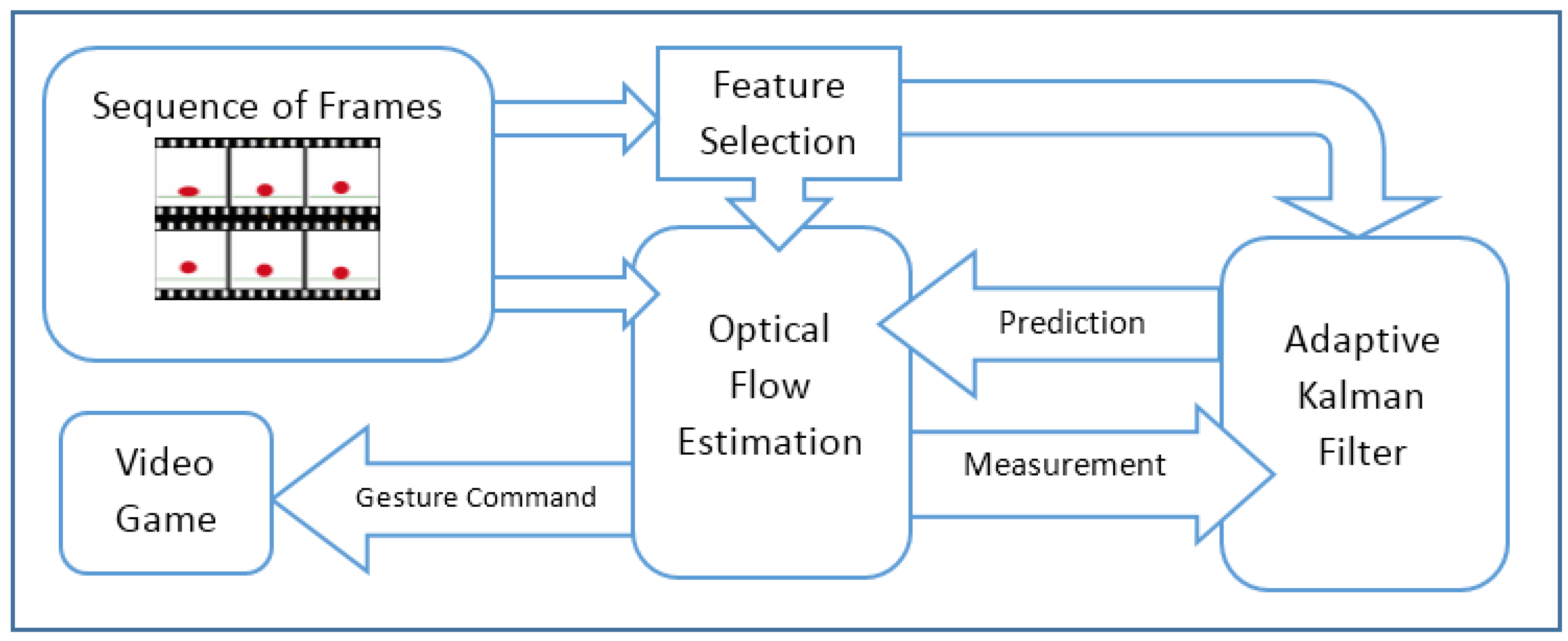
Figure 1 depicts the schematic diagram of the proposed HMI, which is made up of three main components: feature selection, optical flow estimation and adaptive Kalman filter. Feature selection is to identify the major neighborhood of the moving pixels and solve the optical flow equations for just those areas. Face detection is applied to identify the neighborhood of pixels around the head. The optical flow method introduced by Lucas and Kanade [
24] is a widely-used approach to identify motion in consecutive frames. It assumes the flow is constant in neighbor pixels. The adaptive Kalman filter estimates the motion information of the selected features under a weakening condition, such as occlusion.
2.1. Optical Flow Estimation
In computer vision, optical flow is the pattern of motions caused by relative movement between the camera and objects. The Lucas-Kanade algorithm [
24] is a differential method to estimate optical flow in consecutive frames. It assumes that the flow is constant in the local neighborhood of pixels, known as features. The features are regions of interest for which the optical flow equations are solved. A head gesture in front of a static camera produces a set of local features with almost constant flow. Let us consider
I(
u,
t) representing a feature located at
in time frame
t. The variables of
x,
y and
t are discrete and bounded suitably. Generally, most of the consecutive frames are either similar or strongly related to each other, since they are taken at near time instants. In the case of smooth motion in the scene, it keeps the similarity or relation with slight relocation. Smooth motion means relocation in the scene that can be captured in consecutive time frames and expressed by (1). Formally, this means that
I(
u,
t) is not arbitrary, but satisfies the following property:
To estimate optical flow in two successive grayscale frames, represented by
I(
u) and
J(
u), the objective is to find a point
v = u + d such that
I(
u) and
J(
v) are approximately similar. The displacement vector
is used to work out the velocity of the flow at the point of
u. The similarity is defined in a sub-window centered at point
u, with a size of (2
wx + 1) × (2
wy + 1), and the displacement vector of
d is calculated in a way that minimizes the residual function (2).
The sub-window is called the integration window and the displacement vector of
d is calculated iteratively. The window size and initial guess of the displacement vector are both crucial parameters for the time complexity of optical flow estimation. Furthermore, the size of the integration window makes a trade-off between the accuracy and sensitivity of estimation. A small size of integration window enables the detection of very tiny motions around
u; meanwhile, this may miss the detection of large motions. A large-sized integration window leads to the detection of displacements with low resolution. Practically, the integration window is chosen between 3 × 3 and 7 × 7. In general, displacements should be less than the window size, i.e.,
dx ≤
wx and
dy ≤
wy, but the pyramidal implementation of Lucas-Kanade algorithm [
24] overcomes this limitation.
2.2. Pyramidal Lucas-Kanade Algorithm
An implementation of the Lucas-Kanade (LK) algorithm was presented by Bouguet [
25]. Pyramidal implementation reconstructs an image window in higher levels with a smaller size. This allows examining windows at different levels and detecting motions larger than the size of the integration window. For an image with a size of
nx ×
ny at the base level
I0 =
I, the pyramidal implementation reconstructs images at higher levels with smaller sizes, recursively. For instance,
I1 is formed as a quarter size of
I0, and
I2 is formed as a quarter size of
I1, and so on. The pyramidal level
IL is formed from
IL−1 based on (3). As shown in
Figure 2, consecutive images were formed into pyramids with 2, 3 or 4 levels, and the LK algorithm was applied to the levels, respectively. The number of levels in the pyramid is chosen according to the maximum expected optical flow in the image [
25].
By constructing pyramidal levels, the KL algorithm is initially applied at highest level
Lm. It estimates optical flow by calculating the displacement vector that minimizes the residual function at this level. Then, it is used as the initial guess to speed up optical flow estimation in the level
Lm−1. The optical flow is propagated to level
Lm−2, and so on, up to the level
0, the original image [
25].
In level
L, given the initial guess
and optimum displacement
result in the initial guess in
L − 1 by
, the algorithm ends as it reaches level
0. To initialize the algorithm, we set
and the final optical flow solution is obtained by
. The algorithm is expressed by the extended form of (4).
Equation (4) demonstrates the advantage of the pyramidal implementation. Even though, the small window size at higher levels ends up with a large displacement vector at lower levels. This supports a balance between the accuracy and sensitivity of the algorithm. Given
dmax as the maximum displacement vector at each level, the pyramidal implementation can detect motions with displacement up to
dmax final = (2
Lm+1 − 1)
dmax. For example, a pyramid with
Lm = 3 can detect motions fifteen-times larger than of what ordinary LK can detect [
24,
25].
Now, let us review the calculation of the LK algorithm at each level. Consider two successive frames in level
L, as
A and
B in (5), and the residual function that should be minimized at
p = [x y]T = uL with displacement
v = [vx vy]T is defined in (6).
The optical flow is displacement
v* that makes the first derivative of the residual function (6) equal to zero and is obtained by (7).
where:
and:
Spatial derivatives
Ix and
Iy of the fixed frame are calculated once at the beginning of the iterations. Therefore, the matrix
G remains fixed during the iterations, and this brings a computational advantage. The residual difference between the frames (
bk) needs to be calculated at each iteration. More details of the computations are presented in [
25].
2.3. Feature Selection
In the previous section, optical flow was estimated using tracking features in the consecutive frames. Due to computational limits, it could not be applied to whole image pixels, and we should select points for tracking. This is called feature selection. Based on the KL algorithm, the
G matrix of the selected feature, defined in (8), should be non-singular, and in practice, its minimum eigenvalue should be large enough. Therefore, this could be used as a criterion to select feature points, which are typically good for tracking. The feature points are chosen in a way that they are far enough from each other to avoid locality in the detected optical flow. The detailed procedure of feature selection is presented in [
25].
Face detection often fails due to the change in head pose, illumination and occlusion. Failure in face detection leads to missing optical flow and eventually malfunction in manipulating the car. Failures in face detection, no matter the reason, are considered as a kind of occlusion and represented by the occlusion rate. The occlusion rate is in the range of [0, 1] and worked out by the number of frames without a detected face in the recent k frames divided by k. Its value of one means that there is no detected face in the last k frames, and the value of zero means all the recent frames had detected faces. The occlusion rate is applied as an adaptation parameter of the Kalman filter to adjust in-between measurement and prediction.
2.4. Adaptive Extended Kalman Filter
The Kalman filter is an optimal state estimator and has a wide range of applications in technology. It is a recursive algorithm that produces estimates of states that tend to be more precise than those based on a single measurement alone. The algorithm is built on two models, the state model and the measurement model, which are defined in (10) and (11), respectively.
where
X(
t) and
Z(
t) are state and measurement vectors and
W(
t) and
V(
t) are white Gaussian noise with zero mean and the covariance matrix of
Q and
R, respectively, and
δkl denotes the Kronecker delta function. The Kalman filter consists of two steps: prediction and correction. In the prediction step, it deploys the state model and produces the estimate of the current state and its uncertainty.
where
and
are prior and posterior state estimates and
and
are the prior and posterior state covariance error, respectively. In the correction step, once the measurement is observed, the posterior estimates are updated using a weighted average, in which more weight is given to estimates with higher certainty.
The Kalman gain factor, K(t), is in an inverse proportion of the measurement error R, and it adjusts weight in-between the measurement and the predicted estimate. The extended Kalman filter (EKF) has been developed to work on the system, in which both or one of the state and measurement models may be nonlinear. In EKF, the partial derivatives of nonlinear functions, which are the differentiable type, are applied to proceed with the prediction and correction steps. This process essentially linearizes the nonlinear function around the current estimate.
In this work, we used the adaptive Kalman filter that was developed by Shiuh-Ku et al. [
23]. The proposed Kalman filter estimates motion information extracted by feature tracking. It adapts the filter parameters to overcome deteriorating conditions such as occlusion. This means that the Kalman gain factor is adjusted based on occlusion. The state model is a linear motion model, which is formed based on the optical flow of the last two frames. The outcome of the LK algorithm is used as the measurement for the correction step. In the consecutive frames, the time interval is very short, then velocity is assumed uniform and used instead of position in the model [
23]. Therefore, we can model the displacement vector in time intervals as (18).
where
,
d(
t) and
d(
t − 1) are the displacements vectors at frames
t and
t − 1, respectively. Having displacement in the x-axis, y-axis directions (
dx,
dy), the state model and the measurement model are defined as (19) and (20), respectively.
Having the state model and the measurement, we can apply the AKF to track the features effectively in a sequence of frames. The AKF models are designed in such way that the estimate parameters adjust automatically. Occlusion makes the optical flow fail and leads to error measurement for the displacement vector. This means that the occlusion rate is proportional to measurement error and can be applied to adjust estimation parameters.
The Kalman gain factor K as shown in (15) is in inverse proportion to measurement error R. Where there is a lack of occlusion, measurement error of R and prediction error of Q could be assumed infinity and zero, respectively. In the presence of occlusion with a rate of α, the measurement error of R is set to α and the prediction error of Q is set to 1 − α, if it exceeds a predefined threshold. In other words, if the occlusion rate is less than the threshold, then the measurement result will be trusted more than the predicted one. Otherwise, the system will trust the predicted result completely. By this, the Kalman filter is adjusted based on the occlusion rate, adaptively.
At the end of this section, let us review the structure of the proposed vision-based HMI. Initially, face detection was applied to the stream of frames captured by the camera in front of the subject. It simultaneously identifies the region in which the head in and updates the certainty of face detection. Then, feature points were chosen in the region identified by face detection. Feature tracking was used to estimate the optical flow made by the head gesture. The adaptive Kalman filter is applied to estimate the feature points’ motion, particularly in the case of occlusion. In the tracking procedure of the adaptive Kalman filter, a motion model is constructed to build the system state and is applied to the prediction step. The occlusion ratio is applied to adjust the prediction and measurement errors adaptively. The two errors will make the adaptive Kalman filter system trust the prediction or measurement more and more. The occlusion rate is extracted using face detection performance.
3. System Implementation
The proposed vision-based HMI is implemented to work in parallel with a gamepad to manipulate a car in either an Xbox or a home-developed video game. In both games, it detects user’s head gestures and overrides commands from the gamepad using gestural instructions. In the Xbox game, the system runs two independent threads simultaneously: a thread that forwards the arriving commands from the gamepad to the video game and a thread that detects gestural commands and overrides some ordinary commands of the gamepad. It was implemented in Java, but equipped with a C++ core (as a DLL file) to handle video data processing and feature tracking using the OpenCV 2.x library [
26]. This core was adopted by means of the Java native interface (JNI) in the main program.
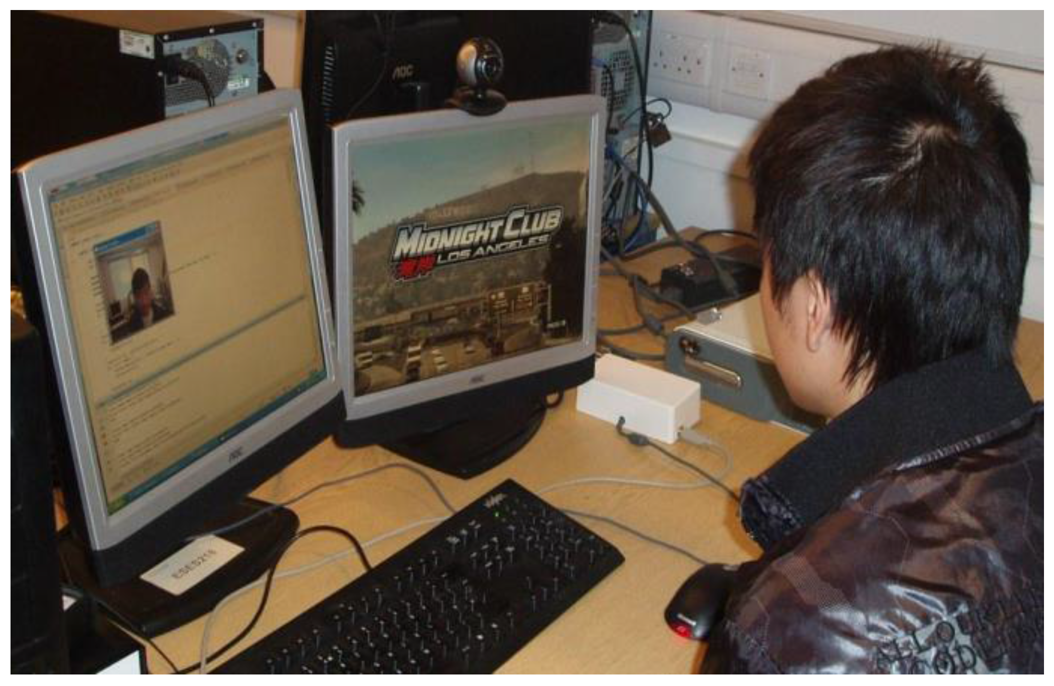
Figure 3 depicts the hardware setup, and
Figure 4 illustrates a subject playing the Xbox game through the vision-based HMI. For the Xbox, the user could run the racing car forward, left and right using head gesture towards the up, left and right directions, respectively. The stop command was associated with the head’s normal situation at the beginning. The Xbox Java SDK was deployed to read the controller connected through the USB into a dual-core 3.2-GHz PC, and then, the commands were forwarded to the Xbox via a hardware interface connected to the USB port using the Java Serial Communication SDK [
1].
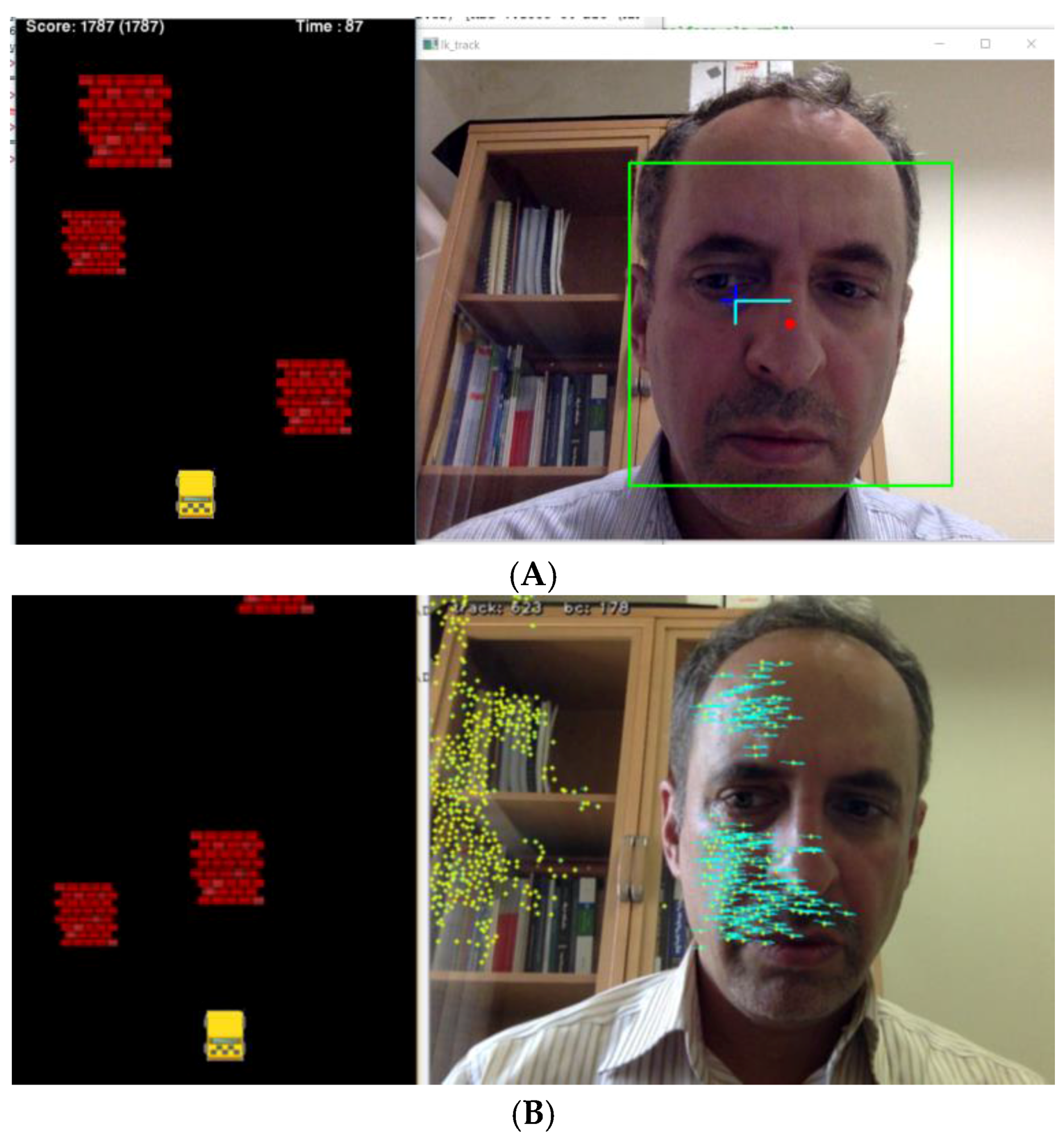
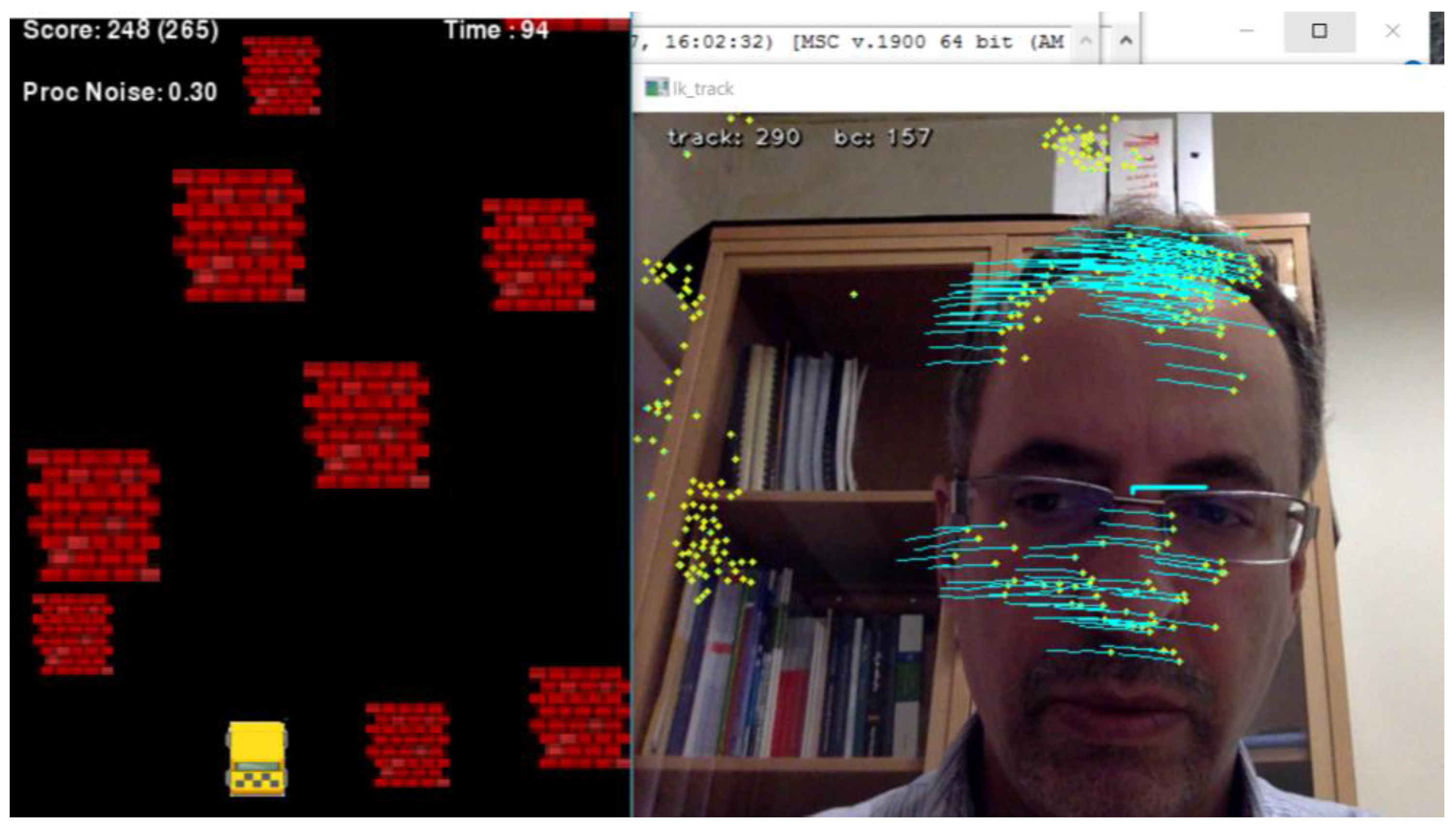
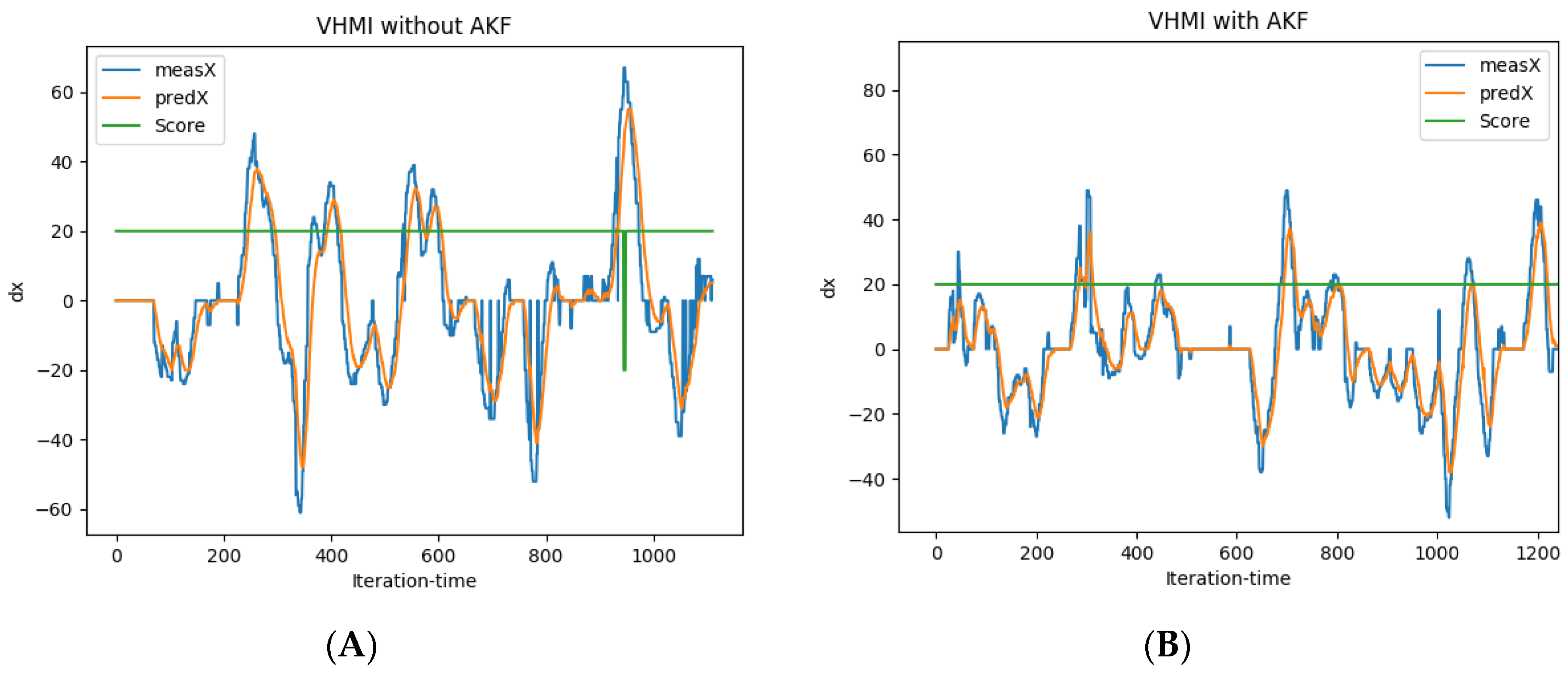
The recent vision-based HMI and video game were both developed in Python 3.6 using the OpenCV 3.2 and PyGame libraries, respectively, and run in two threads in parallel using the Python Threading library. The vision-based HMI grabs the video stream captured by the camera, which is fixed on top of a screen illustrating the video game. It has two modules, face and optical flow detectors, and works in two modes: face detection mode and optical flow detection mode. In the former, head gestures are recognized through the shift of detected faces in consecutive frames, as shown in
Figure 5A. While in the later, the average of optical flow made by features in the face ROI is used to address head gestures (
Figure 5B). The output of the vision-based HMI is passed through two filters: a low-pass filter and the adaptive Kalman filter (AKF); both were implemented in Python using the OpenCV, SciPy and NumPy libraries. The video game is made up of a player yellow box (car) and randomly appearing red boxes (obstacles). The video game and vision-based HMI are run in parallel in multi-thread mode, and subjects should avoid hitting obstacles using head gesture to manipulate the car (
Figure 5).
Since there is no direct access to the Xbox scoring system, we adopted a home-developed video game to directly record game scores and evaluate the HMI performance. The game has five ordinary commands: forward, backward, right, left and stop. The commands are produced by vision-based HMI using head gestures. The higher score shows quicker and safer forward driving. The scoring policy is designed for safe driving as much as possible by penalizing wrong movements. Forward movements reward with a positive score, and a wrong step, in which car hits an obstacle or border, is penalized by ten negative scores. The subjects were encouraged to advance to the highest score as much as possible. Hence, the game was played by the subjects until they were not able to get more scores continuously.
In the operation mode, the vision-based HMI supersedes the gamepad and sends commands directly to the video game. It enables the user to control the game without the gamepad. In the video game, the X and Y axis of the gamepad are assigned to move the car towards the left and right, and the Z axis is for either forward or backward movements.
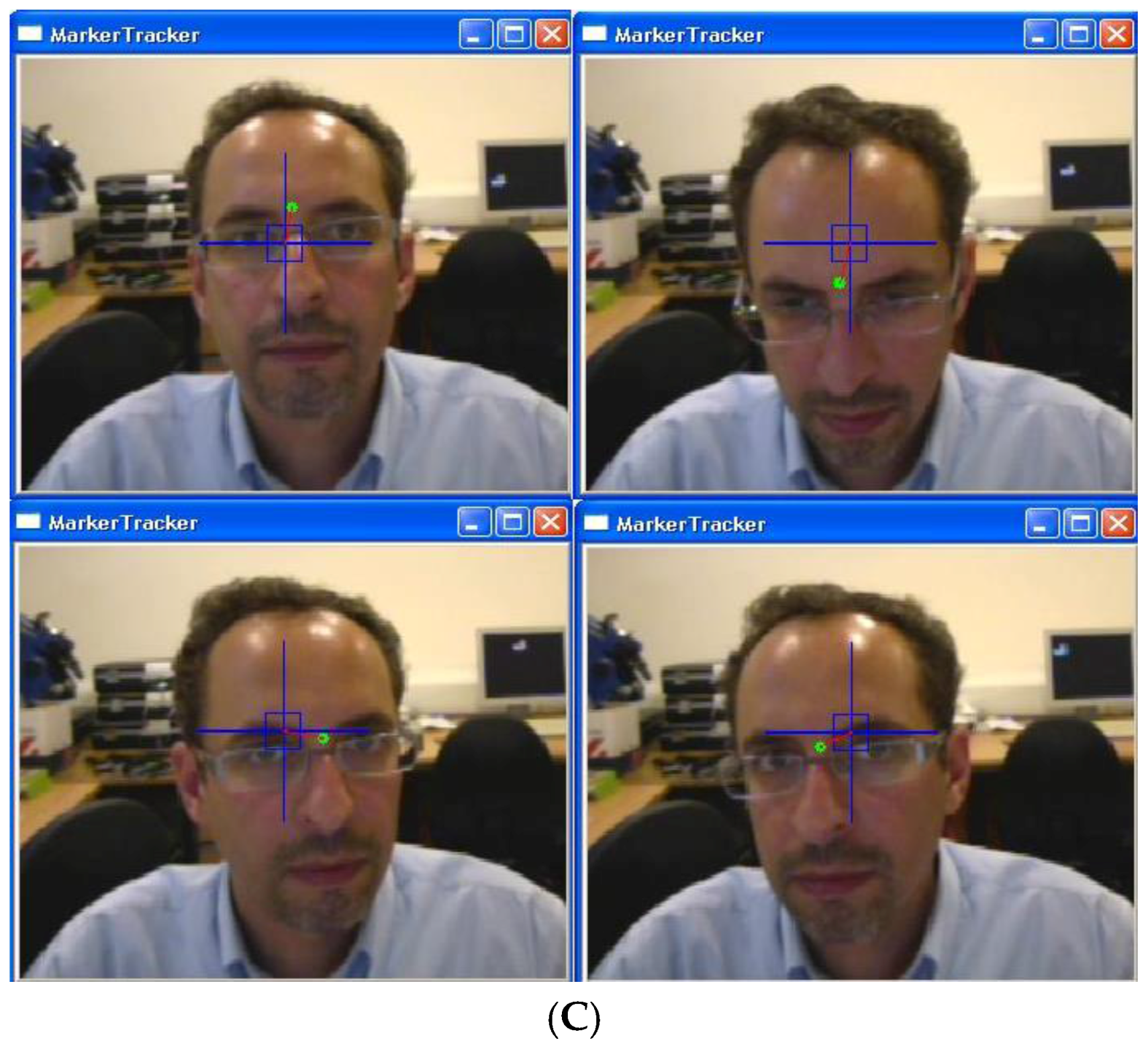
Figure 5 illustrates frames captured by the camera to control the game. Initially, the HMI was calibrated by coordinating motions of the head. Using face detection, a sub-window is localized by the blue frame, and the vision-based HMI becomes activated. Green points depict selected features being tracked on the screen [
1]. The blue rectangle shows margins to address various commands. If the green point is inside the rectangle, it means the stop command. Head gestures traced by the green point address X and Y axis values, while distance from the beginning point (red line) addresses the Z axis value (
Figure 5). Besides manual selection, face detection is employed to select features in the head area. In the proposed HMI, head gestures are recognized using the feature tracking method boosted by an adaptive Kalman filter. The adaptive Kalman filter estimates the motion of feature points that may get lost due to occlusion. This prevents unwanted interruptions during game playing.
