1. Introduction
Legged robots are widely used for a variety of applications, especially in the area of search and rescue operations for their ability to handle uneven terrain [
1]. Legged robots are designed and programmed to respond to various needs based on the task, and offer better stability, manoeuvrability, and energy efficiency. However, any changes in the gait configuration based on the task leads to numerous opportunities as well as research challenges. Legged animals, depending on the task or behaviour, can coordinate a wide range of components and systems to adapt effectively under various conditions such as running, walking, chasing, courtship, and attack [
2,
3].
Various design strategies to generate different gait patterns in legged robots are found in robotic literature. For legged robots, there are many different approaches to generate gait pattern, including: genetic-fuzzy system [
4], reinforcement learning [
5], evolutionary approach [
6], graph search approach [
7], mechanical energy constraints [
8], or neural networks [
9,
10]. Using one degree of freedom based on a reconfiguration planar mechanism, simple control schemes can be proposed as an alternative method [
11]. In [
12,
13], the authors present the Klann based reconfigurable design and implementation where a robot changes its structural morphology by changing its components and sub-assembly parameters to adapt to multi-terrain and multi-tasking by producing a wide set of novel gait patterns.
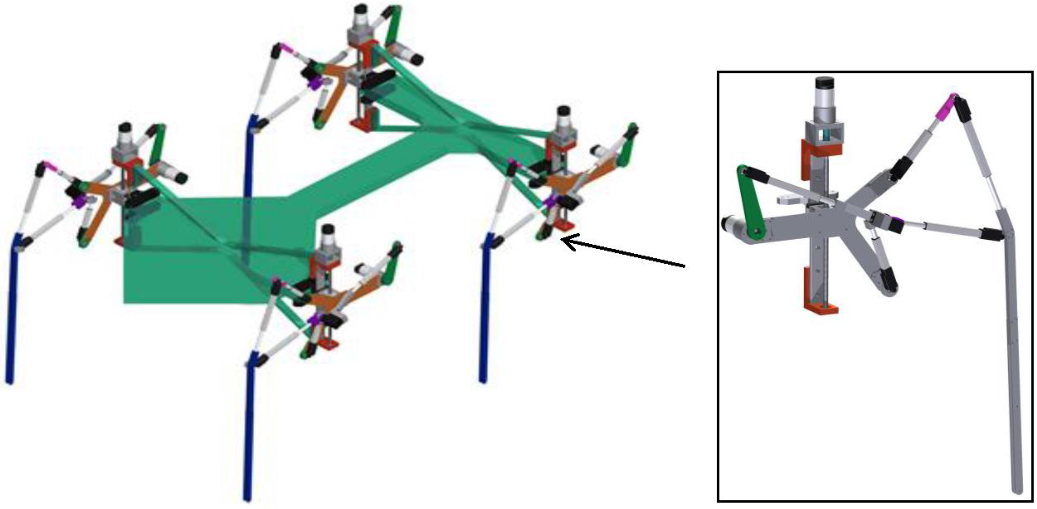
The fundamental challenge in reconfigurable legged robots and associated gait generation is to reach stability in both motion and rest with the minimum number of legs, with a complete range of walking patterns. For quadruped robots with one degree of freedom and reconfigurable legs, input trajectories to synchronize different gait cycles has been discussed in detail in this paper. To clearly explain our approach, we focused on a four legged robot with reconfigurable Klann legs (
Figure 1). By reconfiguring the Klann based legs, six theoretically useful walking patterns resulting from different gait cycles have been achieved. In this paper it is shown that by using the proposed technique, useful feasible patterns can be successfully obtained. By applying the following method, the capabilities of standard non-reconfigurable quadruped Klann legs are significantly extended.
The rest of this paper is organized as follow:
Section 2 presents the specifications of the reconfigurable Klann platform under testing.
Section 3 deals with the design of Trajectory Generation.
Section 4 explains the synchronization method used to coordinate multiple legs to achieve the six distinct [
13] stable walking patterns.
Section 5 presents the static stability analysis of the realized gait.
Section 6 deals with the static and in motion characterization of transformation.
Section 7 deals with the static stability analysis of the transformation.
Section 8 gives a conclusion of this study along with a discussion regarding future work.
2. Specification of the Reconfigurable Klann Platform
In this section, specifications of a developed reconfigurable Klann legged robot is discussed. This designed reconfigurable Klann based walking platform is used herein as a case study for the generation of input joint trajectories to synchronize multiple reconfigurable one-degree-of-freedom legs for realizing stable walking gaits. In our previous work, we have presented a novel approach that produces a wide range of usable gait curves for Klann based reconfigurable legged robots during locomotion [
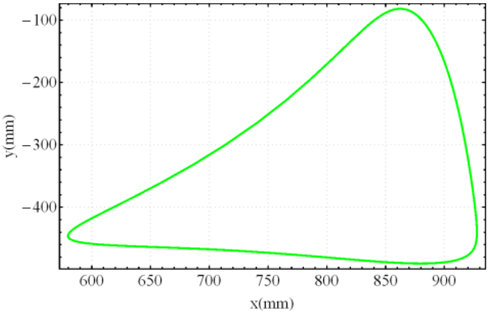
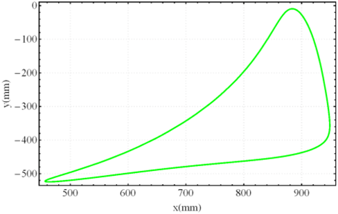
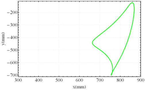
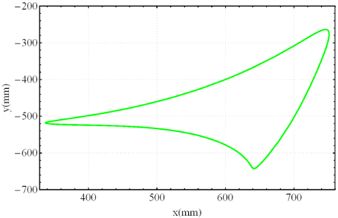
13]. By changing its link length parameter, such a robot can vary its hardware morphology. During the reconfiguration process the recommended mechanism switches from a pin jointed Gürbler kinematic chain to a seven degree-of-freedom mechanism with slider joints. The proposed design, while maintaining efficiency, extends the capability of the original design to not only produce distinctive useful gait patterns but realize behaviour beyond locomotion. The identified novel gait patterns are shown in
Table 1.
For most legged platforms, one of the important factors is to determine the required number of legs to obtain stability during motion and rest. Previous works related to legged platforms utilize more than four legs to overcome stability issues [
14]. The challenge faced with the legged platform is that increase in the number of legs to overcome stability issues will give rise to other problems such as cost, size, complex control system, and associated maintenance issues. For a platform with reconfigurable legs, this problem is even more obvious because of changing leg dimensions associated with the task. Thus, increasing the number of legs will directly contribute to the complexity of the entire system. As discussed, it is important to develop a reconfigurable walking platform with a minimum number of legs. However, reconfigurable designs with less than four legs should be avoided in order to maintain simplicity and at the same time to avoid the related considerations of Zero Moment Point (ZMP) approaches for achieving static and/or dynamic stability [
15,
16,
17,
18]. In addition, toe slipping due to difference in leg speed during realization of a walking pattern need to be taken into consideration [
18]. As a consequence, a four-legged reconfigurable Klann platform is considered for the analysis discussed in this work.
Figure 1 shows the CAD design of the four-legged Reconfigurable Klann platform. Using this robot, with reconfigurable capabilities, the results of six gait patterns are tabulated in
Table 1. Each leg is controlled independently by a rotary actuator with its control system. In the following section, the formulation for the trajectory generation of input joints is presented.
3. Trajectory Generator Planning
In this paper, we use cubic polynomial interpolation to help the leg generate a smooth trajectory from starting point to ending point. The input angle and speed are represented as third and second degree. Since the position and velocity of the crank are controlled through a continuous function with a degree higher than one, the load force applied to the main actuator can be decreased to a minimum. Because of these advantages, we have used this method for our trajectory generation. This approach has already been successfully used in the community [
19,
20,
21].
We define the input angle (crank) as
and the speed of the crank as
in term of time
. The cubic polynomial interpolation function can be defined as follow:
where
represents coefficients and these are derived from two consecutive points in a set of four (
,
,
,
) of a given trajectory. The first point can be considered as the initial state (
) and the next point as the final state (
) where the execution time is from 0 to
(constant) (s). From the initial state,
and
can be derived:
With the final state (which is already planned), we have:
From Equations (3)–(6) we have:
Then, from Equations (3), (4) and (7) we have all the coefficients .
Using the Trajectory Generation method as earlier explained, our strategy for synchronization is designed. As the third degree polynomial interpolation can be calculated uniquely, based upon the initial condition , the final conditions , and the transformation time , the synchronization strategy is therefore designed by defining these states.
4. Walking Phase Synchronization
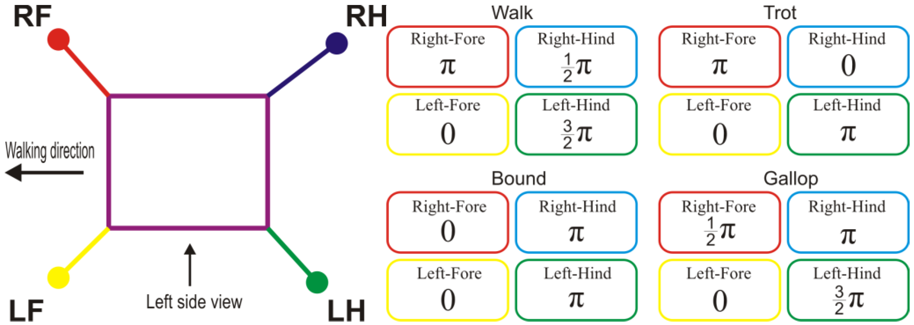
Apart from planning a suitable trajectory corresponding to different terrains, reconfigurable quadrupled Klann platforms must have a leg synchronization strategy to achieve a stable walking gait. Several locomotion patterns including “walk”, “trot”, “bound”, and “gallop” as in
Figure 2 are available from the literature [
22] for the case of a general multi-legged robot. Specifically, in this part, we focus on the synchronization strategy for the “walk” pattern. The other three patterns, where only two legs contact the ground surface at a specific time, are left for future work.
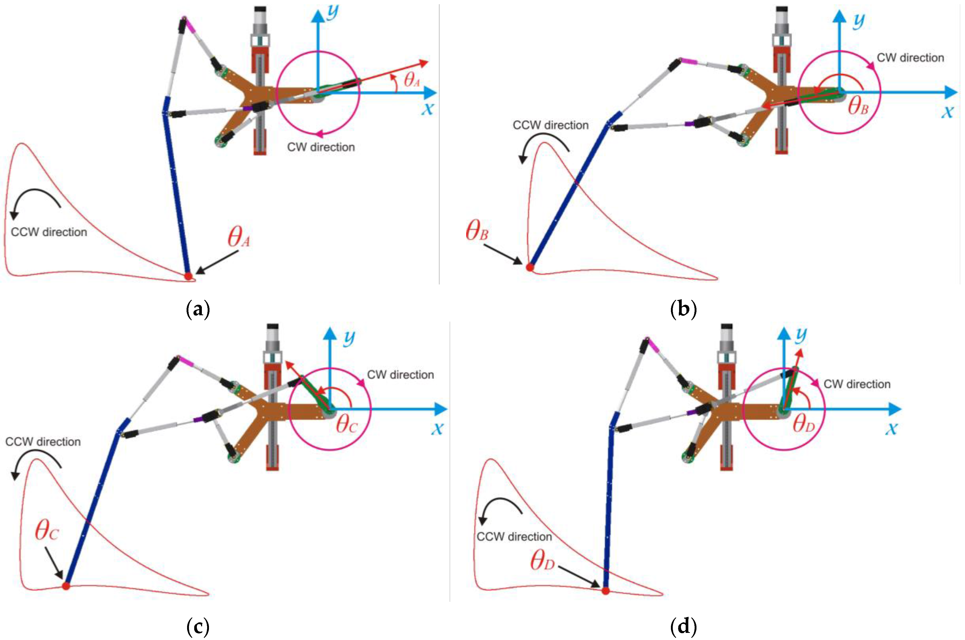
Figure 2 (left) shows the overall definition for all four legs of the robot as well as viewing directions that will be used to evaluate the input angles of the four legs in
Table 1.
It can be seen from
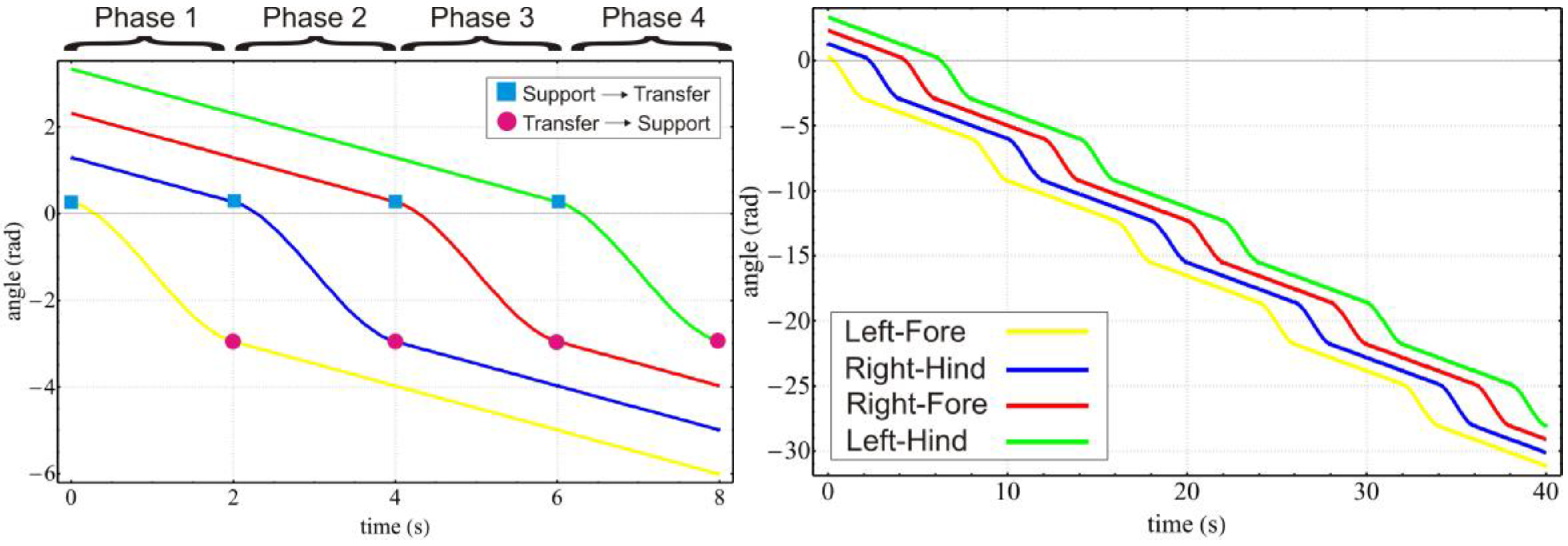
Figure 2 that in a walk pattern, there is a shift of 90 degrees among the four legs’ phases. “Transfer” and “support” are used as terms for describing states of the leg that swings over the ground and touches the ground respectively. At any moment, only one leg is in transfer phase while the other three legs are in support phase to carry the mass of robot. The switching sequence of the transfer leg is “Left-Fore” → “Right-Hind” → “Right-Fore” → “Left-Hind”, and so on. The trajectory generator using cubic polynomial interpolation introduced in
Section 3 is used to produce a smooth transition from current state to next one. Since Klann is a one degree-of-freedom linkage, the end point of the leg depends only on the angle of the driving link, the input angle, defined as
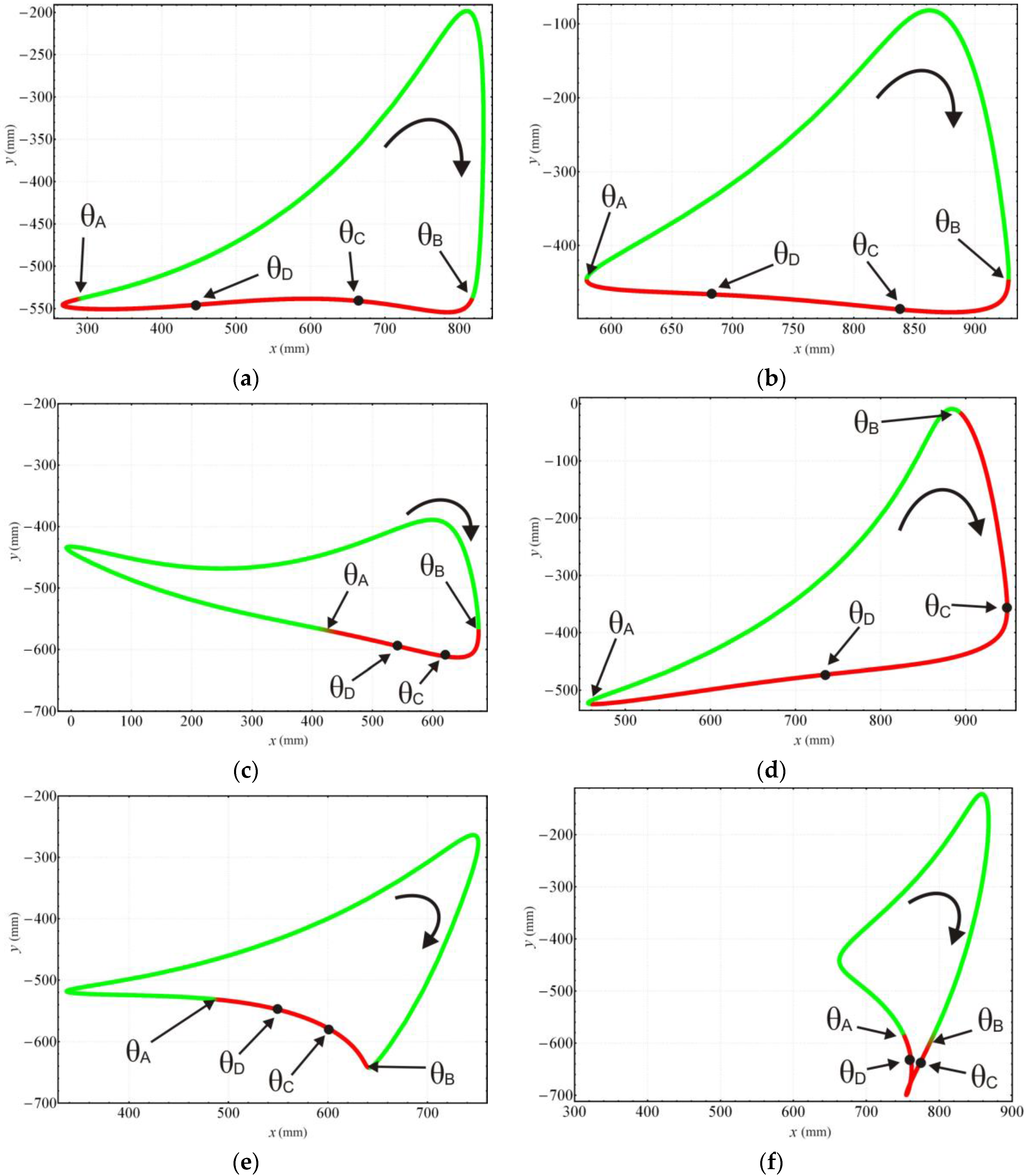
, and the support leg and the transfer leg can be switched depending on the value of the angle. For the purpose of defining the order of the states through naming convention, we define the states of the transfer leg “Left-Fore”, “Right-Hind”, “Right-Fore”, and “Left-Hind” as “Phase 1”, “Phase 2”, “Phase 3”, and “Phase 4”, respectively. The switch angles of the support and transfer legs for gaits are presented in
Table 2 and
Figure 3 where the support state starts from angle
and ends at
to switch to transfer state.
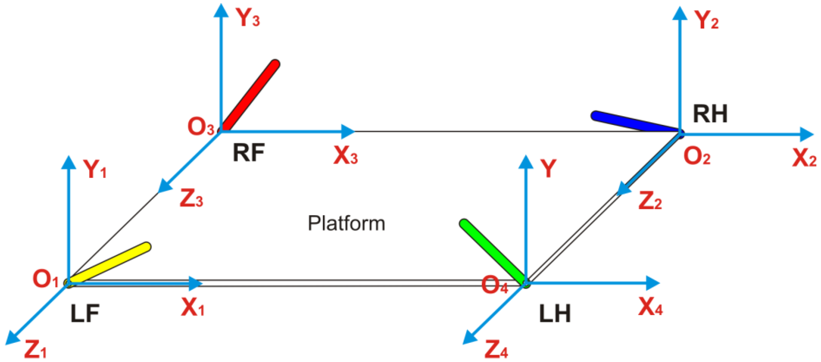
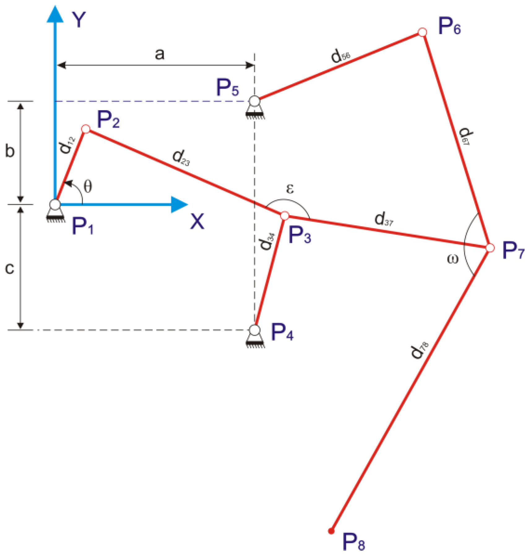
Figure 4 shows the coordinate systems used to analyse input angle for the four legs.
Figure 5 shows the relationship between input angles
and
and the position of the leg for standard curve trajectory. The other two states,
and
, are calculated as follows:
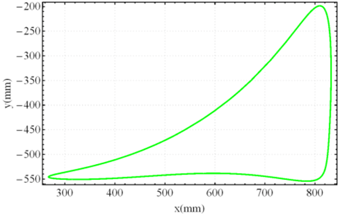
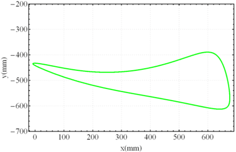
For the “Standard curve”, and are defined by the input angle at points on the curve that have the same height with the uppermost point at the bottom of the curve. For the “Digitigrade locomotion” and “Hammering motion”, due to short contact to the ground, and are chosen by the angle of curvature at 20% of the total height of trajectory from the lowest point of the gait pattern.
In the case of “Digging motion”,
is defined by the angle of curvature at the lowest vertical height point of the gait pattern and
is defined by the angle of curvature of the middle point on the left of the gait pattern. For “Jam avoidance”, the start of the support phase is chosen at the rightmost point on the curve with corresponding input angle
while the end of this phase is placed at the leftmost point with angle
. And finally, for “Step climbing”,
and
are determined by the time the leg starts to climb on step and release of the leg from the step respectively as shown in
Figure 3.
The initial states of each leg are presented in
Table 3 (column “Phase 1”) and the final states (Phase 4) of each leg are the initial states of the next cycle.
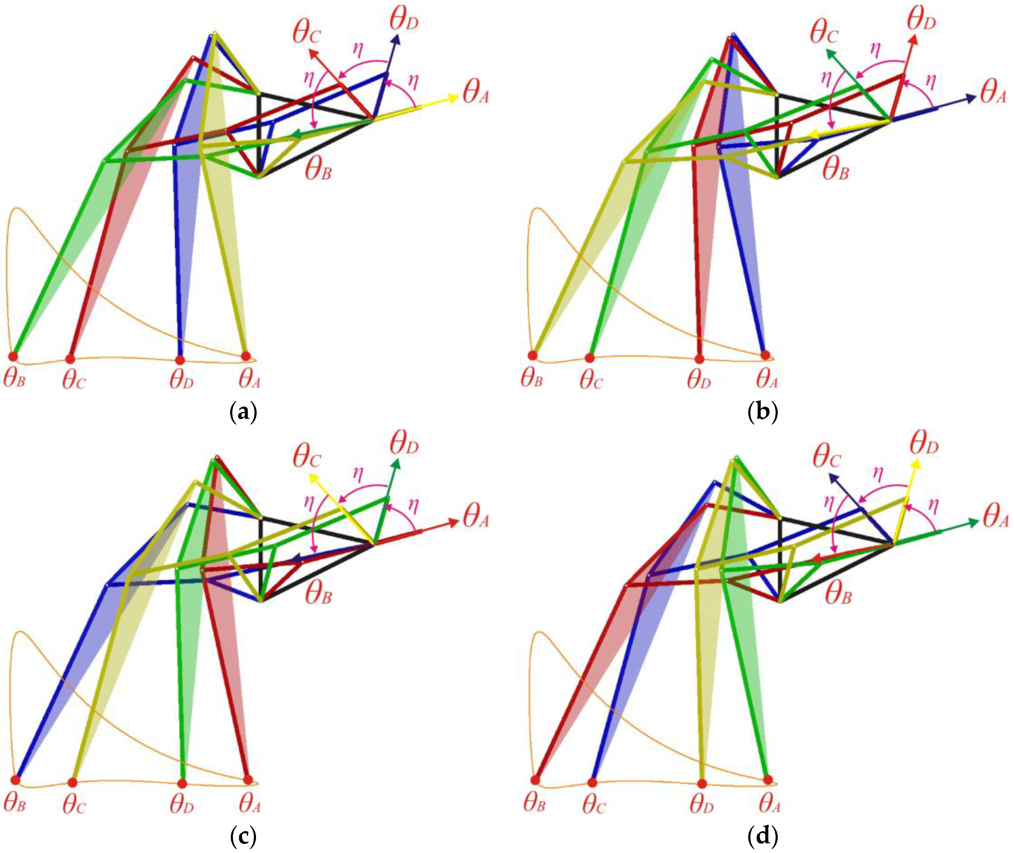
Figure 6 shows the four leg walking synchronization for all the four phases. The position of each leg is clearly shown for the standard Klann curve.
Figure 7 shows all possible states of stable walking of a Klann standard trajectory with half-phase shift. By using cubic polynomial interpolation for all trajectories generated that are shown in
Figure 8, it can be seen that the transition of the input angle between phases over time is very smooth and without any sudden change, which helps to avoid impact on the actuators and linkages.
5. Static Stability Analysis of Gaits
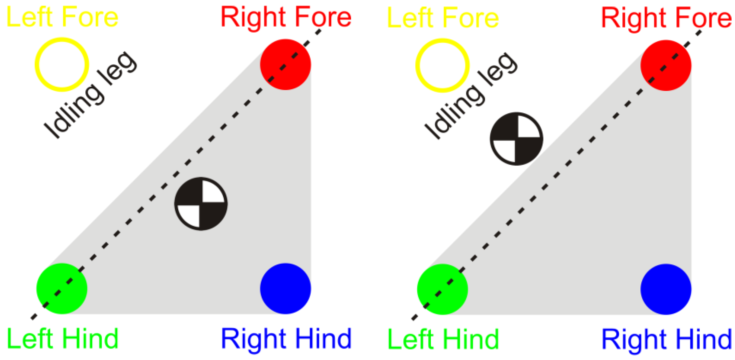
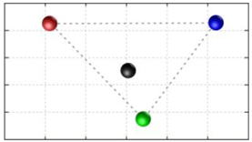
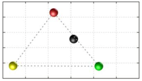
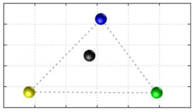
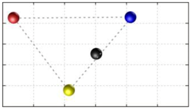
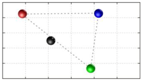
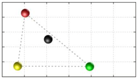
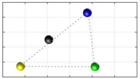
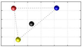
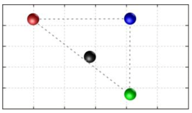
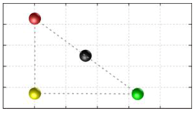
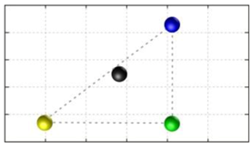
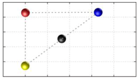
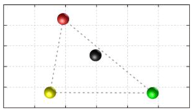
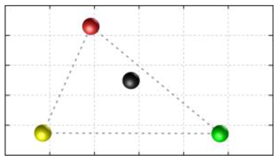
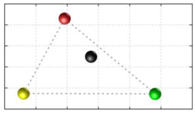
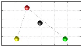
In this section, we discuss the static stability of walking for the quadruped robot. The quadruped robot walks with three support leg and one transfer leg. If the center of gravity (COG) stays inside the supporting leg polygon, the robot is stable, and in the case of the quadruped robot, its supporting leg polygon is a triangle. In addition, four kinds of triangles can exist as shown in
Figure 9. From
Figure 9, it is confirmed that all supporting leg polygons consist of two legs in opposing corner and one other leg. Whenever the COG of the robot is placed on its center, the positional relationship between a line on the two legs in opposing corners and the COG has an influence on its static stability.
Figure 10 shows two situations of static stability, stable and unstable condition.
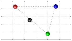
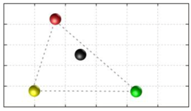
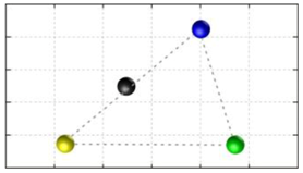
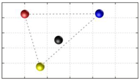
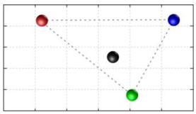
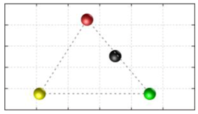
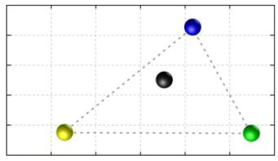
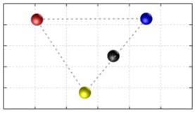
Next, we will evaluate the static stability of the whole platform at a specific moment of each phase corresponding to the proposed gaits. The relationship between the center of gravity (COG) and the three support legs of the robot is presented in
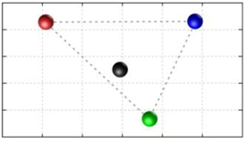
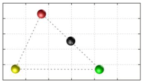
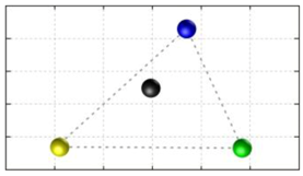
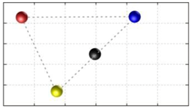
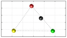
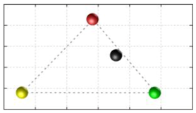
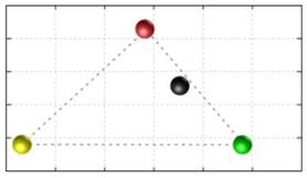
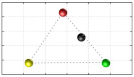
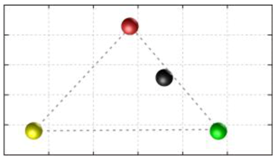
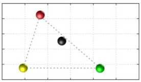
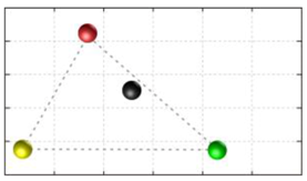
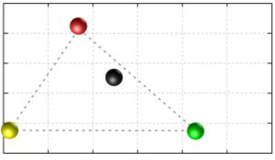
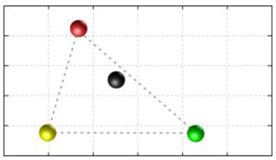
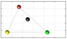
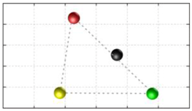
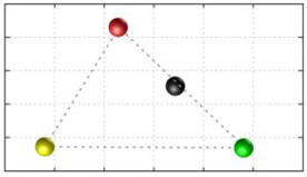
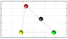
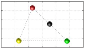
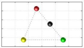
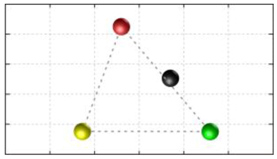
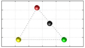
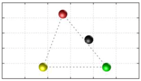
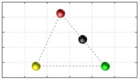
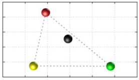
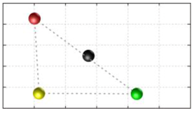
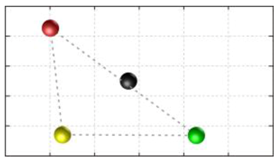
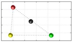
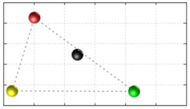
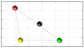
Table 4 where the black points denote the COG of the robot, the yellow points, green points, blue points and red points represent the contact points of the support legs with the ground, and the gray line shows the static stability zone. All the COG results are automatically calculated and projected using the software Autodesk Inventor. These static stability results show that in most cases, the proposed approach generates sufficient conditions to keep the platform stable. This is observed by the position of the center of gravity inside the static stability zone.
Although the entire COG results are inside the static stability zone, low stability margins are witnessed in
Table 4 when computed by known evaluation methods [
23,
24,
25]. For such narrow stability margins, there are several solutions to improve stability while still maintaining simplicity of control. One example is to add an inverted pendulum to act as a counterweight that moves oppositely to the transfer leg direction. In any case, this subject warrants further research.
6. Characterization of Transformation
In the previous sections, we have shown stable walking by the Klann reconfigurable platform using phase synchronization, trajectory generation, as well as analysis of the static stability. The next challenge is to develop a stable transformation. Some transformation methods for the multi-legged robot are known, such as transforming on the spot [
24] or transforming during walking [
25]. In this paper, we implement both these transformation methods on our reconfigurable Klann robot. The first method (“Static Transformation” in this paper) will transform all four legs of the robot at the same time while the robot is in rest state. This will be an advantage for the robot when transforming in a small space as well as keeping the robot stable because no leg swings over the ground. For the second method (“Transformation in Walking” in this paper), the robot transforms leg by leg in its transfer phase while walking in order to save time and perform a high maneuverability. Cubic polynomial interpolation is also applied to both methods to provide a smooth transformation by substituting the initial and final state into the trajectory generator in the same way as
Section 4. For this case, not only the input angle of the driving link but also the link dimensions have to be calculated through trajectory generation Equation (1). Let us define
shown in
Figure 11, as the angle of the driving link of leg
,
as the length of the changing links (
for “Jam avoidance” to “Digging motion” in this paper) of leg
, and
as the offset height of each leg after transformation. Moreover,
and
represent those parameters after transformation.
6.1. Transformation I—Static Transformation
In this method, the robot performs a transformation in resting state, where all four legs transform at the same time and the whole platform can change the vertical height due to the characteristics of different gaits. In addition, the robot transforms under the state that all legs contact the ground to improve the stability with the following procedure:
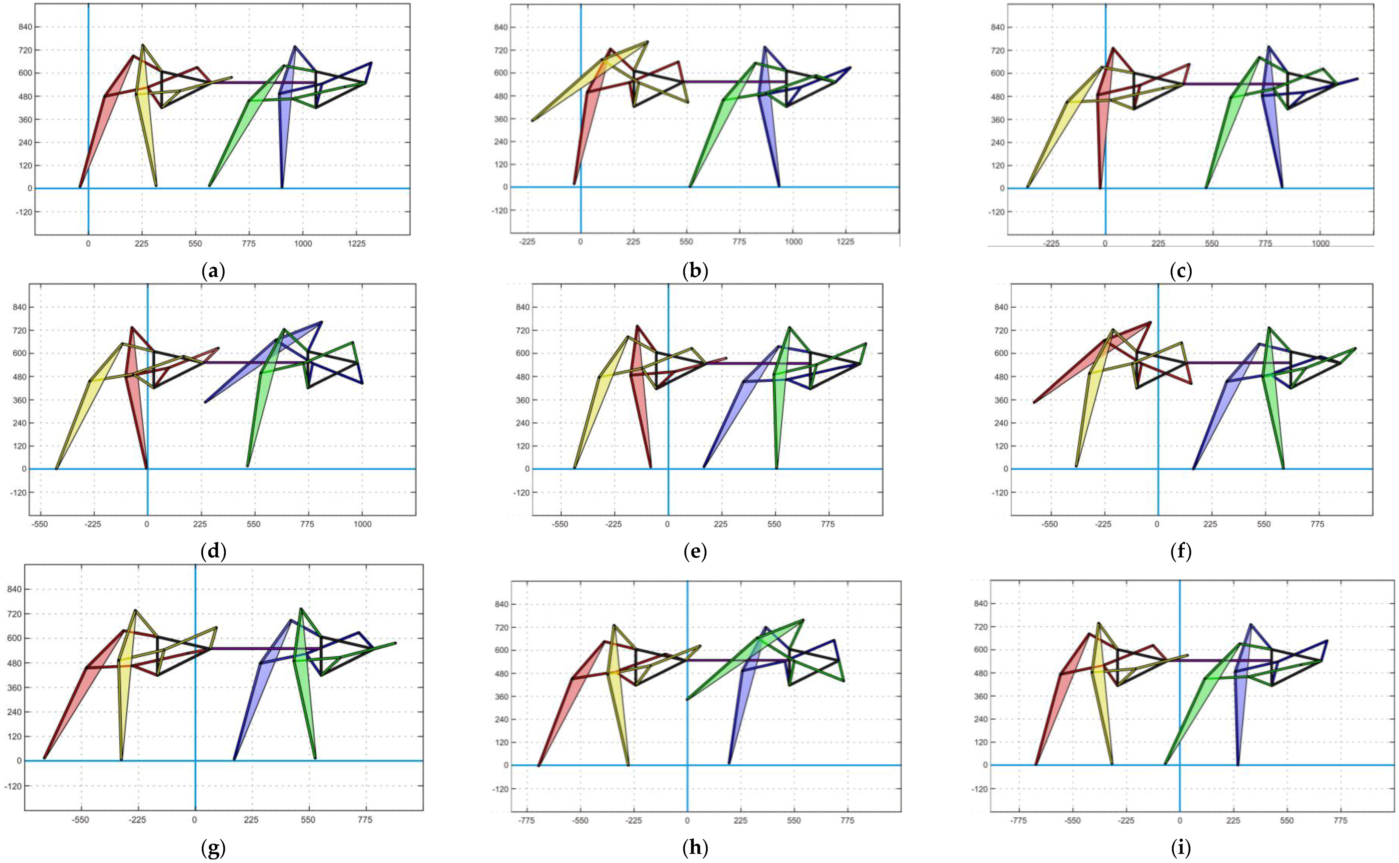
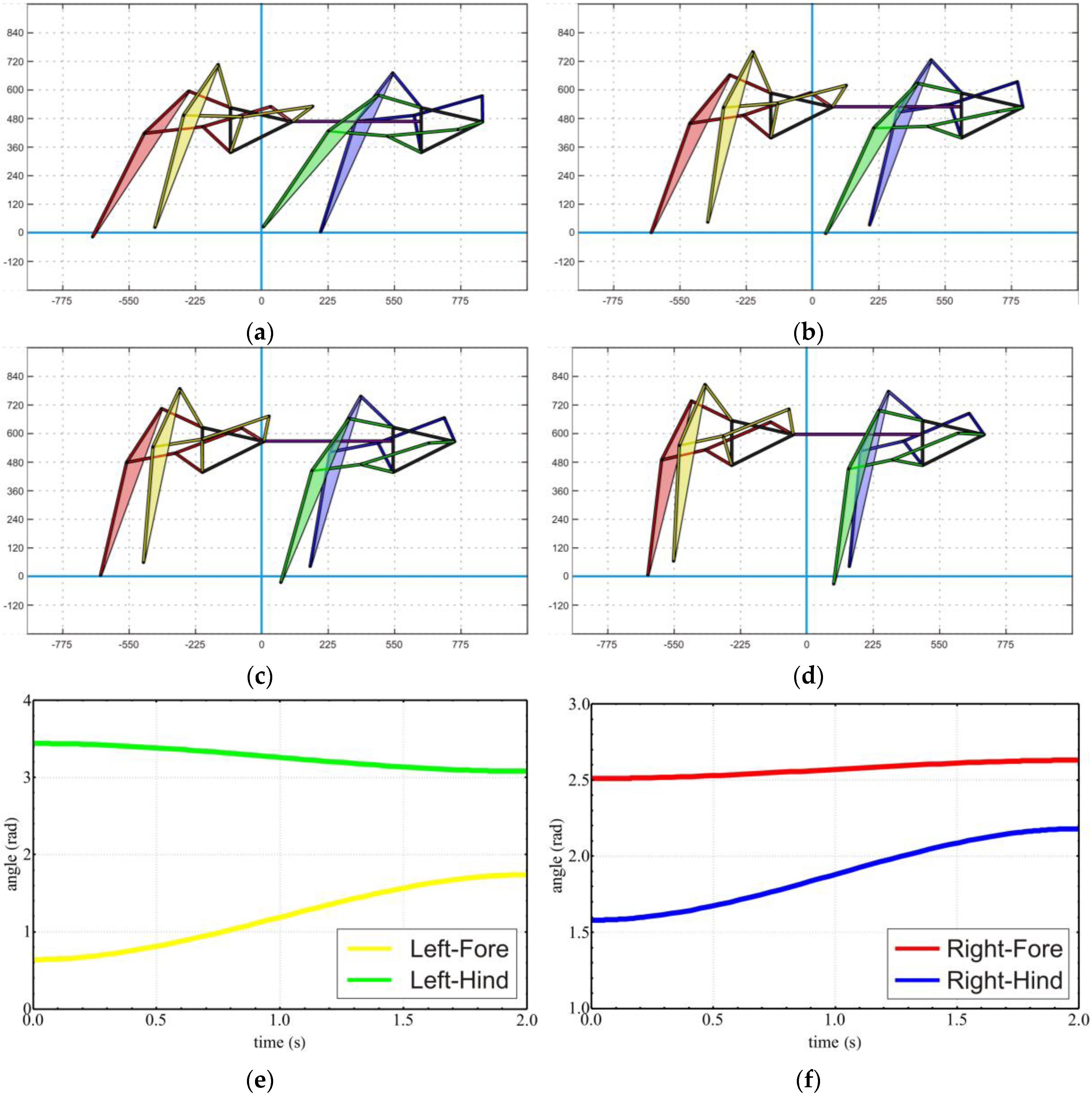
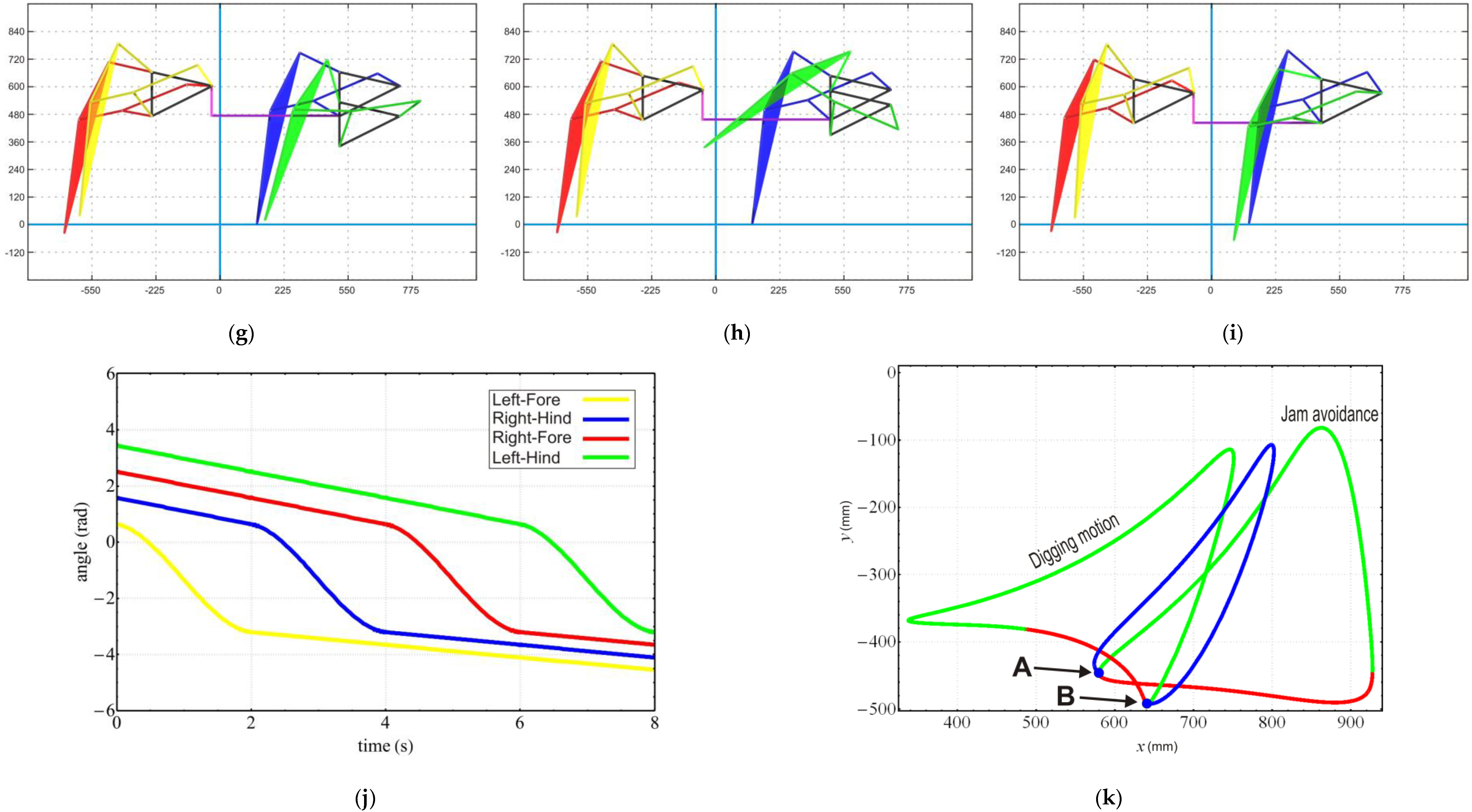
Figure 12a–d shows the transformation from Jam avoidance to Digging motion as an example following several steps presented in [
11] without the high compensation step. Trajectory generation is implemented for the input angle changing process from
to
and link dimension
to
with
shown in
Figure 12e,f.
6.2. Transformation II—Transformation in Motion
In this method, basically we combine walking phase synchronization together with transformation leg by leg. The transformation is applied when the leg swings over the ground to switch from support to transfer phase using trajectory generation designed in
Section 4 and
Table 3. Since the gait pattern before and after transformation is mixed, height difference between the four support legs will become large. In such cases, the linear height compensator is used to prevent undesired floor contact of transformed leg.
In our previous study [
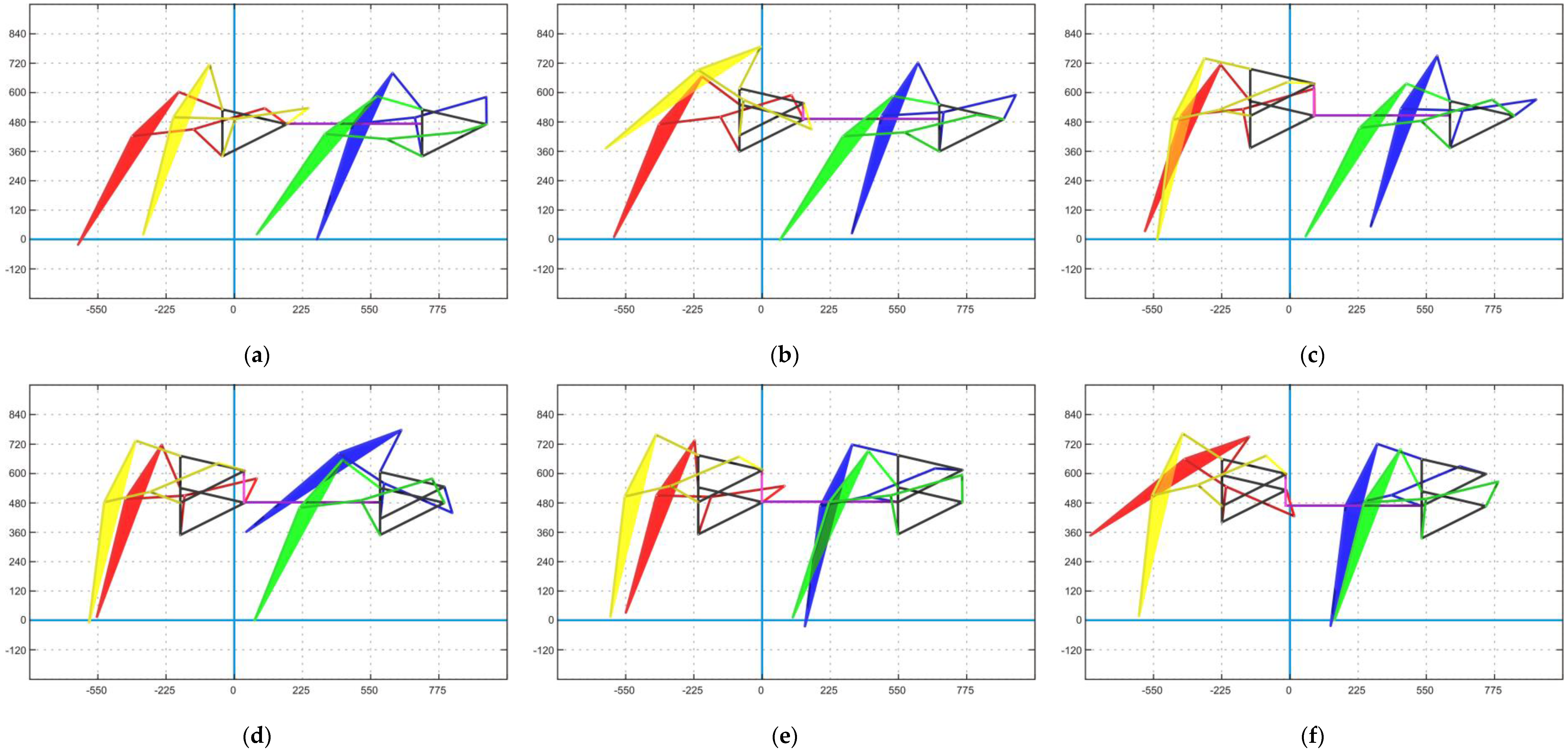
11], the height of the whole leg was decided by the angle of the driving link and the link dimensions since the leg transformed between the lowest points of each gait pattern. On the other hand, in this study, the height offset for the transforming leg is also applied by the designed trajectory generator. The trajectory of the whole transformation process from Jam avoidance to digging motion is shown in
Figure 13k. Before transforming, the leg moves with Jam avoidance trajectory until it reaches point “A”, also known as the start point of the transfer phase of Jam avoidance. Then, the transformation process is started with changes in the input angle from
of Jam to
of Digging as well as the transforming links dimensions and height offset. During transformation, the trajectory of the leg is illustrated as the blue line in
Figure 13k. The process ends at point “B”, which is also the beginning of Phase 2 of Digging motion, to generate a new trajectory. This process is repeated for the other three legs with the sequence mentioned in
Section 4 and
Table 3.
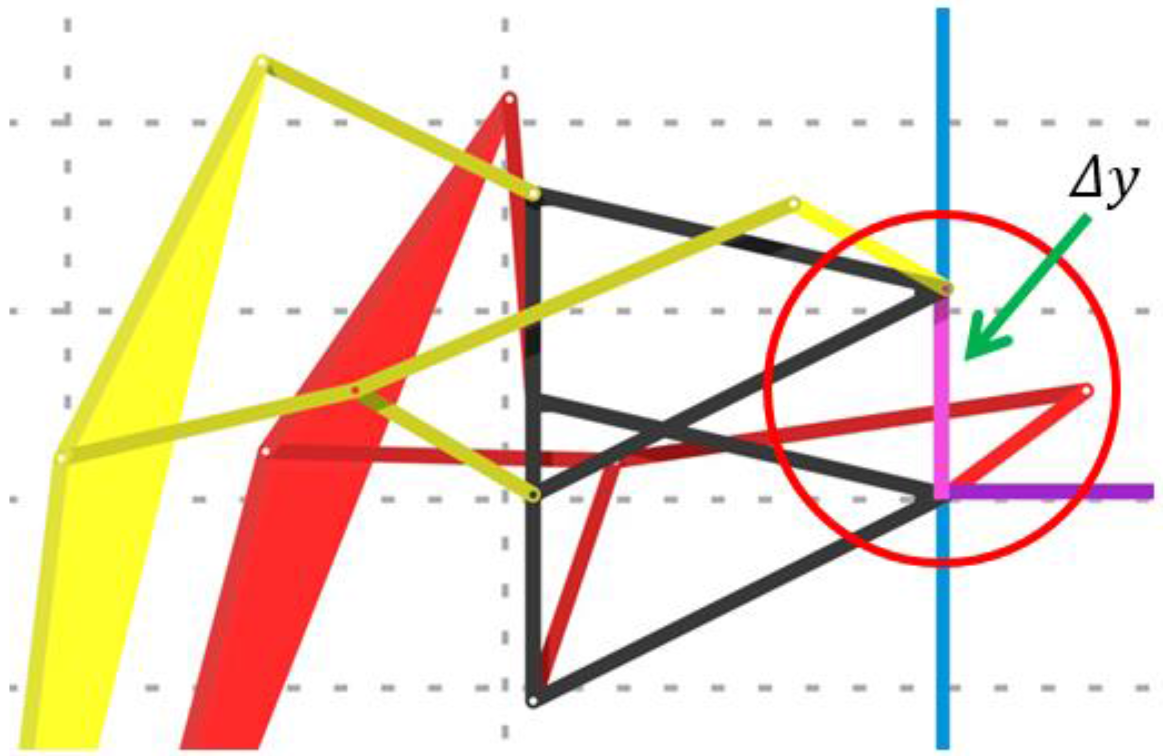
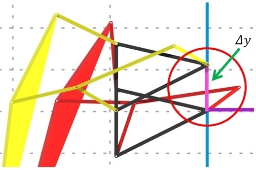
Notice the pink line connecting the Left-Fore leg’s frame with the body platform in the red circle in
Figure 13 and
Figure 14. It represents height offsetting of the linear slider to prevent undesired floor contact during transformation (
). The length of this line depends on which transformation is performed between two patterns in a set mentioned in
Table 1 (Standard curve, Jam avoidance, digitigrade motion, Digging motion, and Hammering motion).
7. Static Stability Analysis of the Transformation
The static stabilities for two types of transformation are evaluated. We first discuss the stabilities of the static transformation. The main point of static transformation stability is to transform from the initial state of all four legs shown in
Figure 3 and
Table 3. Since the robot transforms under the state that all legs are contacting with the ground, the robot can keep its static stability continuously during transformation. In this case, height difference between the leg before and after transformation will be the same for all four legs, therefore, undesired floor contact is eliminated and height offset is not necessary.
Next, stabilities of the transformation in walking are reviewed. Relationships between the support legs and the COG of the platform for all available transformations are automatically calculated and projected from top to bottom using the Dynamic Simulation tool in Autodesk Inventor in an ideal environment, without any external force application on the robot and all parts made from the same material with the same characteristics.
Phase 1 and Phase 4 of this transformation method has similar stability as shown in
Table 4 because all support legs are in the same pattern. Hence, stability analysis is needed only for Phase 2 and Phase 3. Here, only static stability analysis is considered for Phase 2. The initial and final state of the transfer leg in the transformation in walking is shown in
Table 5. In
Table 6, black points represent the COG of the platform, and yellow points, blue points, green points, and red points represent the contacting point of the support legs. The gray lines show the static stability zone. From
Table 6, it can be assumed that the transformation in walking is stable by the proposed method because the center of gravity stays inside the static stability zone, except for some situations marked with (*).
