Article

Ray-Casting-Based Trajectory Generation for Industrial Robots in Manufacturing Operations

by
Eduardo Fuentes-Fierro
,
Erardo Leal-Muñoz
* and
Eduardo Diez
Departamento de Ingeniería Mecánica, Universidad de La Frontera, Avenida Francisco Salazar 01145, Temuco 4811230, Chile
*
Author to whom correspondence should be addressed.
Robotics 2026, 15(7), 132; https://doi.org/10.3390/robotics15070132
Submission received: 3 April 2026 / Revised: 20 May 2026 / Accepted: 26 May 2026 / Published: 10 July 2026
(This article belongs to the Topic Smart Production in Terms of Industry 4.0 and 5.0)

Abstract

This paper proposes a set of trajectory generation strategies for industrial robots that use ray-casting over the workpiece CAD model for various manufacturing operations. By employing ray-casting on a triangular-mesh representation of the production part, points can be generated across the entire surface without extracting geometric features such as curves, edges, or planes. This approach enables the development of diverse point-generation methods with distinct characteristics, adaptable to the specific requirements of each part and manufacturing process. The developed algorithms achieve results comparable to existing robot programming methods, and, when integrated into the specialized offline programming environment, they enable flexible trajectory generation for operations such as sanding, milling, adhesive deposition, and painting. Finally, these trajectories are automatically exported in a syntax that ensures rapid integration of the point sequence into a base program compatible with an articulated robot controller. The results show that the proposed methods can effectively generate trajectories for sanding and milling using two different robots.

1. Introduction

For manufacturing companies, industrial robotics is a resource that enables the automation of production operations, resulting in more efficient processes and, due to robots’ consistency in executing tasks, improved product quality [1]. However, robot programming remains a complex task that requires skilled personnel with experience in this technology. Current programming capabilities of robotic systems generally exhibit limitations when assigned different tasks, particularly when new production parts are introduced or when changes occur within the processes. These changes may involve variations in instructions depending on the part geometry or its overall orientation within the workspace, requiring programmer intervention. In recent years, alongside the rapid growth of industrial robotics, there has been a growing interest in developing new tools that facilitate programming and enable faster setup with lower personnel qualification requirements.
Methods for programming articulated-robot trajectories are classified as online (manual) or offline programming (OLP). Manual programming has several disadvantages compared to OLP, as it requires experienced personnel to operate the articulated robot within the workspace. This reduces production capacity by consuming time for programming, which increases according to the complexity of the operation. For instance, manually programming welding trajectories for manufacturing large-vehicle structures can take up to 8 months, whereas the actual welding process takes approximately 16 h [2]. Despite this, manual programming still predominates in the industry, as software costs and the need for specialized personnel pose barriers to automating operations such as trajectory generation, resulting in significant production downtime.

1.1. Robot Trajectory Generation

Robot trajectory generation is an extensively researched topic. A variety of methods exist for path planning, such as the Dijkstra algorithm [3], its A* variation [4], Rapidly-exploring Random Trees (RRT) [5], genetic algorithms [6], and other artificial intelligence-based models [7,8]. These methods primarily focus on finding optimized, shortest, or energy-efficient paths, which are mainly applied in mobile robotics. On the other hand, path planning for manufacturing operations, such as sanding or milling, requires optimization based on different criteria; for instance, ensuring the trajectory covers the entire workpiece surface or guiding the tool along specific zones. Consequently, conventional methods are not directly compatible with manufacturing applications, presenting a significant challenge for robot trajectory generation in discrete production contexts.
Robot trajectories for manufacturing operations involve specific process variables, making the development of generalized programming methods difficult. Existing literature includes various studies addressing trajectory generation for machining, painting and adhesive deposition operations; however, these solutions are particular to specific processes.
One of the most widely studied methods for trajectory generation is the slicing technique. This method involves generating a series of cutting planes throughout the workpiece and identifying the intersection points between these planes and the surface geometry, whether in STL format or as a point cloud. In manufacturing, this approach has been utilized in operations such as sanding [9,10], milling [11] and painting [12].
In a study by Schneyer et al. [13] on sanding trajectory generation, surfaces with various feature types are addressed by designing motion strategies for specific segments or geometries. Each segment is parameterized based on the type of curvature and other distinctive geometric characteristics. Furthermore, each segment is associated with a specific motion strategy. Subsequently, depending on the surface to be processed, the algorithm searches for similarities between the production workpiece and the previously characterized segments to generate a trajectory. Schneyer et al. perform this process iteratively until a sanding trajectory is generated for the entire surface.
Leth and Petersen [14] investigate edge identification in STL models of the workpiece to generate a continuous trajectory along those boundaries using NURBS (Non-Uniform Rational B-Splines). Shen et al. [15] investigate a similar approach, employing an erosion-based method for a metal painting application to populate the surface with points, which are then connected using NURBS curves.
In the welding application presented by Bedaka and Lin [16], the user must manually select the edge to be welded to generate a trajectory. This approach shows that an OLP system does not inherently imply autonomy at every programming step, thereby leveraging the operator’s flexibility.
Another method for trajectory generation is the one developed by Nieto and Lin [17] for spray painting. In this approach, starting from a workpiece point cloud, a bounding sphere is generated from many points. These points iteratively reduce their radius until they intersect with the surface geometry. Finally, the points that contact the geometry are used to generate the painting trajectory.
While the described methods perform effectively in their respective applications, their operating principles vary significantly, hindering their integration and combination to generate specific trajectories within a single offline programming environment.

1.2. Ray-Casting

Ray-casting is a fundamental technique in computer graphics and computational geometry that casts a ray from a point of origin in a specific direction to detect intersections with objects in both three-dimensional and two-dimensional spaces [18,19]. Due to its low computational cost and versatility, ray-casting is used in a variety of applications across diverse fields, ranging from computer graphics generation and environmental data acquisition to artificial perception, sensor simulation, video game development, virtual or mixed reality interfaces and robotics.
In robotics, ray-casting has been employed in applications requiring environmental observation and information extraction [20,21], as well as for obstacle avoidance [22] by casting rays from multiple perspectives in hundreds of directions. The information gathered from each ray upon colliding with objects is then used to recognize environmental features and plan actions. For instance, Ali et al. [23] utilized a simulated environment to evaluate autonomous path-planning algorithms and methods for unmanned aerial vehicles (UAVs), in which ray-casting is used to compute distances to potential obstacles. Santos et al. [24] employed rays and a voxelized map to develop an autonomous exploration method for articulated robots. Furthermore, some methods specifically use ray-casting to find optimal trajectories, such as in the work by Bircher et al. [25] and Kim et al. [26], where the technique is used to register visibility zones and detect obstacles. Despite the various applications that have utilized ray-casting in robotics, this technique has not yet been directly applied to robot trajectory generation for manufacturing operations.
This paper presents a methodology for trajectory generation within an offline programming environment, designed to apply ray-casting-based trajectory generation methods, referred to as R-Methods, by employing different application logics according to the desired trajectory type. These methods achieve results comparable to those reported in the literature, with the advantage of being designed with a generalized logic. This allows the developed methods to be used for different applications and even combined to obtain specific trajectories. Consequently, the developed environment is presented as a valuable tool that enables programmers to generate trajectories for various manufacturing operations easily.

2. Materials and Methods

Manufacturing operations such as sanding, milling, or painting essentially require moving a specific tool across a workpiece, generally tracing its surface. To automate these processes using robots, it is necessary to consider certain constraints and conditions to generate valid trajectories for each operation. Depending on the manufacturing task, trajectories must satisfy characteristics such as tool orientation relative to the part, surface coverage, or maintaining a specific distance between the tool and the workpiece. From a kinematic perspective, these manufacturing operations share common constraints and conditions. For instance, sanding and adhesive deposition trajectories both require a tool to traverse a surface to cover a specific area. Following the same example, a painting trajectory would exhibit similar characteristics but must maintain the tool at a determined offset from the surface. This observation implies the existence of generic sequences or motions that, by adjusting certain parameters, can be adapted for multiple applications. Considering these shared process characteristics, this study focuses on developing a set of methods, called R-Methods, grounded in ray-casting.

2.1. Offline Programming Environment

To implement and apply the R-Methods, an OLP environment was developed using the Unity game engine [27]. This environment enables the visualization of CAD models, the representation of operations within reference frames, and the definition of user interface (UI) elements to facilitate each function. Unity was selected for this development due to its compatibility with 3D models, integrated ray-casting functions, and its support for modular, scalable programming. To implement a functional OLP environment oriented toward R-Methods, it is essential to have mechanisms for loading, visualizing, and manipulating the 3D model of the production workpiece. Although Unity does not natively support CAD formats, it facilitates the reconstruction and rendering of triangular meshes obtained from STL files, which are widely used in industrial settings. Once the geometry is loaded, the system must manage point sequences that encompass not only the operation-specific trajectories but also the auxiliary and transition points needed to approach the part from an appropriate orientation, retract safely, and create intermediate waypoints to avoid collisions. A 3D scene that accurately matches the actual workspace configuration is required to validate that these trajectories have been correctly generated and that no erroneous or unreachable positions exist. Specifically, points must be referenced to a common base frame, equivalent to the robot’s physical base, ensuring that the simulation maintains spatial coherence with the robotic cell. Approved trajectories must be recorded exclusively as lists containing the position and orientation of each point. This makes it possible to manage process variables such as force, speed, or motion types of the robot within a pre-existing base program, facilitating subsequent integration into specific script templates for different industrial robot brands. The workflow requires a UI that allows each functionality to be operated via buttons, panels and input fields for parameter adjustment and data visualization. Finally, the environment must be developed as a modular, scalable system capable of incorporating new R-Methods, expanding sequence management tools, and integrating with different robotic systems or cells, thus ensuring its long-term value and flexibility.
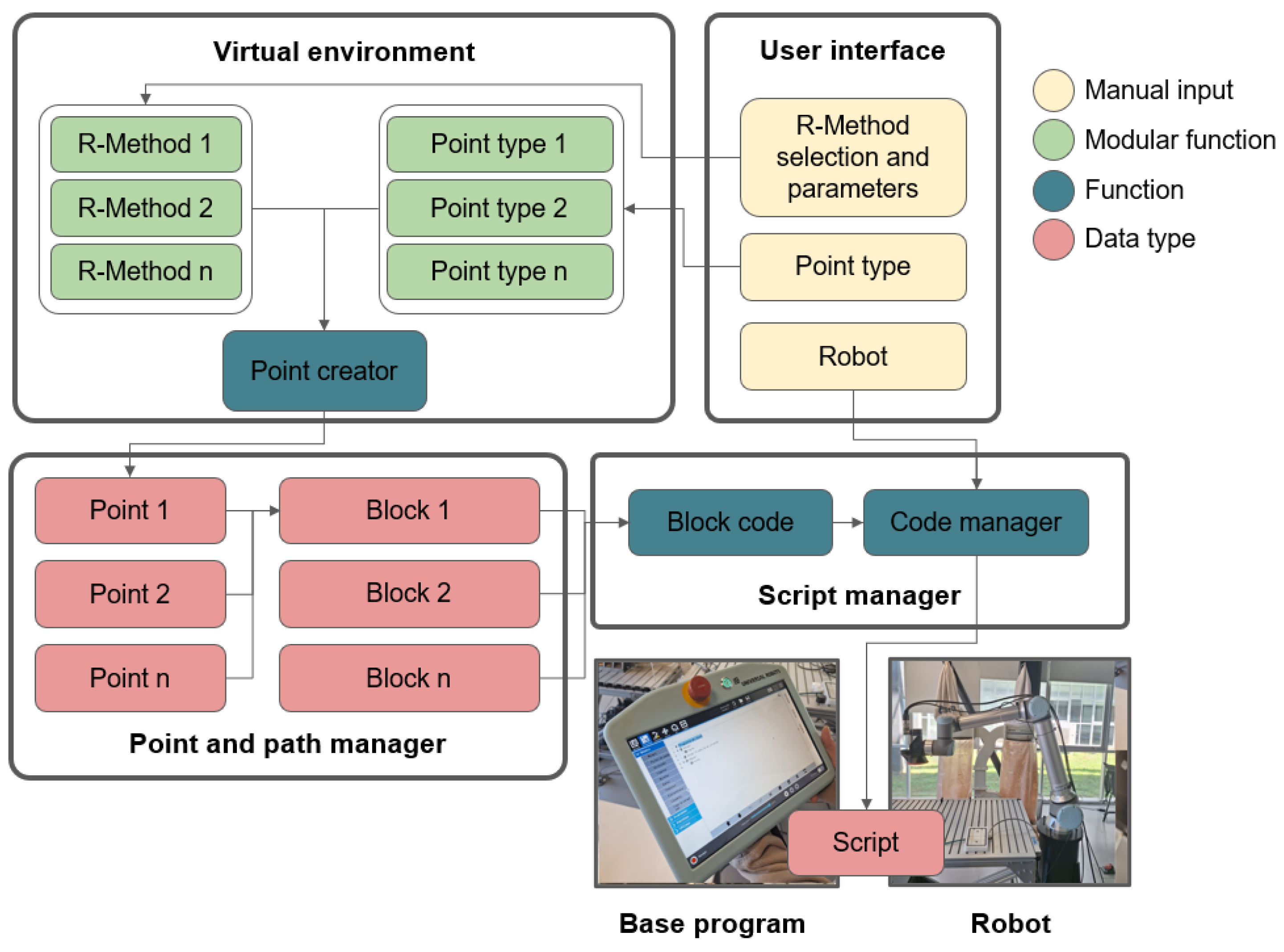
Figure 1 illustrates the interaction between the functions and data comprising the proposed solution. Specifically, the virtual environment allows for the selection of R-methods (along with their associated parameters) and different Point Types, which are defined as modular functions. These functions can be combined to generate the desired trajectories. Notably, adding or removing functionalities does not disrupt the standard workflow. By combining R-Methods with various point types, points can be generated directly based on the part geometry. These points can be grouped into blocks, allowing arbitrary separation of sequences for better trajectory organization. Finally, these blocks serve as the basis for code generation, enabling the automatic creation of programming scripts for a specific robot.

2.2. R-Method Development Logic

In this work, tool trajectories are considered sequences of points in space that describe the positions and orientations the tool must maintain to execute the process. To generate points using ray-casting, it is necessary to define an origin and a direction and to establish a triangular mesh representing the surface geometry. Equation (1) presents a function that describes ray-casting, where O corresponds to the ray origin, D to its direction and t to the distance from the origin along the ray.
R ( t ) = O + D t
Given that the concept of a triangular mesh is widely used in computing to represent geometric bodies, it is necessary to characterize the intersection of rays with triangles. To this end, one of the most commonly used algorithms is the Möller–Trumbore algorithm [28], which represents the intersection point, as shown in Equation (2), where V o , V 1 and V 2 are the vertices of the triangle; u and v are two elements of the triangle’s barycentric coordinates; and R is a ray defined by Equation (1).
R ( t ) = ( 1 u v ) V o + u V 1 + v V 2
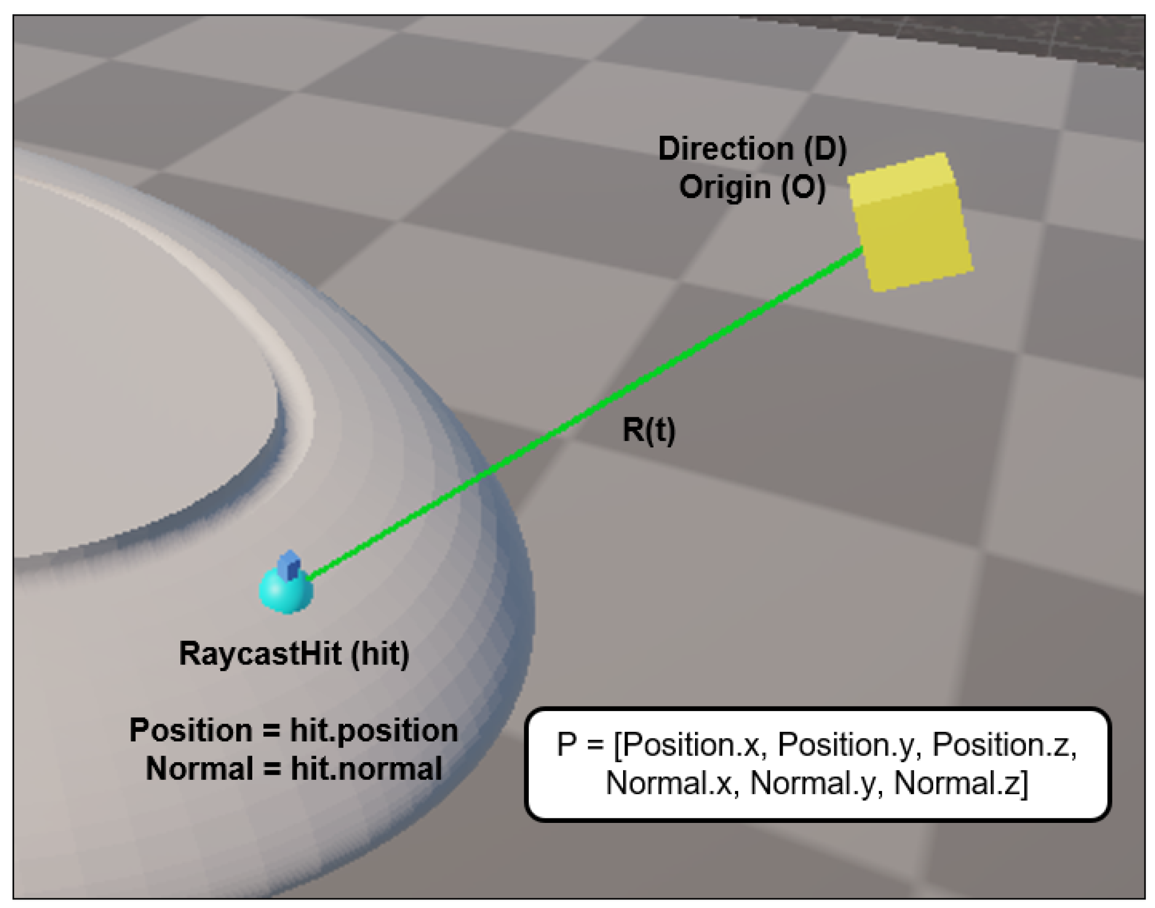
Based on this, it is possible to determine a specific point at the intersection between a given ray and a geometry composed of a triangular mesh. Once an origin and direction have been determined for casting a ray (Equation (1)), the ray can detect a collision with a surface, specifically with a triangle in the collision mesh. Through the Unity RaycastHit class, it is possible to reference this collision, which is conventionally referred to as a “Hit”. This collision object contains properties for both the position and the surface normal at the point where the ray intersects the geometry. This is illustrated in Figure 2.
The extracted information from the collision allows us to register points with the following format:
P = x , y , z , n x , n y , n z
In this format, [ x , y , z ] corresponds to the Cartesian coordinates of the point relative to the defined workspace origin, while [ n x , n y , n z ] represents the components of the surface normal at that point. By recording points in this manner within a list, the sequence executed by the robot is directly contingent upon the order in which the points were generated. Consequently, the trajectory can be constructed intuitively and sequentially, considering from the outset how the robot must execute the task from beginning to end. The main goal of the R-Methods is to offer a versatile way to generate trajectories for various applications, even allowing the combination of each method’s capabilities to obtain the desired sequences. Therefore, R-Methods must be generic enough to generate points on the workpiece, control tool orientation, and regulate the distance from the surface. Furthermore, it must be possible to define transition or auxiliary points without relying exclusively on the robot base program, thus avoiding additional operations in its internal configuration.

2.3. Experimental Setup

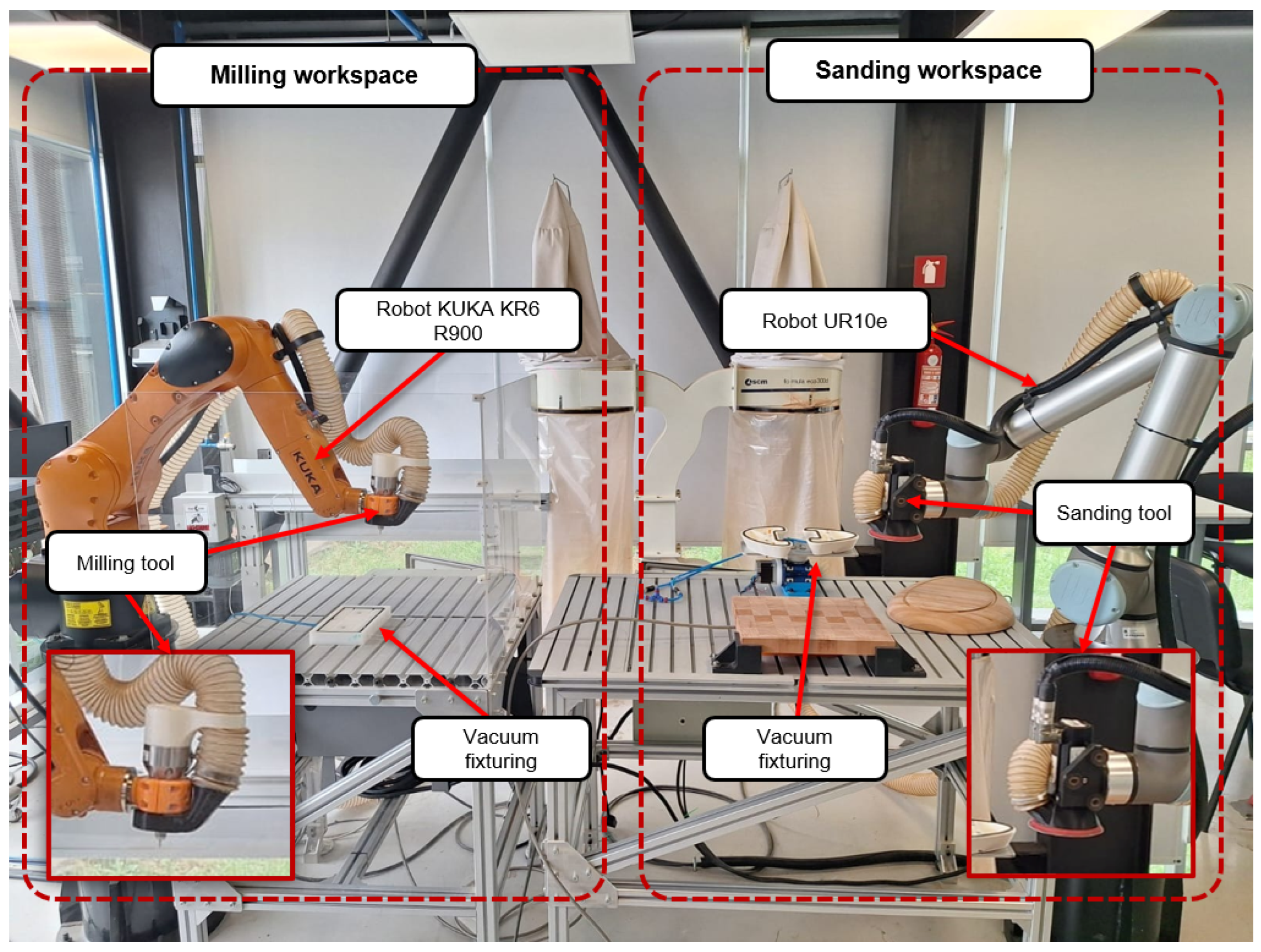
To evaluate the performance of the OLP environment and the developed R-Methods, a manufacturing setup consisting of two robotic stations is available, as shown in Figure 3. These stations were selected to validate trajectory generation in manufacturing processes with varying geometric and kinematic requirements. Also, to assess the computational performance of the R-Methods, temporal and spatial complexity are determined, and the latency of point generation is calculated. The first station features a KR6 R900 industrial robot (KUKA, Augsburg, Germany) equipped with a HES-210 high-speed spindle (Nakanishi, Kanuma, Japan) for milling tools up to 6.35 mm in diameter. The second station consists of an UR10e robot (Universal Robots, Odense, Denmark) configured for sanding operations using a rotary sanding tool powered by an AKM-23D servo motor (Kollmorgen, Radford, VA, USA), capable of utilizing 125 mm diameter sanding discs (3M Company, St. Paul, MN, USA) of various grits. Both stations are equipped with vacuum-based fixturing systems.
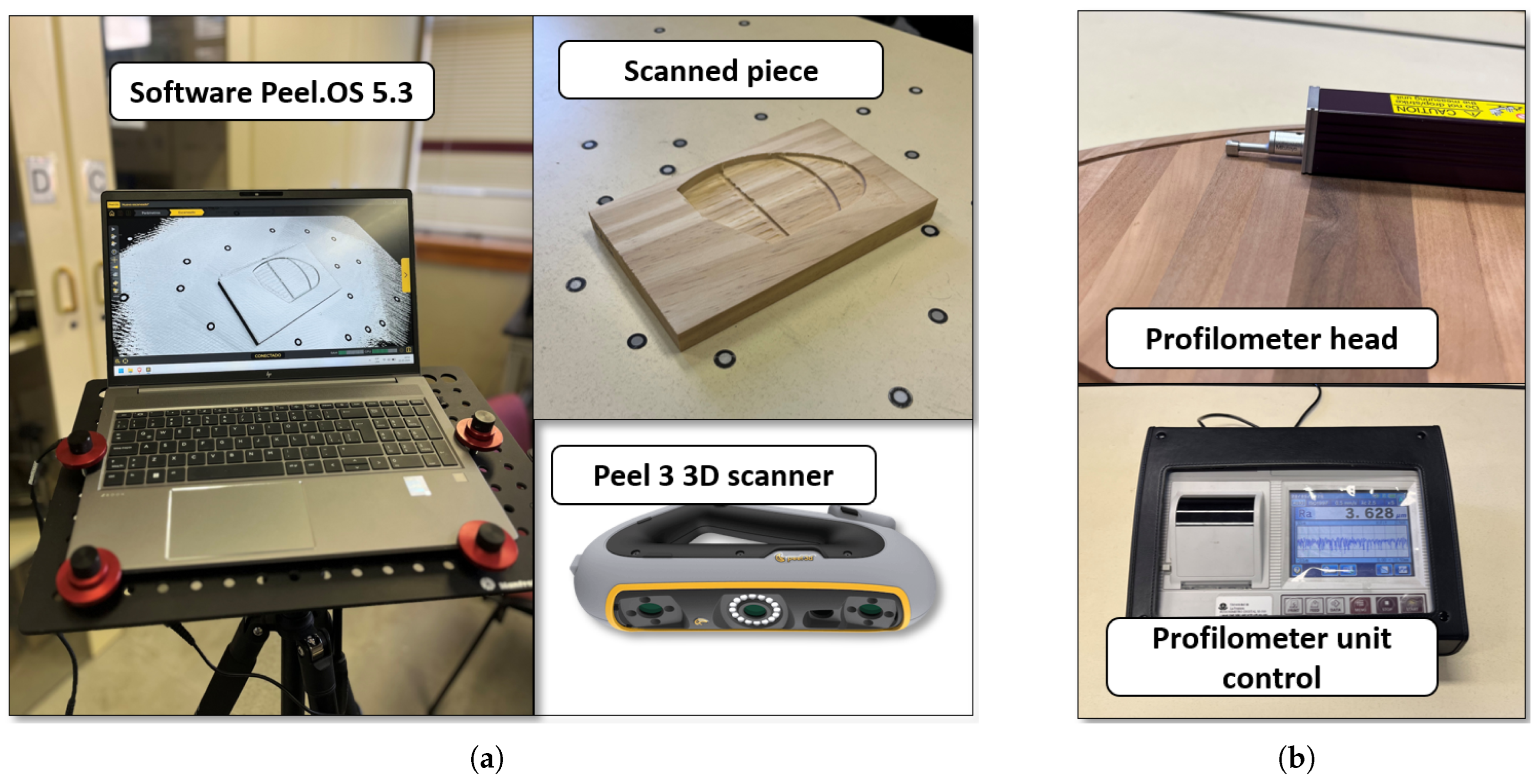
The use of these two platforms enables verification of the applicability of the R-Methods across different operations and with industrial robots from different manufacturers, ensuring that trajectories generated within the OLP environment can be consistently and flexibly transferred to the physical workspace. To further validate the effectiveness of the generated trajectories, a quantitative assessment of the workpiece quality is proposed. In the milling experiments, the dimensional deviations of the machined parts were evaluated through 3D scanning and comparison against the original CAD geometry, using the Peel 3 scanner (Creaform, Levis, QC, Canada) and the Peel.0S.5.3 scanning environment (Figure 4a). For sanding experiments, surface quality was evaluated by measuring roughness with a SJ-310 Surftest contact roughness tester (Mitutoyo, Kawasaki, Japan) (Figure 4a).

3. Results

This work presents four trajectory generation methods based on the same principle: ray-casting. These methods can be applied to manufacturing operations characterized primarily by moving a tool over a workpiece, such as sanding, milling, painting, or adhesive deposition. All methods being based on ray-casting not only ensures consistency in how points are obtained on the geometry but also facilitates the integration of different methods into an offline programming (OLP) environment, providing modularity and scalability. Furthermore, the environment can generate programming files for the UR10e and KUKA KR6 robots from the calculated trajectories.

3.1. Trajectory Programming Workflow

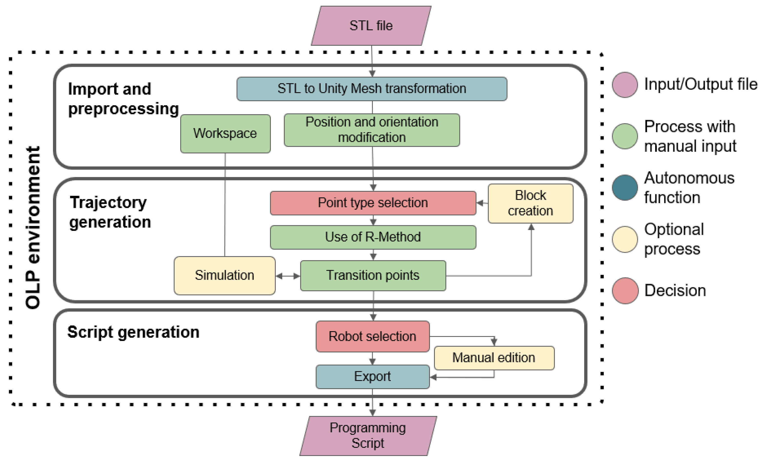
Figure 5 illustrates the proposed workflow for using the OLP environment, which consists of the following main stages:
  • Import and pre-processing: In this stage, an STL model can be loaded and visualized within the user interface, and its position and orientation can be modified according to the actual work environment. Parameters of the physical setup where the robot and workpiece are located must be considered, including kinematics, potential collisions and workspace volume, to ensure that the generated trajectories can be executed by the robot. The environment creates points and trajectories relative to a base frame or origin that must coincide with the real-world workspace and workpiece location.
  • Trajectory generation: This stage allows for the configuration of point types and other parameters that determine the characteristics of the trajectories generated by the four developed R-Methods: “R-Click”, “R-Slice”, “R-Rain”, and “R-Box”. To organize point sequences for robot paths and the specific manufacturing operation, auxiliary or transition points can be generated, and different sequences can be partitioned into blocks, which can be configured independently in later stages. Additionally, an optional kinematic simulation of the robot executing the trajectory can be performed to ensure that no erroneous points have been generated and that the intended movements are followed.
  • Script generation: In this stage, a programming script for the UR10e and KUKA KR6 R900 robots can be generated from an integrated base template, defining the points and motion functions in the appropriate syntax for each robot. This script can be edited in the OLP environment before export if a user needs to make manual changes. Finally, the generated script can be integrated into the base program of the aforementioned robots.
Figure 5 illustrates the workflow of the offline programming environment, which is structured into the modules of import and pre-processing, trajectory generation, and script generation. Within this workflow, several types of functional elements are distinguished:
  • Input and output files: The system utilizes an STL file corresponding to the production workpiece and generates an industrial robot programming script as a result.
  • Processes requiring manual inputs: These are associated with functions that demand parameter entry by the user, such as the R-Methods and Transition Points.
  • Autonomous functions: These execute tasks automatically without requiring manual intervention.
  • Optional processes: These are intended for improved management and organization of the trajectories.
  • Decision stages: These correspond to the selection of variables that determine how other processes operate, such as the robot type selection for script generation.

3.2. R-Methods

The developed R-Methods comprise a set of point-generation strategies that use ray-casting from various geometric entities. Some of these entities are user-defined planes or bounding volumes relative to the workpiece geometry, enabling the creation of points in space along with their associated orientations. The logic employed by R-Methods provides the user with flexible, intuitive and parameterizable control over the definition of trajectories for the robot TCP (Tool Center Point). Each R-Method receives a set of parameters, such as the number of points, surface offsets, orientations, coverage angles, or spacing, enabling it to adapt to different manufacturing processes. Furthermore, the R-Methods share a common logic in defining Point Types (Surface, Fixed Surface and Distant), allowing them to be combined coherently within a single trajectory or chained to generate more complex paths. Thus, the joint utilization of different R-Methods significantly expands the space of possible trajectories, facilitating surface coverage, specific local operations and strategies tailored to the user and process requirements.
One of the developed methods is R-Click, which involves manually selecting points by clicking on the workpiece. Being the most direct method, it generates points from the user’s perspective toward the cursor location. The method projects the cursor’s two-dimensional screen position into the 3D workspace of the OLP environment, then casts a ray in the direction of the projection.
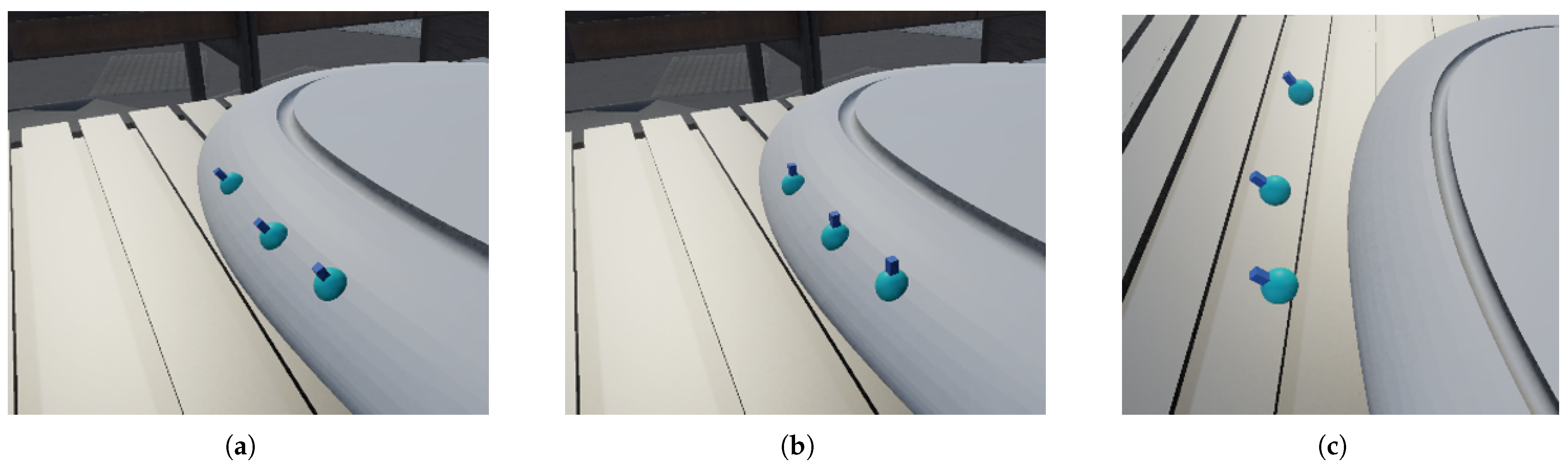
Figure 6 illustrates the three-point types that determine the characteristics of the points generated by the R-Methods. Figure 6a shows the Surface point type, which is placed on the workpiece surface and oriented along the surface normal. The Fixed Surface point type (Figure 6b) is positioned identically to the Surface point but with a fixed orientation, which, in the case of Figure 6, points upward. The last point type is called Distant (Figure 6c), which maintains the surface orientation but is offset from it by a specified distance. R-Methods utilize one of these three logics when generating points, depending on the application requirements.
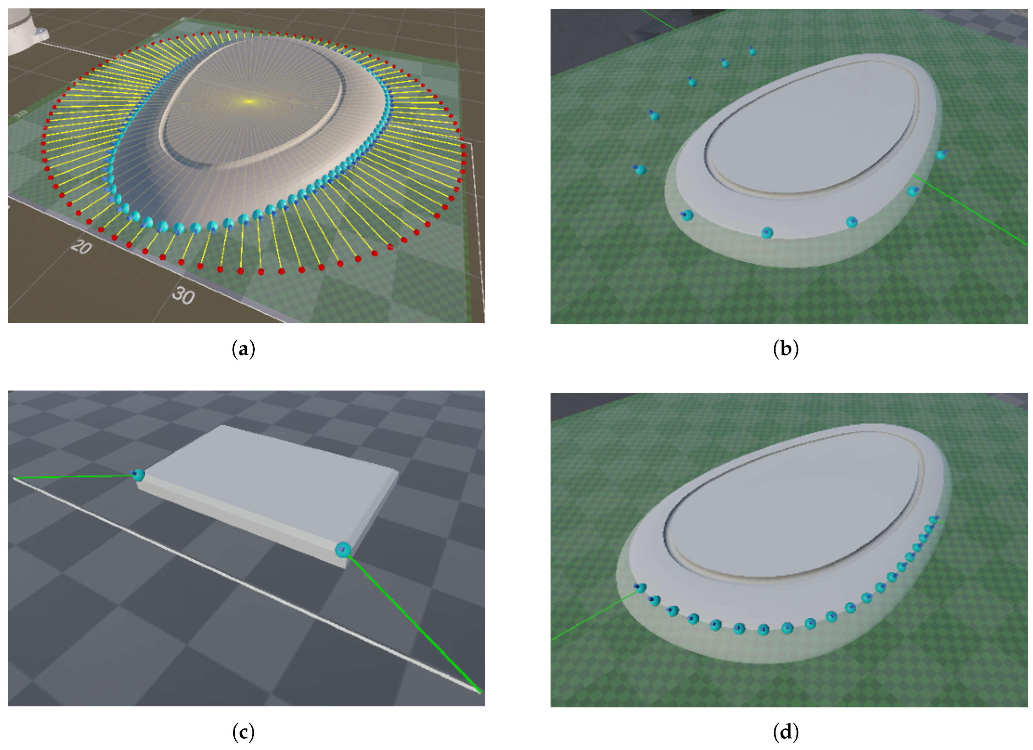
Based on the slicing logic described in the literature, the R-Slice method was developed to generate radial trajectories from planes. This method defines the cutting plane height, the number of points to generate, and an arc specified by two angles, thereby offering detailed control over surface coverage. The total number of generated segments, denoted as S , is determined by both the number of discrete points sampled along the trajectory and the defined arc, since each radial ray corresponds to a point generated within the defined angular interval. Consequently, the computational complexity of the method scales linearly with the number of segments, resulting in a time complexity of O ( S ) , where S represents the complete list of generated points and arc segments.
Figure 7 illustrates point generation using this method. Figure 7a visualizes 100 rays and their respective points generated radially to cover the entire surface of the workpiece. To demonstrate other applications of this R-Method, Figure 7b shows 10 Distant-type points within a 180° arc, Figure 7c displays only 2 entry and exit points on a chamfer, and Figure 7d shows 20 points on the surface within a selected 120° arc.
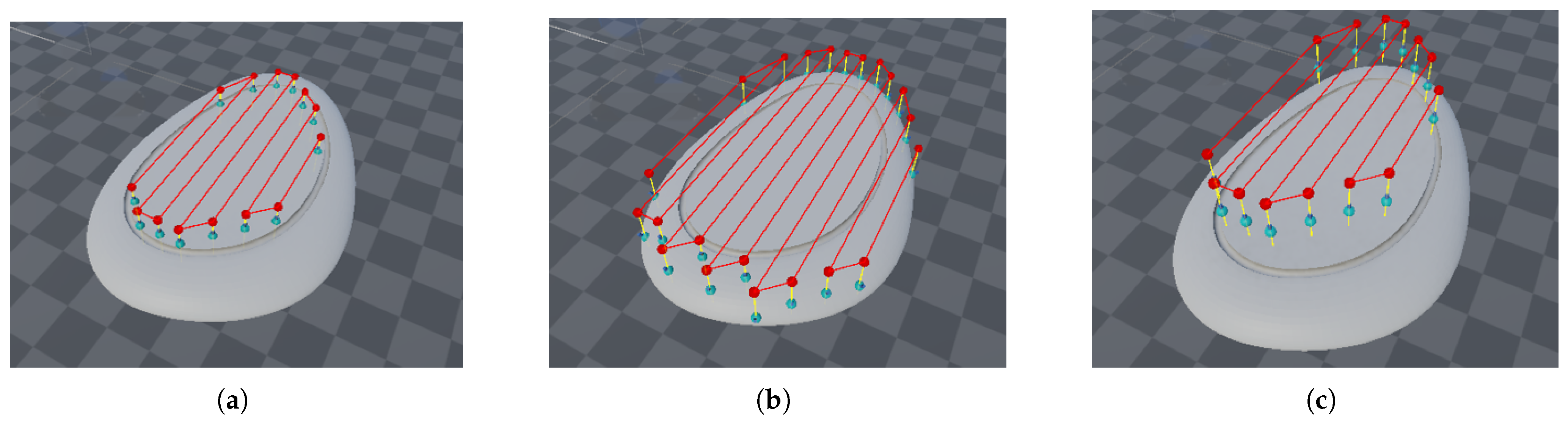
To cover entire surfaces, the R-Rain method was developed, generating zigzag point patterns by orthogonally projecting rays from a plane toward the target geometry. For this purpose, the algorithm defines a bounding box using the workpiece’s minimum and maximum dimensions, while the user specifies the spacing between trajectory points. Based on this spacing, the number of ray origins along each axis is determined as N = 2 · length / spacing and M = 2 · width / spacing , to create a grid that contains the workpiece’s dimensions. From a specified height above the part, N · M rays are projected toward the geometry, creating candidate points upon intersection. Since each grid position is evaluated independently, the algorithm presents an overall computational complexity of O ( N · M ) . The method allows for filtering curved surfaces using n · V > 0.999 , where n and V are the normal vector and V is a vector perpendicular to the plane. When curved surface filtering is enabled, an additional constant-time operation O ( 1 ) is introduced for normal vector comparison at each ray impact, allowing the classification of surfaces as curved or flat and determining whether a point is included in the final trajectory. To reduce redundancy, the algorithm only retains the initial and final points of each row, effectively registering a maximum of two points per column and reducing the final output storage complexity to O ( N ) . The objective of this R-Method is to efficiently traverse complete surfaces while minimizing redundant collinear points. Figure 8 shows the trajectories generated using the R-Rain method in three different cases, all utilizing a 25 mm row spacing.
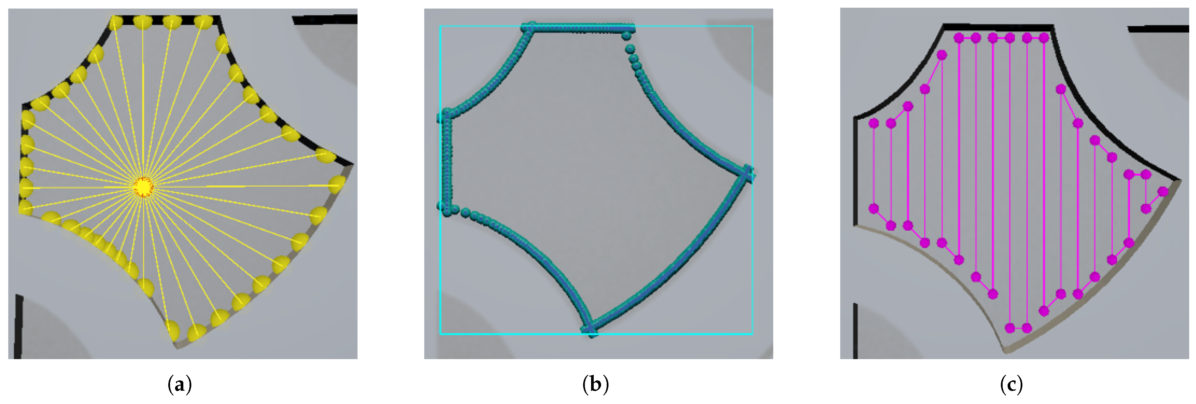
For operations on internal features, the R-Box method was developed. Based on manual selection of the internal surface of the desired cavity, R-Box generates points for both the selected area’s contour and its interior. To select the inner face of the target zone, the user must click the surface, which defines a position that emits a specified number of rays radially outward. These rays collide with the side walls that define the pocket boundary (see Figure 9a). By using the wall surface normal, points can be generated on the selected face, spaced according to the tool diameter. This process yields the contour polygon characterizing the work area, which is then incorporated into the trajectory (see Figure 9b). The contour generation stage depends on the user-defined point resolution, denoted as K, resulting in a computational complexity of O ( K ) . To proceed with pocket clearing, similarly to the R-Rain method, the minimum and maximum dimensions of the resulting polygon are used to generate a bounding box, which then creates zigzag points within the target area (see Figure 9c). The filling resolution is defined as N, which depends linearly on the target area and the pass spacing, where the step size is calculated as T = Tool size · Tool use percentage . The pocket-clearing stage therefore presents a complexity of O ( N x · ( N y K ) ) , as each generated row is evaluated against the polygon contour. Consequently, the total algorithmic complexity is expressed as O ( K + N x ) , while execution time scales linearly with the number of generated points and quadratically with reductions in T, since decreasing the step size increases the filling resolution. Regarding memory consumption, the method stores three lists of size K and one list of size N x , resulting in an overall linear memory usage complexity. To prevent collisions, auxiliary points are automatically generated between the contour polygon and the start of the clearing process. Figure 9 illustrates the three described stages of the R-Box method for generating a pocketing trajectory in milling.
To perform multiple passes to achieve the desired depth, the R-Box method has to be applied, considering virtual planes for each pass and the milling axial depth of the cut. These virtual planes act as the surface that needs to be selected by the user at the beginning of the process.
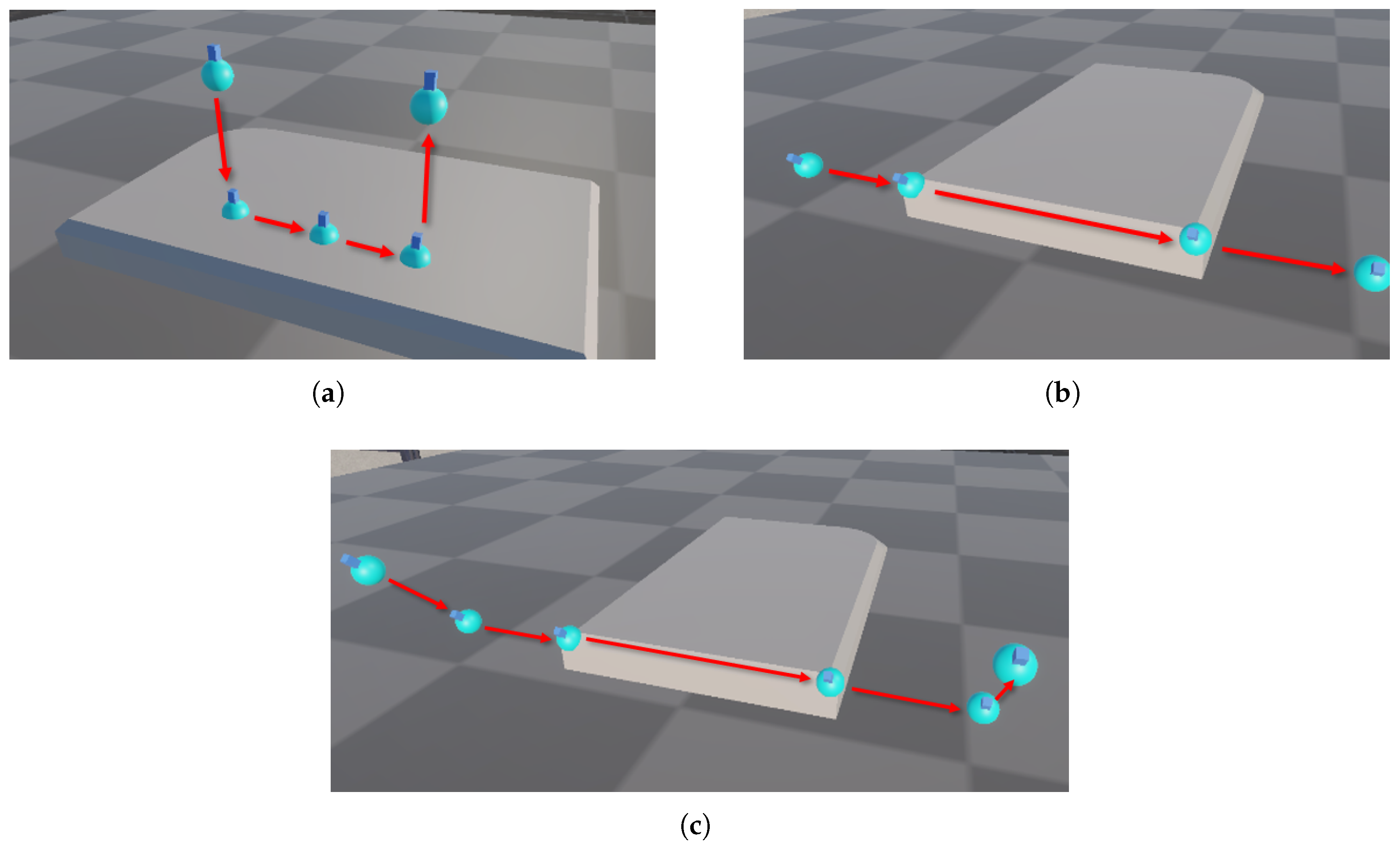
To ensure safer, more flexible trajectory generation across different manufacturing operations, transition points are integrated into the environment. Their implementation follows a hybrid approach, combining automatic and manual generation based on task requirements. For highly specific situations, users may define auxiliary points manually to maintain full control over motion behavior, which is particularly relevant in operations such as sanding, where target surfaces and contact conditions must be explicitly specified. Conversely, the implemented functions also support automatic generation of transition points, allowing seamless integration into trajectory planning workflows. For example, the R-Box method uses these functions to separate contouring and pocketing trajectories by introducing transition points that retract the tool away from the workpiece surface. Figure 10a illustrates auxiliary points that approach and retract the tool perpendicularly to the surface. Figure 10b shows the approaching and retraction points based on the robot’s trajectory direction. Finally, Figure 10c shows both types of transition points together, intended to maintain a safe clearance between the workpiece and the robot tool to prevent potential collisions and facilitate movement to the next positions.
The most significant aspect of the R-Methods is their independence from the specific type of manufacturing operation. Consequently, R-Methods can be employed in sanding, milling, painting, adhesive deposition, or any other task, making them flexible and versatile tools. Furthermore, their programming architecture enables the integration of new strategies, thereby extending the system’s capabilities without compromising compatibility with existing methods.
To evaluate the computational performance of each proposed R-Method, 30 independent execution tests were conducted for R-Click, R-Rain, R-Slice, and R-Box. Since each method is designed to generate trajectories for different features, benchmarking was performed under representative operating conditions specific to each algorithm. For R-Click, only one point was generated each time. Since R-Click uses only the ray-casting projection from the 2D screen to 3D world space, generation latency represents the minimum latency per point achievable in the environment. For R-Rain, tests were conducted on a work area of 300 mm × 300 mm with a point spacing of 10 mm, generating 88 points per execution. The R-Slice method was evaluated with trajectories composed of 100 generated points. Finally, R-Box was tested under pocketing conditions with an end-milling tool ( ϕ 3 mm) with 50% tool overlapping, yielding 426 generated points. For each experiment, generation latency was recorded and averaged over the 30 trials to reduce variability caused by system execution overhead. In addition to the absolute generation time, point generation throughput and latency per point were computed to normalize performance across methods with different output sizes. Table 1 shows the performance benchmarking.

3.3. Script Generation

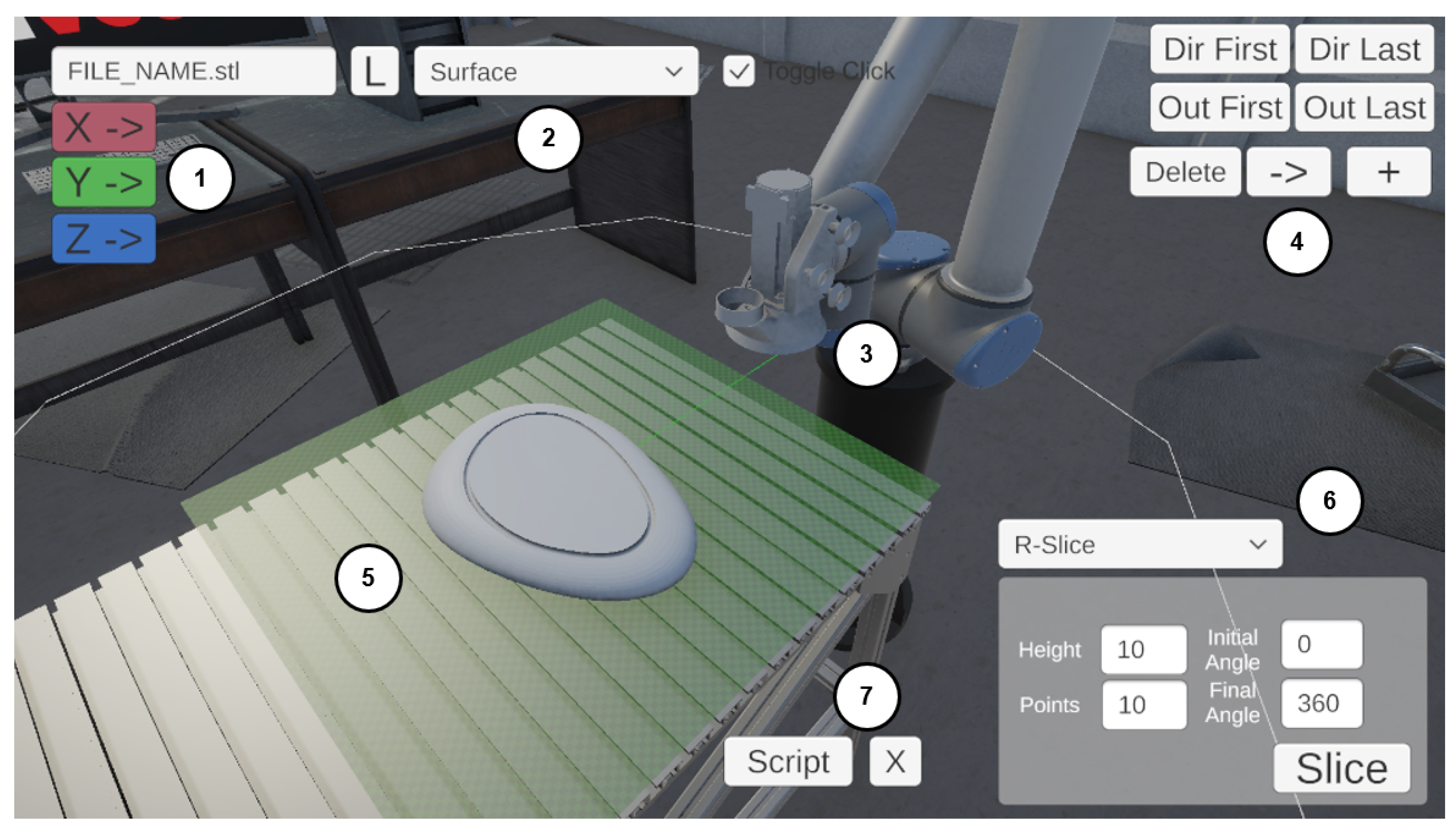
The developed OLP environment is used to generate the programming scripts. Its interface and functionalities are illustrated in Figure 11, which shows the visualization and configuration tools necessary to implement the algorithms integrated.
The developed interface integrates a set of functionalities to facilitate trajectory generation and management. It includes a text field for loading STL files, along with controls to rotate the workpiece geometry about each axis (1). Additionally, options are available to select the point type used by the various R-Methods (2) and the robot model for visualizing the generated trajectories and validating them against the actual workspace (3). The environment also incorporates functions for managing trajectory blocks and adding transition points (4) while providing simultaneous visualization of the part geometry and the points generated on its surface (5). Finally, a dedicated panel for the R-Methods is included, allowing modification of specific parameters for each method (6) and tools for the automatic generation of scripts from the obtained trajectories and the export of points to CSV format (7).
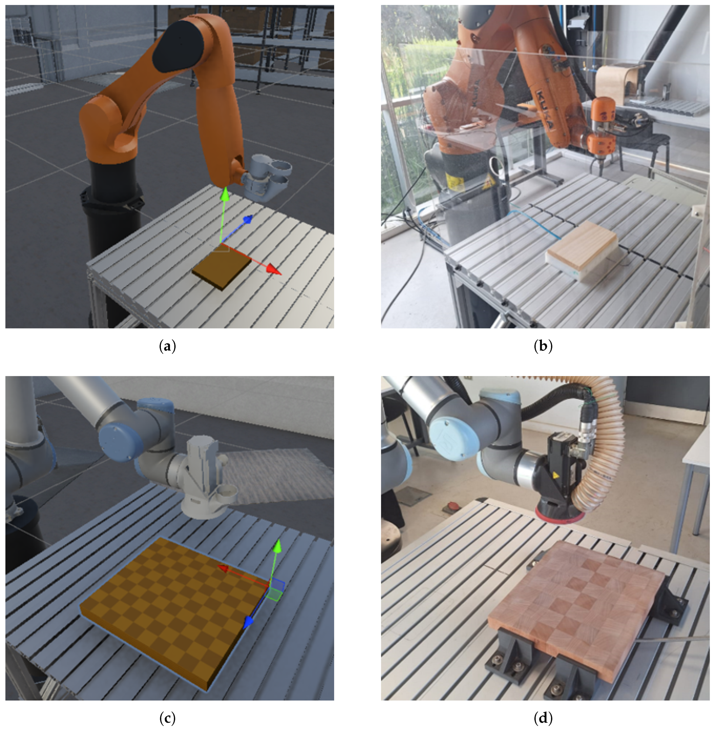
Furthermore, the environment facilitates the virtual workspace to be geometrically and spatially analogous to the physical setup, enabling validation of kinematics and robot reach and ensuring that the continuity of the generated trajectory aligns with the intended path. Figure 12 compares the virtual and real-world workspaces for both robots used in this study.
To execute the trajectories, the environment automatically generates robot programming scripts based on the points generated by the R-Methods, adapted to each robot manufacturer’s specific requirements. In this work, templates were implemented for both the KUKA Robot Language (KRL) and Universal Robots (URScript), with the generated points being integrated into a basic structure comprising positions, orientations and motion commands.
Considering the format in Equation (3), the normal vector components must be translated into angles so the robot can interpret them. Based on the normal values [ n x , n y , n z ] , the orientation angles of the end-effector are calculated for the x and y axes. To achieve this, the relationship between the point normal vector and a fixed reference vector R = [ 0 , 1 ] is used, as described in Equation (4).
α = cos 1 R · V R · V
where V = [ n y , n z ] is used for the calculation of r x , and V = [ n x , n z ] is used for the calculation of r y . Due to the radial symmetry of sanding and milling, the angle r z is kept at 0 to avoid orientation ambiguities. Depending on the robot, the component units need to be adjusted. For the UR10e robot, Cartesian units are defined in meters and radians, whereas for the KUKA robot, centimeters and degrees must be used. For the UR robot, the points must be defined in the following format:
g l o b a l P = p x , y , z , r x , r y , r z
and the trajectories are described using motion commands such as
m o v e j ( p o s e _ t r a n s ( w o r k s p a c e , t r _ p o i n t ) , a = a c c , v = v e l )
m o v e p ( p o s e _ t r a n s ( w o r k s p a c e , p o i n t ) , a = a c c , v = v e l , r = r a d i o )
For KUKA robots, the points have the following format:
P = X x , Y y , Z z , A r z , B r y , C r x
and are executed with motion commands such as
L I N P C _ D I S
P T P P C _ D I S
Ultimately, the generated scripts can be incorporated into broader task programs within the robot controller, integrating seamlessly with existing routines. In this way, the results validate the utility of the proposed environment, facilitating both trajectory generation and effective transition to execution on industrial robots from various manufacturers.

3.4. Application

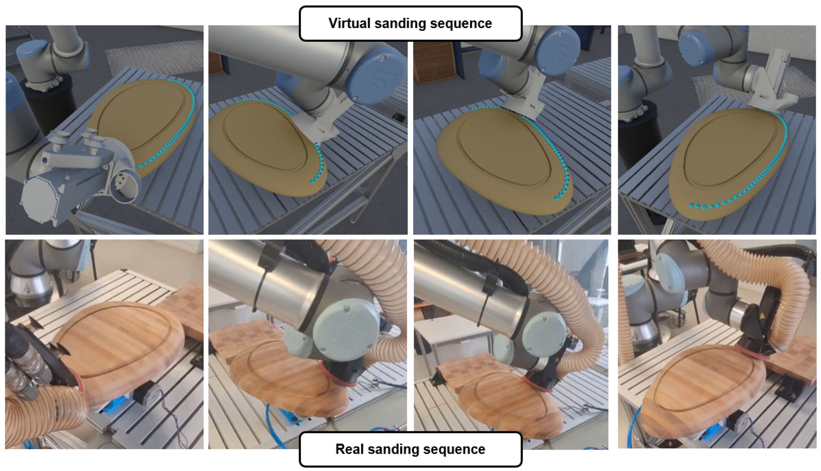
Experimental validation tests were conducted using sanding and milling stations to demonstrate the functionality of the R-Methods. In the sanding validation test, the solid wood workpiece shown in Figure 13 was used. This part features complex geometry due to its highly irregular curvature, representing a challenge for rapid programming of sanding trajectories. Therefore, to avoid singularities and maintain an optimal workspace with respect to the robot’s dynamic characteristics, the part is secured to an indexer platform equipped with vacuum tooling and a servomotor to rotate the area of interest toward the robot. The sanding trajectory for the curved surface was generated using the R-Slice method, with a base height of 25 mm, 50 points, and a 180° range. For the flat face of the piece, the R-Rain method was used using a spacing of 25 mm. For this operation, a P180 grit sandpaper was used, with a rotational speed of 2000 RPM and a feed rate of 10 mm/s. Figure 13 shows a side-by-side comparison of the trajectory generated in the virtual environment and in real-world execution.
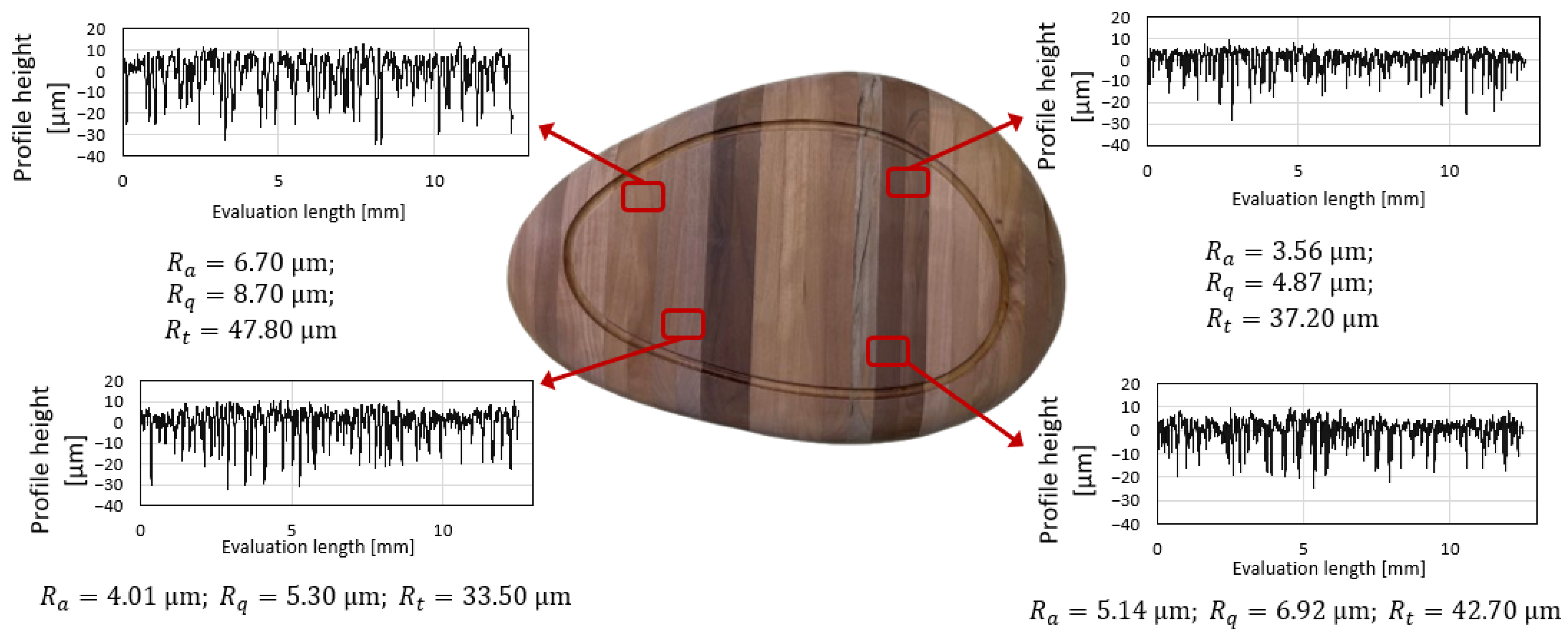
Roughness was measured in four different places of the working piece with a Mitutoyo SJ310 Surftest contact roughness tester (probe speed of 0.5 mm/s, evaluation length of 12.5 mm and using a stylus of 5 μm tip radius). Figure 14 shows roughness profiles, Ra, Rq and Rt of every test; the average Ra is 4.84 μm.
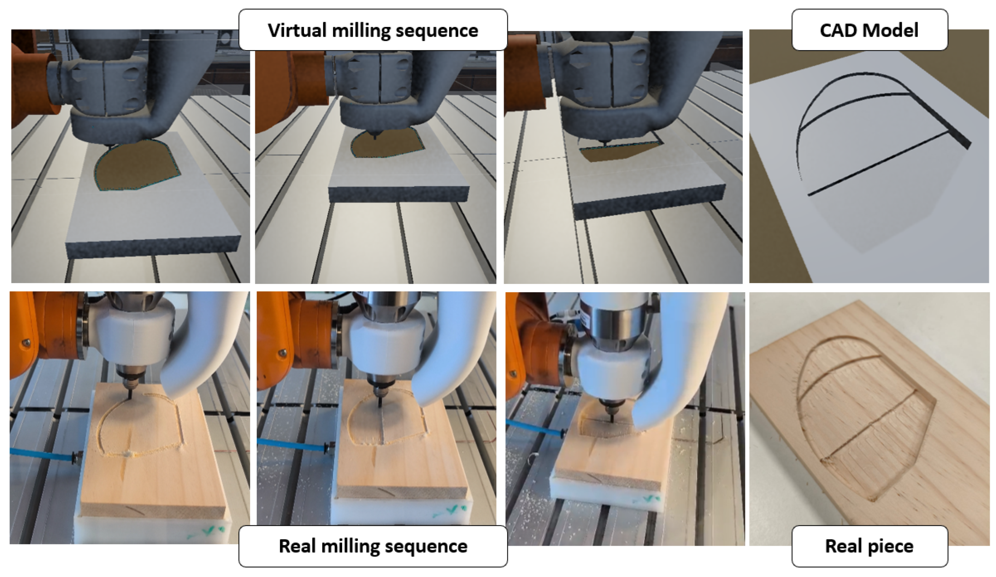
Figure 15 shows the result of a pocketing operation on a solid wood workpiece with multiple depths. For this process, the R-Box method was used six times (two passes for each height), selecting one of the flat faces of the CAD model as a reference. The operation was performed with a 4-flute, 4 mm diameter end mill, 80% overlapping, a spindle speed of 30,000 RPM and a feed rate of 10 mm/s. Additionally, auxiliary points are generated for the tool approach and retract movements in between contour and clearing patterns. The complete operation consisted of six passes of 1 mm depth.
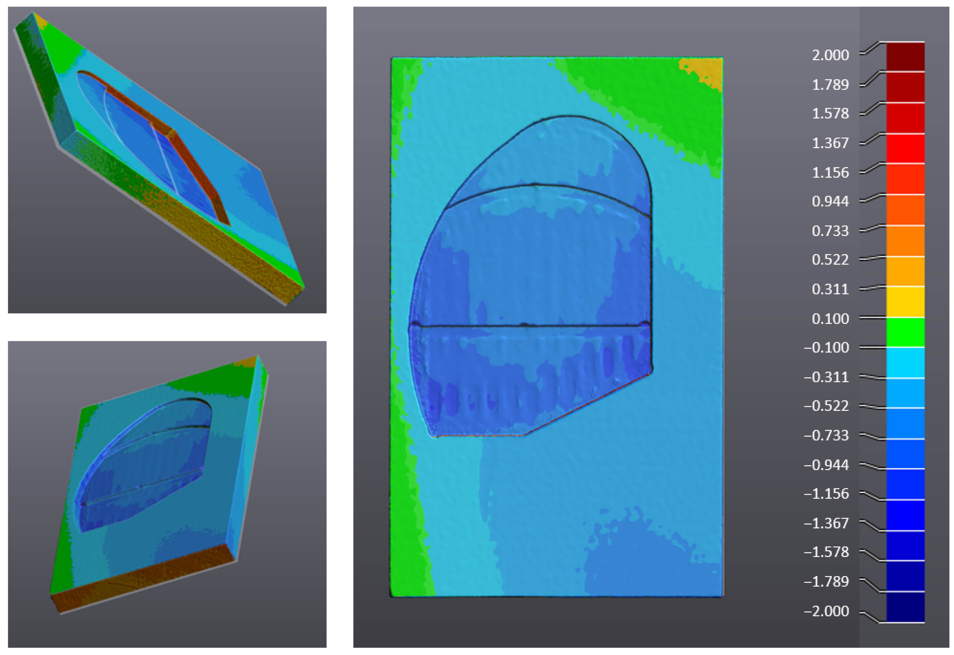
The dimensional deviations of the milled part relative to its CAD model have been analyzed. The data for the actual part was obtained via 3D scanning using a Peel 3 3D scanner with a mesh resolution of 0.25 mm. The maximum deviations obtained are 0.944 mm. Figure 16 shows dimensional deviations.
Figure 17 shows three experiments performed using the R-Box Method with different geometries and process characteristics.

4. Discussion

The literature offers a wide variety of methods for addressing trajectory generation, with direct applications in mobile robotics and path optimization under various autonomy criteria. However, the trajectories required for manufacturing operations do not share the same fundamentals as navigation-focused algorithms, such as A* [4], RRT [5], or genetic algorithms [6,7]. Due to this fundamental difference, various authors have developed specific algorithms for manufacturing operations, such as slicing [9,10,12]; trajectory generation with predefined strategies [13]; erosion methods [15]; manual edge selection [16]; or bounding volumes [17] for sanding, milling, painting and welding operations. While these algorithms provide valid solutions, they lack a common ground for feasible integration into a unified offline programming environment, limiting their applicability to highly specific, fragmented scenarios and increasing user qualification requirements. In contrast, this work presents a methodology based on a single unifying principle: ray-casting. This approach enabled the development of four “R-Methods” capable of addressing the requirements of diverse manufacturing operations under a common logic. While these methods are inspired by path generation techniques found in the literature, they offer expanded utility. For instance, R-Slice draws from the slicing approach of Li and Wang [9] and the reduced bounding volume of Bastida and Lin [17], yet it was primarily validated on elliptical components rather than large surfaces. Conversely, R-Rain focuses on covering large surfaces or irregular, flat and convex geometries, similar to the erosion methods of Shen et al. [15]. The R-Box and R-Click methods are inspired by the semi-automatic path generation and manual border selection of Bedaka and Lin [16], allowing users to specify zones where path generation is required. Unlike the specialized methods found in the literature, the R-Methods, combined with the developed OLP environment, are sufficiently generic for a wide array of manufacturing applications. Furthermore, the functional independence of these methods favors adaptability; they can be used in isolation or combined to meet specific operational requirements. This modularity facilitates applications in sanding, painting, adhesive deposition, inspection, or milling. By sharing a consistent algorithmic base, these methods coexist within the OLP environment without compatibility conflicts, streamlining the future expansion of new strategies. Based on the methodological differences of literature algorithms and R-Methods, Table 2 summarizes the main characteristics, computational requirements, manufacturing applications, versatility, and level of human intervention associated with each trajectory generation approach.
According to the offline programming steps defined by Pan et al. [2], the R-Methods in combination with the OLP environment focus on CAD visualization, spatial configuration of the workspace elements, trajectory planning, kinematic simulation and robot program generation, and process planning; dynamic aspects such as force application, tool activation and deactivation and general calibration are left to be managed within the robot base program, where the trajectories are integrated. Thus, the OLP environment and the R-Methods serve as complementary support tools for spatial trajectory planning and robot program generation.

5. Conclusions

In this work, trajectory generation methods for industrial robots were developed based on a unified operating principle using ray-casting. This approach unifies the algorithm’s logical structure and ensures compatibility within a common OLP environment.
The developed OLP environment is a practical and versatile software resource for generating tool trajectories in manufacturing operations using the proposed R-Methods, facilitating the programming and customization of movements on complex geometries without requiring intensive manual programming.
The system architecture supports the generation of scripts compatible with robots from different brands and models, thereby demonstrating the feasibility of a manufacturer-independent programming environment. Collectively, these results validate the utility and scalability of the proposed methodology, laying the groundwork for the future development of more comprehensive OLP environments capable of incorporating force control, sensing, or adaptive interaction with the environment.
Finally, the experimental results demonstrate that the generated scripts integrate easily into the base programs of the UR10e and KUKA KR6 R900 robots for sanding and milling operations, ensuring the fluid execution of trajectories. In this regard, the R-Methods and the developed environment enable a direct transition between trajectory generation and real-world execution, ultimately consolidating the practical utility of the proposed methodology.

Author Contributions

Conceptualization, E.F.-F. and E.L.-M.; methodology, E.F.-F. and E.L.-M.; software, E.F.-F.; validation, E.F.-F. and E.L.-M.; formal analysis, E.F.-F., E.L.-M. and E.D.; investigation, E.F.-F.; resources, E.L.-M. and E.D.; data curation, E.L.-M.; writing—original draft preparation, E.F.-F.; writing—review and editing, E.F.-F., E.L.-M. and E.D.; visualization, E.F.-F. and E.L.-M.; supervision, E.L.-M. and E.D.; project administration, E.D.; funding acquisition, E.D. All authors have read and agreed to the published version of the manuscript.

Funding

This work was supported by the FONDEF-Chile IT21i0069, AEI-Spain PID2021-124838OB-I00 projects and the Master of Engineering Sciences program at the Universidad de La Frontera, Chile.

Data Availability Statement

Data is contained within the article.

Acknowledgments

The authors would like to thank Pablo Sanhueza for his assistance with the experimental tasks and his valuable feedback on the functionality and capabilities of the developed methods.

Conflicts of Interest

The authors declare no conflicts of interest.

References

  1. International Federation of Robotics (IFR). The Impact of Robots on Productivity, Employment and Jobs; IFR: Frankfurt am Main, Germany, 2017; Available online: https://ifr.org/img/office/IFR_The_Impact_of_Robots_on_Employment.pdf (accessed on 4 June 2025).
  2. Pan, Z.; Polden, J.; Larkin, N.; Van Duin, S.; Norrish, J. Recent progress on programming methods for industrial robots. Robot. Comput.-Integr. Manuf. 2012, 28, 87–94. [Google Scholar] [CrossRef]
  3. Dijkstra, E.W. A note on two problems in connexion with graphs. Numer. Math. 1959, 1, 269–271. [Google Scholar] [CrossRef]
  4. Hart, P.E.; Nilsson, N.J.; Raphael, B. A Formal Basis for the Heuristic Determination of Minimum Cost Paths. IEEE Trans. Syst. Sci. Cybern. 1968, 4, 100–107. [Google Scholar] [CrossRef]
  5. LaValle, S.M. Rapidly-Exploring Random Trees: A New Tool for Path Planning; Technical Report 98-11; Department of Computer Science, Iowa State University: Ames, IA, USA, 1998. [Google Scholar]
  6. Pang, M.; Liu, Z.; Cai, S.; Ren, Z.; Zhu, Y. Variable structure GA based motion planning of a three-limbed robot. In Proceedings of the 2009 International Conference on Measuring Technology and Mechatronics Automation, Zhangjiajie, China, 11–12 April 2009; Volume 2, pp. 519–522. [Google Scholar]
  7. Ichnowski, J.; Avigal, Y.; Satish, V.; Goldberg, K. Deep learning can accelerate grasp-optimized motion planning. Sci. Robot. 2020, 5, eabd7710. [Google Scholar] [CrossRef] [PubMed]
  8. Feng, T.; Li, J.; Jiang, H.; Yang, S.X.; Wang, P.; Teng, Y.; Chen, S.; Fu, Q.; Luo, B. The optimal global path planning of mobile robot based on improved hybrid adaptive genetic algorithm in different tasks and complex road environments. IEEE Access 2024, 12, 18400–18415. [Google Scholar] [CrossRef]
  9. Li, Z.; Wang, W. Path planning for industrial robots in free-form surface polishing. In Proceedings of the 2019 5th International Conference on Control, Automation and Robotics (ICCAR), Beijing, China, 19–22 April 2019; pp. 183–187. [Google Scholar]
  10. Tsai, F.Y.; Song, K.T. Path planning and control of a 6-dof manipulator for freeform surface polishing based on a point cloud model. In Proceedings of the International Conference on Advanced Robotics and Intelligent Systems (ARIS), Taipei, Taiwan, 22–24 August 2024; Institute of Electrical and Electronics Engineers Inc.: New York, NY, USA, 2024. [Google Scholar]
  11. Wu, H.; Wang, Y.; Wei, X.; Zhu, D. Spatial path planning for robotic milling of automotive casting components based on optimal machining posture. Metals 2022, 12, 1271. [Google Scholar] [CrossRef]
  12. Chen, W.; Li, X.; Ge, H.; Wang, L.; Zhang, Y. Trajectory planning for spray painting robot based on point cloud slicing technique. Electronics 2020, 9, 908. [Google Scholar] [CrossRef]
  13. Schneyer, S.; Sachtler, A.; Eiband, T.; Notestineer, K. Segmentation and coverage planning of freeform geometries for robotic surface finishing. IEEE Robot. Autom. Lett. 2023, 8, 5267–5274. [Google Scholar] [CrossRef]
  14. Leth, N.W.; Petersen, H.G. Robot path generation for curve manufacturing processes from unstructured CAD data: An off-line programming method. In Proceedings of the ISR 2020; 52th International Symposium on Robotics, Online, 9–10 December 2020; pp. 1–8. [Google Scholar]
  15. Shen, S.; Ren, K.; Fu, M.; Yang, M.; Chen, Y. Automatic trajectory generation for metal surface droplet coloring. Int. J. Adv. Manuf. Technol. 2023, 127, 5073–5082. [Google Scholar] [CrossRef]
  16. Bedaka, A.K.; Lin, C.-Y. CAD-based offline programming platform for welding applications using 6-DOF and 2-DOF robots. In Proceedings of the 2020 International Conference on Advanced Robotics and Intelligent Systems (ARIS), Taipei, Taiwan, 19–21 August 2020; pp. 1–4. [Google Scholar] [CrossRef]
  17. Nieto Bastida, S.; Lin, C.-Y. Autonomous trajectory planning for spray painting on complex surfaces based on a point cloud model. Sensors 2023, 23, 9634. [Google Scholar] [CrossRef] [PubMed]
  18. Hughes, J.; van Dam, A.; McGuire, M.; Sklar, D.; Foley, J.; Feiner, S.; Akeley, K. Computer Graphics: Principles and Practice, 2nd ed.; Addison-Wesley: Hoboken, NJ, USA, 1996. [Google Scholar]
  19. Shirley, P.; Ashikhmin, M.; Marschner, S. Fundamentals of Computer Graphics, 3rd ed.; A K Peters: Natick, MA, USA, 2009. [Google Scholar]
  20. Renz, H.; Krämer, M.; Hoffmann, F.; Bertram, T. Next-best-trajectory planning of robot manipulators for effective observation and exploration. arXiv 2025, arXiv:2503.22588. [Google Scholar] [CrossRef]
  21. Charrow, B.; Kahn, G.; Patil, S.; Liu, S.; Goldberg, K.; Abbeel, P.; Kumar, V. Information-theoretic planning with trajectory optimization for dense 3D mapping. Robot. Sci. Syst. 2015, 11, 3–12. [Google Scholar]
  22. Pantic, M.; Meijer, I.; Girod, R.; Alatur, N.; Andersson, O.; Cadena, C.; Siegwart, R.; Ott, L. Obstacle avoidance using raycasting and Riemannian motion policies at kHz rates for MAVs. In Proceedings of the 2023 IEEE International Conference on Robotics and Automation (ICRA), London, UK, 29 May–2 June 2023; pp. 1666–1672. [Google Scholar] [CrossRef]
  23. Ali, M.A.; Maqsood, A.; Athar, U.; Khanzada, H.R. Comparative evaluation of reinforcement learning algorithms for multi-agent unmanned aerial vehicle path planning in 2D and 3D environments. Drones 2025, 9, 438. [Google Scholar] [CrossRef]
  24. Santos, J.; Oliveira, M.; Arrais, R.; Veiga, G. Autonomous scene exploration for robotics: A conditional random view-sampling and evaluation using a voxel-sorting mechanism for efficient ray casting. Sensors 2020, 20, 4331. [Google Scholar] [CrossRef] [PubMed]
  25. Bircher, A.; Kamel, M.; Alexis, K.; Oleynikova, H.; Siegwart, R. Receding horizon “next-best-view” planner for 3D exploration. In Proceedings of the 2016 IEEE International Conference on Robotics and Automation (ICRA), Stockholm, Sweden, 16–21 May 2016; pp. 1462–1468. [Google Scholar] [CrossRef]
  26. Kim, I.S.; Lee, W.K.; Hong, Y.D. Simple global path planning algorithm using a ray-casting and tracking method. J. Intell. Robot. Syst. 2018, 90, 101–111. [Google Scholar] [CrossRef]
  27. Unity Technologies. Unity for Industry. Available online: https://unity.com/es/industry (accessed on 25 December 2025).
  28. Möller, T.; Trumbore, B. Fast, minimum storage ray-triangle intersection. J. Graph. Tools 1997, 2, 21–28. [Google Scholar] [CrossRef]
Figure 1. The proposed offline programming environment with modular architecture.
Robotics 15 00132 g001
Figure 2. Generation of a point using ray-casting.
Robotics 15 00132 g002
Figure 3. Sanding and milling robotic workspaces.
Robotics 15 00132 g003
Figure 4. Measurement equipment. (a) Peel 3 3D scanner, Peel.OS 5.3 software and scanned piece with reflective adhesives. (b) Mitutoyo SJ-310 surftest contact roughness, profilometer head and unit control.
Robotics 15 00132 g004
Figure 5. Offline programming workflow.
Robotics 15 00132 g005
Figure 6. Point types: (a) Surface points located on the surface following the surface normal orientation; (b) Fixed Surface points located on the surface with a predetermined fixed orientation; and (c) Distant points located at a specified offset from the surface while following its orientation.
Robotics 15 00132 g006
Figure 7. Demonstration of the R-Slice method and its applications. (a) Visualization of ray-casting for point generation, (b) 10 points following the workpiece orientation within a 180° arc at a 50 mm offset from the surface, (c) 2 points on the surface and (d) 20 points on the surface within a 120° arc.
Robotics 15 00132 g007
Figure 8. Demonstration of the R-Rain method applied to (a) a flat face, (b) the entire surface, and (c) a flat face at a specified offset from the surface.
Robotics 15 00132 g008
Figure 9. Pocketing process using R-Box. (a) Rays emitted to detect the pocket walls on the selected face, (b) generated polygon corresponding to the contour and (c) clearing process.
Robotics 15 00132 g009
Figure 10. Auxiliary points: (a) approach points perpendicular to the surface, (b) approach points following the trajectory direction of movement, and (c) a combined configuration based on the specific application requirements.
Robotics 15 00132 g010
Figure 11. Offline programming environment layout.
Robotics 15 00132 g011
Figure 12. Comparison of virtual and real workspaces for both robots. (a) Virtual and (b) real-world workspace of the KUKA KR6 R900 robot (milling). (c) Virtual and (d) real-world workspace of the UR10e robot (sanding).
Robotics 15 00132 g012
Figure 13. Virtual and real sanding trajectory sequences.
Robotics 15 00132 g013
Figure 14. Roughness profiles, Ra, Rq, and Rt of four tests in different places of the piece.
Robotics 15 00132 g014
Figure 15. Virtual and real pocketing trajectory sequence, and comparison between the CAD model and the resulting physical part.
Robotics 15 00132 g015
Figure 16. Dimensional deviations between the milled part and the original CAD in millimeters.
Robotics 15 00132 g016
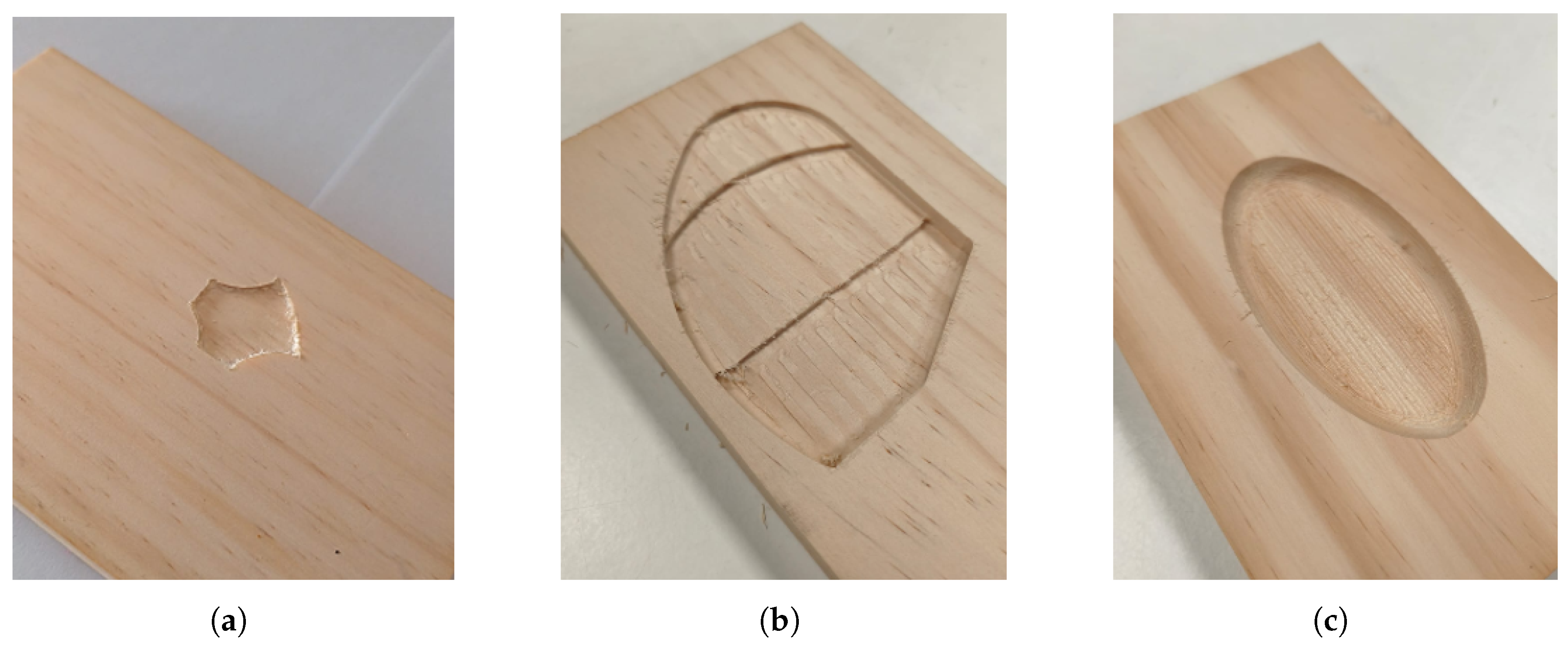
Figure 17. Examples of machined parts. (a) Contour and internal surface with 2 mm depth with a 2 mm end mill and 80% overlapping, (b) contour and clearing of multi height cavity with 2 mm cutting depth using a 4 mm end mill with 80% overlapping and (c) countour and clearing of 14 passes of 0.5 mm depth with a 3 mm ball nose end mill with 50% overlapping.
Robotics 15 00132 g017
Table 1. Performance benchmarking of the proposed R-Methods based on 30 execution trials.
MetricR-ClickR-RainR-SliceR-Box
Generation latency test [ms] 0.17 ± 0.012 8.1 ± 0.3 9.7 ± 0.5 92.2 ± 3.2
Point generation [points/ms]5.810.810.24.6
Latency per point [ms/points]0.170.0920.0970.21
Table 2. Comparison of trajectory generation methods for robotic manufacturing applications.
Performance CharacteristicGeometry Intersection-Based Methods [9,11,12,16]NURBS-Based Methods [10,13,15,17]Graph-Based Methods [14]R-Methods
Computational RequirementsRequire intensive geometric processing to solve intersection equations between triangulations or neighboring points.Require real-time tool posture optimization, surface projection over meshes, and adaptive control matrices for force or impedance regulation.Mainly concentrated in the preprocessing stage through matrix formulation for graph nodes and edges.STL loading, ray-casting, and path generation are performed with low computational cost.
Manufacturing ApplicationsSanding, polishing, deburring, painting, and welding.High-precision polishing, abrasive sanding, convex surface processing, painting, and spray coating.Machining, repair operations with edge treatments, and contouring of complex geometries.Tested on flat and curved surface sanding. Milling operations include raster, profile, and contour machining, with potential applications in painting, welding, and adhesive dispensing.
VersatilityDependent on surface characteristics, without explicitly resolving collision or singularity conditions.Algorithms automatically adapt tool orientation and spacing according to physical surface properties such as curvature.Capable of processing corrupted or unstructured CAD files.Allows point generation on any surface while considering transitions and process-specific constraints, with user-configurable parameters.
Human InterventionLow. Mainly limited to CAD model loading and process parameter configuration.Low. Mainly limited to CAD model loading and process parameter configuration.Low. Mainly limited to CAD model loading and process parameter configuration.Low. Includes CAD loading, strategy selection, and semi-automatic transition configuration.
Disclaimer/Publisher’s Note: The statements, opinions and data contained in all publications are solely those of the individual author(s) and contributor(s) and not of MDPI and/or the editor(s). MDPI and/or the editor(s) disclaim responsibility for any injury to people or property resulting from any ideas, methods, instructions or products referred to in the content.