Abstract
Path planning is a vital challenge in robot navigation. In the real world, robots operate in 3D environments with various obstacles and restrictions. An improved artificial fish swarm algorithm (AFSA) is proposed to solve 3D path planning problems in environments with obstacles. The improved AFSA incorporates a 3D model of 24 possible movement points to more realistically simulate real-world robot movement capabilities. Several improvements are adopted, such as methods of simple and advanced 3D elimination. The 3D implementation of an agent’s navigation model, called an “obstacle heatmap”, is also presented. The use of a safety value factor and a total movement point factor in the AFSA’s objective function are introduced. The combination of improved AFSA and a ray-casting algorithm is also presented. Finally, a method called “multiple laser activation” is introduced to overcome both the main disadvantage of the application of AFSAs in path planning and the limitation of the finite number of possible movement points that appear when bio-inspired algorithms are applied to generate the optimal path in a grid environment. The resulting path is applied to real-world challenges with drones, coordinate measuring machines, and industrial robotic arms.
1. Introduction
Drones are becoming increasingly popular in several application areas, such as education [1], topography [2], inspection tasks [3], rescue operations [4], and military applications [5]. The multirotor is the most common type of drone; it employes multiple rotors that enable it to fly. A vital challenge for successful drone operations is path planning. The purpose of path planning algorithms is to find a sequence of points that lead from a starting to an ending position while avoiding obstacles in the drone’s flight environment. The importance of path planning is relevant to several areas, such as road network development policy in cities [6], unmanned aerial vehicles (UAVs) [7], the problem of the optimization of delivery vehicle routing [8], mobile robot navigation in environments with obstacles [9], automated guided vehicles (AGVs) [10], and dynamic building fire rescue operations [11]. The path planning process is executed separately from the drone’s control loop and is conducted online or offline, depending on whether the environment and obstacles are known in advance or not. The process of solving the path planning problem consists of two major steps: modeling the real environment to a virtual environment and searching for the optimal path [12].
Drones can easily navigate in three directions in outdoor environments and adjust their orientation by modifying the three Euler angles. In addition, spatial obstacles, such as trees and human-made structures, are encountered during outdoor drone navigation. In this paper, for effective drone path planning and detailed simulation of the physical environment, the problem of finding the optimal path is solved by adopting a 3D environment approach. The use of a 2D environment would be equally effective in cases where the drone navigates at a constant altitude. The proposed methodology for finding the optimal path in a 3D environment can also solve these cases by appropriately modifying the input data. Finding the 2D path is a sub-case of the 3D path finding process.
One of the main issues preventing the widespread use of drones is their limited flight time due to battery depletion. Li et al. mentioned that energy consumption can be reduced by decreasing the number of turns in a flight path [13]. For a given fixed distance, a drone’s flight time increases when the path contains turns instead of straight lines. The flight time increases because the drone has to stop completely in order to change the yaw angle and continue its course while maintaining a constant aircraft orientation. Furthermore, to stop and change its orientation and direction, the drone needs to slow down and then speed up. Unlike ground vehicles, drones do not use a mechanical brake system to slow down; rather, a drone’s speed is controlled by increasing or decreasing the rotational speed of its propellers and by its aerodynamic drag. Multirotor drones are able to move in any 3D direction. Thus, they can change direction without changing the heading orientation. However, during the path planning process, it is important to avoid zig-zag movements and keep the course as straight as possible in order to reduce the time and energy spent on every turn.
Alongside drones, similar challenges in the path planning process are also encountered by other robotic systems with identical motion capabilities but different sizes or mechanical parts, such as industrial robots and coordinate measuring machines (CMMs). The main challenge is to develop an autonomous path planning procedure that allows robots to operate independently of any external human interaction and aligns with the mobility of the robotic system. CMMs and industrial robotic arms can navigate in 3D space and also change the orientation of their end effector. It is noteworthy that criteria such as the speed of task execution, obstacle avoidance, and energy saving are common to drones.
The path planning problem, due to its multiple applications and importance, has attracted the interest of several researchers. Ning et al. proposed an improved mutation operator genetic algorithm in a 3D environment to improve the accuracy and efficiency of a sediment sampling process in oceans [14]. Wang et al. proposed an improved rapidly exploring random tree (RRT) algorithm for welding industrial robotic arm path planning [15]. Sathiya et al. proposed a fuzzy enhanced improved multi-objective particle swarm algorithm to solve path planning problems faced by ground vehicles [16]. Liang et al. suggested an efficient artificial bee colony algorithm to solve the online path planning of multiple mobile robots while avoiding obstacles and other robots in an experimental environment [17]. Xie et al. used an improved ant colony optimization algorithm to solve the multi-objective inspection path planning problem in radioactive environments so that professionals working in these environments receive the lowest possible radiation dose during the overhauling of nuclear power plants [18]. Chen et al. introduced a framework of trajectory planning for UAVs with two parallel planners. The map planner finds the shortest path in limited computational time using an improved jump point search (JPS) method; then, the point cloud planner is activated when the point cloud near the drone differs from the 3D map to avoid any potential collision [19]. Liu et al. presented a multi-objective optimization model for bus route optimization using a pareto artificial fish swarm algorithm combined with a crossover and mutation operators [20].
The Artificial Fish Swarm Algorithm (AFSA) is a type of swarm intelligence optimization algorithm that belongs to the continuous solution domain optimization category [21]. Zhang et al. proposed a hybrid algorithm combining the A* and an improved artificial fish swarm algorithm to solve the 2D path planning problem [22]. Li et al. applied a combination of artificial fish swarm algorithms and the artificial bee colony swarm algorithm [23]. Fang et al. combined a real coded genetic algorithm (RCGA) and AFSA for the short-term hydrothermal scheduling of a complicated nonlinear optimization problem with a series of hydraulic and electric system constraints [24]. Peng et al. proposed artificial fish swarm optimization to improve foraging behavior in order to enable the artificial fish to perceive more information about their surroundings, to obtain an optimal state, and to select the most beneficial movement direction [25]. Qi et al. used an AFSA to optimize the battery capacity, charging current, and discharge current of a three-lithium battery-powered system to extend its lifetime [26].
During the evolution of research in this field, several researchers have proposed new modifications and variations of traditional AFSA. Multi-objective optimization problems (MOOP) have more than one objective function to satisfy. Traditional AFSA was designed to execute global optimization in single-objective optimization problems. Thus, to solve MOOP, several researchers have adjusted the algorithm to satisfy the requirements of these problems. Xu et al. nominated an iterative deletion artificial fish swarm algorithm that integrates the global optimal solution into the AFSA’s behaviors in order to find the appropriate parameters for suspension and a mechanical elastic wheel [27]. AFSA has also been used to solve optimization problems in dynamic environments. In this kind of problem, the search space modifies over time because of the changes in constraints or the objective function [28]. Yazdani et al. suggested an AFSA for optimization in dynamic environments in which changes in the problem space occur in discrete intervals. Their method categorizes swarms into three main types and configures them in a way that they can demonstrate high efficiency in terms of performing their assigned tasks [29]. Many researchers have proposed hybrid AFSA models to leverage their strengths and counter their imperfections. Yaseen et al. combined the follow and the swarm behavior of AFSA with particle swarm optimization (PSO) to optimize a dam reservoir, increase energy production, and minimize downstream water shortages [30]. Zhang et al. used AFSA’s crowding factor to prevent an artificial bee colony from falling into local optimal solutions [31]. Zheng et al. integrated the AFSA’s follow and swarm behavior with the bacterial foraging algorithm in order to overcome the poor convergence speed and the local optima drop of the bacteria foraging algorithm [32]. Fang et al. applied a combination of AFSA and PSO to detect the onset of ultrasonic signals [33]. Guo et al. proposed a hybrid model combing AFSA with an ant colony algorithm-based backpropagation neural network to compensate for the thermal error during a precision machining process using a computer numerical control (CNC) machine [34]. Zhuang et al. combined a multi-strategy artificial fish swarm algorithm with support vector regression to determine the mechanical parameters of surrounding rock masses in tunnel engineering [35]. Zhou et al. suggested a chaotic parallel artificial fish swarm algorithm to optimize water quality monitoring sensor networks [36].
Path planning in 3D environments needs to overcome several challenges in order to be successful. The existence of static obstacles increases the complexity and demands of the path planning process. Important factors are the density of obstacles and their positions in the environment. Finally, a path planning process needs to take into consideration obstacle avoidance, flight time minimization, and the robot’s movement capabilities, which can sometimes conflict.
Collision detection and path planning strategies need to be implemented in order to generate optimal motion paths for automatic navigation in a 3D environment [37]. Path planning can be achieved using two different types of methodologies. Offline path planning finds and optimizes the trajectory before a drone’s flight. On the other hand, online path planning generates trajectories during flight. Tan et al. combined the Nash equilibrium algorithm with particle swarm optimization to solve the UAV path planning problem in complex 3D environments with obstacles [38]. Zhang et al. proposed a collision free path planning algorithm that takes into account the static obstacles and dynamic threats that are typical of urban airspace environment operations [39]. Colas et al. suggested a real-time point cloud-based system and lazy tensor voting to navigate in a 3D environment [40]. Wang et al. proposed a framework based on deep learning path planning and tracking control for obstacle avoidance and real time navigation of a fixed-wing UAV in a 3D environment with obstacles [41].
In robotics, the accurate simulation of a real environment through a digital model is vital. The evaluation of the quality of the formed digital paths is directly related to the accuracy of the 3D model and the requirements of the performed task due to the fact that the formed path will be executed in real-world conditions. Although the accurate digitization of the real world is an open research field, there have been several proposals for the implementation of path planning algorithms using different 3D modeling methodologies [42,43,44]. An effective and popular 3D modeling method is the grid environment methodology [45,46]. The grid method simulates a real-world environment using a set of feasible discrete points for the areas in which robots can move freely and infeasible discrete points to simulate obstacles or restricted areas.
Comparatively, with other swarm intelligence algorithms like particle swarm optimization or ant colony optimization, AFSA does not keep any previous information about the quality of the selected positions in a memory structure. As a result, a path that consists of several points and approaches a high percentage but is not completely the optimal path is not optimized further during the algorithm’s execution in order to completely examine its potential to become the optimal path; rather, it is completely discarded if a shorter path is created. This trait can be a disadvantage in the path planning problem, especially in cases where a route with a large number of intermediate points needs to be formed. On the other hand, it significantly reduces the required execution time for path formation.
Researchers have made significant efforts to expand the scope of application of the AFSA and optimize its performance and the quality of the provided solutions. However, the lack of some form of memory is regarded as a disadvantage that arises from the algorithm’s structure, and no solution has yet been proposed to deal with it. Moreover, researchers have successfully implemented several algorithmic methods to solve the path planning problem in a 3D grid environment with obstacles. Nevertheless, due to the large number of the next possible movement points and the increased complexity of the 3D environment, restricted 3D applications of the 4 or 8 possible movement point models for agent navigation have been adopted. On the one hand, the implementation of these navigation models leads to optimal solutions successfully, but on the other, the length of the formed paths can be reduced even further by using a model with 24 possible movement points [47]. Another challenge faced by path formation algorithms is that increasing the accuracy of a natural environment’s representation prolongs their execution duration. As a result, the significance of algorithms with a fast convergence rate in such conditions is further emphasized.
This paper presents solutions to the problems described above. The AFSA is used with a 3D model of 24 possible movement points model in a dense grid environment that can accurately represent the real-world environment in which the robots are operating. A technique for solving the AFSA’s lack of a memory structure in the path planning problem is presented.
In this paper, the incorporation of an improved AFSA with a ray casting algorithm is proposed in order to solve the offline path planning problem in a 3D environment with obstacles. The improved AFSA proposed in [47] is implemented in 3D path planning and further enhanced. An appropriate enhancement of AFSA is presented and applied on a modified navigation model of 24 possible movement points in order to more thoroughly explore the attainable alternative paths and to more realistically simulate the motion capabilities of robotics systems. Moreover, the next movement point selection process is improved by a simple and advanced 3D point elimination procedure. In this procedure, the points whose selection significantly excludes the optimal path are deleted from the set of possible movement points, and the agent is limited to choosing points that can lead it effectively to the end point. An advancement of the obstacles heatmap presented in [47] is also introduced to improve the agent’s navigation in a 3D environment, and the effectiveness of the heatmap in 3D dimensions is examined. The use of the safety value factor and the total movement point factor in the objective function is proposed to optimize the fish navigation in a 3D environment and to find the shortest 3D path that successfully connects a start to an end point in dense environments. Finally, a multiple laser activation method is proposed to mitigate the main disadvantage of AFSA, i.e., the lack of a memory structure, in the path planning problem. The multiple laser activation method also further optimizes the optimal path and overcomes the limitation of the finite number of possible movement points encountered when applying bio-inspired algorithms in a grid environment to solve the path planning problem. A comparison of the results of the proposed algorithm with those of some state of the art path planning algorithms is presented. The introduced methodologies and algorithms were subjected to a variety of 3D environments with obstacles. They performed successfully on real-world tasks, such as quadcopter drone navigation in urban ecosystems, object transportation using a 6-degree-of-freedom industrial robotic arm, and performing measurements using a CMM in an environment with multiple components.
The main contribution of the presented methodologies compared to other state of the art path planning algorithms can be summarized as follows:
- An enhanced AFSA that implements a 3D model of 24 possible movement points to solve the path planning problem;
- The application of an obstacle heatmap navigation model to a 3D environment with obstacles;
- A multiple laser activation methodology that can provide a solution to the AFSA’s problem, i.e., the lack of a memory structure in path planning, enables AFSA and other bio-inspired algorithms that address the problem of finding the optimal path in a grid environment to select the next possible movement point beyond the models of 4, 8, or 24 possible movement points and reduce the number of points in the optimal path.
2. Materials and Methods
2.1. 3D Grid Creation
The simulation of a real-world drone flight environment was accomplished using the 3D grid environment method. A 3D grid environment consists of many suitably organized elementary finite rectangular parallelepipeds, as shown in Figure 1a,b. Then, at the center of gravity of each elementary parallelepiped, a discrete point is placed that represents the space occupied by the volume of the elementary parallelepiped. The drone’s center of gravity can be moved on the coordinates of the discrete points and the planned path is derived based on this reference point.
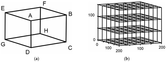
Figure 1.
Virtual representation of 3D environment: (a) Finite rectangular parallelepiped; (b) 3D environment of rectangular parallelepipeds.
2.2. Obstacles
In many cases, it is necessary to limit the movements of a drone to some discrete points because in the real world, there are obstacles and it is impossible for a drone to move to those coordinates without causing some damage to the obstacles in the environment or to its mechanical or electronic parts. The set of coordinates can be visible physical obstacles, such as the buildings shown in Figure 2, or invisible, e.g., the airspace of airports. The presence or absence of an obstacle for each discrete point is defined with the numbers 0 and 1, respectively. Due to the fact that the discrete point of each obstacle represents a spatial set of coordinates, for each point separately, all the planes of each elementary parallelepiped are recorded so that the robot is not allowed to enter that region.
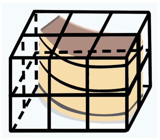
Figure 2.
Real-world building structure representation of a grid environment as an obstacle.
2.3. Robot’s Movement
Simulating the robot’s real-world motion capabilities in an artificial 3D environment is crucial for the reliability and validity of an algorithm’s results. Drones can move easily and quickly in all directions without being limited by mechanical or kinematic restrictions, in contrast to ground vehicles or fixed wing UAVs. In current research, an 8 possible movement point is used for the selection of the next point from a definite position in a grid environment. Although this model allows optimal path-finding algorithms to choose the next possible point from a small number of possible available choices, it allows the robot to move in only 8 directions. In this paper, a 24 possible point model with 16 different possible directions is used to more precisely simulate a real-world drone’s movement capabilities. In addition to the 24 near possible movement points located in the 2D plane, all the points with the same X and Y coordinates as the 24 and the current drone position along the Z-axis are considered as possible movement points. This is because drones can move flexibly in 3D space, resulting in an increase in possible movement points and directions. Figure 3 shows an example of the considered possible movement point space from a specific location. The agent’s location is shown in green, the yellow arrows indicate the points the agent can move to when an 8 possible navigation model is used, and the black arrows indicate the additional alternative possible points that a 24 possible navigation model is applied.
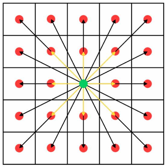
Figure 3.
8 and 24 possible navigation points model.
Using the record of the obstacle’s planes, as mentioned in Section 2.2, for each point that is enclosed within the robot’s area of motion, it is checked whether the line connecting the robot’s current point to the destination point intersects any of the planes of the elementary rectangular parallelepiped of an obstacle. Thus, if an intersection point is detected, the robot is not allowed to move toward that destination point because, in the real world, there would be a collision with that obstacle.
Considering points P(x1,y1,z1) and Q(x2,y2,z2), vector PQ<x2−x1, y2−y1, z2−z1> is obtained. Knowing all the plane equations, i.e., , for each elementary rectangular parallelepiped and the exact points that delimit the area of the obstacle, the point of intersection of the line and the plane is located. If the intersection point is inside an obstacle area, then a collision is detected. Then, by substituting x, y, and z from from Equations (1)–(3) in the equation of the plane, we can calculate h. The coordinates of the intersection point [x, y, z] are obtained by substituting h in Equations (1)–(3).
2.4. 3D Artificial Fish Swarm Algorithm
The Artificial Fish Swarm Algorithm is employed to determine the optimal route in a 3D grid environment. AFSA reproduces four natural fish behaviors: preying, swarming, following, and random.
Prey behavior is a weighty behavior in the AFSA. In preying behavior, the fish selects the next possible position in its vision field randomly. The fish performs the selection according to Equation (4):
After point selection, in order to move the fish to its next position, a comparison between the objective function’s values of the two positions is conducted. Variables Yi and Yj represent the objective function values of the present and next possible positions, respectively. If the case where Yj > Yi is encountered, the fish moves from its current location one step toward the selected location, according to Equation (5). Otherwise, the procedure of Equation (4) will be replicated until one of the following criteria is satisfied. A position will be found where Yj > Yi or the process repetition number is greater than an allowed value of the parameter fishTryNum. Random behavior is executed if a position with a higher value cannot be found. In this way, the navigation criteria set in the objective function can be used in the searching process of the next possible movement point. The term ||Xj−Xi||, appearing in Equation (5), represents distance dij between locations i and j of the fish.
Swarm behavior is used by the artificial fish to assess the quality of the solutions within its visual area. The quality of the solutions is determined by the distribution of fish within the search area around their present location. Swarm behavior is performed according to Equations (6)–(8).
The center position is calculated by taking into consideration the selections of the other fish. The center position can be selected if both of the following situations are met. The first situation requires YC > Yi and the second considers the possibility that the fish may have huddled at a center location. YC is the value of the objective function at the center position. The density of fish at a location is examined through the crowded degree δ ∈ (0,1). Equation (6) is used to calculate the center position; variable nf represents the number of fish in the field of view. Equation (7) calculates the crowded degree; N represents the total number of fish. The artificial fish will move a step toward the center position, according to Equation (8), if the described situations are met. Otherwise, prey behavior will be executed.
The following behavior is used by the artificial fish to take into account the previous selection in its visual area, according to Equation (9).
There are two requirements that must be satisfied in order to perform the following behavior: The first examines objective function YF of the optimal position; the second is the number of fish that have already been located on it. When YF > Yi and the crowded factor indicates that there are not many fish in this location, the artificial fish moves closer to the optimal location. Otherwise, prey behavior is executed.
In random behavior, the artificial fish randomly moves within its visual field. This type of movement allows the fish to avoid local optimal solutions and explore more possible optimal paths. Equation (10) describes the random movement of the fish.
Random behavior is performed according to Equation (10). In this behavior, the random factor is used in the movement of the fish. The random movement of fish contributes to the wide exploration of the map and the avoidance of local optimal solutions. This behavior also takes place within the view range of the fish.
In our study, instead of random behavior, the behavior proposed in [47] is used. In the new behavior, when the number of attempts for the selection of the next point surpasses the value of the parameter fishTryNum, preying behavior is executed differently. Rather than performing random behavior, the next movement point is chosen from among the points that have already been inspected. The point whose location presents the highest value of the objective function is selected.
Figure 4 visualizes the artificial fish positions and AFSA’s process; green shows the point where the swarm of the fish is located in position Xi (i = 1, 2, 3…N) and red represents possible next location Xj.
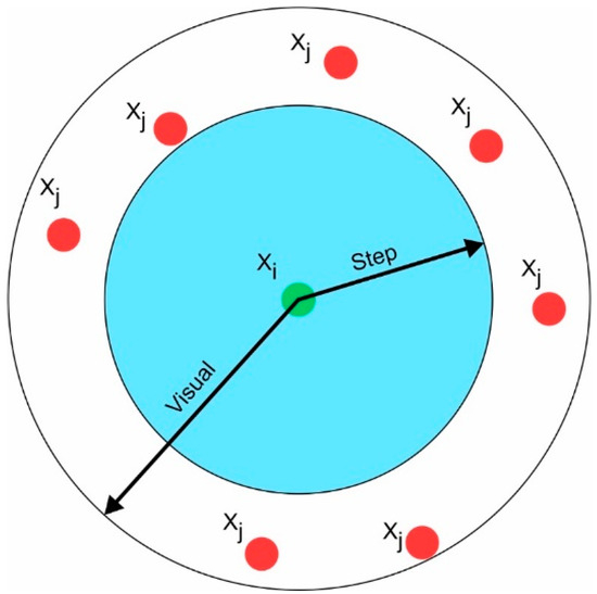
Figure 4.
AFSA searching for the next position in a local environment.
2.5. Improved 3D Artificial Fish Swarm Algorithm
The proposed application of the 24 possible points model to a 3D environment creates multiple possible options for the artificial fish of different step sizes and field of view ranges. These parameters can significantly affect the response and efficiency of the AFSA. Their incorrect tuning can cause unnecessary oscillations and delay the algorithm’s convergence speed. The various values in the step variable and the divergent movement direction options can benefit the exploration of the environment without dramatically altering the algorithm’s convergence speed or increasing the number of iterations. Nevertheless, especially in a 3D environment, the number of possible next movement points is considered relatively sizable. Thus, finding the ideal path without a memory structure or post-processing in a dense environment is challenging. In order to overcome this challenge and successfully apply the AFSA with the 24 possible movement points in a 3D environment, the elimination of unnecessary 3D points is proposed. Several possible movement points can lead the fish to a more unfavorable position than where it is currently located. Thus, these points are detected and eliminated from the set of possible movement points, so that the fish may still have several possible options, but any one of them will lead it closer to the ending point. This process is conducted in two stages: simple and advanced 3D elimination.
Simple 3D elimination examines all possible points and calculates their distance from the ending point, according to Equation (11). Then, the distance of the point where the fish is located from the ending point is calculated and it is compared with the calculated distances of all the possible movement points. If variable delim of the next possible movement point is shorter than the current location, it is eliminated. Index j denotes the next possible examined movement point, e is the ending point location, and i represents the position of the fish.
The second stage is the advanced elimination of the points. In the advanced elimination, every remaining point from the process of simple elimination is further examined. This procedure is carried out by executing simple elimination as if the fish had been transported to the point in question. In addition, for the examined point, all points in common with the point where the fish is located are eliminated. If the advanced elimination eliminates all possible points, it indicates that the selection of this point is unbeneficial. Then, the examined point is eliminated from the set of possible movement points. Such points are those located before dead ends, near obstacles, or with limited movement possibilities. Advanced elimination assists the fish in determining if moving to a point on its next move will help it get into a better position than its current location. Figure 5 shows the elimination process for a point in a 3D plane; green indicates the point where the fish is positioned, blue shows points that have been eliminated, orange shows the points that remain, black shows obstacles, and purple shows the ending point. While initially there were 71 possible movement points, after the elimination process, 27 remained. The dashed line represents the distance between the fish’s current location and the ending point.
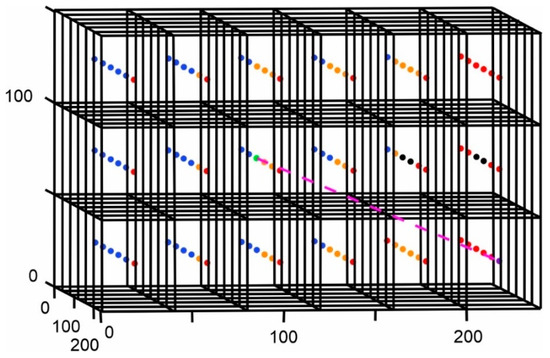
Figure 5.
3D point elimination.
The obstacle heatmap proposed in [47] has been extended and applied in a 3D environment to increase the navigation performance of the fish. The information interchange between the availability of the positions in the environment and the artificial fish benefits the selection of the next movement point among the larger number of possible points in the set. The following parameters are used to create the map:
- The heat value of the obstacle—obsHeatVal;
- The coefficient of increasing the heat across the map—heatIncrCoef;
- The heat value of the points in the first heat map values update—obsNearHeatVal;
- The heat value of the points in the second heat map values update—obsNearHeatVal2.
During the creation of the map, a numerical value is assigned to each discrete point. The first step is to determine an initial obsHeatVal for each obstacle point inside the grid. Then, each obstacle point is considered as a distinct movement point in which the fish is located. For each of the possible movement points, a value is assigned, according to Equation (12), where index i represents the point where the fish is positioned, j the next possible movement point, and a is the side length of the elementary finite rectangular parallelepiped. In the denominator of Equation (18), the length of the distance between the points where the fish is located and the furthest point from it remains the same as in [47] in order to emphasize the differences between points that are at the same plane as the obstacle and those that are at a different point.
Equation (13) is used to repeat the procedure for all points whose value on the map has been changed and are not obstacles. In this stage, the discrete point values are smoothed, the obstacle regions are highlighted, and the points leading near the obstacles are numerically represented.
Equation (14) is used for the final stage of the heatmap generation in which the number of the set of possible points for all discrete points t is determined without considering obstacles. In Equation (14), np represents the number of the next possible points when the fish is placed on the examined point and m represents the maximum number of movement points that a set of possible points can contain. This separates the areas that are located in the corners or edges of the environment from which the robot has fewer movement options compared to the center area.
Comparing the heatmap value between the possible points of movement that arise from a given position with the average value resulting from all points on the heatmap assists fish navigation. There are four separate comparison areas. Each area defines the distribution of some penalty or bonus to the value of the objective function of the points that are located at a predetermined distance from the given position of the fish. The bonuses and the penalties decrease or increase the value of the objective function of the points by a certain rate, making them less or more appealing choices for the fish. Thus, various policies can be created that encourage or discourage movement to certain points, depending on the environment.
Randomly activating the map for the 2D path planning case showed a significant improvement in the final results. In this paper, we also tested the efficacy of randomly activating or deactivating the heatmap to enhance navigation in a 3D environment.
The complexity of the 3D environment, the large number of possible movement points, and the presence of obstacles increase the difficulty of finding the optimal path. In order to deal with these challenges and improve the robot’s navigation process in this paper, the safety value factor and the total movement point factor are introduced. The safety value factor assists artificial fish in avoiding obstacles, and the total movement point factor helps during the next possible point selection process. The safety value factor is calculated according to Equation (15), where k represents the total number of discrete points from the position where the fish is located and g the total number of obstacles from the same location. The total movement point factor is calculated according to Equation (15), where w represents the number of discrete points eliminated due to the existence of obstacles during the process of generating the set of possible motion points for the point where the fish is located.
The objective function is particularly important for the convergence of the algorithm and in finding the optimal path. It determines the artificial fish’s movement and evaluates each possible movement point to successfully reach to the ending point. The objective function used is described in Equation (17), where indexes I represent the current location of the fish, ending at the end point location. Coefficients w1 and w2 represent the importance of the safety value factor and the total movement point factor, respectively.
The integration of a ray casting algorithm with the artificial fish swarm algorithm applied in a 3D environment is proposed in this paper. An artificial laser beam ray is attached to the artificial fish. The artificial laser aims from the location of the fish to the end point. If the laser is not intercepted by an intermediate obstacle, the next point selected by the fish is the ending and the formed path is completed. If the ray encounters a 3D obstacle, the artificial fish swarm algorithm is executed, as described in the previous sections, to find the next movement point; this process is repeated until the fish reaches the ending point. The laser method is performed as described in the section on drone movement using Equation (1)–(3). Figure 6 shows an example of a laser procedure. The fish located on the green point casts a blue laser beam to the end point in purple, but it segments the plane of the obstacle.
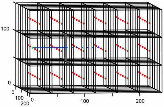
Figure 6.
Laser beam casting obstructed by an obstacle.
A disadvantage of AFSA when applied to solving the path planning problem in a complex dense environment is the lack of a memory structure. A solution is proposed through the multiple activation of the laser method. When a laser is activated as described in the previous section, the point where it was activated is recorded in a separate vector. After the completion of the algorithm, the search for the best path is repeated with the supposition that the fish are looking for the shortest path from the starting point to the set of points where the laser has been activated, instead of the end point. In the formation of the total path for each formed route, the end point is added after the point where the laser was triggered. The length of the paths formed is calculated; for the one with the shortest length, the same procedure is repeated with the difference that instead of adding the end point after the final point of the path, before the ending point, the point where the laser was activated and recorded is added. The process is repeated until the point where the artificial laser will be triggered becomes the starting point. In this way, a complex route is separated into smaller routes, and its final optimized points are kept in a memory structure. Figure 7 shows a 2D simplified example of the above procedure. In blue are the points where the laser was activated. The formed path is shown in magenta.
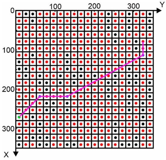
Figure 7.
Multiple laser activation 2D example.
The distance between the movement points is calculated according to Equation (18).
The total path’s length is calculated according to Equation (19).
The improved AFSA uses the following parameters:
- The number of maximum iterations—MaxIt;
- The maximum number of steps until a complete path is formed—MaxStepsNum;
- The population size of the fish swarm—numFish;
- The fish swarm’s number of attempts to find the optimal location—fishTryNum;
- Crowding factor—δ;
- The number of maximum laser iterations—LMaxIt—for the multiple laser activation method.
2.6. Flow Chart
Figure 8 shows a flow chart of enhanced AFSA combined with the ray casting algorithm in a 3D environment.
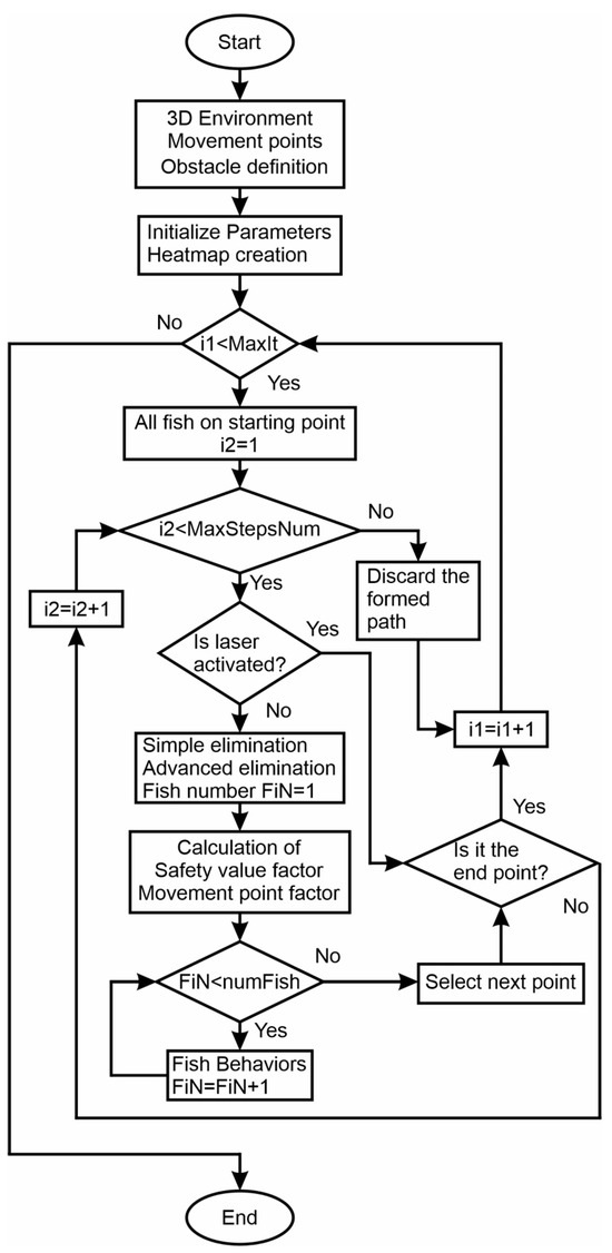
Figure 8.
Improved Artificial Fish Swarm Algorithm combined with a ray casting algorithm flow chart.
Figure 9 shows the flow chart for the proposed multiple laser activation methodology.
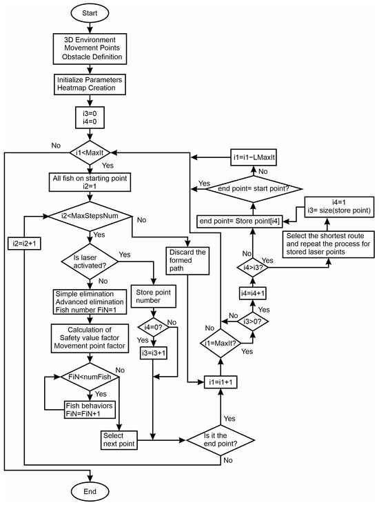
Figure 9.
Multiple laser activation method using the improved Artificial Fish Swarm Algorithm integrated with the ray casting algorithm flow chart.
3. Results
Multiple experiments were conducted to evaluate the performance and the efficiency of solving the path planning problem using the proposed methods. The experiments for our comparison between the proposed methods were performed in the same 3D environment to optimally reflect the response of the algorithm and assess the contribution of each technique. The final algorithm was tested in various environments and applied to real case scenarios for the planning of the path of a quadcopter drone, a CMM, and an industrial robotic arm. The experiments were carried out in a space with 507 points, 13 along the x axis, 13 along the y axis, and 3 along the z axis. In addition, 2 rows of obstacles were placed starting from the 9th row. The end point is located after the obstacle so that the optimal path is forced to pass over the obstacle. An environment with fewer obstacles contains more possible points due to the fact that they are not eliminated by obstacles and the algorithm’s overall behavior can be carefully analyzed.
The exhibited tests are intended to compare the methodologies. Thus, the environmental conditions and parameters were kept the same, namely, MaxIt = 90, MaxStepsNum = 40, numFish = 150, fishTryNum = 15, and δ = 0.2 Regarding the creation of the obstacle heatmap, obsHeatVal = 150, heatIncrCoef = 0.4, obsNearHeatVal = 90, obsNearHeatVal2 = 40. The distribution of bonuses was carried out according to the following method. Initially, the heatmap values, hv, were examined in relation to average value mh and distance df of the examined point from the position where the fish is located. If , for the objective function’s value of points, their is multiplied by bh = 1.35 da; this represents the length of the elementary squared parallelepiped. If and for the district points with or , bh = 1.25. If and for the district points with , bh = 0.82. If for the district points with or , bh = 0.82.
The response of each algorithm and its impact on shaping the optimal path are reported in detail. The objective function used for the results reported was Equation (17), without including the proposed safety value factor and the total movement point factor. The contribution of these terms to the path’s formation and the algorithm’s convergence is presented in separate experiments.
Figure 10a depicts the outcome of using the improved AFSA behaviors proposed in [47], here applied to a 3D environment. Figure 10,c show the route resulting from the implementation of the proposed 3D simple and advanced elimination techniques. Figure 11a–c show in diagrams the arithmetic value of the path length for each algorithm’s iterations. The route depicted in Figure 10a shows several unnecessary changes in direction along the z axis. These oscillations caused an increase in the length of the found path. As shown in Figure 10b,c, the 3D elimination of possible movement points led to a reduction of these oscillations and a partial stabilization of the course when the fish were located in an area with few or without obstacles. Oscillations did not disappear completely; however, their amplitude was reduced, as was their influence on the length of the paths that were designed. Using the advanced point elimination method appears to further reduce the length of the path and encourages the selection of points closer to the ending point. Using the simple elimination method compared to AFSA yielded an 8.91% reduction in the total length of the found path, while using the advanced method decreased it by a further 6.68%. Moreover, comparing the results of AFSA and the 3D point elimination methods, a significant reduction in the variation of the formed path length was observed; see Figure 11a–c. Without using the 3D point eliminations, several paths with increased length were formed. Nevertheless, paths of varying lengths were formed closer to the optimal route by using eliminations, which indicates that not only one fixed path was formed but also alternative paths in the surrounding space were explored. The lengths of the generated paths for each methodology are summarized in Table 1.
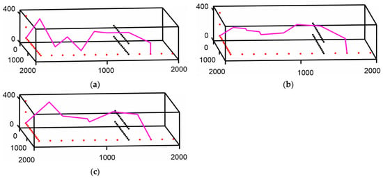
Figure 10.
Formation of the resulting path using AFSA: (a) Resulting path from the improved AFSA; (b) Resulting path from the improved AFSA and simple 3D elimination; (c) Resulting path from the improved AFSA and advanced 3D elimination.
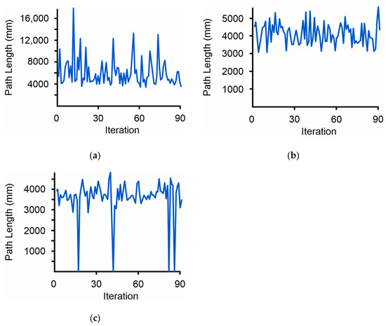
Figure 11.
Path length–iteration diagrams for the environmental condition of Figure 10a–c, respectively: (a) Path length–iteration diagram for the form of the environment of Figure 10a; (b) Path length–iteration diagram for the form of the environment of Figure 10b; (c) Path length–iteration diagram for the form of the environment of Figure 10c.

Table 1.
Path length with and without using 3D Elimination.
Figure 12a shows the results of the formed path by additionally using the heatmap, and Figure 12b shows the results of randomly activating the heat map. Figure 12c,d show the diagrams for each process, respectively. Using the obstacle’s heatmap reduced the oscillations even more and stabilized the path’s course. This benefited the formation of the path, reducing its length by 2.29%, while random activation reduced it by a further 3.82%. Another important advantage of its use, as seen in Figure 12c, was that it enabled the determination of the movement policy of the fish, taking into account the conditions of the environment based on its location in order to optimally enhance the exploration of the possible routes and find the optimal path. Also, in the case of random activation, it was observed that more paths ended up in deadlock and were rejected, but the optimal path was shorter than those in the previous cases.
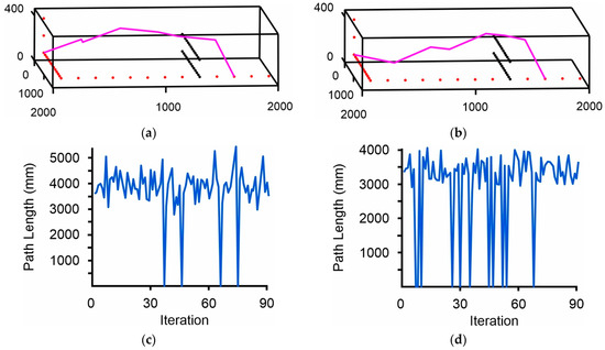
Figure 12.
Path planning results using AFSA and the proposed heatmap methodology: (a) Resulting path using the heatmap; (b) Resulting path from randomly activating the heatmap; (c) Path length–iteration diagram with the heatmap methodology; (d) Path length–iteration diagram with randomly activating the heatmap methodology.
Table 2 summarizes the results.

Table 2.
Length of the formed path using heatmap methods.
Figure 13a,b depict the resulting combination of all the above techniques, adding separately to the objective function the proposed safety value factor and the total movement point factor, respectively. Coefficients w1 and w2 were 1.2 and 0.2, respectively. Figure 13c shows the results of using the entire objective function of Equation (17) with coefficients w1 = 1.8 and w2 = 0.3. Figure 14a–c show the diagrams for each case, respectively. The use of the safety value factor seemed to stabilize the course of the path in the XY plane and reduce its unnecessary oscillations while the obstacles were successfully overcome. The use of the total movement point factor seemed to stabilize the 3D course of the path and diminish the unnecessary oscillations, enabling the fish to maintain a stable course. Both factors appeared to have a similar effect on the length of the formed path, reducing it by about 0.7%, while their simultaneous use led to finding the optimal solution. Table 3 summarizes the results for the described cases.
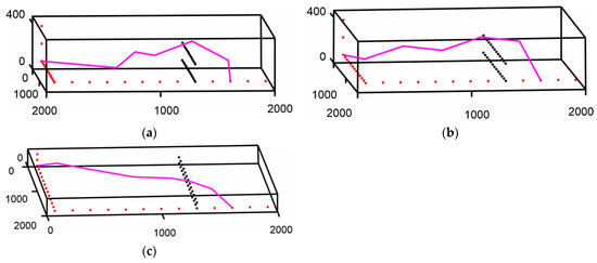
Figure 13.
Formation of the resulting path using proposed AFSA: (a) Resulting path from the improved proposed AFSA and the safety value factor; (b) Resulting path from the improved proposed AFSA and the total movement point factor; (c) Resulting path from the improved proposed AFSA, the safety value factor, and the total movement point factor.
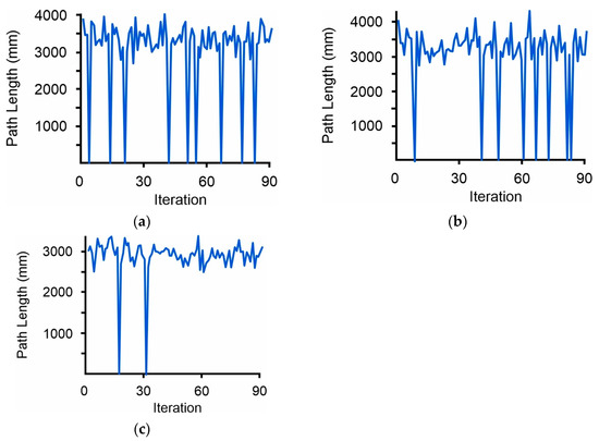
Figure 14.
Path length–iteration diagrams for the environmental condition of Figure 13a–c, respectively: (a) Path length–iteration diagram for the form of the environment of Figure 13a; (b) Path length–iteration diagram for the form of the environment of Figure 13b; (c) Path length–iteration diagram for the form of the environment of Figure 13c.

Table 3.
Path length using the safety and movement point factors.
Figure 15a,b show the results of combining the artificial fish swarm algorithm enhanced with the ray casting algorithm and the multiple laser method, respectively. Figure 15c,d show the lengths of the formed paths during the execution of the algorithm for both cases, respectively. The integration of the laser in this example did not affect the formation of the optimal path because the ending point was very close to the obstacle and the laser was activated from a point that was located within the range of possible movement points of the fish for its movement to the end point. However, the laser activation point favored the model of multiple laser activation in terms of the examined points. Multiple laser activation found an even shorter path, with a length 0.93% shorter than the optimal one. Also important is the fact that the path it found consisted of only three points, which is the minimum number of possible points that can form a path within a 3D grid environment and effectively overcome the obstacles. Furthermore, the final path overcame the limitation set by the model of 24 possible movement points and chose a point that was far away from the original. At the same time, it more realistically simulated the flexibility and movement capabilities of the drones by overcoming the computational limitations posed when solving the optimal path planning problem in a 3D grid environment. Finally, the weaknesses of the effective application of bio-inspired algorithms such as AFSA to choose the next point of movement from among a large number of possible points were overcome. In this example, in order for the fish to be moved from the starting point to a selected intermediate point, if the proposed methodology was not applied, it would have to choose it from among 390 possible movement points. The results are summarized in Table 4.
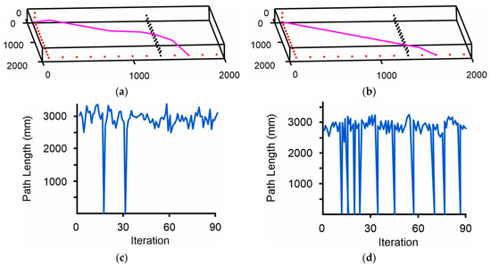
Figure 15.
Path planning results using the proposed enhanced AFSA: (a) Path planning using the proposed AFSA integrated with a ray casting algorithm; (b) Path planning using the proposed AFSA integrated with a ray casting algorithm and multiple laser activation method; (c) Diagram of formed paths using the proposed AFSA integrated with a ray casting algorithm; (d) Diagram of formed paths using the proposed AFSA integrated with a ray casting algorithm and multiple laser activation method.

Table 4.
Path length using the laser and multiple laser methodologies.
Figure 16a,b show the results of the proposed algorithm using the multiple laser beam technique in different 3D environments with predefined obstacles. Figure 16c,d show the path length diagram for each environment, respectively. The 3D environments depicted in Figure 16a,b consist of 900 discrete points, of which 127 and 156 are obstacles. In both cases, the algorithm efficiently found the optimal 3D path using the multiple laser method.
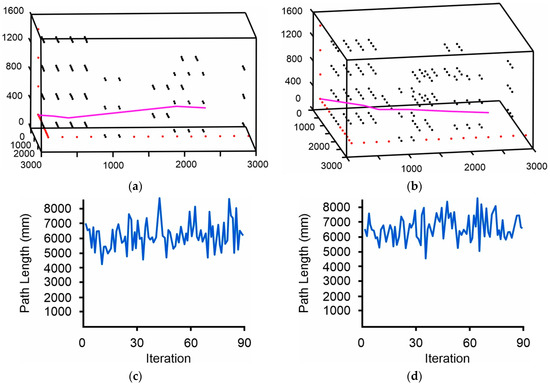
Figure 17a shows the results of the path formation of a state of the art (SOTA) methodology in path planning, the ant colony optimization algorithm, presented in [48]. Figure 17b–d show the final path from the proposed AFSA, the proposed AFSA integrated with the laser beam, and the multiple laser beam algorithm, respectively. The experiments were executed in 14 × 14 × 4 3D grid environment with obstacles. Table 5 summarizes the lengths and the required time of execution of the resulting path for each algorithm. The algorithms in Figure 17a,b used the eight possible movement point model to accomplish the agent’s navigation, whereas those in Figure 17c,d employed the 24 possible movement point model. The comparison was performed using common parameters across all AFSAs, i.e., the same as those described in the Results section. For the proposed AFSA + Multiple Laser Beam algorithm, LMaxIt = 5. The presented time describes the time that the algorithms required without including collective activities such as environmental set up. The reason these procedures are not included is to translate the comparison into straightforward and accurate data. The ant colony optimization algorithm successfully formed a final path, but it was not the optimal one. This was attributed to the fact that there were multiple movement points, the existence of several potential paths that connected the start to the end point, and the fact that the algorithm fell into a locally optimal solution. Also, its execution time was considerably longer than those of the other algorithms. On the other hand, the proposed AFSA found the optimal path, which was 8.05% shorter than the path created by the ant colony optimization algorithm, while its execution time was 57% faster. The integration of laser with the AFSA and the 24 possible movement points further reduced the length of the formed path by 22.18% compared to the ant colony optimization and by 15.36% compared to the proposed AFSA with the 8 possible movement points model, while its execution time was shorter by 80% and 53.96%, respectively. The shorter path was created by the multiple laser beam algorithm, i.e., 23.45% shorter than the ant colony optimization and 16.74% shorter than AFSA with the 8 possible movement points model. Its execution time was reduced by 59.09% and 3.01% compared to the two algorithms, respectively.
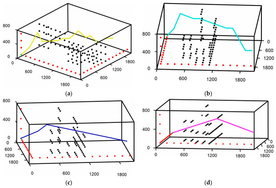
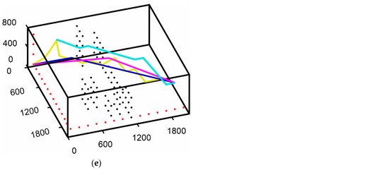
Figure 17.
Formation of the resulting 3D paths: (a) Resulting path from the ant colony optimization [48]; (b) Resulting path from the proposed enhanced AFSA with 8 possible movement point model; (c) Resulting path from the proposed enhanced AFSA integrated with ray casting algorithm; (d) Resulting path from the proposed enhanced AFSA and multiple laser activation; (e) Total path planning results from the algorithms in (a–d).

Table 5.
Path length from Figure 17.
The path length results generated by the ant colony optimization method and proposed AFSA can be considered as an equivalent example of the SOTA algorithm’s results that may fall into a local optimum path solution or successfully find the optimal path in a 3D grid environment [49,50,51]. Thus, as seen by the above comparison of results, the combination of the ray casting algorithm and the multiple laser activation method with the 24 possible movement points model can significantly reduce the length of the optimal path obtained from the SOTA methods. SOTA methods need to be modified appropriately so that they can find the optimal path in a 3D environment using the 24 possible movement point model and the ray casting algorithm integration presented in this paper in order to compare the proposed methodologies more precisely and comprehensively.
Several experiments were conducted in a 3D grid environment with several obstacles in order to compare the four algorithms, i.e., traditional AFSA, named 3D tr-AFSA; the proposed AFSA, 3D pr-AFSA; the proposed AFSA integrated with the ray casting algorithm, 3D laser-AFSA; and the multiple laser beam AFSA, 3D multi-AFSA. In all algorithms, the model of 24 possible movement points was used with common parameter values, i.e., identical to those presented in this section. For the 3D multi-AFSA algorithm, LMaxIt = 5. In Figure 18a–d, the results of the formed paths for 3D tr-AFSA, 3D pr-AFSA, 3D laser-AFSA, and 3D multi-AFSA are presented, respectively. The starting point is shown in green. Table 6 summarizes the results of the maximum acceptable, minimum acceptable, and average lengths of the generated paths during the execution of the algorithms for each method. The lengths of the paths that were not successful and were rejected are excluded from the minimum length recording. The column of percentage reduction contains the reduction percentage of the path length from each algorithm in relation to the most extensive path, i.e., that of 3D tr-AFSA. The values of the maximum, minimum, and average number of nodes from the formed path during the execution of the algorithms are presented in Table 7.
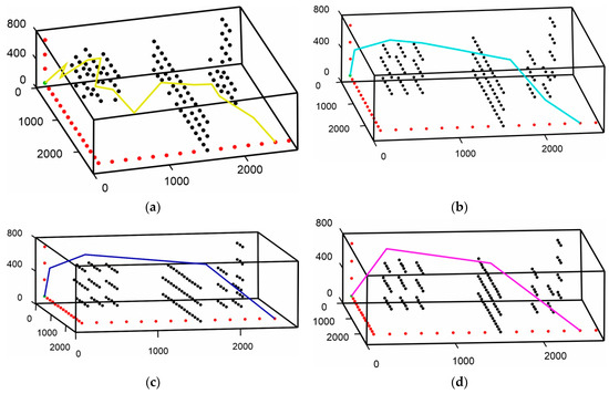
Figure 18.
Formation of 3D paths: (a) Resulting path from 3D tr-AFSA; (b) Resulting path from 3D pr-AFSA; (c) Resulting path from 3D laser-AFSA; (d) Resulting path from 3D multi-AFSA.

Table 6.
Path length from Figure 18.

Table 7.
The maximum, minimum, and average number of nodes from the paths in Figure 18.
Table 6 shows that 3D tr-AFSA formed paths with much higher maximum, minimum, and average lengths than the other algorithms. This implies that due to the high number of possible movement points, the fish unsuccessfully meandered in the 3D environment, forming paths that connected the start to the end point, but they were not optimal. Figure 19 also indicates that the dropout number of 3D tr-AFSA was low. These indications, combined with the high average path length, suggest that during the formation of the paths, several oscillations were encountered, and the fish had difficulty in the selection process of their next movement point. Comparing Figure 18a and Figure 18b, it is observed that 3D tr-AFSA tended to select more points from the 8 possible movement points than the 24, and the point selection of the 24 point model was not always the most beneficial. Table 6 shows that the maximum length of 3D pr-AFSA was reduced by 81% compared to 3D tr-AFSA, and the numerical values of the maximum and minimum path lengths were closest to the average. Moreover, the lower disparity between the minimum and the maximal values of the lengths implies that attempts at route formation were focused on the optimal path. As a result, the employed methodologies favored the choice of the next movement point and helped the swarm to reach its final destination. The 3D pr-AFSA could find the optimal path in a 3D environment. The behavior of 3D laser-AFSA was identical to 3D pr-AFSA, achieving lower values for the maximum, the minimum, and average lengths of the formed paths. The additional reduction was due to the combination of the ray casting algorithm, which formed slightly shorter paths throughout the algorithm’s execution. The 3D multi-AFSA algorithm also exhibited similar behavior to 3D laser-AFSA. Its average value in Table 6 was higher because it included the arithmetic values of multiple repetitions, even from the paths that were rejected. It is noteworthy that the difference between 3D laser-AFSA and 3D multi-AFSA is captured in Table 7 through the arithmetic value of the minimum node number, which was further decreased for the case of 3D multi-AFSA.
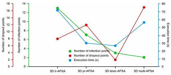
Figure 19.
Diagram showing the numbers of infection points, drop out points, and execution time for 3D tr-AFSA, 3D pr-AFSA, 3D laser-AFSA, and 3D multi-AFSA.
Figure 19 shows that the proposed methodologies adopted in 3D pr-AFSA significantly reduced the execution time of the algorithm in comparison with 3D tr-AFSA, and that the integration of the ray casting algorithm reduced it even further. Although the proposed methodologies required the execution of more calculations, their contribution seemed to importantly affect the algorithm’s convergence speed. The 3D multi-AFSA needed more time to achieve completion compared to 3D pr-AFSA and 3D laser-AFSA. This was due to the fact that it examined more alternative routes and explored the environment more thoroughly, eliminating the memory disadvantage of AFSA, which is particularly profitable in larger environments where 3D laser-AFSA, in some part of the formed path, may not choose the optimal possible solution and may be corrected by the 3D multi-AFSA. Also, as shown in Figure 19, the 3D multi-AFSA displayed the largest number of drop out points. This was due to the fact that the number of additional formed paths was included. If they were not included, its value would have been identical to 3D laser-AFSA. Figure 19 shows a reduction in the infection points of the path as the proposed methodologies were included in the traditional AFSA, which would be particularly important when the formed paths are executed by the robots.
The proposed methodologies were implemented to solve some real-world challenges in robotics. They have been successfully applied to solve a drone path planning problem in real-world conditions, finding the safe, optimal path for conducting measurements by a CMM machine in an environment with multiple components and generating the path for the precise transfer of objects by an industrial robotic arm in an environment with obstacles. A Dji Mavic Air 2 drone (Shenzhen, China) was used for the experiment. Figure 20a shows the environment where the experiment was conducted. The green point shows the drone’s take off location. The drone had to navigate to an end point, shown in orange, without colliding with obstacles such as buildings or trees. Figure 20b shows the modeling of the 3D environment and the results after running the algorithm using multiple laser activation. Figure 20c shows the path length diagram and Figure 20d depicts the drone implemented for this scenario.
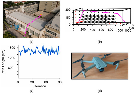
Figure 20.
The suggested approach applied to drone’s 3D path planning: (a) Real-world environment of the drone scenario; (b) Resulting 3D path using 3D multi-AFSA; (c) Diagram of formed paths for (b); (d) The drone used for the execution of this scenario; the model was Dji mavic air 2.
It is a common occurrence in the manufacturing production process to increase the efficiency of CMM to have more than one piece in a machine’s operating area during the measurement process. CMMs are highly sensitive, and any contact with an object during the relocation of their probe from one component to another may cause damage to the machine or require a mandatory restart and remeasuring procedure. This kind of error can significantly slow down the execution of the process and the production cycle. Figure 21a–l exhibits the outcomes of utilizing the suggested methodologies to solve the 3D path planning problem for the safe navigation of a CMM probe to components where the measurements were to be conducted. Figure 21a shows the CMM used for the experiments. Figure 21b illustrates the arrangement of the objects, the components that the measuring procedure would interact with, and the collision free path that the machine would follow. The parts to be measured were numbered and the sequence in which the measurements were performed was predetermined. Letters A and B were used for parts that were not measured in the current research but which were located in the operation space. The different colors of the path indicate the individual parts of the path during the transfer from one target area to the next. Figure 21c–k show the CMM probe position during the execution of the path. Figure 21l shows the path formed by the proposed methodology. It is worth noting that during the environment modeling to ensure that the formed path could be executed without any part of the CMM colliding with the obstacles, the components were represented as solid volumes. A characteristic example of this process is part A, where if it was modeled exactly as it is in the real world, the generated optimal path would pass underneath and not above it, resulting in the parts colliding with the section of CMM that moves the probe vertically.
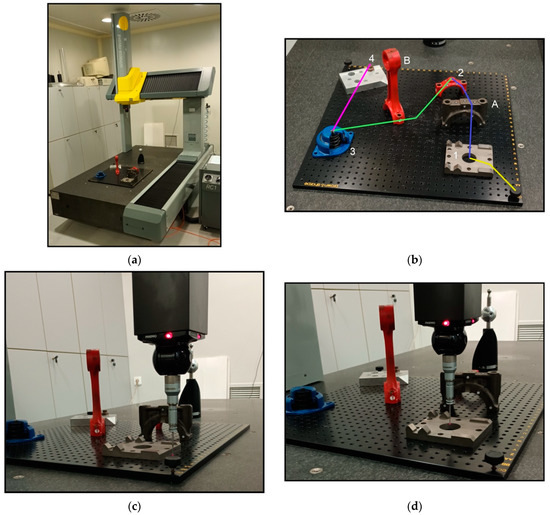
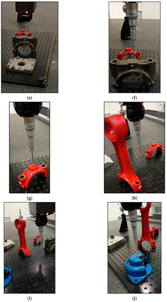
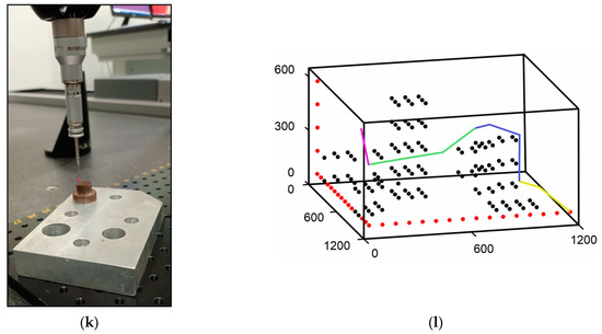
Figure 21.
Application of the proposed method to CMM 3D path planning: (a) Coordinate Measuring Machine (CMM); (b) Real-world experimental environment; (c–k) CMM probe positions during path execution; (l) Path planning results and environment modeling using the proposed 3D multi-AFSA.
Industrial robotic arms are extensively used in factories for transferring items from one location to another. A key aspect of successfully and optimally accomplishing this task is the path planning of the end effector on the robotic arm. In this experiment, the proposed algorithm was used to determine the sequence of points from a start to an end position in a 3D environment with obstacles. The simulation was performed in order to examine if the proposed methodology could be obtained to solve real-world manufacturing problems. The experiments were conducted using an industrial robotic arm with 6 degrees of freedom, i.e., the Kawasaki RS010N (Minato, Tokyo, Japan).
Figure 22a shows the general experimental setup, the robotic arm, the obstacles, the and the start and end positions. The optimal path to be executed by the robot is shown in magenta. The purpose of this task was to safely navigate the robot’s end effector while simultaneously carrying a small object. A pneumatic gripper was used on the robot’s end effector in order to manipulate the small object. The operation space consisted of two obstacles while the end position was located slightly higher in elevation than the start position. Figure 22b–d shows the robotic arm reaching an intermediate location in the path. Figure 22e exhibits the results of the multiple laser beam algorithm execution. The thickness of the obstacles was considerably less than the rest of the operation area, so a dense mesh was used. The proposed algorithm successfully coped with this task, while the number of points given to the robotic arm for its execution was the minimum possible.
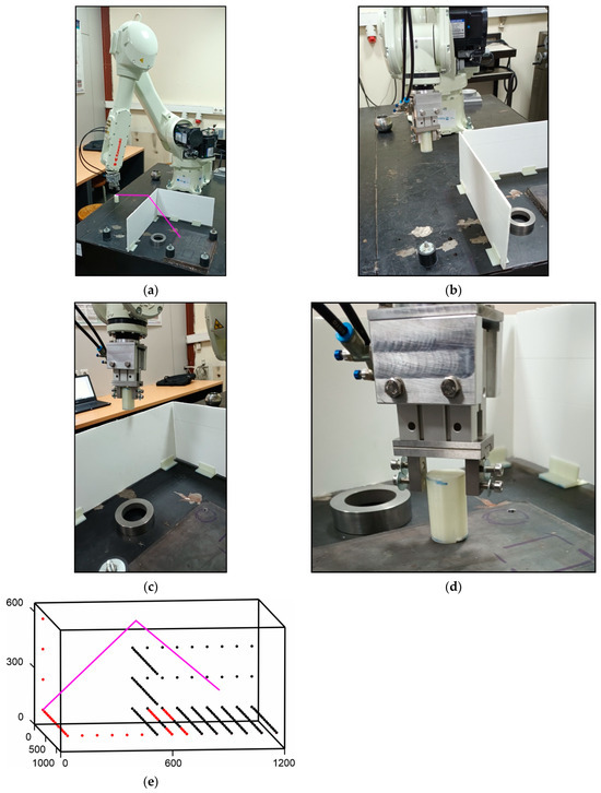
Figure 22.
The suggested approach applied to the 3D path planning of an industrial robotic arm: (a) Real-world environment scenario with an industrial robot; (b–d) Interim locations of the resultant path execution of the industrial robotic arm; (e) Path planning results and environment modeling using the proposed 3D multi-AFSA.
4. Discussion
Searching for the optimal path in a 3D complex environment with obstacles is an intertemporal challenge for the effective navigation of mechatronic systems and especially for drones. The application of the artificial fish swarm algorithm using the model of 24 possible nearby movement points in a 3D grid environment with obstacles was the main research concern of the present study. Finding the optimal path was achieved taking into account the drone’s movement capabilities and flexibility.
A number of methodologies were developed and tested to achieve this endeavor. The simple and the advanced 3D elimination of possible movement points during the process of selecting the next movement point, as described in this paper, was shown to be highly effective. Their combination was able to reduce the length of the formed path by 15% and focus the search of the fish on routes that were close to the optimal path, thereby reducing unnecessary wandering in the environment.
The 3D implementation of the obstacle heatmap stabilized the course of the fish during the execution of the algorithm, reduced unnecessary oscillations, and provided the possibility of creating navigation policies on a map based on the density, size, and position of obstacles in the environment. In this way, alternative routes can be explored in the different areas of the map and the exploring capabilities of the fish are increased.
The proposed safety value factor and the total movement point factor contributed to obstacle avoidance, reduced unnecessary oscillations, maintained the direction of the fish, and led to the finding of the optimal path.
The combination of the artificial fish swarm algorithm with the ray casting algorithm reduced the length of the optimal path. The reduction rate depended on the location of the end point and its proximity to obstacles. It also played an important role in the creation of the proposed methodology of multiple laser activations. The methods of multiple laser activation solved one of the main issues of the utilization of the artificial fish swarm algorithm in the path planning problem, i.e., the lack of a memory structure. Moreover, it reduced the number of points and the length of the optimal path. Its reduction rate depended on the location of the start and end points, as well as the shape and the obstacles of the 3D environment. Finally, it solved the problem of the artificial fish swarm algorithm and other bio-inspired algorithms to navigate successfully and select their next point of movement among a larger number of points. Without increasing the number of possible points, it provided the capability of selecting as the next point in the path, i.e., one that may have been located far away from the current location of the fish.
- The proposed approach can successfully found the optimal path in a 3D environment with obstacles. Nevertheless, there are some restrictions, which are specified below:
- The parameters and strategies for distributing the bonuses and penalties in the heatmap methodology are not tuned by any intelligent algorithmic method. Therefore, erroneous actions may impact the algorithm’s convergence.
The provided methodologies can be utilized for the enhancement of other path planning algorithms and could be further extended to positively enrich existing scientific knowledge. Suggestions for future research may include addressing the limitations and the application of the algorithm to online path planning cases.
Author Contributions
Conceptualization, I.C., G.M., V.P., M.T.M. and A.T.; methodology, I.C., G.M., V.P., M.T.M. and A.T.; software, I.C., V.P. and M.T.M.; validation, G.M. and A.T.; formal analysis, G.M. and A.T.; investigation, I.C., G.M., V.P., M.T.M. and A.T.; data curation, G.M., M.T.M. and A.T.; writing—original draft preparation, I.C., G.M., V.P., M.T.M. and A.T.; writing—review and editing, I.C., G.M., V.P., M.T.M. and A.T.; visualization, I.C., V.P. and M.T.M.; supervision, G.M., M.T.M. and A.T.; project administration, G.M. All authors have read and agreed to the published version of the manuscript.
Funding
This research received no external funding.
Data Availability Statement
Data will be available upon request from the corresponding authors.
Conflicts of Interest
The authors declare no conflicts of interest.
References
- Jin, Z.; Bai, Y.; Song, W.; Yu, Q.; Yue, X.; Jia, X. DVRT: Design and Evaluation of a Virtual Reality Drone Programming Teaching System. Comput. Graph. 2024, 125, 104114. [Google Scholar] [CrossRef]
- Perera, S.; Nalani, H. UAVS for a Complete Topographic Survey. Int. Arch. Photogramm. Remote Sens. Spat. Inf. Sci. 2022, XLIII-B2-2022, 441–447. [Google Scholar] [CrossRef]
- Huang, X.; Wang, G. Optimization for Total Energy Consumption of Drone Inspection Based on Distance-Constrained Capacitated Vehicle Routing Problem: A Study in Wind Farm. Expert. Syst. Appl. 2024, 255, 124880. [Google Scholar] [CrossRef]
- Hoang, M.-T.; Grøntved, K.; van Berkel, N.; Skov, M.; Christensen, A.; Merritt, T. Drone Swarms to Support Search and Rescue Operations: Opportunities and Challenges. In Cultural Robotics: Social Robots and Their Emergent Cultural Ecologies; Springer: Cham, Switzerland, 2023; pp. 163–176. ISBN 978-3-031-28137-2. [Google Scholar]
- Grigore, L.; Cristescu, C. The Use of Drones in Tactical Military Operations in the Integrated and Cybernetic Battlefield. Land. Forces Acad. Rev. 2024, 29, 269–273. [Google Scholar] [CrossRef]
- Dasari, S.; Gupta, S. Application of Fractal Analysis in Evaluation of Urban Road Networks in Small Sized City of India: Case City of Karimnagar. Transp. Res. Procedia 2020, 48, 1987–1997. [Google Scholar] [CrossRef]
- Qu, C.; Gai, W.; Zhang, J.; Zhong, M. A Novel Hybrid Grey Wolf Optimizer Algorithm for Unmanned Aerial Vehicle (UAV) Path Planning. Knowl.-Based Syst. 2020, 194, 105530. [Google Scholar] [CrossRef]
- Bayliss, C.; Martins, L.d.C.; Juan, A.A. A Two-Phase Local Search with a Discrete-Event Heuristic for the Omnichannel Vehicle Routing Problem. Comput. Ind. Eng. 2020, 148, 106695. [Google Scholar] [CrossRef]
- Deng, X.; Li, R.; Zhao, L.; Wang, K.; Gui, X. Multi-Obstacle Path Planning and Optimization for Mobile Robot. Expert. Syst. Appl. 2021, 183, 115445. [Google Scholar] [CrossRef]
- Zhang, Z.; Wu, L.; Zhang, W.; Peng, T.; Zheng, J. Energy-Efficient Path Planning for a Single-Load Automated Guided Vehicle in a Manufacturing Workshop. Comput. Ind. Eng. 2021, 158, 107397. [Google Scholar] [CrossRef]
- Chou, J.S.; Cheng, M.Y.; Hsieh, Y.M.; Yang, I.T.; Hsu, H.T. Optimal Path Planning in Real Time for Dynamic Building Fire Rescue Operations Using Wireless Sensors and Visual Guidance. Autom. Constr. 2019, 99, 1–17. [Google Scholar] [CrossRef]
- Wu, L.; Huang, X.; Cui, J.; Liu, C.; Xiao, W. Modified Adaptive Ant Colony Optimization Algorithm and Its Application for Solving Path Planning of Mobile Robot. Expert. Syst. Appl. 2023, 215, 119410. [Google Scholar] [CrossRef]
- Li, Y.; Chen, H.; Joo Er, M.; Wang, X. Coverage Path Planning for UAVs Based on Enhanced Exact Cellular Decomposition Method. Mechatronics 2011, 21, 876–885. [Google Scholar] [CrossRef]
- Ning, Y.; Zhang, F.; Jin, B.; Wang, M. Three-Dimensional Path Planning for a Novel Sediment Sampler in Ocean Environment Based on an Improved Mutation Operator Genetic Algorithm. Ocean. Eng. 2023, 289, 116142. [Google Scholar] [CrossRef]
- Wang, X.; Gao, J.; Zhou, X.; Gu, X. Path Planning for the Gantry Welding Robot System Based on Improved RRT*. Robot. Comput. Integr. Manuf. 2024, 85, 102643. [Google Scholar] [CrossRef]
- Sathiya, V.; Chinnadurai, M.; Ramabalan, S. Mobile Robot Path Planning Using Fuzzy Enhanced Improved Multi-Objective Particle Swarm Optimization (FIMOPSO). Expert. Syst. Appl. 2022, 198, 116875. [Google Scholar] [CrossRef]
- Liang, J.H.; Lee, C.H. Efficient Collision-Free Path-Planning of Multiple Mobile Robots System Using Efficient Artificial Bee Colony Algorithm. Adv. Eng. Softw. 2015, 79, 47–56. [Google Scholar] [CrossRef]
- Xie, X.; Tang, Z.; Cai, J. The Multi-Objective Inspection Path-Planning in Radioactive Environment Based on an Improved Ant Colony Optimization Algorithm. Prog. Nucl. Energy 2022, 144, 104076. [Google Scholar] [CrossRef]
- Chen, H.; Chen, S.; Wen, C.Y.; Lu, P. A Fast Planning Approach for 3D Short Trajectory with a Parallel Framework. Mechatronics 2024, 97, 103094. [Google Scholar] [CrossRef]
- Liu, Y.; Feng, X.; Zhang, L.; Hua, W.; Li, K. A Pareto Artificial Fish Swarm Algorithm for Solving a Multi-Objective Electric Transit Network Design Problem. Transp. A Transp. Sci. 2020, 16, 1648–1670. [Google Scholar] [CrossRef]
- Zong, X.; Fan, X.; Jiang, Y.; Du, J.; Wang, Y. Simulation Model of Emergency Evacuation Based on Artificial Fish Swarm Algorithm. In Proceedings of the 13th International Conference on Computer Science and Education, ICCSE 2018, Colombo, Sri Lanka, 8–11 August 2018; pp. 263–268. [Google Scholar] [CrossRef]
- Zhang, Y.; Hua, Y. Path Planning of Mobile Robot Based on Hybrid Improved Artificial Fish Swarm Algorithm. Vibroengineering Procedia 2018, 17, 130–136. [Google Scholar] [CrossRef][Green Version]
- Li, W.; Bi, Y.; Zhu, X.; Yuan, C.-A.; Zhang, X.-B. Hybrid Swarm Intelligent Parallel Algorithm Research Based on Multi-Core Clusters. Microprocess. Microsyst. 2016, 47, 151–160. [Google Scholar] [CrossRef]
- Fang, N.; Zhou, J.; Zhang, R.; Liu, Y.; Zhang, Y. A Hybrid of Real Coded Genetic Algorithm and Artificial Fish Swarm Algorithm for Short-Term Optimal Hydrothermal Scheduling. Int. J. Electr. Power Energy Syst. 2014, 62, 617–629. [Google Scholar] [CrossRef]
- Peng, J.; Li, X.; Qin, Z.Q.; Luo, G. Robot Global Path Planning Based on Improved Artificial Fish-Swarm Algorithm. Res. J. Appl. Sci. Eng. Technol. 2013, 5, 2042–2047. [Google Scholar] [CrossRef]
- Qi, Y.; Zhi, P.; Ye, H.; Zhu, W. Research on Lifetime Optimization of Unmanned Ship Lithium Battery Pack Power Supply System Based on Artificial Fish Swarm Algorithm. In Proceedings of the 39th Chinese Control Conference (CCC), Shenyang, China, 27–29 July 2020; pp. 5379–5384. [Google Scholar] [CrossRef]
- Xu, H.; Zhao, Y.Q.; Ye, C.; Lin, F. Integrated Optimization for Mechanical Elastic Wheel and Suspension Based on an Improved Artificial Fish Swarm Algorithm. Adv. Eng. Softw. 2019, 137, 102722. [Google Scholar] [CrossRef]
- Mavrovouniotis, M.; Li, C.; Yang, S. A Survey of Swarm Intelligence for Dynamic Optimization: Algorithms and Applications. Swarm Evol. Comput. 2017, 33, 1–17. [Google Scholar] [CrossRef]
- Yazdani, D.; Sepas-Moghaddam, A.; Dehban, A.; Horta, N. A Novel Approach for Optimization in Dynamic Environments Based on Modified Artificial Fish Swarm Algorithm. Int. J. Comput. Intell. Appl. 2016, 15, 1650010. [Google Scholar] [CrossRef]
- Yaseen, Z.M.; Karami, H.; Ehteram, M.; Mohd, N.S.; Mousavi, S.F.; Hin, L.S.; Kisi, O.; Farzin, S.; Kim, S.; El-Shafie, A. Optimization of Reservoir Operation Using New Hybrid Algorithm. KSCE J. Civ. Eng. 2018, 22, 4668–4680. [Google Scholar] [CrossRef]
- Zhang, L.; Fu, M.; Li, H.; Liu, T. Improved Artificial Bee Colony Algorithm Based on Damping Motion and Artificial Fish Swarm Algorithm. J. Phys. Conf. Ser. 2021, 1903, 012038. [Google Scholar] [CrossRef]
- Zheng, R.; Feng, Z.; Shi, J.; Jiang, S.; Tan, L. Hybrid Bacterial Forging Optimization Based on Artificial Fish Swarm Algorithm and Gaussian Disturbance. In Communications in Computer and Information Science, Proceedings of the International Conference on Bio-Inspired Computing: Theories and Applications, Zhengzhou, China, 22–25 November 2019; Springer: Singapore, 2020; Volume 1159, pp. 124–134. [Google Scholar] [CrossRef]
- Fang, Z.; Hu, L.; Qin, L.; Mao, K.; Chen, W.; Fu, X. Estimation of Ultrasonic Signal Onset for Flow Measurement. Flow. Meas. Instrum. 2017, 55, 1–12. [Google Scholar] [CrossRef]
- Guo, Q.; Xu, R.; Yang, T.; He, L.; Cheng, X.; Li, Z.; Yang, J.G. Application of GRAM and AFSACA-BPN to Thermal Error Optimization Modeling of CNC Machine Tools. Int. J. Adv. Manuf. Technol. 2016, 83, 995–1002. [Google Scholar] [CrossRef]
- Zhuang, D.Y.; Ma, K.; Tang, C.A.; Liang, Z.Z.; Wang, K.K.; Wang, Z.W. Mechanical Parameter Inversion in Tunnel Engineering Using Support Vector Regression Optimized by Multi-Strategy Artificial Fish Swarm Algorithm. Tunn. Undergr. Space Technol. 2019, 83, 425–436. [Google Scholar] [CrossRef]
- Zhou, J.; Qi, G.; Liu, C. A Chaotic Parallel Artificial Fish Swarm Algorithm for Water Quality Monitoring Sensor Networks 3D Coverage Optimization. J. Sens. 2021, 2021, 5529527. [Google Scholar] [CrossRef]
- Dey, U.; Sen, S.; Kumar, C.S.; Jacob, C. Path Planning of Micromanipulators inside an SEM and 3D Nanomanipulation of CNTs for Nanodevice Construction. Mechatronics 2024, 101, 103196. [Google Scholar] [CrossRef]
- Tan, L.; Zhang, H.; Shi, J.; Liu, Y.; Yuan, T. A Robust Multiple Unmanned Aerial Vehicles 3D Path Planning Strategy via Improved Particle Swarm Optimization. Comput. Electr. Eng. 2023, 111, 108947. [Google Scholar] [CrossRef]
- Zhang, N.; Zhang, M.; Low, K.H. 3D Path Planning and Real-Time Collision Resolution of Multirotor Drone Operations in Complex Urban Low-Altitude Airspace. Transp. Res. Part. C Emerg. Technol. 2021, 129, 103123. [Google Scholar] [CrossRef]
- Colas, F.; Mahesh, S.; Pomerleau, F.; Liu, M.; Siegwart, R. 3D Path Planning and Execution for Search and Rescue Ground Robots. In Proceedings of the IEEE/RSJ International Conference on Intelligent Robots and Systems, Tokyo, Japan, 3–7 November 2013; pp. 722–727. [Google Scholar] [CrossRef]
- Wang, Y.; Wang, H.; Liu, Y.; Wu, J.; Lun, Y. 6-DOF UAV Path Planning and Tracking Control for Obstacle Avoidance: A Deep Learning-Based Integrated Approach. Aerosp. Sci. Technol. 2024, 151, 109320. [Google Scholar] [CrossRef]
- Candeloro, M.; Lekkas, A.; Hegde, J.; Sørensen, A. A 3D Dynamic Voronoi Diagram-Based Path-Planning System for UUVs. In Proceedings of the OCEANS 2016 MTS/IEEE Monterey, Monterey, CA, USA, 19–23 September 2016. [Google Scholar]
- De Filippis, L.; Guglieri, G.; Quagliotti, F. Path Planning Strategies for UAVS in 3D Environments. J. Intell. Robot. Syst. 2012, 65, 247–264. [Google Scholar] [CrossRef]
- Zhaoying, L.; Yuheng, F.; Ruoling, S. UAV 3D Trajectory Planning and Optimization Using A* Algorithm Based on Free Space Method. Unmanned Syst. 2023, 12, 457–476. [Google Scholar] [CrossRef]
- Huang, Y.; Huang, S.; Wang, H.; Meng, R. 3D Path Planning and Obstacle Avoidance Algorithms for Obstacle-Overcoming Robots. arXiv 2022, arXiv:2209.00871. [Google Scholar]
- Han, J. An Efficient Approach to 3D Path Planning. Inf. Sci. 2019, 478, 318–330. [Google Scholar] [CrossRef]
- Chouridis, I.; Mansour, G.; Tsagaris, A. Three-Dimensional Path Planning Optimization for Length Reduction of Optimal Path Applied to Robotic Systems. Robotics 2024, 13, 178. [Google Scholar] [CrossRef]
- Mansour, G.; Chouridis, I.; Tsagaris, A. Finding the Optimal Path in a 3D Environment with Predefined Obstacles. Int. J. Adv. Mechatron. Syst. 2024, 11, 50–62. [Google Scholar] [CrossRef]
- Zhang, C.; Zhang, D.; Zhang, M.; Zhang, J.; Mao, W. A Three-Dimensional Ant Colony Algorithm for Multi-Objective Ice Routing of a Ship in the Arctic Area. Ocean. Eng. 2022, 266, 113241. [Google Scholar] [CrossRef]
- Cao, L.; Wang, L.; Liu, Y.; Yan, S. 3D Trajectory Planning Based on the Rapidly-Exploring Random Tree–Connect and Artificial Potential Fields Method for Unmanned Aerial Vehicles. Int. J. Adv. Robot. Syst. 2022, 19, 17298806221118867. [Google Scholar] [CrossRef]
- Kareem, A.A.; Mohamed, M.J.; Oleiwi, B.K. Unmanned Aerial Vehicle Path Planning in a 3D Environment Using a Hybrid Algorithm. Bull. Electr. Eng. Inform. 2024, 13, 905–915. [Google Scholar] [CrossRef]
Disclaimer/Publisher’s Note: The statements, opinions and data contained in all publications are solely those of the individual author(s) and contributor(s) and not of MDPI and/or the editor(s). MDPI and/or the editor(s) disclaim responsibility for any injury to people or property resulting from any ideas, methods, instructions or products referred to in the content. |
© 2025 by the authors. Licensee MDPI, Basel, Switzerland. This article is an open access article distributed under the terms and conditions of the Creative Commons Attribution (CC BY) license (https://creativecommons.org/licenses/by/4.0/).