Abstract
The deployment of robotic systems in hazardous and magnetically intense environments requires careful assessment of their performance under external disturbances. In particular, electromagnetic motors used for actuation may interact with strong magnetic fields, potentially impairing their functionality. This study investigates the behaviour of miniature brushed coreless Direct Current (DC) motors for small Unmanned Aerial Vehicle (UAV) applications in magnetically harsh environments, such as underground accelerator facilities like the Large Hadron Collider (LHC) at CERN. Experimental tests were conducted measuring four main physical quantities: the torque components acting along the axes orthogonal to the shaft, the torque about the shaft axis, variations in angular speed, and electrical current consumption. The results showed that the motors were able to operate under external magnetic field intensities up to 0.4 T, although measurable torques acted on the internal permanent magnet and on the ferromagnetic housing material. Some discrepancies and speed fluctuations were observed during operation and were attributed to mobility of the internal permanent magnet. Overall, the findings demonstrate that the tested miniature motors exhibit resilience in high magnetic fields but suffer from manufacturing variability, suggesting that higher-quality motors with more consistent characteristics would be preferable for reliable robotic operation in harsh environments.
1. Introduction
Recently, the employment of robotic systems in hazardous environments has been extensively studied and tested, as it offers several benefits such as preserving human health, reducing operational time, increasing productivity, and enabling continuous monitoring of critical parameters [1,2]. The environments considered in these robotic application studies include oil and gas sites [3], search and rescue scenarios [4], deep mining operations [5], space exploration [6], nuclear facilities [7] and underwater exploration [8].
This paper focuses on environments that pose challenges due to strong magnetic fields, which can significantly interfere with electrical actuated robotic systems. Examples of such environments are the experimental tokamak nuclear fusion reactor at the International Thermonuclear Experimental Reactor (ITER) [9,10,11] and the Large Hadron Collider (LHC) at the European Organization for Nuclear Research (CERN) [12]. The ITER reactor is based on a tokamak design, a toroidal magnetic confinement device that creates and sustains a plasma state where fusion reactions occur [9]. The LHC, instead, hosts several large-scale detectors, including ATLAS [13], ALICE [14], CMS [15], and LHCb [16], each designed to study different particles and interactions.
Both ITER and the CERN detectors employ powerful magnets that present significant challenges for the deployment of robotic systems. For instance, ATLAS at CERN uses a system of four superconducting magnets, including the world’s largest Nb–Ti (Niobium–Titanium alloy) Barrel Toroid (BT), which produces a magnetic field of about 2 T in its central tracking volume [17]. ITER, in contrast, employs 18 Nb3Sn (Niobium–tin alloy) Toroidal Field (TF) coils capable of generating up to 11.8 T on the plasma axis [18]. These order-of-magnitudes illustrate the extreme magnetic environments that robotic systems may encounter in the vicinity of such devices.
This work is motivated by an ongoing Research and Development (R&D) program at CERN, which aims at deploying robotic systems inside detector experimental caverns [19]. Among the various subprojects, particular attention has been devoted to the use of Lighter-than-Air (LtA) Unmanned Aerial Vehicles (UAVs), such as blimps, for monitoring and inspection purposes [20]. The use of UAVs for cave and underground exploration is a highly active research topic, with several recent studies highlighting their potential and challenges [21,22].
For indoor blimp applications, minimizing weight is a critical requirement to balance payload capacity with buoyancy. As a result, the propulsion system must rely on miniature motors that are both lightweight and efficient [23]. Such characteristics can be provided by Direct Current (DC) motors. In the current CERN robotic airship design for detector cavern operations [24], the propulsion system employs 7 mm diameter, 16 mm length brushed coreless DC motors (see Figure 1). Coreless DC motors, also known as ironless or slotless, features skewed windings embedded in an epoxy resin matrix instead of a conventional iron-core armature, which makes them attractive for applications demanding lightweight, compact, and agile actuation solutions, while also ensuring high efficiency [25]. These actuators offer several advantages for lightweight aerial platforms: low power consumption suitable for battery-driven devices, compact geometry that allows integration in confined spaces, and a high torque-to-size ratio that enables responsive and precise control. Such characteristics make them attractive not only for blimps but also for other compact robotic systems, including the Crazyflie nano-drone, which has demonstrated the suitability of these motors for precision applications [26].
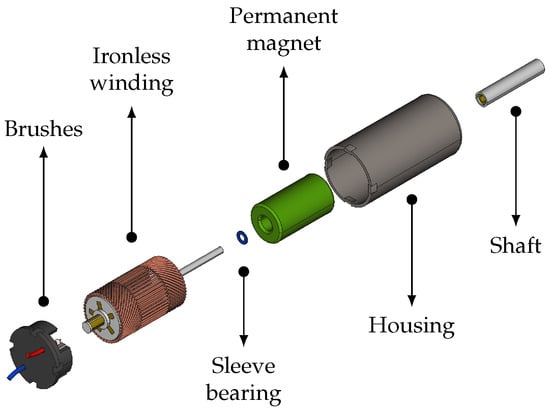
Figure 1.
Schematic of a brushed ironless DC motor. The main components are indicated, including brushes, ironless winding, sleeve bearing, permanent magnet, housing, and shaft.
Compared to traditional iron-core DC motors, coreless architectures eliminate the ferromagnetic armature, resulting in significantly lower rotor inertia, reduced magnetic losses, and smoother torque generation. Importantly for our application, the absence of iron also makes coreless motors intrinsically less susceptible to external magnetic fields, thereby reducing unwanted magnetic interactions during operation inside the cavern environment.
While these favourable characteristics make such actuators well suited for lightweight robotic applications, operating them in environments such as those at CERN introduces significant challenges. Strong external magnetic fields can substantially alter the behaviour of DC motors, giving rise to electromagnetic interactions (forces and torques) that may degrade performance and compromise the reliable operation of the entire robotic system. These effects can have a non-negligible impact on the overall performance and, in the most critical cases, may even result in the loss of the robot.
Little effort has been devoted by the research community and industry to studying the behaviour of DC motors operating within strong magnetic fields, which represents the overall goal of the present work. The first study found in the literature dates back to 2010, when Yun et al. [27] investigated the behaviour of brushed permanent magnet DC motors used in multileaf collimator (MLC) systems for real-time image-guided radiotherapy. In their experiments, motor speed and current were measured under external magnetic fields up to 2000 G (0.2 T) generated by an Electronic Expansion Valve (EEV) electromagnet, with tests conducted for three different motor orientations to reproduce possible installation or rotation configurations. The results showed that in most cases the magnetic encoder failed before any damage occurred to the gearbox or the motor itself, thus defining an upper limit for safe operation. Since fringe magnetic fields in linear accelerator–magnetic resonance (linac–MR) systems are expected to exceed these tolerance levels, the authors concluded that magnetic shielding would be required. In other studies, Heggo et al. [28,29,30], analyzed the effects of high electrostatic and external magnetic fields on inspection UAVs for the monitoring of offshore high-voltage DC (HVDC) wind farms. In particular, the impact of an external magnetic field of 77 mT on the operation of a quadcopter’s propulsion Brushless DC (BLDC) motors was assessed, showing that the direct torque control (DTC) algorithm was unable to keep the system stable under such conditions.
None of these studies addressed the mechanical interactions themselves. In particular, no prior work has quantified the disturbance forces and torques induced on the motors, which is a critical aspect in our context, since even small torque perturbations can compromise the stability and control of a robotic platform. To fill this gap, the present work investigates the electromagnetic interactions between external magnetic fields and DC motor components. The study contributes novel insights by experimentally evaluating the response of miniature DC motors in magnetically harsh environments, such as those encountered at CERN.
The remainder of this paper is organized as follows. Section 2 details the methodology adopted in this work and is divided into three parts: Section 2.1 describes the experimental setup, Section 2.2 outlines the measurement procedure, and Section 2.3 introduces the theoretical framework. The results are presented in Section 3, which is structured into four parts: Section 3.1 analyses the torque measurements acting orthogonally to the motor axis; Section 3.2 presents the torque measured around the motor axis; Section 3.3 discusses the observed variations in angular speed; and Section 3.4 reports the electrical current consumption during the tests. A broader discussion of the findings and their implications is provided in Section 4, while conclusions and future perspectives are summarized in Section 5.
2. Materials and Methods
2.1. Experimental Setup
The experimental campaign was carried out on small brushed coreless DC motors exposed to controlled external magnetic fields, reproducing conditions similar to those encountered by a UAV operating inside the underground facilities of the CERN particle detectors. During the tests, the following quantities were measured and analysed:
- 1.
- Torque orthogonal to the motor axis;
- 2.
- Torque about the motor axis;
- 3.
- Angular velocity of the propeller;
- 4.
- Electrical current consumption.
To measure these quantities, a dedicated experimental apparatus was developed (Figure 2) and positioned inside a high-field electromagnet capable of generating magnetic fields up to 0.5 T (Figure 3a), thus enabling controlled exposure of the motor to external magnetic disturbances. The motors used in this study (Figure 3b) have their specifications reported in Table 1. The setup allows precise adjustment of the motor orientation through a manual goniometer, supported by a custom-designed frame that maintains the goniometer axis perpendicular to the magnetic field lines. A torque sensor is mounted on the goniometer axis, providing measurements with a resolution of N·m. A custom motor holder is rigidly connected to the sensor shaft, ensuring that the mechanical torques acting on the motor are directly transferred to the sensor for accurate measurement. The main components of the experimental setup, along with their models and specifications, are summarized in Table 2.
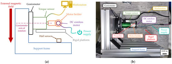
Figure 2.
Experimental setup used to measure the torque exerted on the DC motor by the external magnetic field. (a) Schematic illustration of the apparatus. (b) Lateral view of the experimental setup.
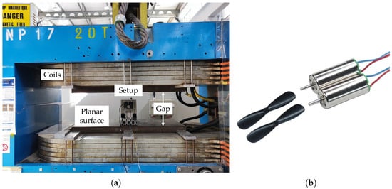
Figure 3.
(a) The MNP17 electromagnet used to generate and control the magnetic field. (b) Photograph of the tested 7 × 16 mm brushed coreless DC motors with propellers.

Table 1.
Relevant specifications of the 7 × 16 mm brushed coreless motors.

Table 2.
Key components of the experimental apparatus.
The test assumes that the applied magnetic field is uniform across the setup and oriented orthogonally to the goniometer axis. To validate this assumption, electromagnetic simulations of the MNP17 magnet were carried out using CST Studio Suite® 2022 (Dassault Systèmes, Vélizy-Villacoublay, France). As illustrated in Figure 4, the planar pole surface (1 m × 0.5 m with a 0.3 m gap) ensures negligible fringe effects at the center (Figure 4a). Fringe effects refer to the non-uniformities of the magnetic field that occur near the edges of the magnet poles, where the field lines spread outward rather than remaining parallel. Figure 4b shows that the volume characterized by uniform field intensity extends beyond the apparatus dimensions (0.15 m × 0.15 m × 0.25 m), thereby supporting the validity of the uniform-field assumption within the measurement region. In addition, a point measurement was taken at the motor location using a Hall probe to verify field magnitude before data acquisition. All components of the test apparatus are made of materials that are expected not to affect the local magnetic field within the measurement region occupied by the motor, further supporting the assumption of a uniform field.
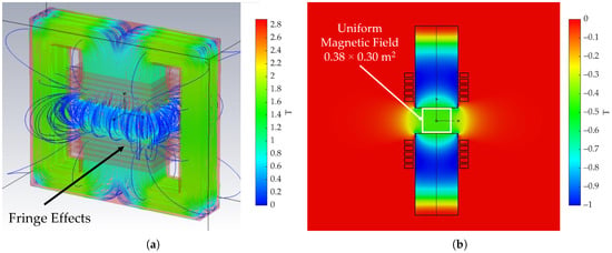
Figure 4.
Simulation of the MNP17 electromagnet performed in CST Studio Suite® to evaluate the uniformity of the produced magnetic field. (a) Magnetic field flux streamlines of the simulated electromagnet, the field intensity in the air gap center is roughly 0.45 T. Fringe fields are here visible. (b) Magnetic field flux contour plot of the vertical component (v direction) on the v-w plane, highlighting the area in which the intensity is uniform.
2.2. Measurement Procedure
To simulate different experimental conditions, two custom motor holders (Figure 5) were designed and 3D printed:
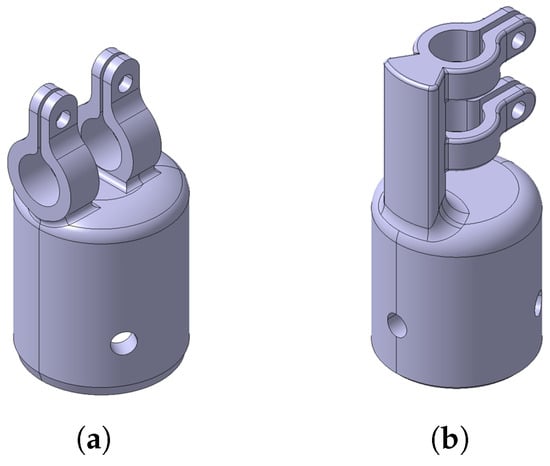
Figure 5.
Motor holder geometries designed and 3D printed for the test. (a) Transversal configuration. (b) Axial configuration.
- Transversal: designed to characterize the mechanical torque of the motor, with the motor axis of rotation kept perpendicular to that of the goniometer (Figure 5a).
- Axial: designed to characterize the internal permanent magnet of the motor, with the motor axis of rotation kept parallel to that of the goniometer (Figure 5b).
To obtain a reliable dataset, 10 motors were tested under different configuration, defined as combinations of the motor holder configuration and motor state (ON/OFF). The measurement campaign was structured as follows: the magnetic field intensity was varied statically from 0 T (for calibration) up to 0.45 T, depending on the case study. For each field intensity, torque and angular speed were recorded over a complete revolution of the goniometer, starting at 0° (motor axis horizontal as represented in Figure 2) with increments of 15°. Goniometer rotation modifies the orientation of the motor axis with respect to the applied magnetic field. Data were acquired under the conditions summarized in Table 3.

Table 3.
Test conditions during the measurement campaign.
Figure 6 illustrates the methods adopted for measuring the motor angular speed. Measurements were performed using an optical speedometer and a lightweight plastic cylinder with a reflective band attached to the motor shaft (Figure 6a). This configuration enabled accurate measurements while minimizing additional loads on the shaft. The optical speedometer, however, provided only absolute values of angular speed, as it always returned positive values regardless of whether the motor rotated clockwise or counterclockwise. To overcome this limitation, an alternative method was implemented during selected tests: a propeller was mounted on the motor shaft so that the airflow it generated allowed identification of the rotation direction and detection of possible angular speed reversals (Figure 6b).
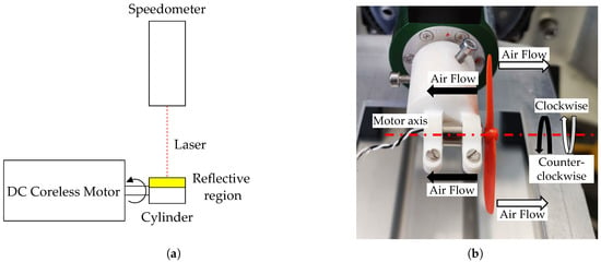
Figure 6.
Motor angular speed measurement methods. (a) Schematic representation of the setup adopted for shaft angular speed measurement. (b) Method adopted to determine the motor’s rotation direction.
The raw data were post-processed by computing the time-averaged values of torque and angular speed over the entire recording duration, for each combination of orientation angle across the full rotation. To account for systematic errors and to suppress torque disturbances arising from static imbalances, the torque calibration curve obtained at 0 T was subtracted from all measurements.
2.3. Theoretical Framework
Considering the internal structure of a brushed DC motor, the measured torque is expected to arise from the interaction between the external magnetic field and the internal permanent magnet (PM), which can be reliably modelled as a magnetic dipole. In a brushed motor, the PM acts as the stator element and its magnetic dipole moment is oriented perpendicular to the motor axis, as determined by the constructive design of the stator assembly. For a detailed description of the magnetic field configuration in brushed DC motors, see, e.g., [31]. The subsequent analysis assumes that the permanent-magnet dipole moment of the motor remains unchanged under increasing magnetic-field strengths and does not undergo any irreversible alteration of its magnetization state.
The interaction between an external magnetic field and the field generated by a magnetic dipole produces a torque vector according to the well-known relation [32]:
where is the magnetic dipole moment, is the external magnetic field, is the angle between them, and is the unit vector in the direction of the torque.
Assuming that the PM dipole is oriented perpendicular to the motor axis, the geometric representation of the two test configurations obtained using the axial and transversal motor holders (Figure 5) is shown in Figure 7. The figure illustrates the reference frame conventions adopted for the analysis of the experimental results.
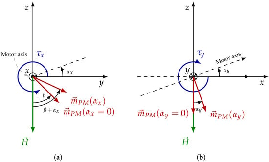
Figure 7.
Reference frames employed for torque analysis. (a) Axial configuration: motor rotation around the x-axis by angle , yielding the magnetic dipole moment . (b) Transversal configuration: motor rotation around the y-axis by angle , yielding the magnetic dipole z-component .
In the test performed with the axial motor holder (Figure 7a), the motor axis coincides with the x-axis, and the motor is rigidly rotated about x by an angle , controlled by the goniometer. The PM magnetic dipole moment lies in the -plane and forms an angle with the external magnetic field , which is directed along the negative z-axis. The angle is defined as positive when measured counter-clockwise from the axis. According to this convention, the magnetic moment and the magnetic field can be written in components as:
From Equation (2), it can be observed that since the PM is oriented perpendicular to the motor axis, which coincides with the x-axis, the x component of the magnetic moment is zero. When the motor rotates by an angle around the x-axis, the magnetic dipole moment undergoes the same rotation. Consequently, forms an angle of with the magnetic field vector .
The torque acting on the motor, along the x-axis, is then obtained as:
Equation (3) shows that the torque depends on the sum of the initial misalignment angle between and and the rotation angle imposed by the goniometer. In the nominal case, , the torque reduces to (1), as expected when both the dipole and the field are fixed. The negative sign arises from the fact that is oriented along the direction.
In the transversal holder configuration (Figure 7b), the motor is rotated about the y-axis instead of the x-axis. When viewed in the -plane, the projection of the magnetic moment onto this plane corresponds to its z-component and the external field lie along the z-axis. In this case, the motor holder is rigidly rotated around the y-axis by an angle , controlled by the goniometer. Initially, the motor axis is aligned with the y-axis, and the magnetic moment in the -plane is parallel to the magnetic field vector . Consequently, the torque acting on the motor can be expressed as:
Equation (4) shows that the torque about the y-axis vanishes when and , as the magnetic dipole moment is aligned with the magnetic field.
To characterize the equilibrium conditions for the transversal configuration, the magnetic potential energy associated with the dipole-field interaction can be expressed as [32]:
which highlights that equilibrium configurations correspond to extrema of the magnetic potential energy: a stable equilibrium occurs at (minimum energy), while an unstable equilibrium arises at (maximum energy). As the motor rotates within the external field, the torque reaches its maximum and minimum values at and , respectively.
Before implementing the experimental apparatus, a preliminary test was conducted in which the behaviour of a motor manually placed in the magnetic field was observed. As shown in Figure 8, the motor spontaneously aligns along a specific direction, tending to reach an orientation of approximately with respect to the magnetic field streamlines, contrary to the expectations based on the previous analysis. Based on the theoretical representation, the expected stable equilibrium orientation should have been , corresponding to the alignment of the PM dipole z-component with the external field , for which and the torque in Equation (4) vanishes.
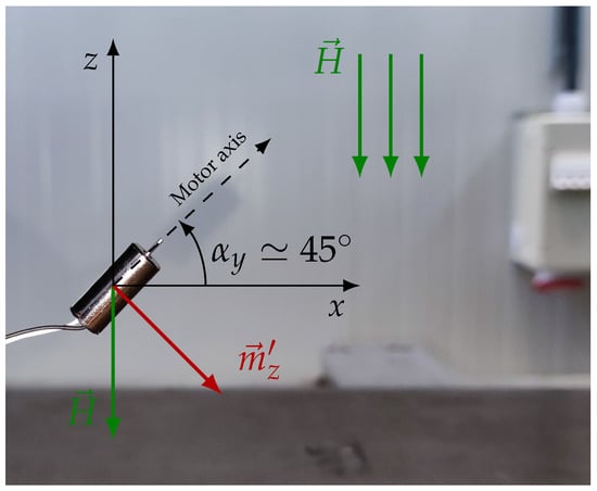
Figure 8.
Motor unconstrained and manually placed in the external magnetic field in its stable position at .
The experimentally observed equilibrium at suggests the presence of additional effects, most likely due to the magnetization of ferromagnetic components within the motor assembly. The phenomenon is illustrated in Figure 9, where a small positive rotation of the DC motor with respect to the magnetic field lines causes the external magnetic field to magnetize the motor housing. The housing, acting as a ferromagnetic path, channels part of the field and rapidly reaches magnetic saturation.
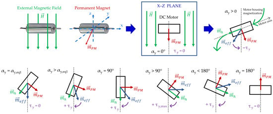
Figure 9.
Graphical and qualitative representation of the torque trends of a DC motor immersed in a uniform external magnetic field, showing the effect of the permanent magnet dipole and the dipole resulting from the magnetization of the motor housing.
In this configuration, the motor exhibits two magnetic dipoles: , associated with the permanent magnet, and , generated by the magnetization of the motor housing. Their vector sum defines the effective magnetic dipole of the motor, . As the rotation continues, at the dipole aligns with the external magnetic field, producing zero torque along the y-axis and explaining the equilibrium point shown in Figure 8. For , the torque along the y-axis changes sign and therefore direction, reaching its maximum magnitude near . Beyond this point, the torque decreases and becomes zero at . In this condition, the contribution of the housing is cancelled, as the external magnetic field no longer has a preferential direction to channel through the material. Consequently, the motor’s magnetic dipole coincides with that of the internal PM.
Therefore, as the motor rotates within the external magnetic field, a new magnetic dipole moment is induced. This induced dipole is zero when the motor is in the horizontal configuration and reaches its maximum when the motor is in the vertical configuration. The resulting effective dipole , obtained as the sum of the induced dipole and the PM dipole, leads to an expected torque profile that follows the behaviour of the effective dipole rather than that of the PM alone.
The qualitative behaviour illustrated in Figure 9 can be modelled using a linear analytical model that computes the housing magnetic moment induced by the applied field through effective demagnetizing factors [33]. In this model the external field is projected into the housing frame (denoted hereafter with a prime ′), the component-wise magnetization is obtained using effective demagnetizing factors along the principal axes, and the total magnetic moment is the volume integral of the magnetization. The model is valid in the linear (non-saturated) regime. For large fields a non-linear relation or FEM validation should be used.
Assuming for the housing a diagonal (principal-axis) demagnetization tensor and an isotropic susceptibility in the linear regime, the component-wise magnetization is:
where is the magnetic permeability of free space. The total induced dipole moment is then:
where V is the magnetizable volume of the housing. This linear model is valid while remains below the saturation magnetization . Combining Equation (6) with Equation (7), the housing magnetic moment in the housing reference frame can be written as:
The housing magnetic moment in the fixed reference frame becomes:
The torque acting on the motor housing can be expressed as:
The torque measured with the transversal motor holder is thus given by the sum of Equations (4) and (10):
Figure 10 illustrates the expected torque behaviour predicted by Equation (11) as a function of for increasing values of the applied magnetic field H. These trends were obtained by setting the magnetic susceptibility to , and by approximating the motor housing as a cylinder with volume m3, axial demagnetizing factor , and transversal demagnetizing factor .
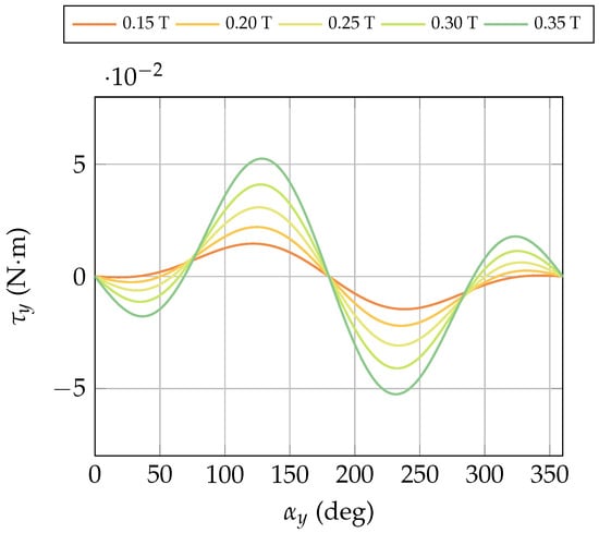
Figure 10.
Expected torque behaviour predicted by Equation (11) as a function of for increasing values of the applied magnetic field.
3. Results
3.1. Transversal Torque Measurements
Figure 11 summarizes the experimental tests performed on 10 motors. The tests include transversal motor holder configuration and both motor ON/OFF conditions, under external magnetic fields ranging from 0 to 0.4 T. The markers represent the mean torque values computed across all tested magnetic field intensities (from 0 to 0.4 T) for each sampled angular position, taken every 15°. The continuous lines represent spline interpolation of these averaged data. Overall, the measured torque oscillates as a function of the shaft angle under the applied constant magnetic field, with magnitudes generally confined within N·m.
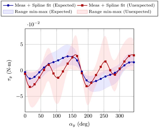
Figure 11.
Torque as a function of the shaft angle under external magnetic fields. The blue curve represents the expected behaviour, showing the raw mean torque values across all magnetic fields applied (markers), the spline interpolation of the mean values (solid line), and the corresponding min–max torque range (shaded area). The red curve represents the unexpected behaviour, following the same graphical conventions.
The first notable observation in Figure 11 is the presence of two distinct torque response patterns: an expected response, consistent with the theoretical framework presented in Section 2.3 (Equation (11) and Figure 10), and an unexpected response. These occurred in approximately 60% and 40% of the tests, respectively.
The expected response in Figure 11 reflects the analysis made in Section 2.3, as illustrated in Figure 9. The distinctions between the two different behaviours can be attributed to the unexpected mobility of the internal PM. In brushed DC motors, the PM serves as the stator and is therefore expected to remain fixed relative to the motor housing. For the tested miniature brushed DC motors, however, the internal PM exhibited a certain degree of mobility. This effect was evident in the 40% of the tested motors, suggesting that it may arise from the limited constructive robustness of low-cost designs.
In the case of a completely free internal PM, referred to as the unexpected behaviour, the phenomenon is shown in Figure 12. Initially, the magnetic moment rapidly aligns with the external magnetic field (first rotation). Consequently, the resulting torque behaviour is identical to that of the blocked case (Figure 9) up to . When , undergoes a second rotation to minimize the magnetic potential energy [32], as defined in Equation (5), thereby driving the system toward a more stable equilibrium configuration. This rotation changes the effective motor dipole direction, with a consequent inversion of the torque sign. After this, a second equilibrium point is reached at , then the torque changes sign again and, in the end, for it reaches a null value. This second scenario is coherent with the torque curves of the unexpected behaviour in Figure 11, making it reasonable to assume that motors have a partially rotating permanent magnet. Therefore, the mobility of the motor’s internal permanent magnet is envisioned to be the primary causes of the different observed behaviours.
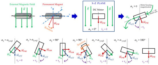
Figure 12.
Graphical and qualitative representation of torque trends of a DC motor immersed in a uniform external magnetic field in the case of the internal permanent magnet completely free to rotate.
Although these behaviours in Figure 11, differ in several aspects, they share some common features: they exhibit the same trend with respect to the magnetic field intensity, they present an unstable equilibrium point at 180° and they display an antisymmetric profile about this point. The main differences between the two behaviours concern the number of nodes (intersections with the horizontal axis) and the number of peak-to-peak oscillations (derivative sign changes).
From the overall results presented in Figure 11, it is possible to analyse the variability of the measured data among different motors, providing a general indication of the absolute torque levels. However, by focusing on a specific field strength, the mean trend and the dispersion across the tested motors can be more clearly appreciated. Figure 13 and Figure 14 illustrate these aspects for magnetic field intensities of 0.2 T and 0.3 T, respectively. In the unexpected behaviour group the torque values present larger fluctuations with respect to the angle, with several sign changes and higher standard deviations, especially around 45– and again in the region 225–. This indicates a less consistent torque response under the same magnetic conditions. On the other hand, the expected behaviour group exhibits smoother and more repeatable trends, with lower standard deviations and torque values that follow a more regular angular dependence. This difference highlights the presence of two distinct operating regimes: one where the motors generate stable and predictable torque, and another where the response is more irregular and scattered.
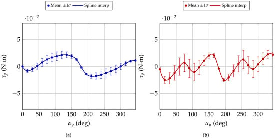
Figure 13.
Torque comparison among different motors at a magnetic field intensity of 0.2 T. The markers indicate the mean torque values, the continuous line shows the spline interpolation, and the error bars represent the standard deviation across repeated measurements. (a) corresponds to the expected behaviour. (b) corresponds to the unexpected behaviour.
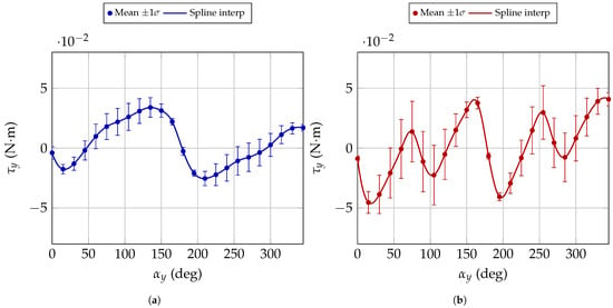
Figure 14.
Torque comparison among different motors at a magnetic field intensity of 0.3 T. The markers indicate the mean torque values, the continuous line shows the spline interpolation, and the error bars represent the standard deviation across repeated measurements. (a) corresponds to the expected behaviour. (b) the corresponds to the unexpected behaviour.
To give a more in depth detail, a motor exhibiting the expected behaviour and another showing an unexpected response, both with transversal holder, were selected to show the torque as a function of for different applied magnetic fields. The corresponding results, obtained with the motors switched OFF, are presented in Figure 15. In both cases, the markers represent the mean torque values averaged over the acquisition period of the torque sensor, corresponding to the measured data, while the continuous line denotes the spline interpolation. From both behaviours, it can be observed that the amplitude increases with the field intensity.
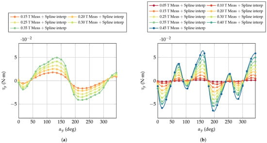
Figure 15.
Torque measurements as a function of the motor axis orientation with respect to the magnetic field when the motors are switched off. Markers represent the measured data while solid lines correspond to the spline interpolations. (a) Expected behaviour. (b) Unexpected behaviour.
Comparison Between Motor ON/OFF
The comparison between the motor ON/OFF conditions provides insight into the influence of motor activation on the measured torque behaviour. As shown in Figure 16, for both the motor behaviours, the overall torque profile remains approximately sinusoidal in both cases, indicating that the intrinsic magnetic interaction dominates the response. However, the activation of the motor slightly modifies the torque amplitude, as evidenced by a reduction in both the maximum and minimum torque values (from 0.0494 N·m to 0.0372 N·m and from −0.0409 N·m to −0.0270 N·m, respectively). These variations suggest the presence of additional dynamic effects or partial magnetic coupling induced by the motor current. The leading cause is likely related to the magnetic field generated by the windings while the motor is operating. This additional component modifies the overall electromagnetic configuration of the motor, altering its effective dipole and thereby interacting with both the motor cover and the permanent magnet. Moreover, an increase in the external field intensity generally results in higher current absorption, which in turn amplifies the contribution of the winding field.
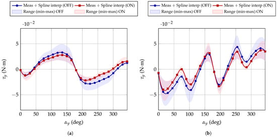
Figure 16.
Comparison between motor OFF and motor ON conditions. Markers represent the measured data, solid lines the corresponding spline interpolations, and the shaded areas indicate the torque range observed within the magnetic field interval 0.15–0.35 T. (a) Expected behaviour, (b) Unexpected behaviour.
3.2. Axial Torque Measurements
After observing the correlation between the displacement of the internal PM and the resulting torque, the axial motor holder was designed to directly detect these effects. In this configuration, secondary effects are negligible. Only the interaction between the external magnetic field and the motor PM is expected to play a role. This is because the motor shaft is parallel to the goniometer’s rotation axis (Figure 7a), and therefore the induced dipole moment due to this orientation relative to the vertical magnetic field is negligible. This effect is also illustrated in Figure 9 and Figure 12, for the case . As a result, the contribution of the motor cover is removed by the axial holder, while keeping the motors switched off prevents additional disturbances. Figure 17 shows the measured torque as a function of the motor axis orientation within magnetic fields ranging from 0.05 T to 0.35 T. According to the theoretical relation given by Equation (3), the torque originates solely from the interaction between the internal permanent magnet and the external magnetic field. Each curve in Figure 17 was fitted with a sinusoidal function to evaluate the deviation from the ideal sinusoidal behaviour expected for a fixed dipole. The fitting model adopted was:
where is the offset, the amplitude, the phase shift, and deg−1 the fundamental frequency corresponding to one full revolution. The fitting procedure was performed in MATLAB® 2024b using the fit function with the sinusoidal model in Equation (12). For each magnetic field intensity, the fitting parameters and related statistical metrics were extracted, including the coefficient of determination (), adjusted , and the root-mean-square error (RMSE). Table 4 summarizes the obtained results.
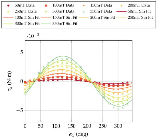
Figure 17.
Measured torque as a function of the motor axis orientation with respect to the magnetic field (axial configuration, motor switched off).

Table 4.
Results of the sinusoidal fitting of the axial torque measurements for different magnetic field intensities.
The estimated magnetic moment , obtained from the fitted torque amplitudes, was calculated according to:
In the left panel of Figure 18, the estimated magnetic moment is shown as a function of the magnetic field. The trend resamble the characteristic behavior of a magnetic dipole with a weakly hysteretic response [32]. This suggests that a small degree of magnetization may occur under increasing field strength. In the right panel of Figure 18, the fitted torque amplitudes are plotted versus the magnetic field intensity. A clear proportional increase with is observed, confirming the linear dependence predicted by Equation (3) and supporting the hypothesis that the torque arises from the dipole–field interaction in the axial configuration. Overall, the sinusoidal fitting and subsequent analysis validate that the internal permanent magnet maintains a predominantly fixed orientation relative to the rotor axis.
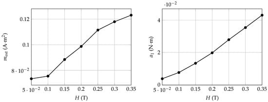
Figure 18.
Estimated magnetic moment (left) and torque amplitude (right) as functions of the magnetic field intensity.
To verify whether the unexpected torque behaviour originated from a mobility of the internal PM, a dedicated test was performed. Under the hypothesis that the internal PM is completely free to rotate within the housing, its magnetic dipole would continuously align with the external field, leading to a net torque close to zero (apart from minor contributions due to the magnetization of the ferromagnetic motor cover). To experimentally validate this assumption, one motor was deliberately modified by mechanically detaching the internal PM from the rotor cover, allowing it to rotate freely. The resulting torque responses were compared with those of nominally identical, unmodified motors under the same magnetic field intensity.
Figure 19 shows the measured torque as a function of the motor axis orientation for four different motors tested in a 0.35 T magnetic field using the axial holder configuration. For this comparison, the sinusoids were aligned with each other by imposing that the initial phase shift in Equation (3) is zero. The curve corresponding to motor M4 represents the case with an intentionally free-to-rotate permanent magnet. Motors M1 and M2 correspond to configurations with a fixed magnet, exhibiting the expected sinusoidal behaviour consistent with the dipole–field interaction. Conversely, motor M3 shows an intermediate response, characterized by a noticeable reduction in torque amplitude and a phase distortion approaching that of M4.
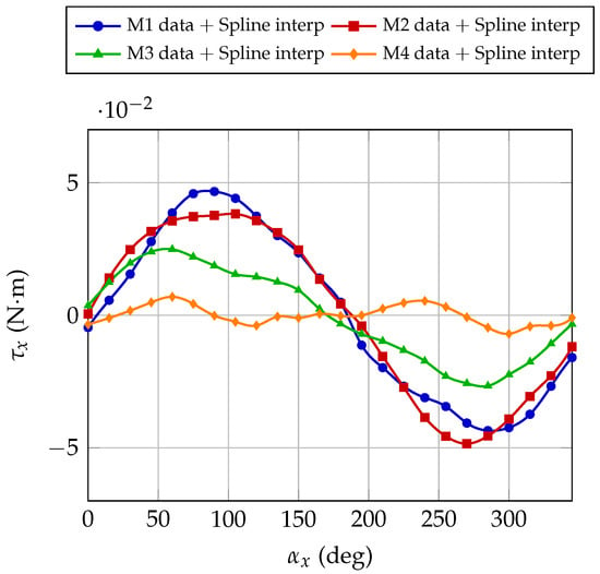
Figure 19.
Comparison between different motors supported by an axial motor holder immersed in a magnetic field intensity of 350 mT as a function of the rotation around the motor’s principal axis. Markers represent measured data and the continuous line is a spline fit.
These results confirm that deviations from the ideal sinusoidal response can be attributed to partial mobility of the internal magnet. When the magnet is fully constrained, the torque follows the expected sinusoidal trend in Equation (3). When the magnet is free (or partially decoupled) its dipole tends to align with the external field, resulting in a smaller effective torque. This comparison provides strong experimental evidence that the unexpected torque anomalies observed in certain motors are due to internal mechanical freedom of the permanent magnet.
3.3. Angular Speed Measurements
The motor angular speed was measured using the transversal motor holder configuration. Figure 20 reports the measured absolute value of the angular speed as a function of the motor axis orientation, for field intensities ranging from 0 to 0.25 T. The black dotted line in Figure 20 indicates the nominal speed of RPM, corresponding to the rated voltage and zero magnetic field. Experimental data are shown as markers, while the continuous lines represent spline interpolations. The results demonstrate a clear dependence of the rotational speed on both the orientation of the motor axis and the magnetic field intensity. An increase of approximately 4.5% was observed at 0.05 T (corresponding to RPM), reaching up to about 22% at 0.25 T ( RPM).
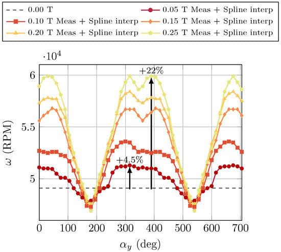
Figure 20.
Measured angular speed as a function of the motor axis orientation with respect to the magnetic field. The markers represent the experimental data while the solid lines correspond to the spline interpolations.
The measured values are consistent with those reported in previous studies [34]. Specifically, the angular speed of a single-pole DC motor can be expressed as in Equation (14):
where k is a constant determined by the motor’s construction parameters, is the back electromotive force, and is the magnetic flux of the winding. The flux can be significantly influenced by both the external magnetic field intensity and the orientation of the motor.
Motors were generally affected by rotation direction flips when the motor axis was oriented at approximately 180° with respect to the magnetic field lines and its extent increased with the magnetic field intensity. In most cases, the change in direction was preceded by a motor stall, i.e., the rotor became static and was unable to resume autonomous motion even when subjected to external mechanical perturbations. It is important to note that no specific threshold of magnetic field intensity was identified for the occurrence of these direction inversions. Different motors exhibited rotation flips at different magnetic field values, and in some cases no direction inversions or stalls were observed at all, even under exposure to 0.4 T.
Figure 21 shows the drawing of the cross-section of a motor. Under standard conditions, with a null external magnetic field, the motor torque and the resulting angular velocity depend on the angle between the winding field and that of the PM. In the experimental conditions of this study, however, in addition to the contribution of the PM, there are contributions from the external magnetic field and from the dipole field generated by the magnetization of the motor cover. Therefore, depending on the angle between the winding field and the resulting magnetic field (i.e., the vector sum of the different magnetic contributions), a torque and an angular velocity are generated, which may experience flips from clockwise to counter-clockwise rotation.
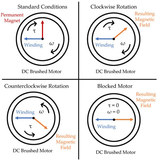
Figure 21.
Schematic explanation of the direction, function of the angle between the resulting magnetic field and the field generated by the winding. Standard condition represents the nominal functioning outside the magnetic field.
If this angle is 0° or 180°, the motor stalls due to the null sine term in the torque expression. Therefore, any factor that may influence the orientation of the resulting magnetic field vector can affect the rotational direction. In addition, the presence of a movable permanent magnet may further amplify this behaviour.
3.4. Electrical Current Consumption
The final aspect analysed in the test campaign was the electrical current consumption of the motors. As shown in Figure 22, for a brand-new motor without magnetic field and without a propeller, the measured current absorption was approximately 0.05 A. When a propeller was mounted on the same motor, the current increased to A. In contrast, motors that had previously been exposed to a magnetic field of T showed a higher current demand under the same conditions. At 0 T, these motors absorbed A without a propeller and A with a propeller attached.
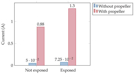
Figure 22.
Comparison of the electrical current consumption of motors with and without a propeller, for both new (not exposed) and previously exposed ( T) motors.
Overall, prior exposure to a strong magnetic field resulted in an increase of approximately in current consumption compared to new, unexposed motors operating under identical test conditions. Notably, such increase in current consumption implies a proportional rise in Joule heating within the battery pack, potentially exacerbating thermal stresses and reducing both endurance and safety in battery-powered UAVs. This systemic effect highlights the relevance of incorporating advanced battery thermal management strategies, as recently investigated in [35].
In the standard condition shown in Figure 21, the angle between the permanent magnet dipole and that of the winding is around 90° to maximize the output torque in Equation (1). However, if this angle changes, due to internal permanent magnet rotations and magnetization effects, a higher current is required to obtain the same output.
4. Discussion
To summarize the analysis and results presented in Section 3, the main phenomena that explain the observed behaviours are discussed below.
- Motor cover magnetization. The ferromagnetic motor cover can channel external magnetic field lines along its axis, resulting in two possible magnetization directions. Although this contribution should be limited by the cover’s saturation properties, it is not negligible and is likely the cause of the unstable equilibrium observed at in all torque measurements. At this orientation, small perturbations can force the field lines into opposite directions, generating divergent torque contributions with opposite signs and leading to instability.
- Internal permanent magnet mobility. In some motors, the internal permanent magnet exhibited full or partial rotations during re-orientation within the external magnetic field, with different levels of friction. This behaviour is in contrast with the correct functioning of a brushed DC motor, where the internal permanent magnet (stator) should remain fixed relative to the brushes and housing. Motors with a movable internal permanent magnet tend to experience higher absolute torques compared to those with a blocked magnet, as the internal dipole tends to minimize the magnetic potential energy by aligning with the external field, thereby increasing the torque component along the y-axis.
- Hysteretic material properties. High external magnetic field intensities may exceed the coercivity of the internal permanent magnet, altering its magnetization state in terms of saturation remanence and dipole direction. Consequently, both the magnitude and direction of the internal dipole can change, influencing the torque vector. This effect often occurs in combination with internal magnet mobility, further contributing to the modification of torque curves.
- Magnetic field generated by the winding. When the motor is switched on, the current flowing through the winding produces an additional magnetic field that interacts with both the cover and the internal permanent magnet. This alters the overall electromagnetic configuration of the motor, effectively modifying its equivalent dipole. Furthermore, higher external field intensities generally increase current absorption, which amplifies the winding’s contribution.
- Increase in current consumption. Prior exposure to a magnetic field can lead to a 40–50% increase in current consumption. In the present study, the analysis was limited to the mechanical and electrical effects observed during and after field exposure, and no post-exposure magnetic characterization of the permanent magnets was performed. To address this limitation, future work will include extracting the stator permanent magnets and measuring their pre- and post-exposure magnetic hysteresis (B-H) curves. This will enable us to determine whether the observed effects arise from irreversible magnetic changes or from mechanical shifts of the magnets within the housing.
5. Conclusions
The overall objective of this work was to characterize the behaviour of a robotic actuation system in a high-intensity magnetic field environment, such as that foreseen for an indoor airship intended for underground inspections at CERN facilities. The proposed methodology and measurement strategy were validated by assessing the performance of miniature brushed DC coreless motors, which, although low-cost devices, provided a suitable case study. The approach is easily extendable and applicable to other types of electromagnetic motors.
The obtained results highlight the overall ability of the analysed motors to operate in external magnetic fields up to 0.4 T. The measured absolute mechanical torque values along an axis orthogonal to the motor shaft remained below 0.07 N·m. Nevertheless, different torque behaviours were observed among motors of the same make and model. These discrepancies are likely related to poor manufacturing quality, where some motors exhibit a partially movable internal permanent magnet, thus allowing rotations that modify its relative position with respect to the brushes. It is expected that motors of more robust construction may not exhibit the effect of internal permanent magnet mobility, thereby reducing part of the observed anomalies. Further experiments are therefore required to fully understand the behaviour of robotic actuators in magnetic environments, expanding the investigation to different motor types, including PMDC iron-core motors in addition to the PMDC coreless motors already examined, as well as brushless DC (BLDC) motors, with particular attention to the choice of encoders and potential shielding solutions.
The analytical model, which accounts only for the permanent magnet and the magnetization of the motor housing, successfully predicted the qualitative torque trend as a function of the motor’s rotation in the external field. However, it also revealed inherent limitations, as it does not capture additional effects such as permanent-magnet remagnetization due to hysteretic behavior or the magnetic field generated by the windings. To overcome these limitations, FEM-based numerical simulations can provide a more complete prediction of the mechanical disturbances experienced by DC motors in external magnetic fields, as a function of both motor orientation and field intensity.
During the experiments, variations in angular speed and occasional flipping events were also observed. These phenomena appear to arise from the strong external magnetic field altering the internal field configuration responsible for generating torque between the stator and rotor, which in turn can trigger the flips detected using the mounted propeller. However, further investigation is required, as the flipping behavior was not consistent across all motors and occurred only at field strengths above 0.4 T.
In conclusion, this work provides an important contribution toward understanding magnetic disturbances on electromagnetic motors. Such knowledge is valuable for the design and control of robotic platforms operating in harsh magnetic environments. In particular, control systems of robotic platforms actuated by electromagnetic motors should explicitly account for these disturbances within their dynamic models, in order to counteract them and ensure platform stability.
Author Contributions
Conceptualization, L.B.; methodology, L.B.; software, L.B. and F.M.; validation, L.B. and F.M.; formal analysis, L.B. and F.M.; investigation, L.B. and F.M.; resources, L.B. and F.M.; data curation, L.B. and F.M.; writing—original draft preparation, L.B.; writing—review and editing, F.M. and P.F.S.; visualization, F.M.; supervision, P.F.S.; project administration, C.G. and F.C. All authors have read and agreed to the published version of the manuscript.
Funding
This research received no external funding.
Data Availability Statement
The data supporting the findings of this study are available in the following Zenodo record: https://doi.org/10.5281/zenodo.17222821.
Acknowledgments
The authors would like to acknowledge the European Organization for Nuclear Research (CERN) for providing the necessary facilities and support for this research. Special thanks to the teams in the Experimental Physics Department for their technical assistance. The authors used ChatGPT version 5.0 (OpenAI) exclusively for English grammar correction and language refinement. No content, analysis, data interpretation, or research ideas were generated by the tool. All scientific content and results are entirely the authors’ own work.
Conflicts of Interest
The authors declare no conflicts of interest.
References
- Trevelyan, J.; Hamel, W.R.; Kang, S.C. Robotics in hazardous applications. In Springer Handbook of Robotics; Springer: Berlin/Heidelberg, Germany, 2016; pp. 1521–1548. [Google Scholar]
- Wong, C.; Yang, E.; Yan, X.T.; Gu, D. An overview of robotics and autonomous systems for harsh environments. In Proceedings of the 2017 23rd International Conference on Automation and Computing (ICAC), Huddersfield, UK, 7–8 September 2017; pp. 1–6. [Google Scholar]
- Shukla, A.; Karki, H. A review of robotics in onshore oil-gas industry. In Proceedings of the 2013 IEEE International Conference on Mechatronics and Automation, Takamatsu, Japan, 4–7 August 2013; IEEE: Piscataway, NJ, USA, 2013; pp. 1153–1160. [Google Scholar]
- Chitikena, H.; Sanfilippo, F.; Ma, S. Robotics in search and rescue (sar) operations: An ethical and design perspective framework for response phase. Appl. Sci. 2023, 13, 1800. [Google Scholar] [CrossRef]
- Marshall, J.A.; Bonchis, A.; Nebot, E.; Scheding, S. Robotics in mining. In Springer Handbook of Robotics; Springer: Berlin/Heidelberg, Germany, 2016; pp. 1549–1576. [Google Scholar]
- Gao, Y.; Chien, S. Review on space robotics: Toward top-level science through space exploration. Sci. Robot. 2017, 2, eaan5074. [Google Scholar] [CrossRef]
- Tsitsimpelis, I.; Taylor, C.J.; Lennox, B.; Joyce, M.J. A review of ground-based robotic systems for the characterization of nuclear environments. Prog. Nucl. Energy 2019, 111, 109–124. [Google Scholar] [CrossRef]
- Bogue, R. Underwater robots: A review of technologies and applications. Ind. Robot. Int. J. 2015, 42, 186–191. [Google Scholar] [CrossRef]
- Campbell, D. The physics of the international thermonuclear experimental reactor FEAT. Phys. Plasmas 2001, 8, 2041–2049. [Google Scholar] [CrossRef]
- Holtkamp, N.; ITER Project Team. An overview of the ITER project. Fusion Eng. Des. 2007, 82, 427–434. [Google Scholar] [CrossRef]
- Claessens, M. ITER: The Giant Fusion Reactor; Springer: Cham, Switzerland, 2020. [Google Scholar]
- Evans, L. The large hadron collider. New J. Phys. 2007, 9, 335. [Google Scholar] [CrossRef]
- Aad, G.; Anduaga, X.S.; Antonelli, S.; Bendel, M.; Breiler, B.; Castrovillari, F.; Civera, J.; Del Prete, T.; Dova, M.T.; Duffin, S.; et al. The ATLAS experiment at the CERN large hadron collider. J. Instrum. 2008, 3, S08003. [Google Scholar] [CrossRef]
- Aamodt, K.; Quintana, A.A.; Achenbach, R.; Acounis, S.; Adamová, D.; Adler, C.; Aggarwal, M.; Agnese, F.; Rinella, G.A.; Ahammed, Z.; et al. The ALICE experiment at the CERN LHC. J. Instrum. 2008, 3, S08002. [Google Scholar] [CrossRef]
- CMS Collaboration; Chatrchyan, S.; Hmayakyan, G.; Khachatryan, V.; Sirunyan, A.M.; Adam, W.; Bauer, T.; Bergauer, T.; Bergauer, H.; Dragicevic, M.; et al. The CMS experiment at the CERN LHC. J. Instrum. 2008, 3, 1–334. [Google Scholar]
- Collaboration, L. LHCb detector performance. Int. J. Mod. Phys. A 2015, 30, 1530022. [Google Scholar] [CrossRef]
- Aleksa, M.; Bergsma, F.; Giudici, P.A.; Kehrli, A.; Losasso, M.; Pons, X.; Sandaker, H.; Miyagawa, P.; Snow, S.; Hart, J.; et al. Measurement of the ATLAS solenoid magnetic field. J. Instrum. 2008, 3, P04003. [Google Scholar] [CrossRef]
- Thome, R.J.; Central, I.J.; Teams, H. Design & development of the ITER magnet system. Cryogenics 1994, 34, 39–46. [Google Scholar] [CrossRef]
- Aglieri Rinella, G.; Aleksa, M.; Amatriain, A.; Alfiero, D.; Alvarez Feito, D.; Andorno, M.; Angeletti, M.; Antoszczuk, P.D.; Arena, M.C.; Aretio Zarate, F.; et al. Strategic R&D Programme on Technologies for Future Experiments—Annual Report 2024; Technical Report; CERN: Geneva, Switzerland, 2025. [Google Scholar]
- Mazzei, F.; Teofili, L.; Curti, F.; Gargiulo, C. Mission analysis, dynamics and robust control of an indoor blimp in a CERN detector magnetic environment. Front. Robot. AI 2023, 10, 1238081. [Google Scholar] [CrossRef]
- La Scalea, R.; Rodrigues, M.; Osorio, D.P.M.; Lima, C.; Souza, R.D.; Alves, H.; Branco, K.C. Opportunities for autonomous UAV in harsh environments. In Proceedings of the 2019 16th International Symposium on Wireless Communication Systems (ISWCS), Oulu, Finland, 27–30 August 2019; IEEE: Piscataway, NJ, USA, 2019; pp. 227–232. [Google Scholar]
- Dharmadhikari, M.; Nguyen, H.; Mascarich, F.; Khedekar, N.; Alexis, K. Autonomous cave exploration using aerial robots. In Proceedings of the 2021 International Conference on Unmanned Aircraft Systems (ICUAS), Athens, Greece, 15–18 June 2021; IEEE: Piscataway, NJ, USA, 2021; pp. 942–949. [Google Scholar]
- López Fernández, J.; González, P.; Sanz, R.; Burgard, W. Developing a Low-Cost Autonomous Indoor Blimp. J. Phys. Agents 2009, 3, 43–52. [Google Scholar]
- Mazzei, F.; Burkart, A.; Scaramuzzino, P.F.; Sobotta, F.; Curti, A.; Gargiulo, C. Development of Small Airships for Indoor Exploration and Inspection of the CERN Underground Facilities. In Proceedings of the 12th International Airship Conference, Zeppelinheim, Germany, 25–26 October 2024. [Google Scholar]
- Habib, A.; Mohd Zainuri, M.A.A.; Che, H.S.; Ibrahim, A.A.; Rahim, N.A.; Alaas, Z.M.; Ahmed, M.M.R. A systematic review on current research and developments on coreless axial-flux permanent-magnet machines. IET Electr. Power Appl. 2022, 16, 1095–1116. [Google Scholar] [CrossRef]
- Giernacki, W.; Skwierczyński, M.; Witwicki, W.; Wroński, P.; Kozierski, P. Crazyflie 2.0 quadrotor as a platform for research and education in robotics and control engineering. In Proceedings of the 2017 22nd International Conference on Methods and Models in Automation and Robotics (MMAR), Miedzyzdroje, Poland, 28–31 August 2017; IEEE: Piscataway, NJ, USA, 2017; pp. 37–42. [Google Scholar]
- Yun, J.; St. Aubin, J.; Rathee, S.; Fallone, B. Brushed permanent magnet DC MLC motor operation in an external magnetic field. Med. Phys. 2010, 37, 2131–2134. [Google Scholar] [CrossRef] [PubMed]
- Heggo, M.; Kabbabe, K.; Peesapati, V.; Gardner, R.; Watson, S.; Crowther, W. Operation of aerial inspections vehicles in HVDC environments Part A: Evaluation and mitigation of high electrostatic field impact. J. Phys. Conf. Ser. 2019, 1356, 012009. [Google Scholar] [CrossRef]
- Heggo, M.; Mohammed, A.; Melecio, J.; Kabbabe, K.; Tuohy, P.; Watson, S.; Djurovic, S. Operation of aerial inspections vehicles in HVDC environments Part B: Evaluation and mitigation of magnetic field impact. J. Phys. Conf. Ser. 2019, 1356, 012010. [Google Scholar] [CrossRef]
- Heggo, M.; Mohammed, A.; Melecio, J.; Kabbabe, K.; Tuohy, P.; Watson, S.; Durovic, S. The operation of UAV propulsion motors in the presence of high external magnetic fields. Robotics 2021, 10, 79. [Google Scholar] [CrossRef]
- Hughes, A.; Drury, B. Electric Motors and Drives: Fundamentals, Types and Applications; Newnes: Oxford, UK, 2019. [Google Scholar]
- Griffiths, D.J. Introduction to Electrodynamics, 4th ed.; Cambridge University Press: Cambridge, UK, 2017. [Google Scholar] [CrossRef]
- Prozorov, R.; Kogan, V.G. Effective Demagnetizing Factors of Diamagnetic Samples of Various Shapes. Phys. Rev. Appl. 2018, 10, 14030. [Google Scholar] [CrossRef]
- Singer, S.; Appelbaum, J. Starting characteristics of direct current motors powered by solar cells. IEEE Trans. Energy Convers. 1993, 8, 47–53. [Google Scholar] [CrossRef][Green Version]
- Qi, W.; Yang, J.; Zhang, Z.; Wu, J.; Lan, P.; Xiang, S. Investigation on thermal management of cylindrical lithium-ion batteries based on interwound cooling belt structure. Energy Convers. Manag. 2025, 340, 119962. [Google Scholar] [CrossRef]
Disclaimer/Publisher’s Note: The statements, opinions and data contained in all publications are solely those of the individual author(s) and contributor(s) and not of MDPI and/or the editor(s). MDPI and/or the editor(s) disclaim responsibility for any injury to people or property resulting from any ideas, methods, instructions or products referred to in the content. |
© 2025 by the authors. Licensee MDPI, Basel, Switzerland. This article is an open access article distributed under the terms and conditions of the Creative Commons Attribution (CC BY) license (https://creativecommons.org/licenses/by/4.0/).