Article

Development of an Anthropometric Soft Pneumatic Gripper with Reconfigurable Fingers for Assistive Robotics

Department of Industrial Engineering, University of Florence, Via di Santa Marta 3, 50139 Florence, Italy
*
Author to whom correspondence should be addressed.
Robotics 2025, 14(11), 152; https://doi.org/10.3390/robotics14110152 (registering DOI)
Submission received: 24 September 2025 / Revised: 16 October 2025 / Accepted: 21 October 2025 / Published: 26 October 2025
(This article belongs to the Special Issue Development of Biomedical Robotics)

Abstract

This study presents the development of a prototype anthropomorphic soft robotic gripper intended for applications in rehabilitation and assistive robotics, where safe and adaptive interaction with humans is required. The device consists of three elastomeric fingers, fabricated in TPU via FFF 3D printing and actuated through pneumatic soft actuators that ensure compliant contact with both biological tissue and rigid objects. A custom 3D-printed pneumatic rotary actuator enables finger reconfiguration, thereby extending the range of grasping modalities. The actuation system comprises six 2/2 solenoid valves controlled by an Arduino Uno and integrated into a dedicated pneumatic circuit. Experimental characterization demonstrated a peak grasping force exceeding 17 N on rigid targets, while functional tests in table-picking scenarios confirmed adaptability to objects of varying shapes and sizes. Owing to its anthropomorphic configuration, mechanical compliance, and ease of fabrication and control, the proposed gripper represents a versatile solution for rehabilitation-oriented devices as well as assistive robotic end-effectors in pick-and-place tasks.

1. Introduction

In recent years, robotics has experienced exponential growth in the study and utilization of soft materials. Human–machine interaction is fundamental for several applications: soft materials enable safer, more adaptable, and lifelike interfaces that can better accommodate and respond to the nuances of human movements and intentions. The creation and development of soft materials have allowed for the development of a whole series of new technologies, and have revolutionized several processes. A classic example concerns the field of endoscopy [1], where the use of soft materials has allowed for the development of more effective endoscopes, ensuring results equal to or better than traditional endoscopes, but with a significant increase in patient comfort. PneuNet-type actuators, a specialized subset of soft actuators, excel in providing enhanced compliance, a greater range of force and expansion, simpler control mechanisms, increased durability, and ease of manufacture, setting them apart in the design and functionality of sophisticated robotic systems [2]. They rely on the deformation of the bellows, caused by pressurized air, to perform a controlled movement triggered by the contact between the humps of the bellow [3]. PneuNet actuators are part of a family of soft actuators that also includes foam actuators [4]. Different designs, characterized by alternative bellows configurations [5,6], allow for them to perform various types of movement such as stretching, bending, and rotation. This makes PneuNet actuators very versatile. Soft actuators are often integrated to form robotic grippers, enabling versatile and adaptive grasping of objects with varying shapes and sizes. In this context, recent advancements in soft-robotic grippers have introduced designs utilizing pneumatic multi-chambers made of silicone rubber, significantly enhancing gripping capabilities. This kind of device achieves remarkable performance, including substantial pull-off forces and the ability to handle a wide range of object shapes and weights [7,8]. A widely adopted design seeks to mimic, for obvious reasons, the shape and features of the human hand with varying degrees of fidelity. Robotic hands can be categorized by features such as the number of fingers, the actuation technology, and the ability to change finger positions around the palm. Common solutions include three [9] or four fingers [10,11,12,13], with tendons and bellow actuators [14,15] being the most used technologies.
To enhance the versatility and efficiency of grasping operations, some gripper models have been designed to allow for variations in their overall configuration, making them suitable for a wide range of tasks. This involves adjusting the soft actuators and repositioning them according to the specific needs. The fingers’ movement can be independent [16] or dependent [10] (i.e., the fingers move together generally by means of a single actuation system). Although studies have almost exclusively focused on the realization of hands with fingers characterized by a fixed layout (five fingers—defining an anthropomorphic layout in [17,18] or less [19,20]), recently, increasing interest has been paid towards reconfigurable architectures. In this context, an extensive literature search identified a limited development of pneumatically actuated reconfigurable grippers. A noteworthy example can be found in [21], where the authors present a gripper with three fingers arranged at 120° angles featuring a design where each finger can move radially away from the center of the palm in parallel. Additionally, each finger can rotate around its own axis. All gripper movements (lengthening and shortening, rotation and bending) are obtained by means of six PneuNet actuators. The gripper is reported to approximately generate a 20 N grasping force. While this last solution can show good adaptability, its complexity, involving six different actuators, partially limits the applicability of the presented solution. Moreover, its design limits certain operations, especially the grasping of large cylindrical objects, highlighting the need for a new approach.
To overcome these limitations, this work presents the design, fabrication, and experimental characterization of an anthropomorphic soft robotic gripper prototype intended for rehabilitation and assistive robotics applications, where safe and adaptive human interaction is essential. The proposed device comprises three elastomeric fingers fabricated in thermoplastic polyurethane (TPU) using fused filament fabrication (FFF) 3D printing that ensure compliant contact with both biological tissue and rigid objects. The present paper discusses the development of such a gripper; its main innovations lay in the use of material extrusion 3D printing technology for the fabrication of all the components, with consequent advantages in terms of manufacturing time, customization, and cost reduction. The integration of an integrated rotary pneumatic system allows for fast and efficient reconfiguration and design variations for future applications. The design of the gripper is guided by the application of design for additive manufacturing principles, which has allowed for the use of 3D printing technology for all of the main components. Grippers making use of soft and flexible elements to ensure safe human interaction, but pose challenges in predicting behavior due to the (generally) hyperelastic characteristics of soft materials. To address this aspect, we developed and validated a Finite Element (FE) model of the actuators, featuring a material model suitable for reproducing the behavior of the actual material used in the printing process. This FE model of the actuator helps in the evaluation of the effects caused by changes in the geometry or in the operative conditions, improving the design workflow and the achievable performance.
Overall, the combination of an anthropomorphic layout, mechanical compliance, manufacturability via FFF, and straightforward pneumatic control makes the proposed gripper a versatile candidate both for rehabilitation-oriented devices and as an assistive end-effect in pick-and-place tasks.
The structure of the present article is as follows: Section 2.1 discusses the PneuNet soft actuator integrated into the gripper; Section 2.2 describes the FE approach used to optimize the actuator’s geometry and predict its behavior; Section 2.3 details the design of the finger support; Section 2.4 outlines the design of the pneumatic rotary actuator developed for the reconfiguration mechanism; Section 2.5 explains the fabrication and actuation of the gripper; Section 3.1 presents the results of the grasping force tests, while Section 3.2 discusses the results of the grasping adaptability tests; and finally, Section 4 provides concluding remarks and possible future developments.

2. Design and Fabrication

The design of the gripper focuses on developing a device equipped with three PneuNet-type soft actuators arranged in opposition—mimicking the fingers of the human hand—and capable of executing two distinct grasping modalities. The two configurations, along with the global dimensions, are illustrated in Figure 1.
The configuration with the movable finger in parallel position will henceforth be called “claw”; the other configuration will be called “120°”. The design pursued the goal of a highly versatile gripper, entirely actuated via pneumatics, designed to emulate the size of human hand, and was equipped with features that enable it to grasp objects of various shapes, sizes, and weights. The primary components of the gripper, which will be analyzed in the following sections along with its main structure, are the soft actuators performing the grasping operation and a custom pneumatic rotary actuator designed and developed for the reconfiguration of the gripper itself. The design of the gripper components was realized with a view to manufacturing most of the parts by exploiting the features of FFF (Fused Filament Fabrication) 3D printing. The manufacturing of the components will be discussed in detail in Section 2.4.

2.1. PneuNet-Type Soft Actuator

The development of the pneumatic actuator integrated into the gripper relied on the authors’ previous work [22]; a series of prior studies defined, tested, and validated the parameters and process characteristics for the fabrication of PneuNet-type soft actuators using FFF with TPU (thermoplastic polyurethane) elastomeric material. The design of this actuator consists of a series of chambers in varying numbers and sizes that can be selected according to the specific application. A configuration similar in size and performance to a human finger with a total length of 114.5 mm, a thickness of 1.6 mm, a rectangular section and 12 internal chambers was identified at the end of a design process—discussed in the next section—selected, and is shown in Figure 2; the pneumatic and mechanical interfaces designed for its integration in the gripper allow for an easy replacement of each finger, which could be replaced when damaged or by changing their shape and characteristics to optimize the performance of the gripper for a specific task. An interference connection with the compressed-air-supply tube to ensure tightness up to 3 bar, visible in Figure 2 on the left, was designed.
As reported in Table 1, previous studies by the authors demonstrated that the single finger could exert a blocked force of up to 3.73 N at 3 bar; this metric reflects the actuator’s peak force output under fully constrained conditions, where no displacement occurs and the force is applied directly against a rigid surface.
Other better-performing bellow devices exist in the literature (7 N with an actuating pressure of 2 bar) [19], but the limitations of the performance of our finger stem from the choice of material and manufacturing process. These limitations are known and have been accepted with a view of making a prototype to assess the feasibility of the gripper, being aware that it will be possible to significantly improve its performance in the future, possibly changing the material and/or the manufacturing process.

2.2. Finger Design Process

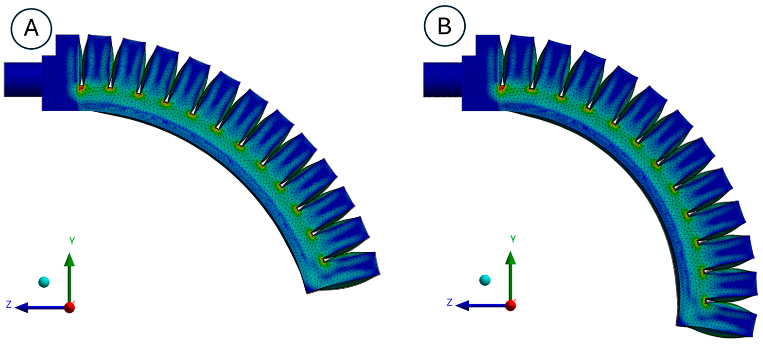
The final configuration of the actuator, as presented in the previous section, was determined through a series of FE simulations conducted on various actuator versions that shared the same fundamental design principles. The design process aimed at a performance maximization, especially the bending angle attained under specific operating conditions. The design process considered changes in the thickness of the actuator’s wall, as well as the number of chambers distributed across its length. Suitable design ranges for such parameters were identified using the authors’ knowledge; a manual, systematic process was applied to guide the exploration of the effects caused by the changes in the parameters. FE analyses were performed according to the setup described in the following section. To demonstrate the positive effects achieved in this phase, an early-stage design and its optimized successor have been compared as examples of the iterative design process. Due to the original chamber dimensions, the first design, depicted in Figure 3A, shows notable limitations, even though it managed to reach a bending angle of 38.8° under 3 bars of pressure. By systematically adjusting geometric parameters, such as wall thickness and chambers geometry, shown in Table 2, a refined design was achieved. Under the same boundary conditions and inflated at the same pressure, the optimized configuration, shown in Figure 3B, demonstrated a bending angle of 50.3°, significantly outperforming the original design.
This comparison serves as an excellent example of how FE analysis is not only a tool for performance evaluation, but also a crucial step in advancing geometric refinement, which eventually results in improved actuator capabilities and alignment with design goals.

2.2.1. Finite Element Analysis

More in detail, the “Static Structural Analysis” module of ANSYS Workbench 2019 R3 (ANSYS Inc., Canonsburg, PA, USA) was used to perform FE simulations. The soft actuators’ 3D model was loaded directly into the “Design Modeler” program for ANSYS within ANSYS for geometry preparation, such as the nomenclature of surfaces later used to apply forces and constraints to them. Previous studies have identified the optimal combination of material parameters to accurately simulate the actuator’s behavior, considering both the constituent material and the fabrication technique. These material parameters are shown in Table 3.
The “large deflection” option was selected due to significant deformations; due to the “large deformation”, a non-linear analysis was performed. A progressive load application ranging from 0.1 s to 1.0 s with a time step of 1 × 10⁻⁴ s was used for improved simulation stability. “Fixed Support” was applied at the actuator’s end, while positive pressure was applied to the inner surfaces of the actuator’s cavity. The simulations also accounted for gravity. “Frictionless contacts” were used between the actuator bellows. Non-linear mechanical quadratic elements were used to mesh the CAD models, with a resolution of 1 × 10⁻³ m considered to be an acceptable resolution for the application.

2.2.2. Bending Physical Tests vs. Simulation

The final actuator was put through a series of physical tests in order to confirm the findings from the FE analysis. These tests replicated the boundary conditions and loads used in the simulations, applying internal pressures of 1 bar, 2 bar, and 3 bar. The actuator’s bending behavior was recorded and compared to the corresponding FE predictions. Figure 4 shows the actuator deformation at different pressure levels in both the experimental tests and simulations. The comparison shows that the actuator behaves as expected, aligning well with the design goals. Furthermore, a quantitative comparison of the bending angles obtained from FE analysis and experimental tests is presented in Table 4.
The results show a good correlation between the simulated and real bending angles, further confirming the validity of the FE model in predicting the actuator’s response under pneumatic actuation. Minor deviations can be attributed to material variability and manufacturing imperfections, which are common in 3D-printed soft structures. This validation process underscores the significance of the iterative design methodology, where FEM simulations were not only used to guide the optimization of geometric parameters, but were also verified using empirical evidence.

2.3. Finger Support and Reconfiguration Mechanism

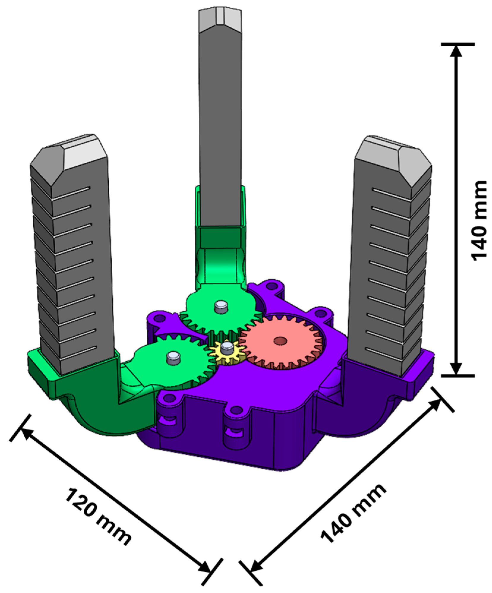
The main structural elements of the gripper, the finger support, were designed considering two principal requirements: (i) the arrangement of the actuators should produce a grip envelope comparable to the human hand; and (ii) the gripper main body should contain the mechanical elements for the reconfiguration of the actuators. A custom mechanism to enable the repositioning of the two mobile fingers according to the strategy depicted in Figure 1 was developed. The two fingers will be moved synchronously, with a range of motion of 60°; moreover, the mechanism was designed to operate exclusively at either end of their range of the reconfiguration motion. Considering these constraints, a practical solution is to use a single rotary actuator acting on the drive gear of a mechanism, such as the one depicted in Figure 5.
The transmission mechanism comprises four gears—one driving gear (red in Figure 5), one idle gear (yellow in Figure 5), and two driven gears (green in Figure 5)—directly obtained as part of the finger supports, whose axes serve as the pivot points for the fingers. The three larger gears have a module of 1.25, 24 teeth, primitive diameter of 30 mm, and a transmission ratio of 1:1. The Idler gear wheel has a module of 1.25, ten teeth, and a primitive diameter of 12.5 mm. This small number of teeth was chosen in order to reduce the footprint of the entire mechanism as much as possible. The thickness of the gears is 20 mm, and is equal to that of the finger support. This value guarantees sufficient strength to prevent the mechanism from breaking—considering a FFF fabrication with a thermoplastic polymer—and allows for the component to be manufactured more easily. The finger support was further developed integrating the gear mechanism into the structural part of the gripper, respecting the desired relative position of the soft actuators. The final dimensions of the gripper (visible in Figure 6) are 120 × 140 × 140 mm. Using experiments performed on a preliminary prototype featuring the described mechanism, a minimum torque to be provided by the rotary actuator of 0.45 Nm was estimated.
The interface between the finger and the support was designed with interference coupling so that the finger cannot move within its housing. Finally, a palm printed in a plastic polymer (PLA) was placed over the mechanism to close it (not shown in Figure 6).

2.4. Pneumatic Rotary Actuator

For the implementation of the reconfiguration mechanism, it was decided not to use commercial solutions such as the FESTO DRDD [23] and DRVS [24], but rather to develop a customized pneumatic rotary actuator, allowing for a greater scope for development and adaptability to the possibly varying shapes and sizes of the gripper. A tailor-made rotary actuator allows for greater freedom in choosing the gearing of the reconfiguration mechanism and the position of the mechanical parts. Moreover, the design of the rotation mechanism was driven by the application of design for additive manufacturing principles (namely, the parts integration principle), thereby pursuing the integration of the actuator within the device, with the main advantage being the ability to optimize the space usage and reduce the overall dimensions of the device itself. This choice has also allowed for a reduction in the production costs, and preserves the maximum design flexibility for future versions of the device. As previously explained, considering the gear ratio 1:1, the pneumatic rotary actuator needs to guarantee an angular range of motion of 60° clockwise and anti-clockwise. The devised actuator consists of the following components: crankcase, lid, and inner vane, shown in Figure 7. The operating principle relies on generating a pressure differential between the two chambers using pressurized air, which causes the vane to rotate. This vane, connected to the overhead gear system, enables the transition between the “120°” and the “Claw” configurations.
To ensure the sealing of the components, a commercial nitrile rubber gasket was integrated inside the carter at the output shaft housing, pausing the print during fabrication to allow for the placement of the component. A silicone gasket was placed between the two components to ensure the seal between the lid and the crankcase.

2.5. Fabrication and Actuation

Except for the soft actuators, all components were made by FFF 3D printing in PLA using a Prusa i3 Mk3S+ printer. In order to improve the sealing of the rotary actuator chamber, the casing and cap were made from 100% infill. The remaining components were manufactured with 20% infill, which was enough to guarantee the strength of the components, considering the limited interaction forces of the actuator. Preliminary tests on the pneumatic rotary actuator highlighted the need of a gasket around the vane to improve the pressure difference between the two chambers. A custom solution using a Dragonskin 30™ (Smooth-on, Inc., Macungie, PA, USA) silicone was designed; the gasket was casted in place using a set of specific 3D-printed molds. The Shore A hardness value of 30 offers good resistance to deformation and wear while allowing for good adherence to the external surface. Moreover, the friction between the gasket and the chambers walls produces a passive force that contributes to the stability of the grasping configuration, even when the rotary actuator is not pressurized. The actuator is able to generate a maximum torque of 0.93 Nm using pressurized air at 6 bar, which is more than sufficient to actuate the configuration mechanism, even considering the additional friction between the vane and the walls caused by the Dragonskin gasket. Grasping-force tests using the rigid PLA palm described above gave unsatisfactory results, as detailed in Section 3.1. The first version of the palm was hence switched with a silicone one in order to maximize the contact surface between the gripper and the objects and to increase the friction coefficient. The palm of the gripper was made of Ecoflex 00–50™ (Smooth-on, Inc., Macungie, PA, USA) silicone with Shore 00 hardness of 50. The pneumatic gripper actuation system was controlled by an “Arduino Uno” (Arduino LLC, Ivrea, Italy) microcontroller board and six solenoid valves, 12 v, 0–10 bar, 2/2. The diagram of the pneumatic system and the corresponding cyclogram are visible in Figure 8.
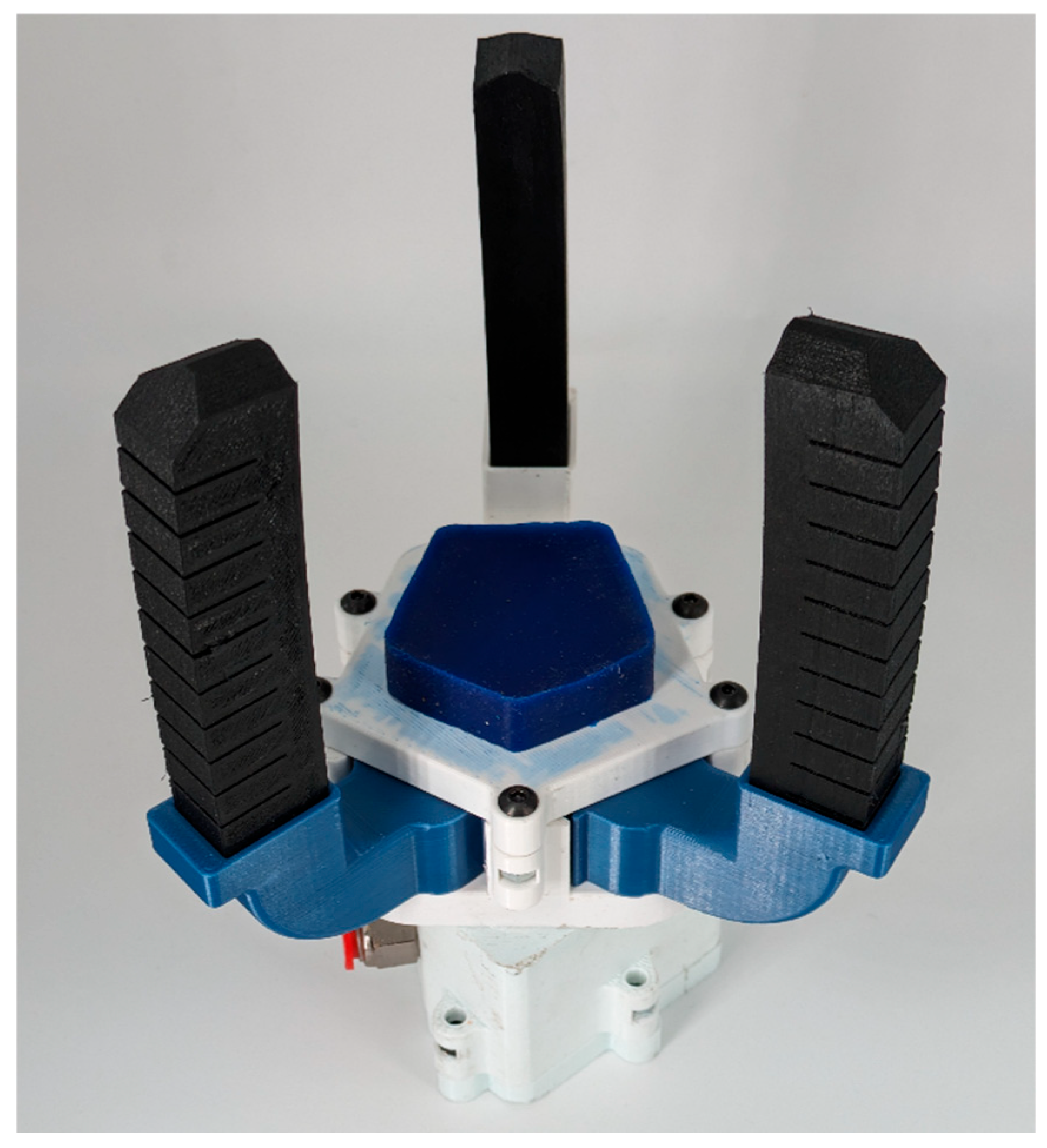
The actuation of the reconfiguration mechanism was tested with pressures up to 6 bar. When using the gripper, however, the actuation pressure used was limited to 4 bar for safety reasons, allowing for a satisfactory reconfiguration speed. With a pressure of 4 bar, the gripper was able to change configuration in 0.5 s. The finished gripper can be seen in Figure 9, with all the components properly assembled and integrated.

3. Validation Tests

Once the functioning of the gripper was verified, a series of experimental tests aimed at measuring the grasping forces and adaptability on different objects were carried out.

3.1. Grasping Force Test

The test was carried out by placing the test object in the center of the gripper palm and actuating the fingers at maximum pressure, i.e., 3 bar. These tests were realized using a set of three objects with typical shapes such as parallelepiped, cylinder, and sphere (Figure 10).
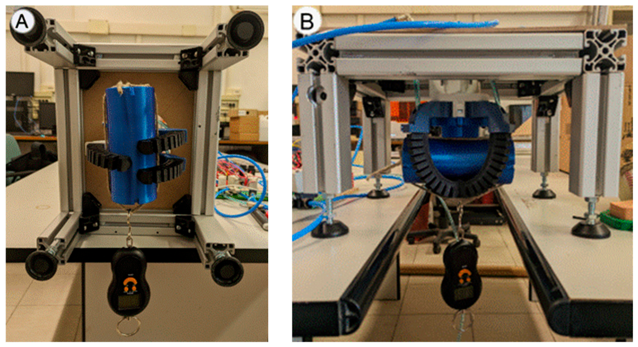
The force was measured and recorded using a digital dynamometer (sensitivity of 0.05 N) by pulling the object along the transversal and normal directions, respectively, shown in Figure 11.
Both transversal and normal forces were measured on all sample objects in the two-finger configurations (“claw” and “120°”) and with both palms, PLA and silicone. For each sample object, five measurements were taken for each of the two configurations. The average values and standard deviation for the PLA palm are shown in Table 5, and those for the silicone palm are shown in Table 6.
Graphs comparing the experimental results are shown in Figure 12, Figure 13, Figure 14 and Figure 15.
Experimental data show a significant increase in grasping forces with the use of the silicone palm, especially in the transversal force. It is also interesting to note that, even in the case of the normal forces, there is a slight increase in grasping forces when using the silicone palm. This is due to the greater deformability of silicone allowing the palm to adapt more closely to the shape of the object and thereby provide a better grip. Following the tests for the maximum grasping force generated by the manipulator, further experimental tests were carried out to assess the effect of a change in finger actuation pressure. A new series of measurements with transversal force was carried out by reducing operating pressure to 2.5 bar and 2 bar. The test was carried out with the manipulator equipped with the silicone palm on the spherical and cylindrical samples using, respectively, “120°” and “claw” finger configurations. Tests results are shown in Table 7 and Table 8.
The trend of the variation in the grasping force as a function of finger actuation pressure can be seen in Figure 16. The trend, to a good approximation, can be considered linear.
It is appropriate to compare our gripper with others to evaluate performance. However, it is not appropriate to include grippers based on different technologies, as this would lead to incorrect comparisons. Focusing on pneumatically actuated soft robotic grippers, performance metrics from the literature highlight a diverse range of force capabilities:
  • Tawk et al. [25] developed a modular soft gripper leveraging 3D-printed components, achieving a maximum lifting force of approximately 1.9 N under a pressure of 1.5 bar.
  • Wichiramala et al. [26] characterized the grasping forces of a 3D-printed TPU pneumatic actuator, which reached a peak force of about 2 N at 4 bar during blocked-force tests. These studies underscore the modest force outputs achieved with lightweight, flexible designs.
  • Dilibal et al. [27] introduced a custom-made soft gripper with embedded force sensors for industrial applications, attaining a maximum grasping force of 7.8 N at a lower pressure of 0.7 bar.
  • Hao et al. [28] took a different approach with a four-fingered soft robotic gripper fabricated from soft silicone. Their design achieved a maximum “pull-off force” of approximately 13.5 N at 0.7 bar, reflecting a combination of material compliance and effective mechanical design.
The proposed gripper achieves a peak grasping force of 17 N at 3 bar, which is competitive with grippers that use more complex actuation systems. Its performance is enhanced by a reconfigurable mechanism that allows for adaptation to various object geometries. However, individual actuators exhibit reduced blocked force compared to some of the alternatives mentioned earlier, due to material and fabrication constraints. While this limitation was an intentional compromise in the prototypal phase to validate the feasibility of the proposed concept, future iterations will focus on improving performance by optimizing the material properties and refining the manufacturing process.

3.2. Adaptability Test

As a final test, it was decided to carry out a series of tabletop grasping tests on objects characterized by different shapes and sizes, such as fruit and vegetables, to assess which configuration, between claw and 120°, performed the best. This type of object is commonly used as benchmark to evaluate the grasping capabilities of a soft gripper. The objects are shown in Figure 17, and their dimensions and weights are reported in Table 9.
For test validation purposes, ten grasping attempts were made on each object. For each attempt, the object was placed on the plane at the center of the manipulator. The gripper was positioned with the palm parallel to the plane, with the elongated fingers’ tip almost touching the surface. As a result, the palm was positioned at a rough distance of 95 mm. The test was deemed successful if the gripper could lift the object off the plane and hold it firmly, as shown in Figure 18. Table 10 reports the results of the test in terms of success rate.
Experimental results show that the object’s weight does not significantly affect grasping performance. Shape and dimensions, on the other hand, do; small objects, such as the potato, give the gripper a hard time, as do particular shapes such as the banana. The results of the egg test also show that the 120° configuration is more effective on spherically shaped objects. It is also important to highlight that surface characteristics might play an important role when combined with specific shapes; specifically, a smoother surface is more prone to slipping and can increase the chances of a missed grasping action. However, it should be noted that these tests were performed by placing the sample objects under the gripper and testing the gripper’s ability to grasp and lift them; this type of adaptability test is more difficult than the simple test of holding an object between the fingers. Despite the greater difficulty of the test, the gripper performed well. The test highlighted a possible direction for future improvements, implementing a different geometry for the distal part of the fingers, optimized for grasping small objects and increasing the dexterity of the system. In particular, certain geometries, such as claw-like structures or fingertip extensions, are designed to enhance precision and stability during delicate manipulation tasks. Future activities will be devoted to this purpose.

4. Conclusions

The aim of this study was the development of the hardware and main systems to pursue proof of concept of the gripper. This study began with an analysis of the state of the art in the field of soft grippers, with particular focus on pneumatic actuation and its potential for safe and adaptive interaction in rehabilitation and assistive robotics. The initial search through the Scopus and Web of Science databases led us to the creation of a gripper that was easier to make, implement, and control than those found in the literature, but which still manages to provide significant gripping force and has good adaptability to different objects. The development of this gripper led to the creation of a prototypal device capable of reconfiguring the fingers by means of an entirely pneumatic actuation, characterized by dimensions comparable to those of a human hand. Using FFF 3D printing, it was possible to realize a series of prototypes aimed at evaluating the functionality of alternative solutions. The gripper demonstrated rapid reconfiguration (≈0.5 s) and grasping forces exceeding 17 N on rigid targets, while functional tests confirmed adaptability to objects of varying shapes and sizes. Considering the grasping tests, it could be seen that the different finger configurations have variable effectiveness depending on the object to be grasped. Obviously, the shape and characteristics of the finger play a major role in determining its grasping performance. The current implementation still presents limitations due to the large number of components. The 2/2 valves were chosen for their ease of control; future developments could replace the four valves used for the rotary mechanism with a single 5/3 valve, thereby reducing overall system complexity and dimensions. This would also allow us to reduce the overall dimensions. The results achieved in this study lay the basis for further research into the most effective shapes and dimensions for the fingers, particularly in regard to fingertips. Moreover, future work could be oriented toward the experimentation of refined control strategies. With this respect, active control could be enabled by integrating force/deflection sensors in the actuators or applying computer vision techniques to monitor gripper–object interactions. The integration of a pressure regulation controlled by the Arduino could enable the device to perform dynamic grasping and adjust the forces exerted by the actuators with respect to the object grasped and its characteristics. The ultimate goal of this research is the integration of a control strategy that is able to recognize, through a network of different sensors, the ideal grasping conditions for a given object in terms of gripper configuration, exerted forces, and the relative position of the gripper with respect to the target. In conclusion, it can be said that the aim of this study, to realize a reconfigurable soft gripper, has been successfully achieved. The combination of versatility offered by the two possible finger configurations and the grasping forces generated by the gripper provides the robotic hand with a wide range of applications. Although the forces developed by our gripper may not surpass those of some existing examples, its adaptability and feasibility underline its innovative potential. This limitation, however, reflects the intentional prototypal focus of the current design phase, with future developments expected to deliver substantial improvements.
To significantly enhance both the intelligence and holding force of the device—aligning with the requirements for advanced manipulation—future work will focus on integrating high-performance components. In particular, improving active control and proprioception necessitates the inclusion of flexible bending sensors within the soft actuators [29]. This sensory feedback is essential for closing the control loop, enabling the system to accurately monitor the gripper’s deformation and kinematic state in real time. Such a capability facilitates dynamic grasping and compensates for the inherent non-linearities of soft materials.
Additionally, to substantially increase holding force and functional versatility, the next design iteration will incorporate bio-inspired adhesive fibrillar surfaces [30] at the fingertips. Drawing inspiration from gecko adhesion, these microstructured surfaces exploit high shear forces and van der Waals interactions to achieve a robust grip, significantly expanding load capacity and ensuring stable attachment, particularly on complex geometries where friction-based gripping is limited.
The successful integration of these sensory and performance-enhancing features is paramount to realizing a truly intelligent and adaptable soft robotic hand.

Author Contributions

Conceptualization, F.B. and L.G.; methodology, F.B., M.C. and L.T.; validation, F.B. and L.G.; investigation, M.C. and L.T.; data curation, M.C. and L.T.; writing—original draft preparation, M.C. and L.T.; writing—review and editing, F.B., M.C., L.T., L.P. and L.G.; visualization, L.P.; supervision, F.B., L.G. and Y.V. All authors have read and agreed to the published version of the manuscript.

Funding

This research received no external funding.

Data Availability Statement

The raw data supporting the conclusions of this article will be made available by the authors on request.

Acknowledgments

This work is supported by the Spoke 9 within the Italian National Research Programme (NRP) TUSCANY HEALTH ECOSYSTEM (THE), CUP: 83C22003920001.

Conflicts of Interest

The authors declare no conflicts of interest. The funders had no role in the design of the study; in the collection, analyses, or interpretation of data; in the writing of the manuscript; or in the decision to publish the results.

References

  1. Wang, Z.; Bao, S.; Zi, B.; Jia, Z.; Yu, X. Development of a novel 4-DOF flexible endoscopic robot using cable-driven multisegment continuum mechanisms. J. Mech. Robot. 2024, 16, 3. [Google Scholar] [CrossRef]
  2. Drotman, D.; Ishida, M.; Jadhav, S.; Tolley, M.T. Application-driven design of soft, 3-D printed, pneumatic actuators with bellows. IEEE/ASME Trans. Mechatron. 2019, 24, 78–87. [Google Scholar] [CrossRef]
  3. Lv, Z.; Xiao, F.; Chen, B.; Dong, R.; Liu, Z.; Wang, Y. Design and performance analysis of wavy nonrotating pneumatic soft actuator. J. Mech. Robot. 2024, 16, 2. [Google Scholar] [CrossRef]
  4. Jiao, Z.; Zhuang, Z.; Cheng, Y.; Deng, X.; Sun, C.; Yu, Y.; Li, F. Lightweight dual-mode soft actuator fabricated from bellows and foam material. Actuators 2022, 11, 245. [Google Scholar] [CrossRef]
  5. Mosadegh, B.; Polygerinos, P.; Keplinger, C.; Wennstedt, S.; Shepherd, R.F.; Gupta, U.; Shim, J.; Bertoldi, K.; Walsh, C.J.; Whitesides, G.M. Pneumatic networks for soft robotics that actuate rapidly. Adv. Funct. Mater. 2014, 24, 2163–2170. [Google Scholar] [CrossRef]
  6. MacCurdy, R.; Katzschmann, R.; Kim, Y.; Rus, D. Printable hydraulics: A method for fabricating robots by 3D co-printing solids and liquids. In Proceedings of the 2016 IEEE International Conference on Robotics and Automation (ICRA), Stockholm, Sweden, 16–21 May 2016; IEEE: Piscataway, NJ, USA; pp. 3878–3885. [Google Scholar] [CrossRef]
  7. Zhou, J.; Chen, S.; Wang, Z. A soft-robotic gripper with enhanced object adaptation and grasping reliability. IEEE Robot. Autom. Lett. 2017, 2, 2287–2293. [Google Scholar] [CrossRef]
  8. Batsuren, K.; Yun, D. Soft robotic gripper with chambered fingers for performing in-hand manipulation. Appl. Sci. 2019, 9, 2967–2977. [Google Scholar] [CrossRef]
  9. Townsend, W. The BarrettHand grasper—Programmably flexible part handling and assembly. Ind. Robot 2000, 27, 181–188. [Google Scholar] [CrossRef]
  10. Mishra, A.K.; Del Dottore, E.; Sadeghi, A.; Mondini, A.; Mazzolai, B. SIMBA: Tendon-driven modular continuum arm with soft reconfigurable gripper. Front. Robot. AI 2017, 4, 4. [Google Scholar] [CrossRef]
  11. Lu, Q.; Baron, N.; Clark, A.B.; Rojas, N. Systematic object-invariant in-hand manipulation via reconfigurable underactuation: Introducing the RUTH gripper. Int. J. Robot. Res. 2021, 40, 1402–1418. [Google Scholar] [CrossRef]
  12. Mathew, A.T.; Hussain, I.; Stefanini, C.; Ben Hmida, I.M.; Renda, F. ReSoft gripper: A reconfigurable soft gripper with monolithic fingers and differential mechanism for versatile and delicate grasping. In Proceedings of the 2021 IEEE 4th International Conference on Soft Robotics (RoboSoft), New Haven, CT, USA, 12–16 April 2021; IEEE: New York, NY, USA; pp. 372–378. [Google Scholar] [CrossRef]
  13. Chappell, D.; Bello, F.; Kormushev, P.; Rojas, N. The Hydra Hand: A mode-switching underactuated gripper with precision and power grasping modes. IEEE Robot. Autom. Lett. 2023, 8, 7599–7606. [Google Scholar] [CrossRef]
  14. Gao, Y.; Huang, X.; Mann, I.S.; Su, H.J. A novel variable stiffness compliant robotic gripper based on layer jamming. J. Mech. Robot. 2020, 12, 5. [Google Scholar] [CrossRef]
  15. Zeng, X.; Su, H.J. A high performance pneumatically actuated soft gripper based on layer jamming. J. Mech. Robot. 2023, 15, 1. [Google Scholar] [CrossRef]
  16. Lu, Z.; Guo, H.; Zhang, W.; Yu, H. GTac-Gripper: A reconfigurable under-actuated four-fingered robotic gripper with tactile sensing. IEEE Robot. Autom. Lett. 2022, 7, 7232–7239. [Google Scholar] [CrossRef]
  17. Hao, T.; Xiao, H.; Liu, S.; Zhang, C.; Ma, H. Multijointed pneumatic soft hand with flexible thenar. Soft Robot. 2022, 9, 745–753. [Google Scholar] [CrossRef] [PubMed]
  18. Liu, X.; Zhao, Y.; Geng, D.; Chen, S.; Tan, X.; Cao, C. Soft humanoid hands with large grasping force enabled by flexible hybrid pneumatic actuators. Soft Robot. 2021, 8, 175–185. [Google Scholar] [CrossRef] [PubMed]
  19. Yan, J.; Xu, Z.; Shi, P.; Zhao, J. A human-inspired soft finger with dual-mode morphing enabled by variable stiffness mechanism. Soft Robot. 2022, 9, 399–411. [Google Scholar] [CrossRef]
  20. Hu, W.; Alici, G. Bioinspired three-dimensional-printed helical soft pneumatic actuators and their characterization. Soft Robot. 2020, 7, 267–282. [Google Scholar] [CrossRef]
  21. Cheng, P.; Lu, Y.; Wu, C.; Yan, B. Reconfigurable bionic soft pneumatic gripper for fruit handling based on shape and size adaptation. J. Phys. D Appl. Phys. 2023, 56, 044003. [Google Scholar] [CrossRef]
  22. Torzini, L.; Puggelli, L.; Volpe, Y.; Governi, L.; Buonamici, F. Characterization of fatigue behavior of 3D printed pneumatic fluidic elastomer actuators. Int. J. Adv. Manuf. Technol. 2024, 134, 2725–2736. [Google Scholar] [CrossRef]
  23. Semi-Rotary Drives DRRD, Twin Pistons. Available online: https://www.festo.com/catalogue/ (accessed on 17 May 2024).
  24. Semi-Rotary Drive DRVS. Available online: https://www.festo.com/catalogue/ (accessed on 17 May 2024).
  25. Tawk, C.; Mutlu, R.; Alici, G. A 3D printed modular soft gripper integrated with metamaterials for conformal grasping. Front. Robot. AI 2022, 8, 799230. [Google Scholar] [CrossRef] [PubMed]
  26. Wichiramala, K.; Opasjirawiroj, S.; Chongpita, N.; Chaichaowarat, R. Soft pneumatic actuator from 3D-printed TPU: Fabrication and grasping force characterization. In Proceedings of the 2023 IEEE International Conference on Robotics and Automation (ICRA), London, UK, 29 May–2 June 2023. [Google Scholar]
  27. Dilibal, S.; Sahin, H.; Danquah, J.O.; Emon, M.O.F.; Choi, J.-W. Additively manufactured custom soft gripper with embedded soft force sensors for an industrial robot. Int. J. Precis. Eng. Manuf. 2021, 22, 709–718. [Google Scholar] [CrossRef]
  28. Hao, Y.; Gong, Z.; Xie, Z.; Guan, S.; Yang, X.; Ren, Z.; Wang, T.; Wen, L. Universal soft pneumatic robotic gripper with variable effective length. In Proceedings of the 35th Chinese Control Conference, Chengdu, China, 27–29 July 2016; pp. 6109–6114. [Google Scholar] [CrossRef]
  29. Peng, Y.; Li, S.; Xia, Z.; Chen, X.; Zhang, F.; Zhong, L.; Liu, W. Recent advances in flexible bending sensors and their applications. Int. J. Smart Nano Mater. 2024, 15, 697–729. [Google Scholar] [CrossRef]
  30. Liu, J.; Yao, Y.; Chen, S.; Li, X.; Zhang, Z. A strong and reversible adhesive fibrillar surface based on an advanced composite with high strength and strong adhesion. Int. J. Smart Nano Mater. 2023, 14, 103–121. [Google Scholar] [CrossRef]
Figure 1. Schematic diagram of gripper configurations (a) mimicking the fingers of human hand (b).
Robotics 14 00152 g001
Figure 2. Isometric (a) and section (b) view of the proposed PneuNet finger.
Robotics 14 00152 g002
Figure 3. Comparison of two actuators operating at the same pressure, but with different chamber sections: (A) initial chamber design; (B) optimized chamber design. Stress intensity is represented by a color gradient, ranging from blue (low) to red (high).
Robotics 14 00152 g003
Figure 4. Comparison of simulated and real models. Bending motion upon the application of positive internal pressure of: (A) 1 bar; (B) 2 bar; (C) 3 bar.
Robotics 14 00152 g004
Figure 5. Reconfiguration mechanism: gear 1, driving; gear 2 and 3, driven.
Robotics 14 00152 g005
Figure 6. Finger support: overall dimensions.
Robotics 14 00152 g006
Figure 7. Components of the pneumatic rotary actuator: lid (A), vane (B), nitrile commercial rubber gasket (C), crankcase with silicone gasket (D).
Robotics 14 00152 g007
Figure 8. Pneumatic system of the gripper (a), and cyclogram of the functioning valves (b).
Robotics 14 00152 g008
Figure 9. The developed gripper composed of soft silicone palm, TPU actuators, and a PLA structure.
Robotics 14 00152 g009
Figure 10. Sample of the objects used during the tests.
Robotics 14 00152 g010
Figure 11. Forces of the grasping test: (A) transversal grasping force; (B) normal grasping force.
Robotics 14 00152 g011
Figure 12. Claw parallel forces at 3 bar.
Robotics 14 00152 g012
Figure 13. 120° Parallel forces at 3 bar.
Robotics 14 00152 g013
Figure 14. Claw normal forces at 3 bar.
Robotics 14 00152 g014
Figure 15. 120° normal forces at 3 bar.
Robotics 14 00152 g015
Figure 16. Trend of grasping force variation. Parallel force measurements. Certain deviation bars are not shown, as they are visually negligible; refer to Table 7 and Table 8 for numerical values.
Robotics 14 00152 g016
Figure 17. Sample of the objects used in the grasping tests.
Robotics 14 00152 g017
Figure 18. Example of successful grasping of an object (avocado).
Robotics 14 00152 g018
Table 1. Blocked-force finger.
Pressure [bar]Force [N]Standard Deviation [N]
1 1.070.03
2 2.610.04
3 3.730.12
Table 2. Parameters comparison between the initial design and the refined design.
Initial DesignRefined Design
SectionRectangular 13 × 9 mm,
filleted corners R3
Rectangular 14.8 × 11.7 mm,
sharp corners
Wall Thickness2 mm1.6 mm
Bellow Cavity Length4.2 mm5 mm
Table 3. Material parameters utilizing the Ogden hyperelastic material model.
Material ModelMU1 (Pa)A1MU2 (Pa)A2
2° order Ogden1,094,1302.91−12,034,197−0.56
Table 4. Comparison between simulated and experimental bending angles at different applied pressures.
Pressure [bar]Simulated Bending AngleExperimental Bending Angle
1 36.7°35.9°
2 48.9°47.7°
3 70.5°68.7°
Table 5. PLA palm grasping test at 3 bar.
CylinderParallelepipedSphere
Force [N]Standard Deviation [N]Force [N]Standard Deviation [N]Force [N]Standard Deviation [N]
Claw transversal force2.060.023.440.019.040.37
120° transversal force3.960.083.490.026.550.11
Claw normal force11.90.4714.060.216.080.18
120° normal force9.390.1513.430.2515.520.64
Table 6. Silicone palm grasping test at 3 bar.
CylinderParallelepipedSphere
Force [N]Standard Deviation [N]Force [N]Standard Deviation [N]Force [N]Standard Deviation [N]
Claw transversal force14.730.0714.30.1417.160.44
120° transversal force10.580.1411.690.0517.721.87
Claw normal force12.320.2414.970.2716.630.2
120° normal force11.130.1513.990.5616.410.29
Table 7. Sphere 120° configuration.
Pressure [bar]Experimental Grasping ForceStandard Deviation
2.05.700.11
2.510.910.09
3.017.160.44
Table 8. Cilinder claw configuration.
Pressure [bar]Experimental Grasping ForceStandard Deviation
2.04.940.01
2.58.130.18
3.014.730.07
Table 9. Dimensions and weight of the sample objects used in the grasping test.
Length [mm]Width [mm]Height [mm]Weight [g]
Egg70454533
Potato75354096
Banana1604043245
Avocado906060297
Aubergine1106055359
Kiwi704040123
Pepper1507070430
Table 10. Grasping test result.
EggPotatoBananaAvocadoAubergineKiwiPepper
Claw60%0%20%90%100%100%100%
120°80%0%10%50%40%100%100%
Disclaimer/Publisher’s Note: The statements, opinions and data contained in all publications are solely those of the individual author(s) and contributor(s) and not of MDPI and/or the editor(s). MDPI and/or the editor(s) disclaim responsibility for any injury to people or property resulting from any ideas, methods, instructions or products referred to in the content.