Abstract
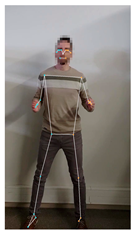
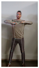
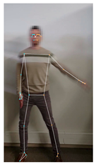
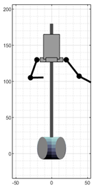
This paper presents our first results obtained in the direction of using a humanoid robot to perform a robot dance at a level comparable to that of a human dancer. The scope of this first approach is limited to performing an offline analysis of the movements of the arms of the dancer and to replicating these movements with the arms of the robot. To this end, the movements of a dancer performing a static robot dance (without moving the hips or feet) were recorded. These movements were analyzed offline using the MediaPipe BlazePose framework, adapted to the mechanical configuration of the arms of the humanoid robot, and finally reproduced by the robot. Results showed that MediaPipe has some inaccuracies when detecting sudden movements of the dancer’s arms that appeared blurred in the images. In general, the humanoid robot was capable of replicating the movement of the dancer’s arms but was unable to follow the original rhythm of the robotic dance due to acceleration limitations of its actuators.
1. Introduction
Humanoid robots are usually designed to emulate the anatomy of the human body, its movements, behavior, and facial expressions [1,2]. In general, the use of humanoid robots is strongly associated with environments in which interaction or emotional attachment between humans and the robot constitutes a key aspect of the task to be performed. A clear example can be seen in home-service robots [3,4], guidance robots [4,5,6], walking assistant robots [7,8], interaction robots [9,10], companion robots [11,12], or merely conversational robots [13,14,15].
In the case of communicating emotions and attitudes, Mehrabian et al. [16] concluding that 55% of the communication is based on the body language, 38% in the tone of the voice used, and 7% in the words used in the message. Regarding the body language, Ekman et al. [17] stated that human beings use similar face gestures to communicate basic emotions, a factor that facilitates the establishment of basic communications between people using different languages and raised in different cultures.
In the case of human–robot interaction, Mori et al. [18] proposed the uncanny valley theory to describe the impression given by robots who closely resemble the physical aspect of humans and their behavior but still lack the level of detail required to be perceived as fully human, resulting in a sense of unease or discomfort in human observers. In this regard, Mori emphasized the need of designing robots that behave as closely as possible to humans in order to prevent rejection and foster emotional engagement [19,20]. In this direction, the generation of facial emotions in robots has been addressed using different approaches [21,22,23]. Lin et al. [24] analyzed the minimum number of actuators required to replicate an anthropomorphic face. Hyng et al. [25] proposed a system to automatically generate facial expressions in different robots by using genetic algorithms, using a facial expression recognizer as a fitness function. The system was evaluated using a humanoid robot equipped with a realistic human face controlled by 16 motors, with each motor’s displacement encoded by a gene that evolved adaptively.
1.1. Dancing Robots
It is widely known that dancing to music has long served as a catalyst for social interaction among humans [26,27]. Peng et al. [28] classified robotic dance into four categories: synchronization with music (using musical beats as a means to synchronize movements), imitation of human dance motions (the robot reproduces movements performed by a human dancer), cooperative human–robot dance (the human and robot respond to each other’s movements), and creation of robotic choreography (generating new choreographies to maintain the audience’s interest). Some robotic dance proposals available in scientific literature are listed below in chronological order.
Michalowski et al. [29] described the development of a dancing robot designed for rhythmic social interaction. The small, figure-eight-shaped robot was equipped with an internal mechanism driven by four motors, allowing it to shift its inclination in response to ambient musical and visual cues. Despite its simplicity, the robot was effective at engaging children during a dancing activity. Nakaoka et al. [30] focused on leg movements in dance, proposing a Learning from Observation (LfO) approach to enable the legged humanoid robot HRP-2 [31] to reproduce a dance captured from a human demonstration. Xia et al. [32] performed autonomous real-time robot dancing with the NAO robot. In this case, robot dancing was driven by a hidden Markov model analyzing the beats and emotions detected in music. Similarly, Okamoto et al. [33] applied the Zero Moment Point (ZMP) method to control the poses during a dance choreography performed by the HRP-2 robot. In this case, the robot was able to listen to music with varying tempos and perform a dance without exceeding its motor limitations. Okamoto found that certain fixed postures, or keyposes, were essential to the dance, as they defined anchor points used to develop whole-body dance motions. Ramos et al. [34] proposed a dance algorithm for the humanoid robot HRP-2. In this case, the choreographies were based on the use of a motion capture system to track the movements of a person. The objective was to perform real-time and fine-balanced dance movements by evaluating the use of inverse dynamics instead of inverse kinematics for the generation of complex humanoid robot movements. Gkiojas et al. [35] developed a dancing robot application to be embedded in the humanoid robot NAO. This proposal was based on the use of a convolutional neural network for real-time beat tracking. The choreographies generated were based on a set of predefined poses and a transition probability matrix. Qin et al. [36] proposed a dance algorithm for humanoid robots also driven by a hidden Markov model. However, in this case, the dance was created by dividing the music into a sequence of phrases whose emotions are choreographed combining a random number of actions. The advantage of this proposal is that the same music can generate different dance patterns on a humanoid robot.
1.2. MediaPipe Framework for Human Body Pose Estimation
Human body pose estimation has promising applications in a wide range of fields such as gestural analysis for health evaluation [37], human supervision [38], sign language recognition [39], imitation by learning [40], human–robot interaction [41], etc. The development of human body pose estimators has been fostered by the application of deep-learning architectures based on convolutional neural networks [42,43]. In 2020, Bazarevsky et al. [44] from Google Research presented BlazePose, a real-time body pose tracking using a lightweight convolutional neural network architecture. BlazePose was able to predict and return the position of the joints of a human body from an image.
The novelty of BlazePose [44] lies in predicting heatmaps for all body joints using an encoder–decoder network architecture, combined with an additional encoder that provides the coordinates of all the joints. The pipeline of the algorithm is based on the initial application of a body pose detector and, in the following frames, a pose tracker is used to predict the presence of a person, limiting the region of the frame analyzed. This pipeline is restarted when the tracker detects no person in the frame. This approach avoids the use of a heatmap branch and, as a result, the convolutional neural network architecture is lightweight enough to be applied in real-time body pose estimation on low-performance computers and mobile phones. However, the drawback of this approach is the limitation to the detection and tracking of only one person. BlazePose is offered in the suite of libraries and tools MediaPipe [45,46], which is implemented as an open-source cross platform framework for real-time and low-latency body, hand, and face pose estimation.
The real-time performances of the MediaPipe framework [45] have been demonstrated in several featured examples [47]. Güney et al. [37] used MediaPipe to analyze videos of hand movements in Parkinson’s patients. The objective was to estimate hand movement frequency in order to automate tremor analysis before and after oral medication, thereby quantifying its effect. Jeong et al. [48] used MediaPipe to monitor the risk of musculoskeletal disorders caused by repetitive working postures in industrial sites. Güney et al. [49] used the MediaPipe framework to study the effect of age and gender on the glabellar tapping reflex, which is a blink reflex that can be analyzed for diagnostic purposes, as it is correlated with certain brain disorders [50]. Kim et al. [38] presented a 3D human pose estimation system using MediaPipe to monitor seniors living alone, with the goal of detecting domestic falls and assess the severity of injuries. Supanich et al. [51] used the MediaPipe framework to monitor elderly individuals at home while performing their daily exercise routines, detecting incorrect postures to help prevent injuries. Zhang et al. [52] used this framework to assess the range of motion of patients suffering from common health conditions such as frozen shoulder and other common spinal diseases. Results showed that the use of MediaPipe, in combination with YOLOv5, was successful in analyzing, identifying and evaluating multiple posture-affecting disorders. In a similar direction, Amprimo et al. [53] applied the MediaPipe framework in clinical environment to assess hand dysfunctions and provide objective rehabilitation metrics. Garg et al. [54] and Chaudhary et al. [55] assessed the MediaPipe framework to guarantee a correct posture and technique during yoga exercises.
The MediaPipe framework is also tailored for hand detection. Bora et al. [56] used it to extract hand joint coordinates for recognizing signs and gestures from various local languages of India. They created an Assamese Sign Language dataset, which was used to train a feed-forward neural network, achieveing 99% accuracy in sign and gesture recognition. In a similar approach, Wang et al. [57] used the MediaPipe framework to detect 64 words and phrases in Argentinian sign language.
In terms of device and robot control, Alexandre et al. [58] proposed the use of MediaPipe to recognize hand gestures performed by an operator to control multiple mobile robots in order to optimize teleoperation time. Compared to manual control, in which a joystick was used to control the robot, the use of hand gestures increased the operator’s idle time from approximately 6% to 90%. Rhee et al. [59] assessed the possibility of using the MediaPipe framework to track individual fingers for the remote control of surgical equipment, such as the well-established Da Vinci robot [60]. The main goal of their proposal was to reduce the physical fatigue that surgeons experience due to bad posture maintained during the length of a medical procedure. This was achieved by setting up a remote station equipped with cameras and a Head Mounted Display (HMD), while using MediaPipe to track the surgeon’s fingers, thus allowing him to operate from a comfortable position. Results showed that the delay added by using the MediaPipe framework for hand tracking was 12 ms, which is low enough to be considered negligible. This work also reported some inaccuracies of MediaPipe when obtaining 3D coordinates of the hands, which were solved by using 4 cameras to improve depth perception.
Finally, another proposal to overcome MediaPipe depth perception problem was the use of stereo-vision techniques [61]. In this case, a stereo-vision camera was used to obtain two simultaneous images of the hand; then, MediaPipe was used to determine the coordinates of the articulations within both images; and finally, this information was used to triangulate the 3D-coordinates of each articulation of a hand.
1.3. Dancer Pose Estimation Using MediaPipe
In more art-oriented contexts, the MediaPipe framework has been widely used to track the movements of dancers in video-recorded performances. Several recent proposals available in scientific literature are listed below in chronological order.
Lin et al. [62] used the Mediapipe framework to capture the skeleton and body joints of dancers in an attempt to determine the portrayed emotion of the dance. The dance was also transferred to a robotic arm. Although the mapping from the dancer pose to the robot pose was not specified, the authors highlighted the complexity of this process due to the sophisticated movements performed by dancers, as well as the considerable demanding hardware requirements to run their proposed solution. Solkar et al. [63] developed a system to assist a dancer in identifying deviations relative to previous recorded performances based on the motion estimated by the MediaPipe framework. The system was applied to an Indian classical dance based on body and hand gestures by using Fast Dynamic Time Warping (FDTW) [64] with cosine distance as a measure of similarity to compare gestures and motions. In a similar scenario, Aishwarya et al. [65] used the MediaPipe framework to study 30 female dancers. The body poses of the dancers were analyzed to identify postural deviations and gain insights into dance-related pain and injuries.
Kumar et al. [66] used MediaPipe to recognize another Indian classical dance based only on hand gestures. In this case, a Support Vector Machines (SVM) [67] model trained with a labeled dataset was used to identify and interpret gestures enabling future applications for teaching and grading dancers. In a similar direction, Wang et al. [68] developed a method to automatically identify emotions expressed in dances by analyzing a set of specific parameters related to the Laban Movement Analysis, such as the distance between certain parts of the body, the velocity of the movements, and their accelerations. The MediaPipe framework was used to extract the required key features for the analysis and train several machine learning algorithms to automatically detect two emotions, labeled as “afraid” and “happy”.
Another interesting application for the Mediapipe framework was proposed recently by Mccormick et al. [69] who used it for tracking and digitize the movements performed by dancers who shared their dances on social media, allowing them to be imported into a virtual environment using the Unity framework.
In the context of enabling robots to imitate dances, Costilla Caballero [70] proposed the use of MediaPipe to track the movements of a person in order to replicate them in a NAO robot. However, the author highlighted the need to improve the method used to calculate the angles for the servos of the NAO robot, hinting the difficulty of this process. Finally, Hong et al. [71] used the onboard camera of the HRP-4 robot to recognize a dancer’s body gestures, with the objective of enabling the robot to respond to the dancer’s actions in real time. In this case, the MediaPipe framework was employed to track the body movements of a professional dancer in real time and trigger autonomous dance responses.
1.4. New Contribution
This paper presents our first results obtained in the direction of enabling a humanoid robot to perform a robot dance at a level comparable to that of a human dancer. The scope of this preliminary approach is limited to an offline analysis of the dancer’s arm movements and to replicating these movements with the arm of the robot.
This paper is inspired by the idea proposed by Mccormick et al. [69] to digitize short dances shared on social media, the algorithm developed by Ramos et al. [34] for computing dynamically consistent movements based on motion capture data, and the approach introduced by Costilla Caballero et al. [70] for controlling the dance movements of the NAO Robot.
In this approach, the human dancer was a member of the research group with prior experience in a related dance style known as breakdancing. The dance recorded was performed without moving the hips or feet, and the dancer remained always facing the camera to prevent occlusions between body parts. The main contributions of this study are:
- The evaluation of the MediaPipe BlazePose framework for the offline extraction of the skeletal mesh of the dancer from the video-recorded dance;
- The analysis of the execution time of the MediaPipe BlazePose framework on 1080 × 1920 resolution videos under various configuration settings;
- The development of a virtual model for the humanoid robot and the application of a minimization function to match the skeletal mesh of the dancer and the angles of the arms of the virtual model;
- The extraction of the Euler angles of the servomotors that control the arms of the humanoid robot;
- The appropriate generation of the motion commands to replicate the robot dance with the humanoid robot.
The novelty of this contribution is the integrated implementation of all these procedures with the goal of making a full-size humanoid robot imitate a robot dance recorded on video and drawing conclusions from this experience.
1.5. Paper Structure
The paper is structured as follows. Section 2 introduces the materials and methods: the reference mobile robot, the robot dance choreography selected, and the MediaPipe framework. Section 3 describes the robot dance implementation in the robot. Section 4 presents and discusses the practical results obtained. Section 5 draws the conclusions and outlines future research directions.
2. Materials and Methods
The materials and methods employed in this study are: (i) the APR humanoid robot, (ii) the MediaPipe BlazePose machine learning framework for extracting a 3D skeletal mesh with the joint coordinates of a person from a picture or video frame, (iii) a Virtual Robot Model designed to replicate the kinematics of the APR servomotors, and (iv) a minimization function that transforms the 3D joint coordinates into approximated Euler angles, which are subsequently mapped to the servomotor angles of the physical robot.
2.1. Humanoid Robot
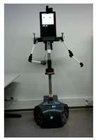
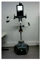
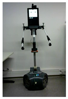
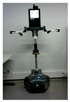
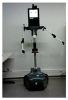
The platform used in this work is a humanoid, three-wheeled omnidirectional robot developed by the Automation and Robotics Laboratory of the University of Lleida, Spain [72]. This robot was initially conceived as a remotely operated assistive tool to provide real-time, online care for the elderly but later evolved into an autonomous mobile platform with support for multiple sensing devices [73]. The physical design of the robot emulates human morphology, featuring a total height of 1.76 m, a digital display for rendering the characteristic APR face, and articulated arms primarily intended for gestural communication and interaction. The robot’s central processing unit consists of a PC powered by an Intel Core i7-6700K processor, responsible for processing all data acquired from the on-board embedded sensors. These include an indoor 2D LiDAR sensor (Hokuyo UTM-30LX), multiple RGB cameras, passive infrared (PIR) sensors, and a touch screen designed for rapid human–robot interaction. The robot has a main electronic control board that drives the motors attached to its omnidirectional wheels. Each arm is actuated through a chain of four interconnected MX-28T digital servomotors, including three servomotors for shoulder articulation, and one for the elbow joint. The kinematic representation, the assembly view, and the motion limitations of the arms of the robot are detailed in [74]. Images of the robot are included throughout the work.
2.2. MediaPipe BlazePose
MediaPipe BlazePose is a machine learning (ML) framework for human pose estimation developed by Google Research [45,46]. The pose estimation is based on a lightweight convolutional neural network architecture for high-fidelity body pose tracking that is tailored for real-time inference. This convolutional neural network has been trained using extensive datasets containing labeled human poses, enabling the recognition of a wide variety of poses across different body types.
MediaPipe BlazePose is based on a single frame analysis and returns only the most predominant or nearest human body. It returns 33 2D landmarks defining the human body, such as shoulders, elbows, wrists, hips, knees and ankles, which allows accurate movement tracking. MediaPipe also returns a mask that distinguishes between the detected human body and the background. A comprehensive list of all the landmarks, along with their identification numbers, is presented in Table 1.

Table 1.
Description of the pose landmarks detected by MediaPipe BlazePose.
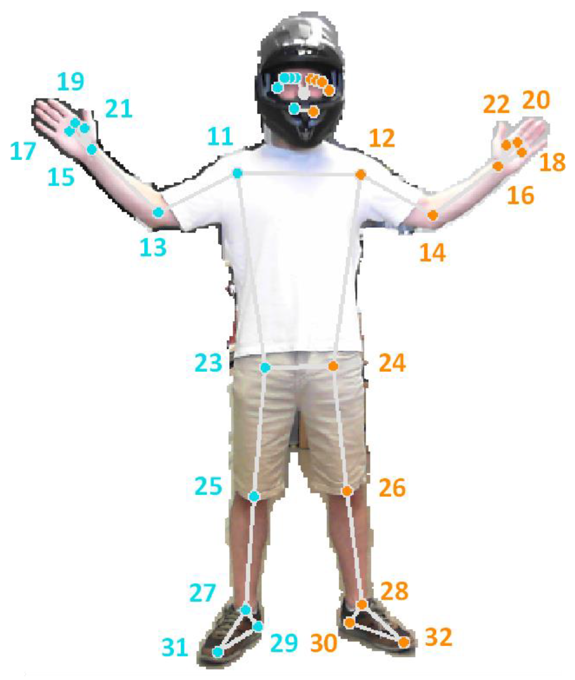
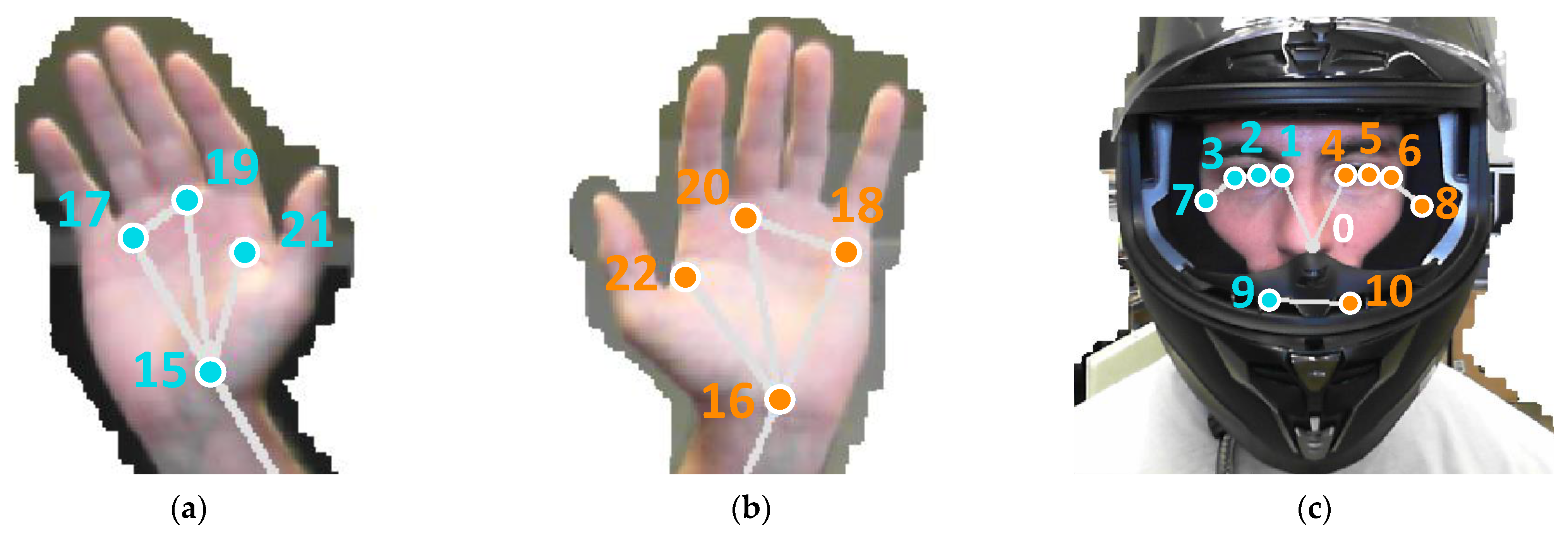
A representation of the landmarks detected by MediaPipe BlazePose is presented in Figure 1, showing the image of one of the authors of this paper along with the 33 characteristic body landmarks. For further detail, close-up images of the hands and face landmarks are presented in Figure 2. In both figures, the background of the image has been removed using the mask retrieved by the MediaPipe BlazePose framework. Although MediaPipe BlazePose is capable of tracking individual finger positions, this information is not reported in this study, as it is not relevant to the objectives of this study.
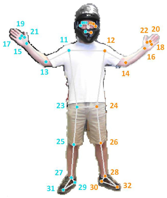
Figure 1.
Pose landmarks computed by the MediaPipe BlazePose framework from an image of a person wearing a helmet. The figure shows the human body segmentation mask, the 2D skeletal projection (lines), and the detected landmarks (dots) with its numerical labels.
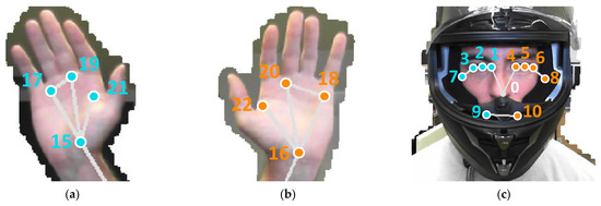
Figure 2.
Details of the pose landmarks detected with MediaPipe BlazePose in: (a) left hand, (b) right hand, and (c) head (wearing a helmet). The numerical labels have been manually added afterwards.
The MediaPipe BlazePose framework provides three distinct sets of data: (i) normalized pose landmarks, (ii) world pose landmarks, and (iii) pose landmark visibility. For the normalized pose landmarks (values ranging from 0 to 1), the and coordinates are expressed relative to the image width and height, while the coordinate represents an estimated depth value, defined as the distance from the camera to the midpoint of the hips. In contrast, the world pose landmarks are expressed as absolute distances between landmarks, using the midpoint of the hips as the origin of the coordinate system. Finally, the landmark visibility is represented by a numeric value ranging from 0 to 1, indicating the probability of a given landmark being visible in the image, considering possible occlusions caused by other body parts. In this paper, we focused on the arm-related landmarks, specifically the upper torso landmarks (Figure 1, indices 11, 12, 13, 14, 15, 16, 23 and 24) of the person detected.
It is important to mention that, by default, MediaPipe BlazePose sets a minimum visibility threshold of 0.5. Consequently, if any joint has a visibility value lower than 0.5, the links of the skeletal mesh will not be displayed in the processed image, as the model will assume that said joint was not visible due to occlusion with other body parts.
2.3. Robot Dance
As previously stated, the objective of this paper is to allow a humanoid robot to replicate the arm movements of a dancer performing a robot-like dance. To this end, a robot dance choreography was prepared inspired in the performance delivered by the dancer Plasteed during the opening move of the Back to the Future Battle [75] that became viral in 2020, surpassing 13 million views in a relatively short period. The reference one-minute-long robot dance begins in the 10th second of the video and its distinguishing feature is that the dancer emphasizes arm motions while maintaining an expressionless (robotic) face. As is common in this style of robot dance, the dancer’s movements are strongly influenced by the periodic rhythm of the accompanying music, predominantly dictated by instruments such as the bass or the drums.
Figure 3 shows a set of snapshots of the robot dance choreography recorded for the development of this work. The choreography consists of a series of periodic, short arm movements, producing the impression that its arms are mechanically actuated.

Figure 3.
Ten representative snapshots extracted from the video recording of the robot-like dance used in this study.
3. Procedure for Dance Imitation Based on MediaPipe BlazePose
This section presents the offline procedure developed to extract the joints coordinates of a dancer from the frames of a video using MediaPipe BlazePose, calculate the corresponding angles for the joints of the humanoid robot using a Virtual Robot Model (VRM) and a minimization algorithm, and send the corresponding motion commands for the arms to replicate the dance in the robot.
Transferring the movement from a human dancer to a humanoid robot is far from a simple task. Although the coordinates of each joint can be obtained using the MediaPipe framework, the biomechanical differences between the human body and the robot prevent a direct mapping between the joint angles of the robot and those derived from the MediaPipe skeletal mesh [70]. Moreover, the presence of redundant articulations and the hard limits of the servomotors further increase the complexity of this task [76,77]. This problem has been addressed with the definition of a minimization function to find the servomotor angles of the robot that best resembles the pose of the skeletal mesh obtained using MediaPipe.
To this end, a virtual representation of the humanoid robot, referred to as the Virtual Robot Model (VRM), has been developed. The VRM is designed to accurately replicate the mobility capabilities of the real APR robot’s arms by incorporating all movement constraints imposed using multiple concatenated digital servomotors, which are responsible for driving each arm. It is important to note that the physical structure of the APR robot was pre-established prior to the commencement of this project. Consequently, the arrangement of the servomotors that compose the robot’s arms is fixed and cannot be modified. The characteristics of the VRM are presented in Section 3.2.
Once the VRM is created, the skeletal mesh obtained from the MediaPipe framework is re-arranged to match the exact dimensions and orientation of the VRM, ensuring a direct correspondence between the arm joints of both models (Section 3.2). In this development stage, a minimization algorithm is employed to reduce the positional error of key arm landmarks between the skeletal mesh and the VRM by iteratively adjusting the joint angles of the VRM (Section 3.3).
3.1. Skeletal Mesh Post-Processing
As previously mentioned, MediaPipe relies on a lightweight convolutional neural network architecture designed to estimate the body pose of the closest person detected in the analyzed image. In this study, the video is centered on a single dancer, with no other individuals present in the frames; therefore, this limitation does not pose any issue. MediaPipe can be configured to return either normalized pose landmarks—where joint coordinates are expressed relative to the image’s width and height—or world landmarks, in which the algorithm attempts to estimate the real-world scale of the skeletal mesh. For this work, MediaPipe was configured to return world coordinates, as normalized landmarks were found to be more prone to produce depth distortions. Additionally, this algorithm can also be configured to use more complex models when extracting the body pose from an image (value between 0 and 2). A higher Model Complexity value will generate more accurate results but will increase the computation time of each frame; on the other hand, a lower Model Complexity value will allow the algorithm to process each frame faster but will yield worst results. In this case, the Model Complexity setting is set to 1, this being its default value, this decision is justified in the results section.
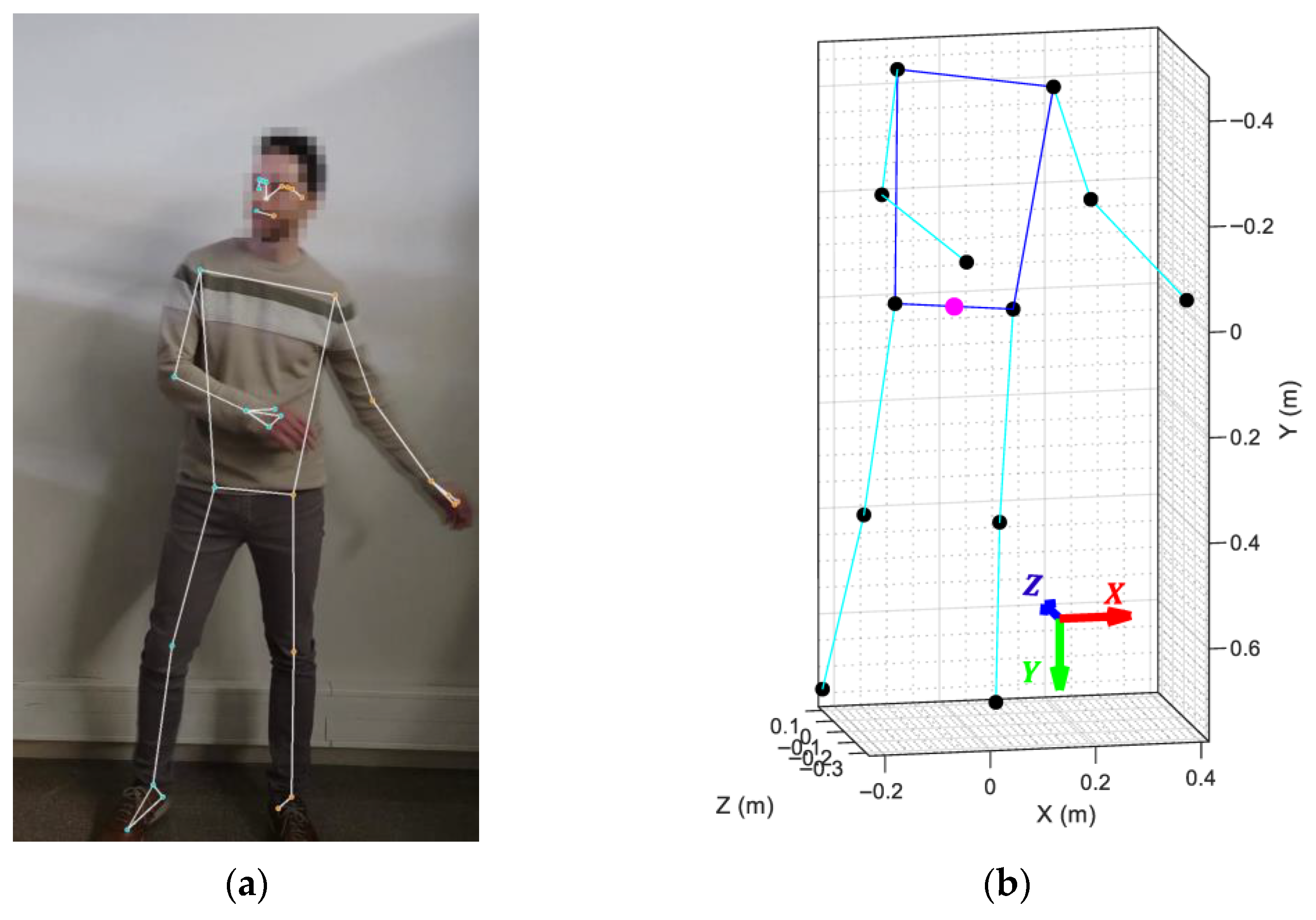
According to the MediaPipe documentation, the world coordinates of the key landmarks are expressed in meters, with the origin of the coordinate system located at the midpoint of the hips. The default coordinate convention of the skeletal mesh defines the X-axis as width, the Y-axis as height, and the Z-axis as depth. It is important to acknowledge that accurately determining the physical dimensions of an individual from a single two-dimensional image is not feasible. Consequently, the world landmark coordinates estimated by the MediaPipe BlazePose framework represent only an approximation of the actual body size and may not precisely reflect real-world measurements. Nevertheless, this limitation is not critical to the present study, as the analysis focuses primarily on the angular relationships between joints rather than on absolute body dimensions. An example of a skeletal mesh generated by the MediaPipe framework is shown in Figure 4.
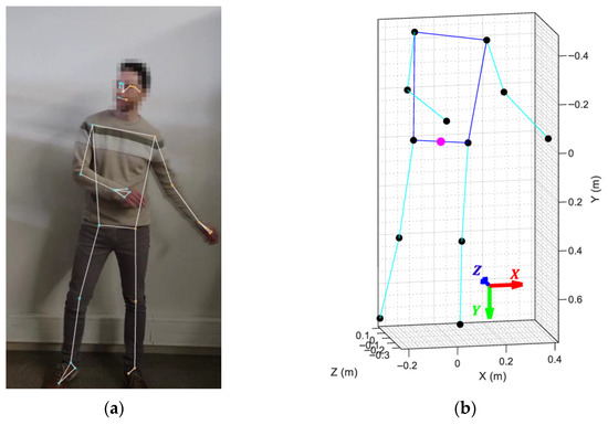
Figure 4.
MediaPipe framework output: (a) projection of the articulations and links over the original dancer’s picture; (b) 3D skeletal mesh retrieved by MediaPipe showing the limbs (cyan lines), joints (black dots), and torso (blue lines) of the detected body. The magenta dot marks the origin of the coordinate system.
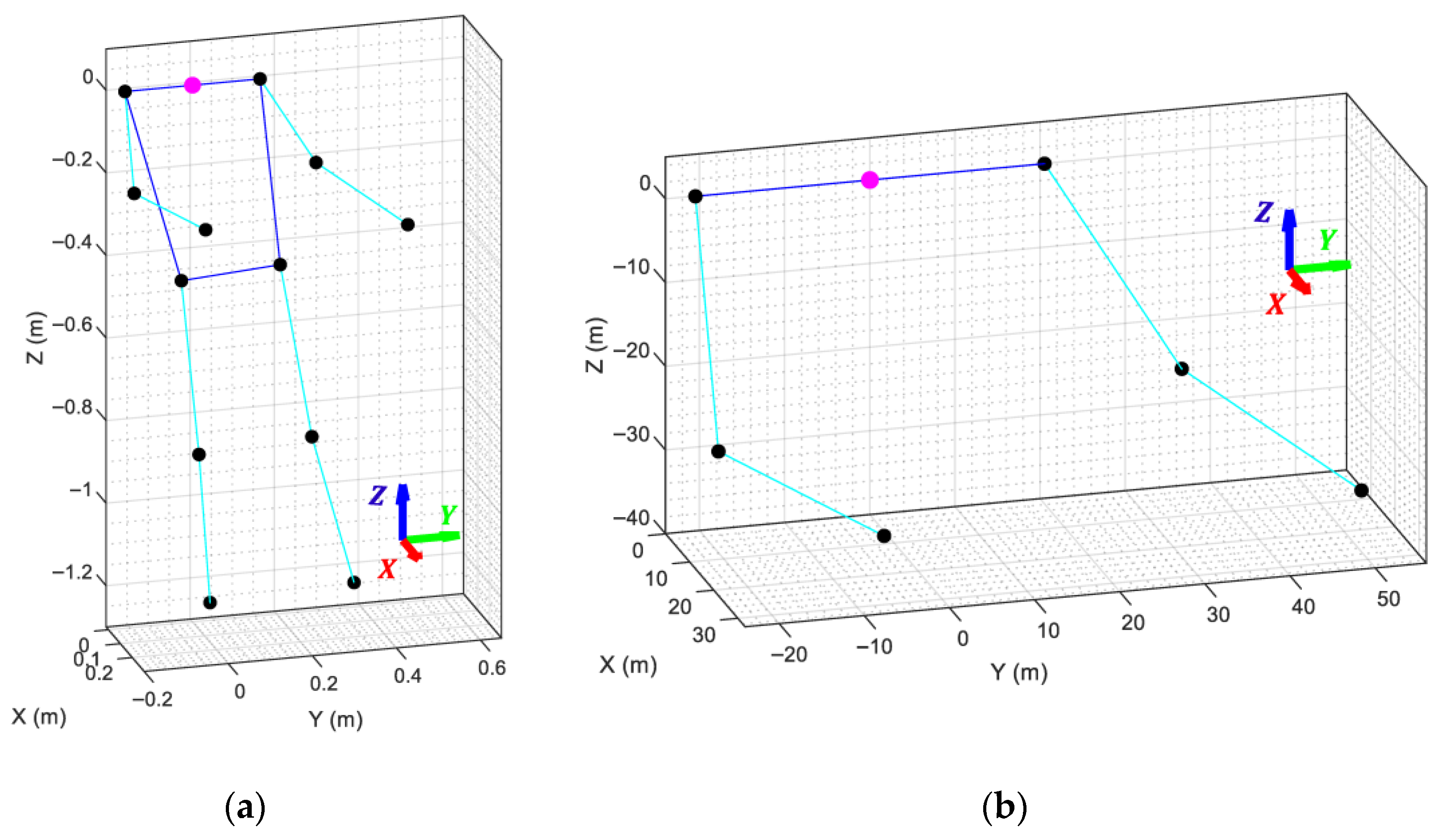
To enable a proper comparison with the VRM, it is first necessary to establish a common coordinate origin, orientation, and scale between both models. This process begins by subtracting the midpoint of the shoulders from all landmark coordinates, effectively shifting the origin of the skeletal mesh to the shoulder center. Next, the skeletal mesh is rotated around this new origin so that the torso faces forward, the back becomes parallel to the Z-axis (pointing upwards), and the shoulders are parallel to the Y-axis (Figure 5a).
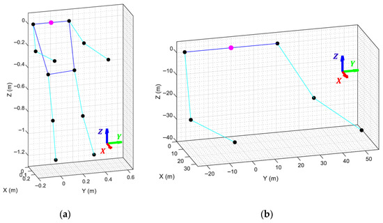
Figure 5.
MediaPipe skeletal mesh, with its coordinate system marked with a magenta dot, after: (a) shifting the coordinate origin to the shoulder midpoint and aligning its orientation to match the orientation of the VRM; (b) adjusting the arm lengths to match the dimensions of the APR robot arms.
This rotation is required because the coordinate system generated by MediaPipe is defined relative to the camera’s point of view, which differs from the robot’s reference frame. Without this alignment, even identical poses would appear geometrically incorrect. Aligning the skeletal mesh with the VRM ensures that both share the same spatial orientation, allowing the minimization algorithm to correctly interpret positional differences as actual arm movements rather than coordinate frame discrepancies.
Finally, the lengths of the shoulders, left arm, and right arm of the MediaPipe skeletal mesh are scaled to match the physical dimensions of the APR robot, while the remaining landmarks are discarded since they are irrelevant to arm motion (Figure 5b). This step guarantees that the arms of both models share identical proportions and coordinate origins, ensuring that at least one combination of VRM joint angles can produce a perfect spatial overlap between the two models.
3.2. Virtual Robot Model (VRM)
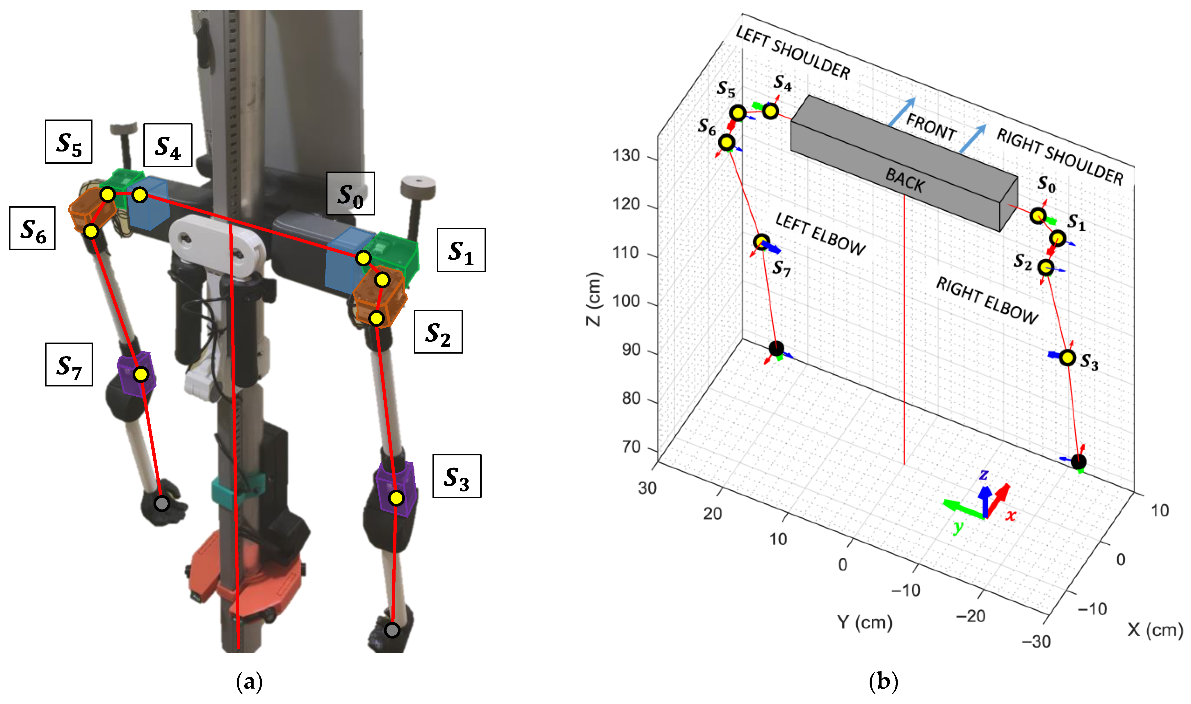
A human arm is connected to the shoulder using a ball-joint-socket, where a single articulation provides three degrees of freedom enabling simultaneous rotations around the X, Y, and Z axes. To replicate this level of mobility, the APR robot’s shoulder joint is implemented using three chained digital servomotors, effectively emulating the same three DoF of a human shoulder. Additionally, an extra servomotor is incorporated in each arm to reproduce the flexion and extension of the elbow (Figure 6a).
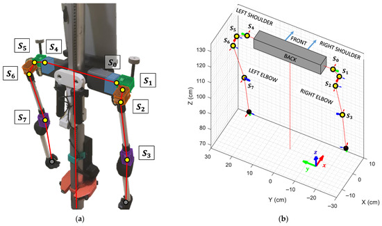
Figure 6.
Distribution, connections and labeling of the articulations controlling the robot’s arms: (a) Real APR robot, with digital servomotors highlighted in different colors for clarity; (b) Virtual Robot Model, with each articulation highlighted using a yellow circle along its local X, Y, and Z axes. The active rotation axis is indicated with a thicker arrow.
Although the APR robot possesses the same number of degrees of freedom (DoF) as a human arm, its kinematics are inherently more complex, as the order of applied rotations directly affects the position of the end-effector (wrist). The VRM is employed to compute the precise coordinates of the elbow and wrist joints for a given set of servomotor angles. A visual representation of the VRM, viewed from the rear of the APR, is shown in Figure 6b, where each servomotor is represented by a yellow circle, and the X (red), Y (green), and Z (blue) axes of each servo are indicated by arrows. The rotation axis of each servo is highlighted using a thicker arrow.
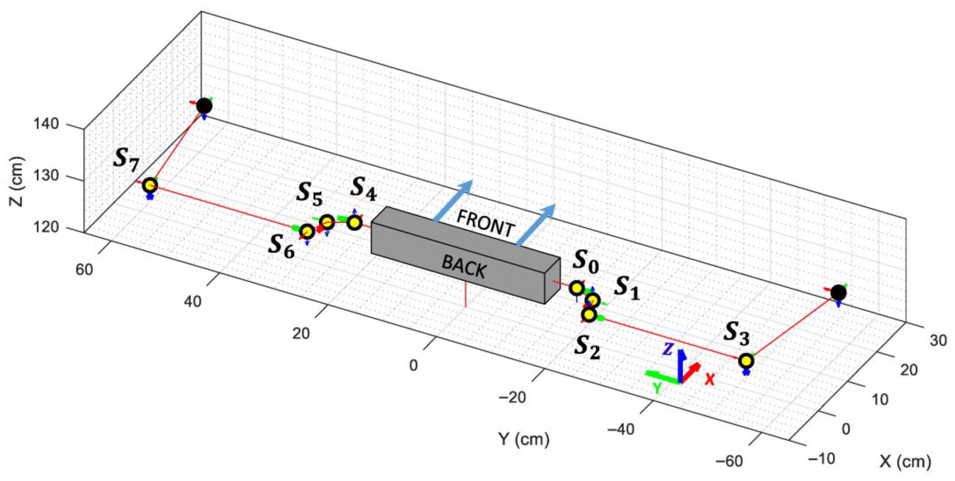
The VRM joints are designed taking into consideration the rotation direction and initial angle of the servomotors used to drive the APR’s arms, ensuring that both models will reach the same pose when given the same angle value. The parameters of the VRM used for the right and left arms are provided in Table 2 and Table 3, respectively, indicating the position and orientation offsets between consecutive articulations, the joint name, and the axis that can be rotated in each articulation. Finally, Figure 7 shows the VRM when all angles are set to 0 radians.

Table 2.
VRM parameters for the right arm.

Table 3.
VRM parameters for the left arm.
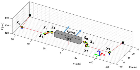
Figure 7.
Representation of the Virtual Robot Model when all angles are set to 0 radians and the servo’s offset are taken into consideration. Each articulation is highlighted using a yellow circle along its local X, Y, and Z axes. The active rotation axis is indicated with a thicker arrow.
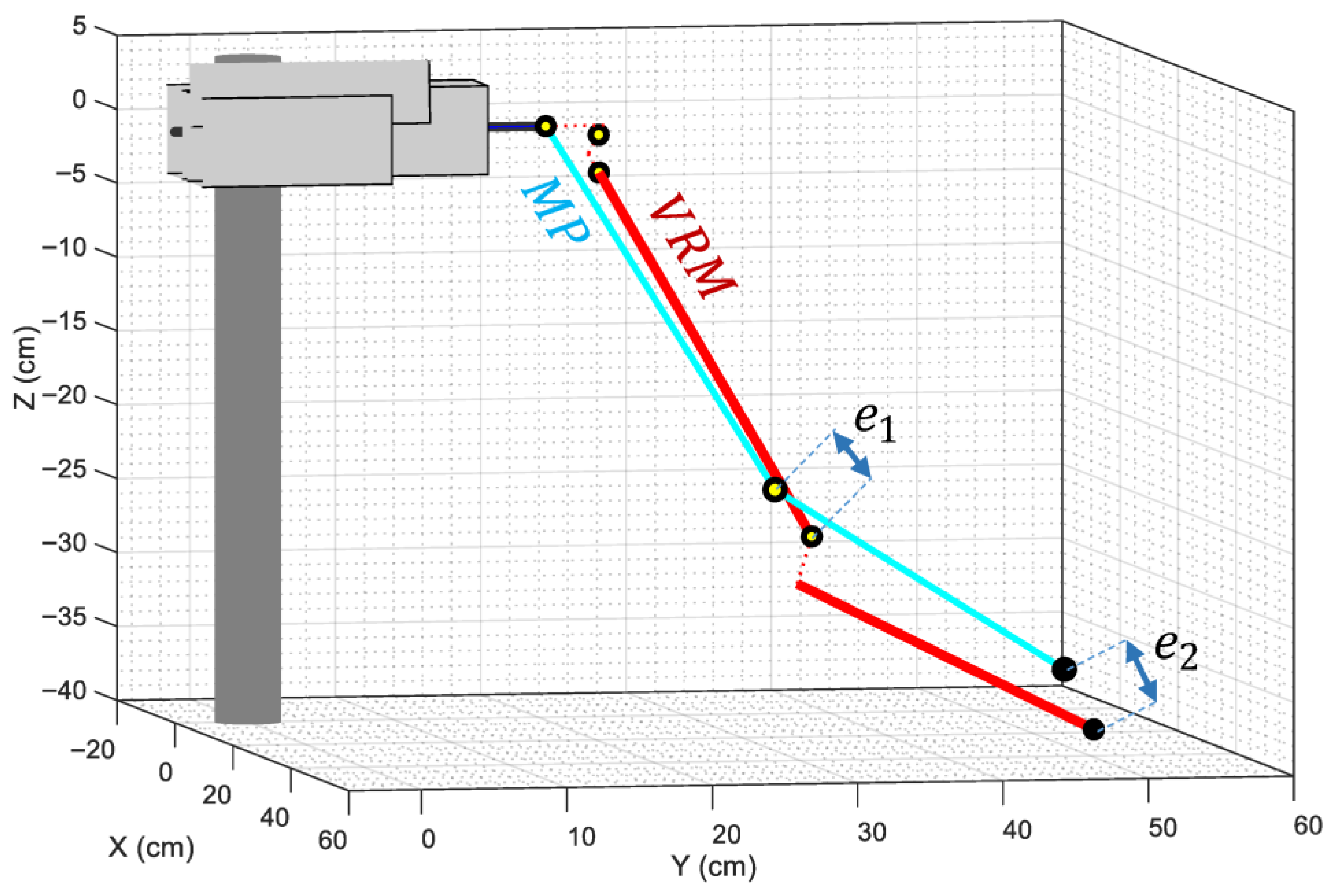
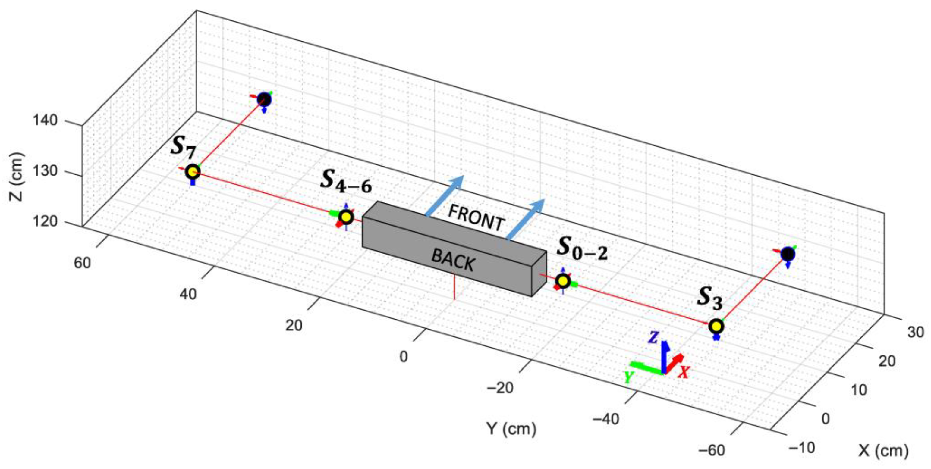
Since the MediaPipe skeletal mesh assumes that the shoulder of a person is composed of a ball-and-socket joint, no offsets can be added to mimic the distances introduced by the servos that conform the mechanical structure of the arms of the humanoid robot. In order to ensure that the distances between the elbow and wrist coordinates of both models can be mathematically reduced to zero, both models need to be identical in size and shape. Figure 8 shows that it is not possible to reduce those distances to zero unless the offsets introduced by the servos are omitted, as they do not exist in a human shoulder, so they are not modeled by the MediaPipe framework. For this purpose, a simplified VRM is created, where the offset of the servos that compose each shoulder of the APR robot (servos 0, 1 and 2 of the right shoulder, and servos 4, 5 and 6 of the left shoulder) is set to zero.
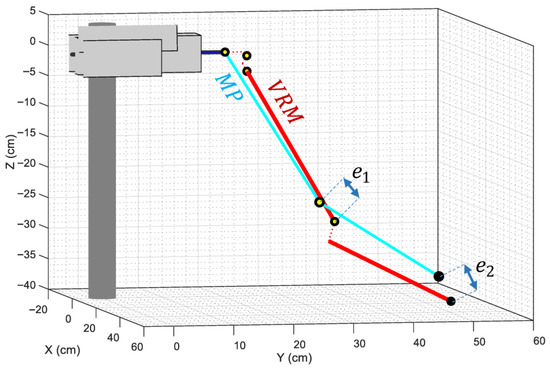
Figure 8.
Comparison between the left arm of the MediaPipe (cyan lines) and the VRM (red lines) models when the offsets introduced by the robot’s servos are taken into consideration. The dotted red lines indicate the distances omitted in the simplified VRM. Labels and depict the minimum distances obtained when adjusting the angles of the articulations to minimize the distance between the elbow and wrist coordinates of both models.
The visual representation of the VRM used in this paper is presented in Figure 9, showing an overlap between the shoulder joints but keeping the connections between them in order to replicate the mobility of the robot’s arms.
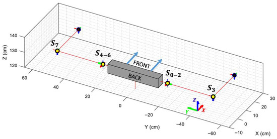
Figure 9.
Depiction of the simplified Virtual Robot Model when all angles are set to 0 radians and the servo’s offsets are omitted. Each articulation is highlighted using a yellow circle along its local X, Y, and Z axes. The active rotation axis is indicated with a thicker arrow.
3.3. Person-to-Robot Angle Minimization Function
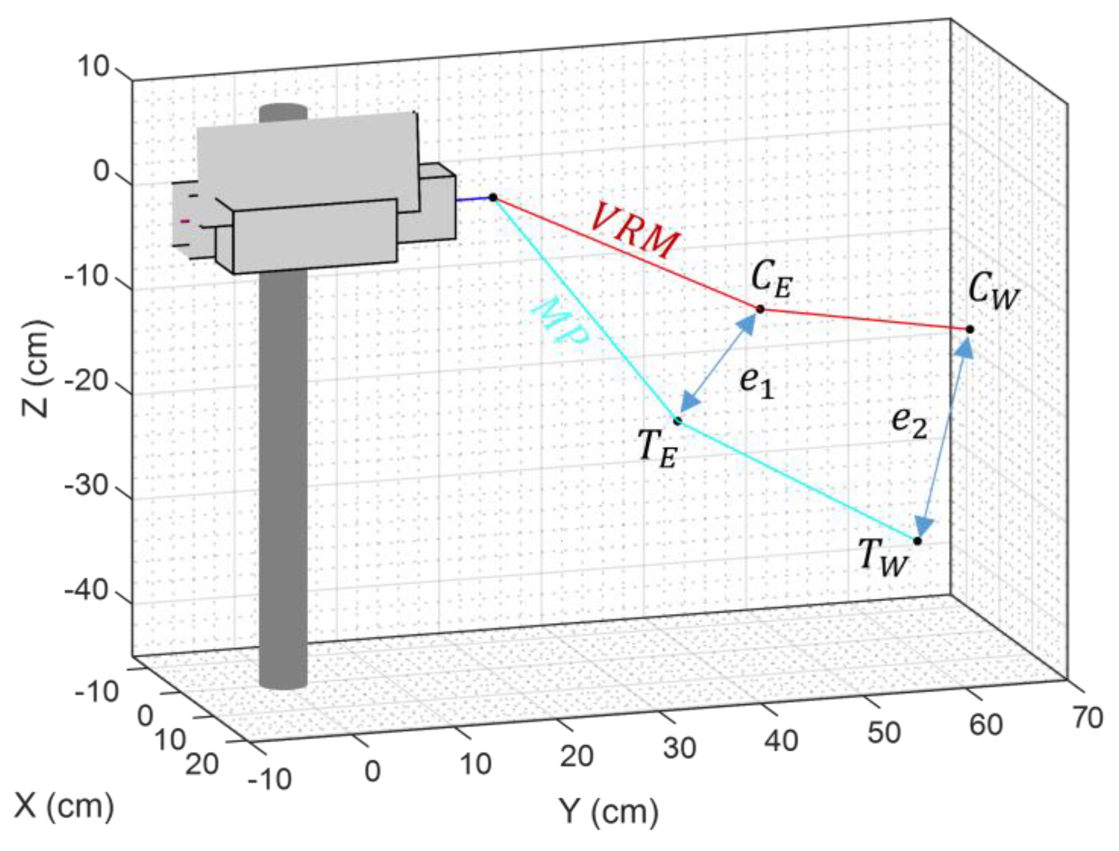
The function used to compute the joint angles of the humanoid robot is the constrained nonlinear multivariable minimization function fmincon from Matlab. This function is used to iteratively adjust the VRM arms of the robot (represented as red lines in Figure 10) until they overlap with the arms of the MediaPipe skeletal mesh (represented as cyan lines in Figure 10). The parameters of the minimization function are presented in Table 4. The cost function of the minimization algorithm is computed taking into consideration the distance between current elbow position and the target elbow position , and the distance between the current wrist position and the target wrist position . The equations defining the cost function are provided in Equations (1)–(3). The final cost function doubles the weight of to prioritize the accuracy of the elbow position, as this was found to produce superior visual fidelity of the matching.
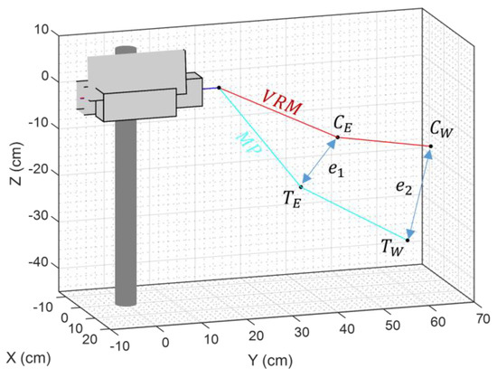
Figure 10.
Depiction of the distances used as input values for the minimization algorithm’s cost function. The labels used in this representation are current elbow position (), current wrist position (), target elbow position (), and target wrist position ().

Table 4.
Summary of the parameters established for the Matlab fmincon function.
The output of this minimization function is a set of servomotor angles which enable the APR robot to reproduce the dancer’s pose in a frame of the video.
3.4. Person-to-Robot Angle Conversion Procedure
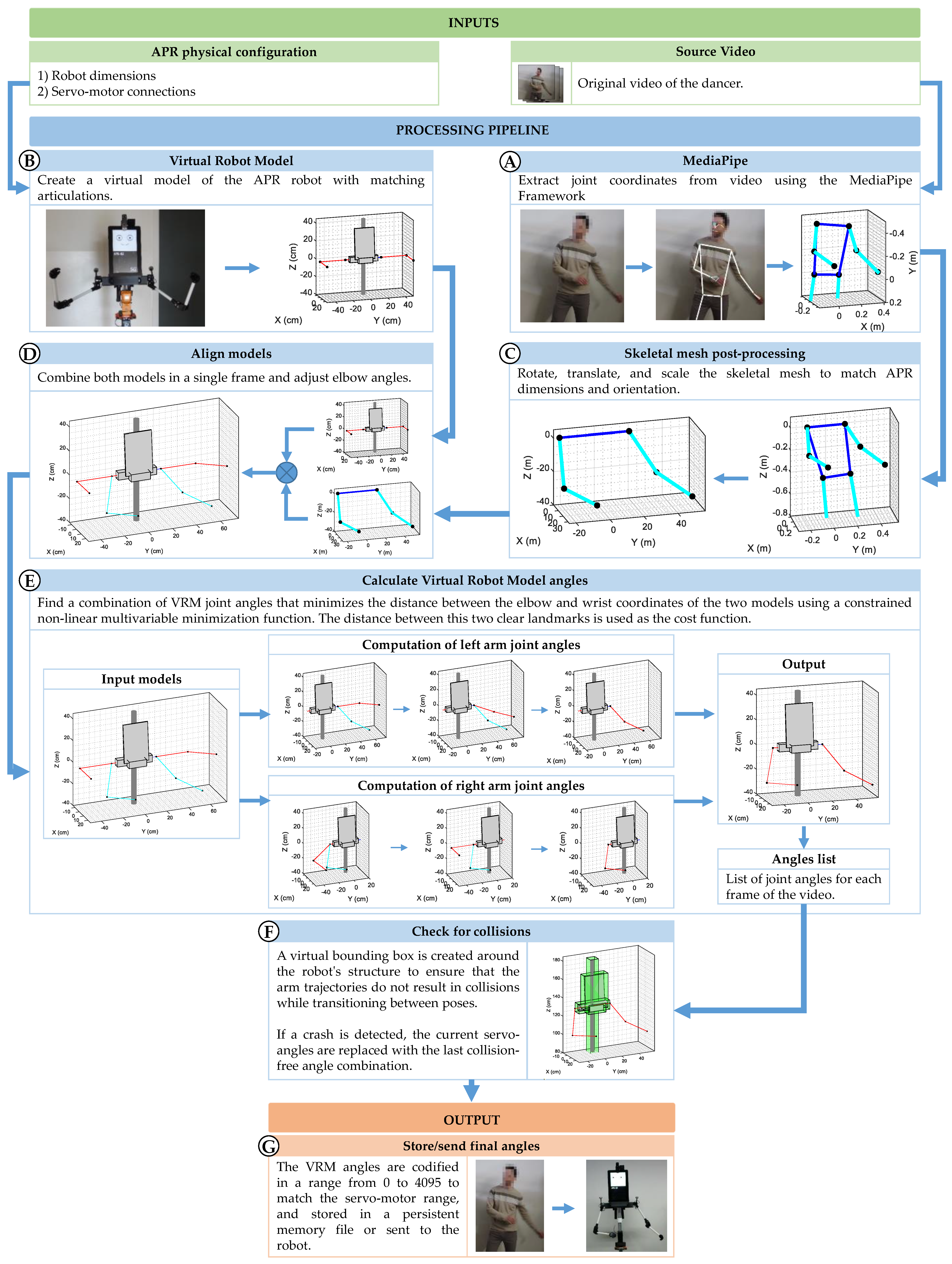
The procedure implemented to generate the arm motion control commands for the APR robot —intended to replicate the movements performed by the dancer—begins with the extraction of joint coordinates from the original video using the MediaPipe framework (Figure 11A). Simultaneously, the robot’s dimensions and servomotor configuration are used to construct a Virtual Robot Model (Figure 11B). This model is essential for determining how the robot’s arms will respond to the different servomotor angles specified in the motion commands.
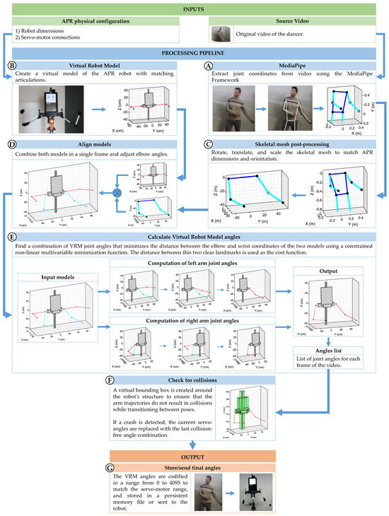
Figure 11.
Flux diagram of the process followed to calculate and the angles for the digital servomotors of the APR robot to reproduce the arm’s movements of a dancer from a video.
Then, the skeletal mesh coordinates are reoriented, scaled, and translated to match the APR robot’s dimensions (Figure 11C), ensuring that both the MediaPipe skeletal mesh and the VRM representation share a common coordinate system and scale. The result is a virtual representation of the dancer’s pose that is spatially aligned with the VRM. Since the elbow joint of each arm provides only one degree of freedom (DoF), its angle is directly computed from the geometric angle between the upper arm and forearm in the MediaPipe model (Figure 11D). Then, the joint angles of the skeletal mesh are transferred to the joints of the VRM (Figure 11E) using the cost function and minimization function described in the previous section.
Since the VRM of the APR includes the entire robot body, each structural component is enclosed within a collision-detection bounding box (shown as green boxes in Figure 11F). This procedure allows the system to evaluate whether the trajectory of the arms would result in a collision with the robot’s own structure while transitioning between poses (Figure 11F). At this point, additional processing steps could be added to further improve the trajectory followed by the arms in order to achieve smoother, human-like movement [78]; nevertheless, and since the objective of this work is to replicate a robot dance, this step is not considered. Finally, the list of joint robot angles computed with the procedure are stored to reproduce the movements of the human dancer (Figure 11G).
4. Results
This section presents the results obtained when using the proposed method to recreate a 28 s human dance with the APR robot. The dance was recorded at a resolution of 1080 × 1920 pixels and a frame rate of 30 frames per second, resulting in a total of 848 frames. The detailed analysis of the results obtained when using MediaPipe’s pose estimation framework to extract 3D coordinates of the joints of the dancer from the 2D video frames is presented in Section 4.1. Section 4.2 evaluates the performances of the nonlinear minimization function used to compute the angles of the servomotors of the APR robot. Finally, Section 4.3 presents the results obtained when the robot dance is reproduced on the physical APR robot
4.1. Pose Detection Results
To evaluate the robustness and reliability of MediaPipe’s pose detection algorithm, each video frame was manually inspected to verify whether the extracted skeletal mesh accurately matched the actual pose of the dancer. There are two main problems that could be expected during the skeletal mesh extraction process: (i) occlusion of body parts due to the dancer’s position, and (ii) difficulties identifying the body of the dancer and its extremities in the video.
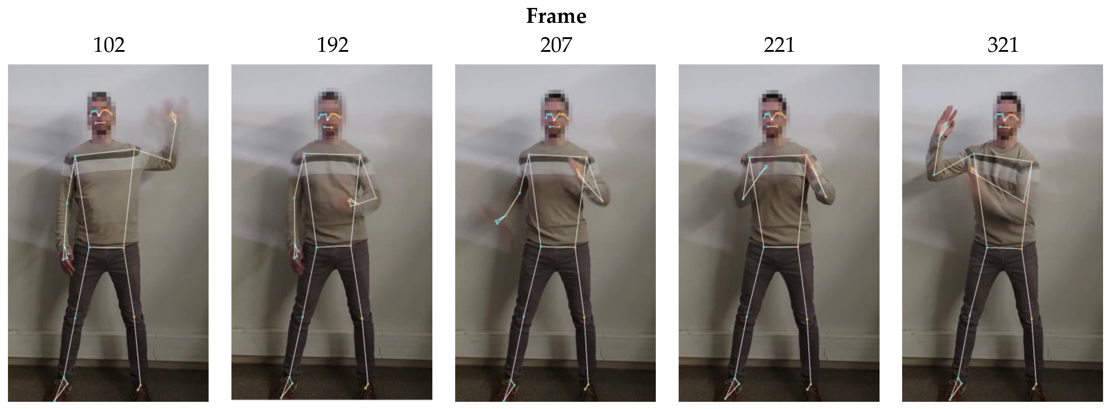
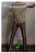
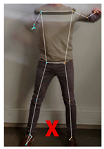
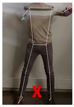
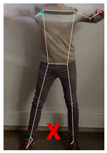
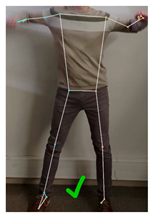
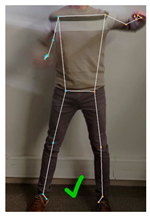
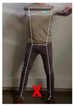
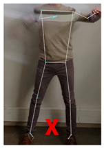
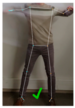
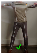
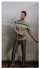
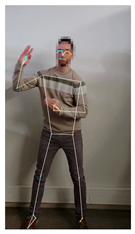
Since the dance for this work was performed with the dancer always facing the camera, occlusion did not occur during the recording of the video; nevertheless, and due to the high-speed motion of the arms during the robot-like dance, frames where the dancer’s arms appear blurry were quite common within the footage. A set of blurry, challenging non-consecutive frames where MediaPipe was successful at extracting the skeletal mesh of the dancer is provided in Figure 12.
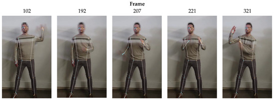
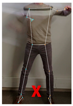
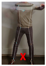
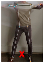
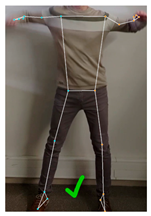
Table 5 shows that only 7 out of the 848 video frames exhibited incorrect pose estimation when Model Complexity was set to 1 (default value). The set of images presented in the second row of Table 6 show a sequence of three consecutive frames (frames 481 to 483) in which the algorithm was unable to detect the correct position of the dancer’s right arm. For context, frames 480 and 484 are also included to show the frames immediately preceding and following the erroneous detections.

Table 5.
Summary of the MediaPipe’s results for different problematic frames relative to the value for the Model Complexity parameter: ✓ means correct and ✕ incorrect pose estimation results.

In order to evaluate the impact that using different Model Complexity values for the MediaPipe pose estimation algorithm, the same video was analyzed after setting this parameter to 0, 1, and 2. Results showed that, when set to 0, the number of frames in which MediaPipe was unable to determine the right pose of the dancer increased to 17, compared to the 7 frames with erroneous detections that occurred when this parameter was set to 1. On the other hand, when increasing the Model Complexity to 2, the number of frames with erroneous detections dropped down to 6. This information is summarized in Table 5. Additionally, a set of comparative frames analyzed with different Model Complexity values is presented in Table 6.
As could be expected, increasing the Model Complexity improved detection accuracy; however, this also impacted the video processing time. Table 7 presents a comparison of processing times for the same video when MediaPipe’s Model Complexity is set to 0, 1, and 2. These results evidenced that the average time required to process a single frame increased from 63.83 ms to 72.06 ms when the Model Complexity parameter is changed from 0 to 1. This increase becomes even more noticeable with Model Complexity set to 2, where the average time per frame rises by approximately 134.63%.

Table 7.
Execution time and erroneous pose detection results obtained when changing the Model Complexity setting of the MediaPipe’s pose estimation algorithm.
The results obtained during the study of the MediaPipe’s pose estimation algorithm show that, despite being faster, setting the Model Complexity parameter to 0 largely increases the number of frames in which the pose of the dancer is not detected properly. On the other hand, complexity model 1 increases the time required to process a video around 12% but halves the number of erroneous pose detections. Finally, setting the Model Complexity parameter to 2 provides the best pose-estimation results but does so at the expense of taking over twice the time to process each frame.
4.2. Angle Extraction Results
To evaluate the accuracy of converting joint coordinates to servomotor angles, the average distance between the original MediaPipe skeletal joint positions and the corresponding positions computed using the VRM was calculated. This computation shows the errors introduced by the minimization algorithm used to determine the servo angles required to replicate arm movements. Figure 13 shows the evolution of the cost function relative to the frame analyzed. The positioning error results are summarized in Table 8.

Figure 13.
Visual representation of the positioning error between the arms of the MediaPipe skeletal mesh and the arms of the Virtual Robot Model. Some frames have been labeled (from A to E) for further comparison during the results section.

Table 8.
Distance between the MediaPipe skeletal mesh and VRM joints after using a minimization algorithm to calculate the VRM joint angles.
Analyzing the positioning error results described in Table 8, it becomes clear that the minimization algorithm was capable of finding an adequate set of servomotor angles that successfully recreated the skeletal mesh pose, achieving an average positioning error of 0.8 mm and 0.83 mm for the left and right arms, respectively. Additionally, it can be observed that the wrist positioning error is three times larger than the elbow error. This is to be expected due to the definition of the cost function, in which more weight was given to the elbow positioning error to improve the similarity of the arm’s pose.
Results also show that both arms present similar positioning errors, with an average difference of only 0.03 mm between them. Using the fmincon minimization function to calculate the best set of angles for both arms to reduce the distance between key landmarks provided remarkably accurate results, as the maximum discrepancy found between the skeletal mesh and the VRM was always below 2.5 cm for any of the joints, a positioning error that should be imperceptible to the human eye when translated to the real robot.
Figure 14 shows the evolution of the number of iterations taken by the minimization function before concluding the search in each frame. The average results are also provided in Table 9. On average, the fmincon algorithm required 8.16 and 6.73 iterations to find the appropriate set of servomotor angles for the left and right arms, respectively. In all frames, the stopping criterion was that all constraints were satisfied, and the size of the current step was smaller than the value of the step size tolerance. This indicates that, although a better solution may exist, the current solution was within the limits of allowed tolerance limits, and the improvements made in each step had become smaller than the user-defined step size tolerance of 0.001. It can also be observed that in some frames, a single iteration was enough to conclude the search. This can be explained by the existence of consecutive frames in which the dancer did not alter his position. Finally, the maximum number of iterations (22 and 20 for the left and right arms, respectively) indicates that the minimization algorithm never reached the limit number of iterations before giving up the search.

Figure 14.
Number of iterations performed by the fmincon algorithm before concluding the search for the left (red line) and right (blue line) servomotor angles. Some frames are labeled (from A to E) for further comparison during the results section.

Table 9.
Summary of the number of iterations spent by the fmincon algorithm before concluding the search of the left and right arm’s angles.
4.3. Robot Pose Results
This last section discussed the perception of the robot dance performed by the humanoid robot when sequentially executing the calculated servomotor angles. Since the exact coordinates of the real robot joints cannot be obtained, this assessment is performed through a set of visual comparisons, presented in Table 10. From the five frames displayed in Table 10, frames 324, 516 and 642 (labeled B, D, and E, respectively) were randomly selected, while frames 1 (A) and 450 (C) were manually selected. In this case, frame 1 was included because the minimization algorithm had no prior knowledge of the joint angles, resulting in a large position difference between the joint coordinates of the VRM and the MediaPipe skeletal mesh. Finally, frame 450 was chosen as a representative frame with above-average positioning error.

Table 10.
Comparison between frames 1, 324, 450, 516, and 642 showing: (a) the real dancer’s position along with the key landmark coordinates detected using MediaPipe (joint descriptions are on Figure 1 and Table 1); (b) the virtual robot model (VRM) after using the minimization algorithm to determine its joint angles; (c) the final pose of the robot after executing the corresponding arm motion commands.
In order to provide a comprehensive visual comparison of the final result, each one of the selected frames is displayed along with the skeletal mesh retrieved by MediaPipe (Table 10-Human dancer), the resulting VRM robot after setting the servomotor angles to the ones calculated using the minimization algorithm (Table 10-VRM), and a picture of the robot recreating that pose (Table 10-APR robot).
It is worth mentioning that the images of the robot in Table 10 were taken individually, as recording a video of the robot while performing the entire dance, and then locating the exact frames depicted in rows A and B of Table 10 would prove extremely difficult and could lead to inaccurate pose comparisons. For this reason, the procedure followed to extract the robot images presented in Table 10 sends the computed angles of each frame to the VRM, taking a picture of the resulting pose.
Although the match is not exact, the robot’s pose is sufficiently similar to the dancer’s that the current dance step can be easily recognized. However, a noticeable discrepancy can be observed in frame 516, where the dancer’s right wrist is positioned below the shoulder level, while in the VRM, the right wrist appears clearly above it.
To identify the source of this mismatch, the skeletal mesh for this frame was analyzed. It was found that the MediaPipe pose estimation algorithm interpreted the dancer as if his body was slightly leaning forward. As a result, after the mesh was straightened to match the upright posture of the robot, the arms’ pitch increased, altering their perceived orientation.
When comparing the VRM (Table 10) to the actual robot pose (Table 10), the major difference can also be observed in frame 516. In this case, the differences between the structure of the robot and its simplified VRM are more noticeable, as the connection between the servos of the real robot changes the origin of the left and right arm’s, placing them slightly below the shoulders; an effect that is not considered in the VRM robot.
Finally, an analysis of the results across all frames reveals that the position of the arms consistently appears slightly tilted downward. This error was traced to looseness in some of the physical structure’s links, which introduces a positional offset when the robot operates against gravity. Nevertheless, the dancer’s pose remains clearly recognizable when reproduced by the APR robot.
5. Conclusions
This paper presented a procedure that allows a robot to recreate a dance from a 2D video using the MediaPipe BlazePose framework. In this first approach to this problem, the scope of the paper was limited to offline recreation the arm movements of a human dancer, recorded in a video.
Due to the differences between the biomechanics of a human shoulder compared to the mobility of the APR robot shoulder, it was not possible the direct calculation of the servomotor angles that would recreate the pose of the dancer. To obtain this information, a simplified Virtual Robot Model (VRM) that recreates the mobility of the arms of the robot from the servomotor distribution was created. Then, the skeletal mesh retrieved by the MediaPipe BlazePose framework was adapted to match the dimensions and orientation of the VRM. After that, a minimization function was used to iteratively adjust the angles of the servomotors of the VRM until the distance between key joints of the MediaPipe skeletal mesh and the VRM were minimum.
After testing the proposed procedure in a real case-scenario, it was concluded that the MediaPipe BlazePose framework was capable of generating 3D coordinates from 2D frames of a video although some inaccuracies were obtained when the image of the dancer’s arms appears blurry in the footage. A good case example of this error was observed in frame number 516 (Table 10), where MediaPipe determined that the dancer was leaning forward, while the real dancer kept his back completely straight.
As a summary, only 7 frames of the 848 frames of the video showed dissimilarities large enough to be considered that the pose of the dancer would not be recognizable, achieving a success rate of 99.17% for the default Model Complexity (set to 1) of the MediaPipe framework. However, even with Model Complexity set to 0, the MediaPipe algorithm required a minimum of 55 ms to process each video frame, making this procedure unsuitable for real-time use to replicate the dance, which would require a maximum frame time of 33 ms for a real-time feed at 30 frames per second.
Finally, the conclusion is that the humanoid robot was capable of replicating the movement of the dancer’s arms featuring a robot dance but was unable to follow the original rhythm of the dance due to acceleration limitations of its actuators. A video clip showing the maximum performance of the robot dance is provided as Supplementary Material.
This work has been limited to the application of the MediaPipe BlazePose framework in the analysis of one dance and one dancer wearing a single outfit. However, there is a rich scientific body of literature proving the versatility of the application of the framework [79,80]. Additionally, one advantage of this framework is the availability of a MediaPipe Model Maker which is able to retrain the entire machine learning model of the framework using a transfer learning technique [81] that retains the existing model logic. Consequently, less data and less computational effort is required to retrain the model, approximately 100 images for each newly trained class.
Future work on this project require improving the time required to adjust the VRM of the humanoid robot by implementing a direct Deep Learning approach [56] instead of a minimization approach. The objective must be to achieve real-time performances rather than matching accuracy. This achievement will enable the creation of robot-like dance choreographies synchronized to the music beat [82,83] and the creation of cooperative dances with human counterparts [71]. Additionally, this application must be extended to different dancers with different physical constitutions and other dancing styles to assess the general reliability of the proposed implementation for replicating the body-pose of a dancer with a humanoid robot.
Supplementary Materials
The following supporting information can be downloaded at: https://www.mdpi.com/article/10.3390/robotics14110153/s1, Video S1: Robot dance video clip.
Author Contributions
Conceptualization, J.P., E.C. and D.M.; methodology, E.C.; software, E.C. and D.M.; validation, J.P.; formal analysis, E.C. and D.M.; investigation, D.M. and E.C.; resources, J.P.; data curation, E.C.; writing—original draft preparation, D.M. and E.C.; visualization, E.C. All authors have read and agreed to the published version of the manuscript.
Funding
This research received no external funding.
Data Availability Statement
Data is contained within the article and Supplementary Material.
Conflicts of Interest
The authors declare no conflicts of interest. The funders had no role in the design of the study; in the collection, analyses, or interpretation of data; in the writing of the manuscript; or in the decision to publish the results.
References
- Minato, T.; Shimada, M.; Ishiguro, H.; Itakura, S. Development of an Android Robot for Studying Human-Robot Interaction. In Proceedings of the Innovations in Applied Artificial Intelligence, Graz, Austria, 9 July 2004; Orchard, B., Yang, C., Ali, M., Eds.; Springer: Berlin, Germany, 2004; pp. 424–434. [Google Scholar]
- Lee, D.; Lee, T.; So, B.-R.; Choi, M.; Shin, E.-C.; Yang, K.; Baek, M.; Kim, H.-S.; Lee, H.-G. Development of an Android for Emotional Expression and Human Interaction. In Proceedings of the 17th World Congress the International Federation of Automatic, Control, Seoul, Republic of Korea, 6 July 2008; pp. 4336–4337. [Google Scholar]
- Lee, K.W.; Kim, H.-R.; Yoon, W.C.; Yoon, Y.-S.; Kwon, D.-S. Designing a Human-Robot Interaction Framework for Home Service Robot. In Proceedings of the 2005 IEEE International Workshop on Robot and Human Interactive Communication, Nashville, TN, USA, 13 August 2005; pp. 286–293. [Google Scholar]
- Muthugala, M.A.V.J.; Jayasekara, A.G.B.P. MIRob: An Intelligent Service Robot That Learns from Interactive Discussions While Handling Uncertain Information in User Instructions. In Proceedings of the 2016 Moratuwa Engineering Research Conference (MERCon), Moratuwa, Sri Lanka, 5 April 2016; pp. 397–402. [Google Scholar]
- Vasquez, H.A.; Vargas, H.S.; Sucar, L.E. Using Gestures to Interact with a Service Robot Using Kinect 2. Res. Comput. Sci. 2015, 96, 85–93. [Google Scholar] [CrossRef]
- Lin, C.-J.; Li, T.-H.S.; Kuo, P.-H.; Wang, Y.-H. Integrated Particle Swarm Optimization Algorithm Based Obstacle Avoidance Control Design for Home Service Robot. Comput. Electr. Eng. 2016, 56, 748–762. [Google Scholar] [CrossRef]
- Palacín, J.; Clotet, E.; Martínez, D.; Martínez, D.; Moreno, J. Extending the Application of an Assistant Personal Robot as a Walk-Helper Tool. Robotics 2019, 8, 27. [Google Scholar] [CrossRef]
- Chaichaowarat, R.; Prakthong, S.; Thitipankul, S. Transformable Wheelchair–Exoskeleton Hybrid Robot for Assisting Human Locomotion. Robotics 2023, 12, 16. [Google Scholar] [CrossRef]
- Shimada, M.; Yoshikawa, Y.; Asada, M.; Saiwaki, N.; Ishiguro, H. Effects of Observing Eye Contact between a Robot and Another Person. Int. J. Soc. Robot. 2011, 3, 143–154. [Google Scholar] [CrossRef]
- Rubies, E.; Palacín, J.; Clotet, E. Enhancing the Sense of Attention from an Assistance Mobile Robot by Improving Eye-Gaze Contact from Its Iconic Face Displayed on a Flat Screen. Sensors 2022, 22, 4282. [Google Scholar] [CrossRef]
- Kondo, Y.; Takemura, K.; Takamatsu, J.; Ogasawara, T. A Gesture-Centric Android System for Multi-Party Human-Robot Interaction. J. Hum.-Robot. Interact. 2013, 2, 133–151. [Google Scholar] [CrossRef]
- Huang, Z.; Ren, F.; Bao, Y. Human-like Facial Expression Imitation for Humanoid Robot Based on Recurrent Neural Network. In Proceedings of the 2016 International Conference on Advanced Robotics and Mechatronics (ICARM), Macau, China, 18 August 2016; pp. 306–311. [Google Scholar]
- Ahn, H.S.; Lee, D.-W.; Choi, D.; Lee, D.Y.; Hur, M.H.; Lee, H.; Shon, W.H. Development of an Android for Singing with Facial Expression. In Proceedings of the IECON 2011—37th Annual Conference of the IEEE Industrial Electronics Society, Melbourne, VIC, Australia, 7 November 2011; pp. 104–109. [Google Scholar]
- Becker-Asano, C.; Ishiguro, H. Evaluating Facial Displays of Emotion for the Android Robot Geminoid F. In Proceedings of the 2011 IEEE Workshop on Affective Computational Intelligence (WACI), Paris, France, 11 April 2011; pp. 1–8. [Google Scholar]
- Oh, K.-G.; Jung, C.-Y.; Lee, Y.-G.; Kim, S.-J. Real-Time Lip Synchronization between Text-to-Speech (TTS) System and Robot Mouth. In Proceedings of the 19th International Symposium in Robot and Human Interactive Communication, Viareggio, Italy, 13 September 2010; pp. 620–625. [Google Scholar]
- Mehrabian, A. Silent Messages: Implicit Communication of Emotions and Attitudes, 2nd ed.; Wadsworth Publishing Company: Belmont, CA, USA, 1981; ISBN 978-0-534-00910-6. [Google Scholar]
- Ekman, P.; Friesen, W.V. Unmasking the Face: A Guide to Recognizing Emotions from Facial Clues; ISHK: Woolooware, NSW, Australia, 2003; ISBN 978-1-883536-36-7. [Google Scholar]
- Mori, M.; MacDorman, K.F.; Kageki, N. The Uncanny Valley [From the Field]. IEEE Robot. Autom. Mag. 2012, 19, 98–100. [Google Scholar] [CrossRef]
- Kwak, S.S.; Kim, Y.; Kim, E.; Shin, C.; Cho, K. What Makes People Empathize with an Emotional Robot?: The Impact of Agency and Physical Embodiment on Human Empathy for a Robot. In Proceedings of the 2013 IEEE RO-MAN, Gyeongju, Republic of Korea, 26 August 2013; pp. 180–185. [Google Scholar]
- Kwon, D.-S.; Kwak, Y.K.; Park, J.C.; Chung, M.J.; Jee, E.-S.; Park, K.-S.; Kim, H.-R.; Kim, Y.-M.; Park, J.-C.; Kim, E.H.; et al. Emotion Interaction System for a Service Robot. In Proceedings of the RO-MAN 2007—The 16th IEEE International Symposium on Robot and Human Interactive Communication, Jeju, Republic of Korea, 26 August 2007; pp. 351–356. [Google Scholar]
- Hyung, H.; Lee, D.; Yoon, H.U.; Choi, D.; Lee, D.; Hur, M. Facial Expression Generation of an Android Robot Based on Probabilistic Model. In Proceedings of the 2018 27th IEEE International Symposium on Robot and Human Interactive Communication (RO-MAN), Nanjing, China, 27 August 2018; pp. 458–460. [Google Scholar]
- Go, D.; Hyung, H.; Lee, D.; Yoon, H.U. Andorid Robot Motion Generation Based on Video-Recorded Human Demonstrations. In Proceedings of the 2018 27th IEEE International Symposium on Robot and Human Interactive Communication (RO-MAN), Nanjing, China, 27 August 2018; pp. 476–478. [Google Scholar]
- Noma, M.; Saiwaki, N.; Itakura, S.; Ishiguro, H. Composition and Evaluation of the Humanlike Motions of an Android. In Proceedings of the 2006 6th IEEE-RAS International Conference on Humanoid Robots, Genova, Italy, 4 December 2006; pp. 163–168. [Google Scholar]
- Lin, C.-Y.; Huang, C.-C.; Cheng, L.-C. A Small Number Actuator Mechanism Design for Anthropomorphic Face Robot. In Proceedings of the 2011 IEEE International Conference on Robotics and Biomimetics, Karon Beach, Thailand, 7 December 2011; pp. 633–638. [Google Scholar]
- Hyung, H.-J.; Yoon, H.U.; Choi, D.; Lee, D.-Y.; Lee, D.-W. Optimizing Android Facial Expressions Using Genetic Algorithms. Appl. Sci. 2019, 9, 3379. [Google Scholar] [CrossRef]
- Ravignani, A.; Cook, P.F. The Evolutionary Biology of Dance without Frills. Curr. Biol. 2016, 26, R878–R879. [Google Scholar] [CrossRef]
- Laland, K.; Wilkins, C.; Clayton, N. The Evolution of Dance. Curr. Biol. 2016, 26, R5–R9. [Google Scholar] [CrossRef]
- Peng, H.; Zhou, C.; Hu, H.; Chao, F.; Li, J. Robotic Dance in Social Robotics—A Taxonomy. IEEE Trans. Hum.-Mach. Syst. 2015, 45, 281–293. [Google Scholar] [CrossRef]
- Michalowski, M.P.; Sabanovic, S.; Kozima, H. A Dancing Robot for Rhythmic Social Interaction. In Proceedings of the HRI ’07: The ACM/IEEE International Conference on Human-Robot Interaction; Association for Computing Machinery, New York, NY, USA, 10 March 2007; pp. 89–96. [Google Scholar]
- Nakaoka, S.; Nakazawa, A.; Kanehiro, F.; Kaneko, K.; Morisawa, M.; Hirukawa, H.; Ikeuchi, K. Learning from Observation Paradigm: Leg Task Models for Enabling a Biped Humanoid Robot to Imitate Human Dances. Int. J. Robot. Res. 2007, 26, 829–844. [Google Scholar] [CrossRef]
- Kaneko, K.; Kanehiro, F.; Kajita, S.; Hirukawa, H.; Kawasaki, T.; Hirata, M.; Akachi, K.; Isozumi, T. Humanoid Robot HRP-2. In Proceedings of the IEEE International Conference on Robotics and Automation, New Orleans, LA, USA, 26 April 2004; Volume 2, pp. 1083–1090. [Google Scholar]
- Xia, G.; Tay, J.; Dannenberg, R.; Veloso, M. Autonomous Robot Dancing Driven by Beats and Emotions of Music. In Proceedings of the AAMAS ’12: The 11th International Conference on Autonomous Agents and Multiagent Systems; International Foundation for Autonomous Agents and Multiagent Systems, Richland, SC, USA, 4 June 2012; pp. 205–212. [Google Scholar]
- Okamoto, T.; Shiratori, T.; Kudoh, S.; Nakaoka, S.; Ikeuchi, K. Toward a Dancing Robot with Listening Capability: Keypose-Based Integration of Lower-, Middle-, and Upper-Body Motions for Varying Music Tempos. IEEE Trans. Robot. 2014, 30, 771–778. [Google Scholar] [CrossRef]
- Ramos, O.E.; Mansard, N.; Stasse, O.; Benazeth, C.; Hak, S.; Saab, L. Dancing Humanoid Robots: Systematic Use of OSID to Compute Dynamically Consistent Movements Following a Motion Capture Pattern. IEEE Robot. Autom. Mag. 2015, 22, 16–26. [Google Scholar] [CrossRef]
- Gkiokas, A.; Katsouros, V. Convolutional Neural Networks for Real-Time Beat Tracking: A Dancing Robot Application. In Proceedings of the 18th International Society for Music Information Retrieval Conference, Suzhou, China, 24 October 2017. [Google Scholar]
- Qin, R.; Zhou, C.; Zhu, H.; Shi, M.; Chao, F.; Li, N. A Music-Driven Dance System of Humanoid Robots. Int. J. Humanoid Robot. 2018, 15, 1850023. [Google Scholar] [CrossRef]
- Güney, G.; Jansen, T.S.; Dill, S.; Schulz, J.B.; Dafotakis, M.; Hoog Antink, C.; Braczynski, A.K. Video-Based Hand Movement Analysis of Parkinson Patients before and after Medication Using High-Frame-Rate Videos and MediaPipe. Sensors 2022, 22, 7992. [Google Scholar] [CrossRef]
- Kim, J.-W.; Choi, J.-Y.; Ha, E.-J.; Choi, J.-H. Human Pose Estimation Using MediaPipe Pose and Optimization Method Based on a Humanoid Model. Appl. Sci. 2023, 13, 2700. [Google Scholar] [CrossRef]
- Zhang, Y.; Notni, G. 3D Geometric Features Based Real-Time American Sign Language Recognition Using PointNet and MLP with MediaPipe Hand Skeleton Detection. Meas. Sens. 2025, 38, 101697. [Google Scholar] [CrossRef]
- Fu, Z.; Zhao, T.Z.; Finn, C. Mobile ALOHA: Learning Bimanual Mobile Manipulation with Low-Cost Whole-Body Teleoperation. arXiv 2024, arXiv:2401.02117. [Google Scholar]
- Yasar, M.S.; Islam, M.M.; Iqbal, T. PoseTron: Enabling Close-Proximity Human-Robot Collaboration Through Multi-Human Motion Prediction. In Proceedings of the 2024 ACM/IEEE International Conference on Human-Robot Interaction, Boulder, CO, USA, 11 March 2024; ACM: Singapore, 2024; pp. 830–839. [Google Scholar]
- Kreiss, S.; Bertoni, L.; Alahi, A. PifPaf: Composite Fields for Human Pose Estimation. In Proceedings of the 2019 IEEE/CVF Conference on Computer Vision and Pattern Recognition (CVPR), Long Beach, CA, USA, 15 June 2019; pp. 11969–11978. [Google Scholar]
- Sun, K.; Xiao, B.; Liu, D.; Wang, J. Deep High-Resolution Representation Learning for Human Pose Estimation. In Proceedings of the 2019 IEEE/CVF Conference on Computer Vision and Pattern Recognition (CVPR), Long Beach, CA, USA, 15 June 2019; pp. 5686–5696. [Google Scholar]
- Bazarevsky, V.; Grishchenko, I.; Raveendran, K.; Zhu, T.; Zhang, F.; Grundmann, M. BlazePose: On-Device Real-Time Body Pose Tracking. arXiv 2020, arXiv:2006.10204. [Google Scholar]
- Lugaresi, C.; Tang, J.; Nash, H.; McClanahan, C.; Uboweja, E.; Hays, M.; Zhang, F.; Chang, C.-L.; Yong, M.; Lee, J.; et al. MediaPipe: A Framework for Perceiving and Processing Reality. In Proceedings of the 2019 IEEE/CVF Conference on Computer Vision and Pattern Recognition (CVPR), Long Beach, CA, USA, 15 June 2019. [Google Scholar]
- Google MediaPipe Solutions Guide. Available online: https://ai.google.dev/edge/mediapipe/solutions/guide (accessed on 29 July 2024).
- Bazarevsky, V.; Zhang, F. On-Device, Real-Time Hand Tracking with MediaPipe. Available online: http://research.google/blog/on-device-real-time-hand-tracking-with-mediapipe/ (accessed on 29 July 2024).
- Jeong, S.; Kook, J. CREBAS: Computer-Based REBA Evaluation System for Wood Manufacturers Using MediaPipe. Appl. Sci. 2023, 13, 938. [Google Scholar] [CrossRef]
- Güney, G.; Jansen, T.S.; Braczynski, A.K.; Rohr, M.; Dill, S.; Antink, C.H. Analyzing the Effect of Age and Gender on the Blink Reflex Using MediaPipe. Curr. Dir. Biomed. Eng. 2023, 9, 423–426. [Google Scholar] [CrossRef]
- Kompoliti, K.; Verhagen, L. (Eds.) Glabellar Reflex. Encyclopedia of Movement Disorders, 1st ed.; Academic Press: New York, NY, USA, 2010; ISBN 978-0-12-374101-1. [Google Scholar]
- Supanich, W.; Kulkarineetham, S.; Sukphokha, P.; Wisarnsart, P. Machine Learning-Based Exercise Posture Recognition System Using MediaPipe Pose Estimation Framework. In Proceedings of the 2023 9th International Conference on Advanced Computing and Communication Systems (ICACCS), Coimbatore, India, 17 March 2023; Volume 1, pp. 2003–2007. [Google Scholar]
- Zhang, W.; Li, Y.; Cai, S.; Wang, Z.; Cheng, X.; Somjit, N.; Sun, D.; Chen, F. Combined MediaPipe and YOLOv5 Range of Motion Assessment System for Spinal Diseases and Frozen Shoulder. Sci. Rep. 2024, 14, 15879. [Google Scholar] [CrossRef] [PubMed]
- Amprimo, G.; Masi, G.; Pettiti, G.; Olmo, G.; Priano, L.; Ferraris, C. Hand Tracking for Clinical Applications: Validation of the Google MediaPipe Hand (GMH) and the Depth-Enhanced GMH-D Frameworks. Biomed. Signal Process. Control 2024, 96, 106508. [Google Scholar] [CrossRef]
- Garg, S.; Saxena, A.; Gupta, R. Yoga Pose Classification: A CNN and MediaPipe Inspired Deep Learning Approach for Real-World Application. J. Ambient Intell. Humaniz. Comput. 2023, 14, 16551–16562. [Google Scholar] [CrossRef]
- Chaudhary, I.; Thoiba Singh, N.; Chaudhary, M.; Yadav, K. Real-Time Yoga Pose Detection Using OpenCV and MediaPipe. In Proceedings of the 2023 4th International Conference for Emerging Technology (INCET), Belgaum, India, 26 May 2023; pp. 1–5. [Google Scholar]
- Bora, J.; Dehingia, S.; Boruah, A.; Chetia, A.A.; Gogoi, D. Real-Time Assamese Sign Language Recognition Using MediaPipe and Deep Learning. Procedia Comput. Sci. 2023, 218, 1384–1393. [Google Scholar] [CrossRef]
- Wang, Y.; Li, R.; Li, G. Sign Language Recognition Using MediaPipe. In Proceedings of the International Conference on Computer Graphics, Artificial Intelligence, and Data Processing (ICCAID 2022), Guangzhou, China, 23 January 2022; SPIE: Washington, DC, USA, 2022; Volume 12604, pp. 807–813. [Google Scholar]
- Zick, L.A.; Martinelli, D.; Schneider de Oliveira, A.; Cremer Kalempa, V. Teleoperation System for Multiple Robots with Intuitive Hand Recognition Interface. Sci. Rep. 2024, 14, 30230. [Google Scholar] [CrossRef]
- Rhee, W.; Kim, Y.G.; Lee, J.H.; Shim, J.W.; Kim, B.S.; Yoon, D.; Cho, M.; Kim, S. Unconstrained Lightweight Control Interface for Robot-Assisted Minimally Invasive Surgery Using MediaPipe Framework and Head-Mounted Display. Virtual Real. 2024, 28, 114. [Google Scholar] [CrossRef]
- Ballantyne, G.H.; Moll, F. The Da Vinci Telerobotic Surgical System: The Virtual Operative Field and Telepresence Surgery. Surg. Clin. 2003, 83, 1293–1304. [Google Scholar] [CrossRef]
- Santos, B.; Gonçalves, G.; Pinto, V.; Ribeiro, F. Using a Dexterous Robotic Hand for Automotive Painting Quality Inspection. In Proceedings of the Thirteenth International Conference on Intelligent Systems and Applications (INTELLI 2024), Athenas, Greece, 10–14 March 2024; pp. 1–6. [Google Scholar]
- Lin, P.-C.; Lin, F.-C. Research on Interaction between Dancers’ Motion Capture and Robotic Arm. In Proceedings of the 2023 International Conference on Consumer Electronics–Taiwan (ICCE-Taiwan), PingTung, Taiwan, 17 July 2023; pp. 117–118. [Google Scholar]
- Solkar, A.; Dhingra, G.; Chavan, K.; Patil, N. Kathak Dance Movement Recognition and Correction Using Google’s Mediapipe. In Proceedings of the 2023 14th International Conference on Computing Communication and Networking Technologies (ICCCNT), Delhi, India, 6 July 2023; pp. 1–6. [Google Scholar]
- Wang, J.; Zhao, Y. Time Series K-Nearest Neighbors Classifier Based on Fast Dynamic Time Warping. In Proceedings of the 2021 IEEE International Conference on Artificial Intelligence and Computer Applications (ICAICA), Dalian, China, 28 June 2021; pp. 751–754. [Google Scholar]
- Aishwarya, V.; Babu, R.D.; Adithya, S.S.; Jebaraj, A.; Vignesh, G.R.; Veezhinathan, M. Identification of Improper Posture in Female Bharatanatyam Dancers—A Computational Approach. In Proceedings of the 2023 International Conference on Inventive Computation Technologies (ICICT), Lalitpur, Nepal, 26 April 2023; pp. 560–566. [Google Scholar]
- Kishore Kumar, A.V.; Emmadisetty, R.; Chandralekha, M.; Saleem, K. Mediapipe-Powered SVM Model for Real-Time Kuchipudi Mudras Recognition. In Proceedings of the 2024 2nd International Conference on Advancement in Computation & Computer Technologies (InCACCT), Gharuan, India, 2 May 2024; pp. 583–588. [Google Scholar]
- Cortes, C.; Vapnik, V. Support-Vector Networks. Mach. Learn. 1995, 20, 273–297. [Google Scholar] [CrossRef]
- Wang, H.; Zhao, C.; Huang, X.; Zhu, Y.; Qu, C.; Guo, W. Emotion Recognition in Dance: A Novel Approach Using Laban Movement Analysis and Artificial Intelligence. In Digital Human Modeling and Applications in Health, Safety, Ergonomics and Risk Management; Duffy, V.G., Ed.; Springer Nature: Cham, Switzerland, 2024; pp. 189–201. [Google Scholar]
- Mccormick, J.; Pyaraka, J.C. Real Robot Dance Challenge: Exploring Live and Online Dance Challenge Videos for Robot Movement. In Proceedings of the 9th International Conference on Movement and Computing, Utrecht, The Netherlands, 30 May 2024; ACM: Singapore, 2024; pp. 1–4. [Google Scholar]
- Costilla Caballero, S. NAO Robot That Imitates Human Movements Using Mediapipe. In Applied Robotics–Digitale Methoden WS2023; Groth, C., Ed.; Hochschule für Angewandte Wissenschaften Hof: Hof, Germany, 2024; pp. 11–14. [Google Scholar]
- Hong, H.; Costa, I.T.D.C.E.; Tanguy, A.; Kheddar, A.; Chen, C.-Y. A Cross-Temporal Robotic Dance Performance: Dancing with a Humanoid Robot and Artificial Life. In Proceedings of the ISEA 2024—29th International Symposium on Electronic Art, Brisbane, Australia, 30 May–2 June 2024. [Google Scholar]
- Clotet, E.; Martínez, D.; Moreno, J.; Tresanchez, M.; Palacín, J. Assistant Personal Robot (APR): Conception and Application of a Tele-Operated Assisted Living Robot. Sensors 2016, 16, 610. [Google Scholar] [CrossRef]
- Bitriá, R.; Palacín, J.; Rubies, E.; Clotet, E. Experience Embedding a Compact eNose in an Indoor Mobile Delivery Robot for the Early Detection of Gas Leaks. Appl. Sci. 2025, 15, 3430. [Google Scholar] [CrossRef]
- Palacín, J.; Rubies, E.; Clotet, E. The Assistant Personal Robot Project: From the APR-01 to the APR-02 Mobile Robot Prototypes. Designs 2022, 6, 66. [Google Scholar] [CrossRef]
- Robot VS Human VS Alien//Incredible Dance Moves Ver.4 “Dance Battle Compilations”. Available online: https://www.youtube.com/watch?v=0zdVRzjkWMU (accessed on 29 July 2024).
- Zhang, L.; Du, H.; Qin, Z.; Zhao, Y.; Yang, G. Real-Time Optimized Inverse Kinematics of Redundant Robots under Inequality Constraints. Sci. Rep. 2024, 14, 29754. [Google Scholar] [CrossRef] [PubMed]
- Ning, Y.; Sang, L.; Wang, H.; Wang, Q.; Vladareanu, L.; Niu, J. Upper Limb Exoskeleton Rehabilitation Robot Inverse Kinematics Modeling and Solution Method Based on Multi-Objective Optimization. Sci. Rep. 2024, 14, 25476. [Google Scholar] [CrossRef]
- Boukheddimi, M.; Harnack, D.; Kumar, S.; Kumar, R.; Vyas, S.; Arriaga, O.; Kirchner, F. Robot Dance Generation with Music Based Trajectory Optimization. In Proceedings of the 2022 IEEE/RSJ International Conference on Intelligent Robots and Systems (IROS), Kyoto, Japan, 23–27 October 2022; pp. 3069–3076. [Google Scholar]
- Latreche, A.; Kelaiaia, R.; Chemori, A.; Kerboua, A. Reliability and Validity Analysis of MediaPipe-Based Measurement System for Some Human Rehabilitation Motions. Measurement 2023, 214, 112826. [Google Scholar] [CrossRef]
- Dewanto, F.M.; Santoso, H.A.; Shidik, G.F. Purwanto Scoping Review of Sign Language Recognition: An Analysis of MediaPipe Framework and Deep Learning Integration. In Proceedings of the 2024 International Seminar on Application for Technology of Information and Communication (iSemantic), Semarang, Indonesia, 21–22 September 2024; pp. 451–458. [Google Scholar]
- Zhuang, F.; Qi, Z.; Duan, K.; Xi, D.; Zhu, Y.; Zhu, H.; Xiong, H.; He, Q. A Comprehensive Survey on Transfer Learning. Proc. IEEE 2021, 109, 43–76. [Google Scholar] [CrossRef]
- Yoshii, K.; Goto, M.; Okuno, H.G. Drum Sound Recognition for Polyphonic Audio Signals by Adaptation and Matching of Spectrogram Templates with Harmonic Structure Suppression. IEEE Trans. Audio Speech Lang. Process. 2007, 15, 333–345. [Google Scholar] [CrossRef]
- Tsunoo, E.; Ono, N.; Sagayama, S. Rhythm Map: Extraction of Unit Rhythmic Patterns and Analysis of Rhythmic Structure from Music Acoustic Signals. In Proceedings of the 2009 IEEE International Conference on Acoustics, Speech and Signal Processing, Taipei, China, 19–24 April 2009; pp. 185–188. [Google Scholar]
Disclaimer/Publisher’s Note: The statements, opinions and data contained in all publications are solely those of the individual author(s) and contributor(s) and not of MDPI and/or the editor(s). MDPI and/or the editor(s) disclaim responsibility for any injury to people or property resulting from any ideas, methods, instructions or products referred to in the content. |
© 2025 by the authors. Licensee MDPI, Basel, Switzerland. This article is an open access article distributed under the terms and conditions of the Creative Commons Attribution (CC BY) license (https://creativecommons.org/licenses/by/4.0/).

