Article

Research on Energy Consumption Optimization Strategies of Robot Joints Based on NSGA-II and Energy Consumption Mapping

School of Mechanical Engineering, Hebei University of Technology, Tianjin 300000, China
*
Author to whom correspondence should be addressed.
Robotics 2025, 14(10), 138; https://doi.org/10.3390/robotics14100138
Submission received: 6 January 2025 / Revised: 31 January 2025 / Accepted: 8 February 2025 / Published: 29 September 2025
(This article belongs to the Section Industrial Robots and Automation)

Abstract

Robot energy consumption is a prominent challenge in intelligent manufacturing and construction. Reducing energy consumption during robot trajectory execution is an urgent issue requiring immediate attention. In view of the shortcomings of traditional trajectory optimization methods, this paper proposes a multi-objective trajectory optimization method that combines energy consumption mapping with the NSGA-II, aiming to reduce robots’ trajectory energy consumption and optimize execution efficiency. By establishing a dynamic energy consumption model, energy consumption mapping is employed to constrain energy consumption within the robot’s workspace, thereby providing guidance for the optimization process. Simultaneously, with energy consumption minimization and time consumption as optimization objectives, the NSGA-II is utilized to obtain the Pareto-optimal solution set through non-dominated sorting and congestion distance calculation. Energy consumption mapping serves as a dynamic feedback mechanism during the optimization process, guiding the distribution of trajectory points towards low-energy-consumption regions, accelerating algorithm convergence, and enhancing the quality of the solution set. The experimental results demonstrate that the proposed method can significantly reduce robots’ trajectory energy consumption and achieve an effective balance between energy consumption and time consumption. Compared with the conventional NSGA-II normalized weighted function method in similar task scenarios, the robot can save 14.87% and 10.47% of its energy consumption, respectively. Compared with traditional methods, this method exhibits superior energy-saving performance and adaptability in complex task environments, providing a novel solution for the efficient trajectory planning of robots.

1. Introduction

With the rapid development of industrial automation and intelligence, robot technology has been increasingly applied in the manufacturing, logistics, healthcare, and service industries. However, the energy consumed by robots during task execution has increasingly become a pivotal bottleneck, limiting their broader adoption and expansion. Therefore, the pursuit of effective strategies to reduce robot energy consumption and elevate energy efficiency has become a focal point of research in both academic and industrial circles [1,2].
The traditional trajectory planning methods generally take the shortest path or the optimal energy consumption as the main goal and pay attention to optimizing the geometric characteristics or time benefit of the trajectory [3]. For example, in the energy consumption optimization method of a pick-and-place manipulator for a given tool center point (TCP) position profile, the electro-mechanical models of series and parallel manipulators are derived, and the optimal trajectory of energy is calculated using the constant time scaling technique [4]. Based on the Matlab optimization module, the kinematics energy consumption of the robot is calculated and optimized through inverse kinematics and inverse dynamics analysis, so as to improve energy efficiency and reduce total energy consumption [5]. In addition, the motion contour optimization method based on the Chebyshev polynomial is adopted to precisely define the range of design parameters, and the genetic algorithm is integrated to achieve global optimization, thus significantly reducing energy consumption [6]. By combining the PID controller with the genetic algorithm, particle swarm optimization, and other meta-heuristic algorithms, the energy use of dual-arm industrial robots in the motion planning process can be further optimized to achieve more accurate motion trajectories [7]. Similarly, many researchers have also conducted studies on the trajectory optimization of a single target and achieved promising results [8,9,10]. In fact, the motion characteristics and energy consumption characteristics of robots in different workspace locations are significantly different, and optimization methods with a single goal struggle to take into account energy efficiency and efficiency. In addition, the energy consumption distribution in trajectory execution cannot be ignored, so it is particularly necessary to introduce multi-objective optimization in trajectory planning.
In recent years, the application of multi-objective optimization algorithms in trajectory planning has been paid more and more attention [11]. For non-holonomic constrained wheeled mobile robots, the nonlinear optimization is transformed into solvable discrete second-order cone programming by means of nonlinear variable transformation, and the balance between total energy consumption and travel time is achieved via weighted multiple objective functions [12]. The Non-dominated Sorting Genetic Algorithm II (NSGA-II), as a classical multi-objective genetic algorithm, is widely used to solve multi-objective optimization problems, with its good solution set distribution and fast convergence [13]. However, in the context of complex tasks, the NSGA-II has some limitations. For example, the randomness of population initialization may cause the algorithm to fall into local optimality, and its search efficiency is low, especially when dealing with high-dimensional complex optimization problems [14]. To overcome these problems, in recent years, researchers have tried to introduce external prior knowledge into the NSGA-II optimization process [15]. Energy mapping is an effective tool to solve the energy optimization problem of robot trajectories. By modeling the motion state of the robot in the workspace and analyzing the energy consumption characteristics, the energy consumption mapping can intuitively reflect the energy consumption distribution at different locations in the workspace and provide data support and guidance for trajectory optimization [16]. The combination of energy consumption mapping and multi-objective optimization algorithms can not only significantly improve the population initialization effect but also optimize the population distribution through a dynamic feedback mechanism and further improve the convergence speed and optimization quality of the algorithm.
Based on this, a multi-objective trajectory optimization method is proposed, which combines energy mapping with the NSGA-II to solve the problem of high energy consumption during robot operation in the built environment. Firstly, the energy consumption model of the robot movement is constructed, and the energy consumption distribution of different trajectory regions is intuitively revealed through the energy consumption mapping of the workspace, which provides strong prior knowledge support for the optimization process. Secondly, the NSGA-II is used to generate a set of high-quality, uniformly distributed Pareto-optimal solutions through a dynamic feedback mechanism. This method not only effectively reduces the trajectory energy consumption and time of the robot, but also achieves a good balance between multiple targets, thus optimizing the overall performance of the robot. The experimental results show that compared with traditional trajectory optimization methods, the proposed method significantly reduces energy consumption and successfully achieves a good balance between energy consumption and time. This study provides novel ideas and methods for multi-objective trajectory optimization, which is of great significance in the field of construction robots, especially in the context of applications where energy efficiency is critical.
The structure of this paper is as follows: the second part delineates the construction of the energy consumption model and the trajectory parameterization method. The third part introduces the optimization process of the NSGA-II, along with the dynamic feedback mechanism employed in energy consumption mapping. The fourth part verifies the proposed method through experiments and analyzes the obtained results. The fifth part summarizes the work presented in this paper and outlines potential future research directions.

2. Kinematics and Dynamics Modeling

2.1. Kinematics Analysis of the Building Slabstone-Installing Robot

The modified Denavit–Hartenberg (MD-H) method was used to establish the forward motion theory of the robot. In order to simplify the operation, the base coordinate system of the robot was set at the position where the first joint does not move. The robot consists of seven joints, a moving base, and an end-effector. Figure 1a shows the design structure of the building slabstone-installing robot, while Figure 1b shows the corresponding coordinate system setup.
The relative relationship of the robot in the coordinate system is expressed using link parameters, which include the length a i of link i, the twist angle α i of link i, the variable joint angle θ i of joint i, and the offset distance d i of link i.
The position and orientation of the coordinate system of robot link i relative to the coordinate system of link i-1 is represented by a homogeneous transformation matrix T i i 1 . By combining the homogeneous transformation matrices of each link, the pose matrix T 7 0 of the robot’s end effector relative to the base coordinate system can be obtained as follows:
T i i 1 = c θ i s θ i 0 a i 1 s θ i c α i 1 c θ i c α i 1 s α i 1 s α i 1 d i s θ i s α i 1 c θ i s α i 1 c α i 1 c α i 1 d i 0 0 0 1 ,
where c θ i = cos θ i , s θ i = sin θ i , and the symbols are used to establish the forward kinematics relationship of the robot.
The relative position relation between adjacent connecting rods of the robot is as follows:
T 7 0 = T 1 0   T 2 1   T 3 2   T 4 3   T 5 4   T 6 5   T 7 6 ,
The parameters of the robot are given in Table 1, and the relative position relationship between the adjacent connecting rods of the robot can be obtained by substituting them into Equation (2).

2.2. Dynamic Analysis of the Building Slabstone-Installing Robot

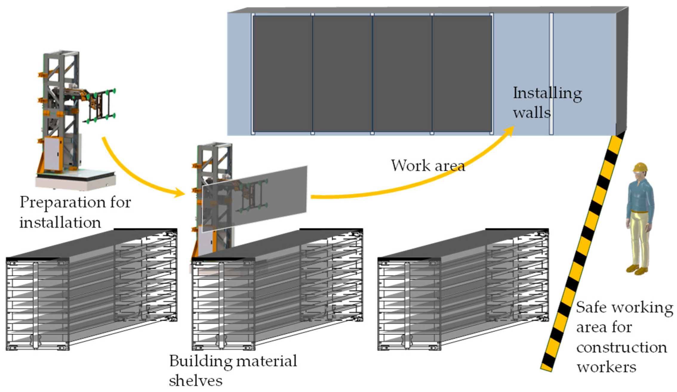
The kinematic analysis based on the MD-H method lays the basic theoretical foundations for robot kinematics. On this basis, for the specific needs of the building slabstone-installing robot, the robot must strictly follow the start and end of the path when performing the job to ensure the absolute accuracy of the installation position. In addition, the specific steps of the installation process are detailed in Figure 2, further emphasizing the importance of path accuracy. Based on this requirement, a quintic polynomial interpolation trajectory is selected to study the robot’s performance in trajectory planning. The quintic polynomial interpolation shows good smoothness and flexibility and can effectively meet the high precision requirements of the robot in the path tracking process [17]. The kinematic constraints of the building slabstone-installing robot are shown in Table 2.
For the building slabstone-installing robot, the joint variables are known. At the starting and ending points of the installation movement, the velocities and accelerations of the robot’s joints are specified to be zero [18]. If we consider the interval of the robot’s trajectory within a certain period of operation, then at the starting and ending points, the constraint conditions for the robot’s joint variables, velocities, and accelerations are as follows:
q t 0 = q 0 q t f = q f q ˙ t 0 = q ˙ t f = 0 q ¨ t 0 = q ¨ t f = 0 ,
where t 0 is the start point time, t f is the end point time, q ( t 0 ) and q ( t f ) are the position constraints of the start point and the end point, q ˙ ( t 0 ) and q ˙ ( t f ) are the speed constraints of the start point and the end point, and q ¨ ( t 0 ) and q ¨ ( t f ) are the acceleration constraints of the start point and the end point. The equation of the quintic polynomial locus is expressed as follows:
q t = a 0 + a 1 ( t t 0 ) + a 2 ( t t 0 ) 2 + a 3 ( t t 0 ) 3 + a 4 ( t t 0 ) 4 + a 5 ( t t 0 ) 5 ,
where a 0 , a 1 , a 2 , a 3 , a 4 , and a 5 are the coefficients of the fifth-degree polynomial, which can be obtained according to the constraint conditions, and the velocity and acceleration of the robot can be obtained via derivation of these values.
The building slabstone-installing robot is a serial robotic arm with seven joints. The dynamic moment of inertia parameters for this robot are listed in Table 3. Using Lagrange’s dynamics equation, the generalized torque required to drive the arm at the robot’s joint labeled i is obtained as follows:
τ i ( t ) = j = 1 n D i j q ¨ j + j = 1 n k = 1 n D i j k q ˙ j q ˙ k + D i ,
D i j = p = max i , j n t r ( T 0 , p q j J P ( T 0 , p q i ) T ) ,
D i j k = p = max i , j , k n t r ( 2 T 0 , p q j q k J P ( T 0 , p q j q j ) T ) ,
D i = p = i n m p g ( T 0 , p q i r ¯ p ) ,
where D i j represents the inertia term of the robot, D i j k represents the centrifugal force and Coriolis force term, D i represents the gravity term, T represents the matrix transposition, and τ i , q i , q ˙ i , and q ¨ i are the generalized force, moment, displacement, and velocity of the ith joint (where i is replaced by j or k to indicate the jth or kth joint), respectively, g denotes the gravitational matrix, and r ¯ p represents the centroid position of link p.
J i = 1 2 I i x x + I i y y + I i z z I i x y I i x y 1 2 I i x x I i y y + I i z z I i x z I i y z m i x ¯ i m i y ¯ i I i x z m i x ¯ i I i y z m i y ¯ i 1 2 I i x x + I i y y I i z z m i z ¯ i m i z ¯ i m i ,
where J i is the inertia matrix of the ith joint, m i is the mass of the link i, x ¯ i , y ¯ i , and z ¯ i are the position vectors of the center of mass of the link i, I i x y , I i y z , and I i x z are the inertia products of the link i, I i x x , I i y y , and I i z z are the mass inertia moments of the link i, and the dynamic moments of inertia parameters of the building slabstone-installing robot are shown in Table 3.

3. Robot Energy Consumption Optimization Strategy

3.1. Multi-Objective Optimization Algorithm

In construction and installation operations, robots frequently encounter the need to bear high loads when handling installation tasks for building facades, such as panels and glass curtain walls. Their performance is significantly influenced by factors such as speed and acceleration. Drastic changes in acceleration generate significant inertial forces, leading to vibrations and instability, particularly in heavy-duty environments where robots operate. The question of how to ensure time efficiency in task execution while minimizing energy consumption has become a crucial issue [19].
To address the aforementioned issues, this paper proposes a trajectory planning method that incorporates energy consumption mapping and multi-objective optimization. By balancing the energy consumption and time objectives during task execution by robots, it ensures efficient and stable operations. In a seven-degree-of-freedom robot, there are significant differences in torque requirements among different joints, so precise modeling is required to optimize energy consumption and task time [20,21,22,23].
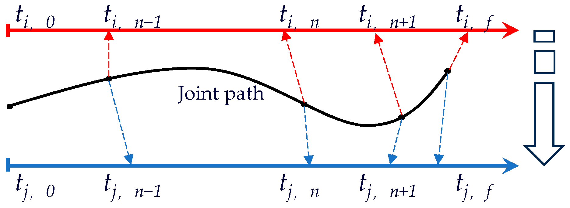
Figure 3 is a schematic diagram of robot trajectory optimization. The task is to optimize the pre-set joint path points and corresponding time parameters to ensure that the robot can achieve the best motion effect and efficiency when performing actions. This optimization strategy not only considers the accuracy of the motion but also takes into account the various challenges that may occur in the dynamic environment, so as to achieve optimal robot motion control.
To achieve optimal energy consumption and efficiency in building installation, the optimization objectives are defined as follows:
S 1 = T = i = 1 m t i = i = 1 m t i t i 1 S 2 = E = n = 1 7 t 0 t f τ i t × q ˙ i t d t ,
where T represents the total time of a working cycle of the robot. The two optimization objectives are motion time and trajectory energy consumption, which are used to evaluate the robot’s task execution efficiency and energy consumption level.
In this study, the initial population consists of a combination of legitimate joint angles randomly generated under the kinematic constraints of the robot’s joints, ensuring that each individual corresponds to a fixed path start, end, and intermediate path point. Specifically, the value of the joint angle is determined according to the inherent parameter limits of the robot in order to maintain the feasibility and variety of motion. At the same time, taking the minimum movement time and energy consumption of the path as the optimization goal, the fitness evaluation method combined with non-dominated sorting and congestion calculation is used to promote the evolution of the algorithm to a better Pareto solution. This design not only ensures the effectiveness of the initial population but also provides a solid foundation for the subsequent optimization. The specific parameters are shown in Table 4.
Energy consumption mapping constraints dynamically guide the optimization process by providing information on the energy consumption distribution within the workspace, directing trajectories toward low-energy-consumption areas, and thereby enhancing optimization efficiency:
M ( x ( t ) , y ( t ) , z ( t ) ) M t h r e s h o l d ,
where M t h r e s h o l d represents the threshold value of the energy consumption mapping, which indicates that the energy consumption of the points passed by the robot’s trajectory in the workspace must be below this threshold. It is used to restrict the generation and selection of trajectory optimization results within low-energy-consumption areas. Meanwhile, x ( t ) , y ( t ) , z ( t ) represent the trajectories of the robot end effectors in the workspace. Based on the energy consumption mapping, trajectories in low-energy-consumption areas are preferentially selected as the initial population.
q i ( 0 ) arg min ( x , y , z ) w M ( x , y , z ) ,
where the initial trajectory of the population individual is expressed as q i ( 0 ) . W stands for the robot workspace.
In the NSGA-II iteration process, the fitness of dynamic adjustment trajectory of energy consumption mapping is as follows:
F t o t a l = w 1 × S 1 + w 2 × S 2 + w 3 × M ( x , y , z ) ,
where w 1 , w 2 , w 3 represent weight coefficients that determine the priority of energy consumption, time, and energy consumption mapping. M ( x , y , z ) represents the energy consumption mapping value of the current point on the trajectory.
In each iteration, the energy consumption mapping dynamically updates the distribution of trajectory points
M k + 1 ( x , y , z ) = α × M k ( x , y , z ) + β × S 2 ,
where M k + 1 ( x , y , z ) is the kth generation energy consumption mapping value and α   β are dynamic feedback weight coefficients. The principle of parameter setting in this paper was based on normalizing the weight distribution according to the importance of the objective function. To evaluate the impact of different targets, we highlight the priority of main targets, quantify their importance, and allocate appropriate weights reasonably. Related parameters are shown in Table 5.
The normalized weighted objective function harmonizes the scales of diverse objectives through normalization and then aggregates them using weights, making it suitable for multi-objective optimization problems.
F ( x ) = j = 1 m ω j × f j x f j min f j max f j min ,
where m denotes the number of objective functions in the optimization problem, specifically the number of independent objectives that require simultaneous optimization, while f j max , f j min are the normalized upper and lower bounds. The upper and lower bounds of normalization are usually determined by the historical best and worst values of the objective function, or by a preset range to ensure that the optimization results are reasonable.
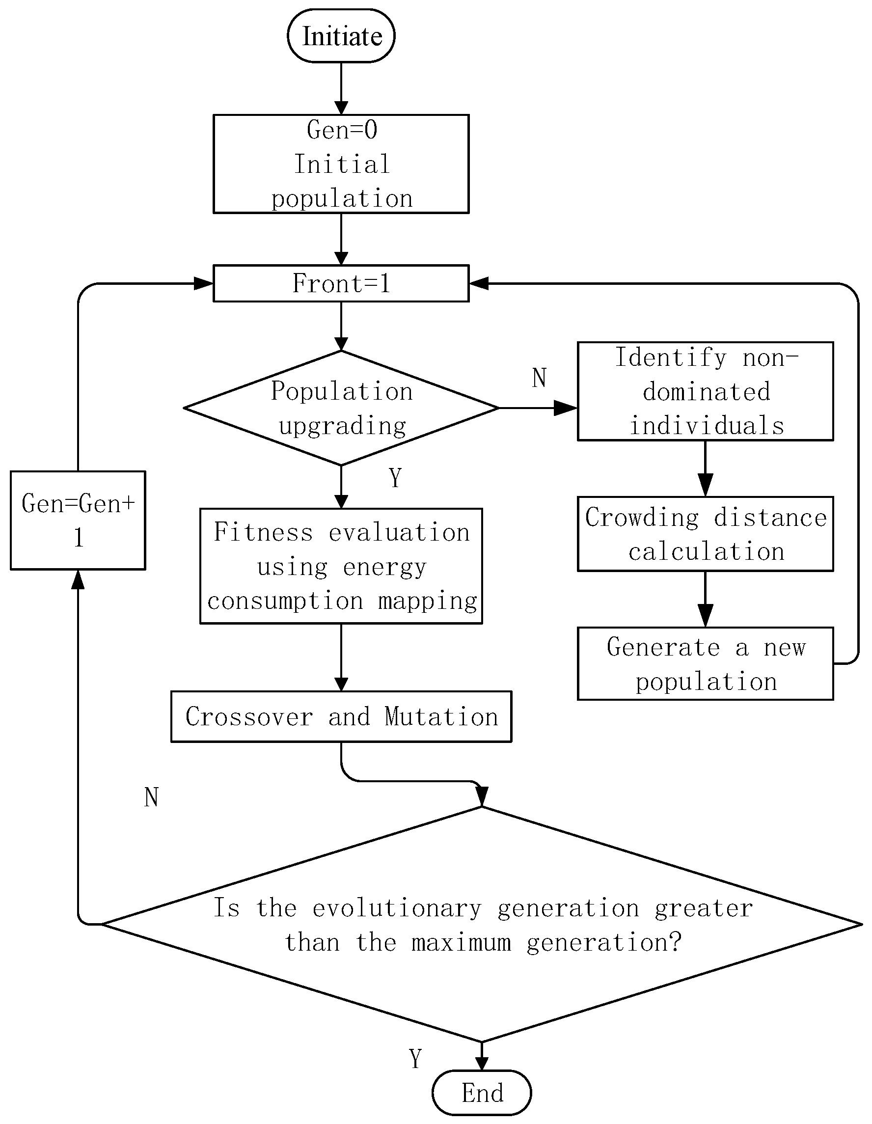
Figure 4 shows the NSGA-II optimization flow diagram with integrated energy consumption mapping.
The NSGA-II trajectory optimization algorithm combined with energy mapping first initializes a set of trajectory paths and sets energy consumption limits for joint nodes on the paths. In the fitness evaluation stage, the motion time and energy consumption of each trajectory are calculated, and the energy consumption is constrained by energy consumption mapping. Next, the algorithm performs non-dominant sorting and congestion calculation to identify high-quality solutions, selects parents through the tournament selection mechanism, and performs crossover and mutation to generate new paths. After merging the current population with the newly generated path, non-dominated sorting is performed again to maintain diversity. The process iterates until a set of termination conditions are met and finally returns a Pareto-optimal solution that provides the best tradeoff path between time and energy consumption.

3.2. Dynamic Optimization Result

In practice, in order to simplify continuous time integration, discretization is commonly employed. If the time step is Δt, the total energy consumption can be formulated in a discrete manner:
E = i = 1 n k = 1 N τ i t k × q ˙ t k × Δ t ,
where t k = t 0 + k Δ t , k = 1 , 2 , , N , Δ t = t f t 0 N is the discretization time.
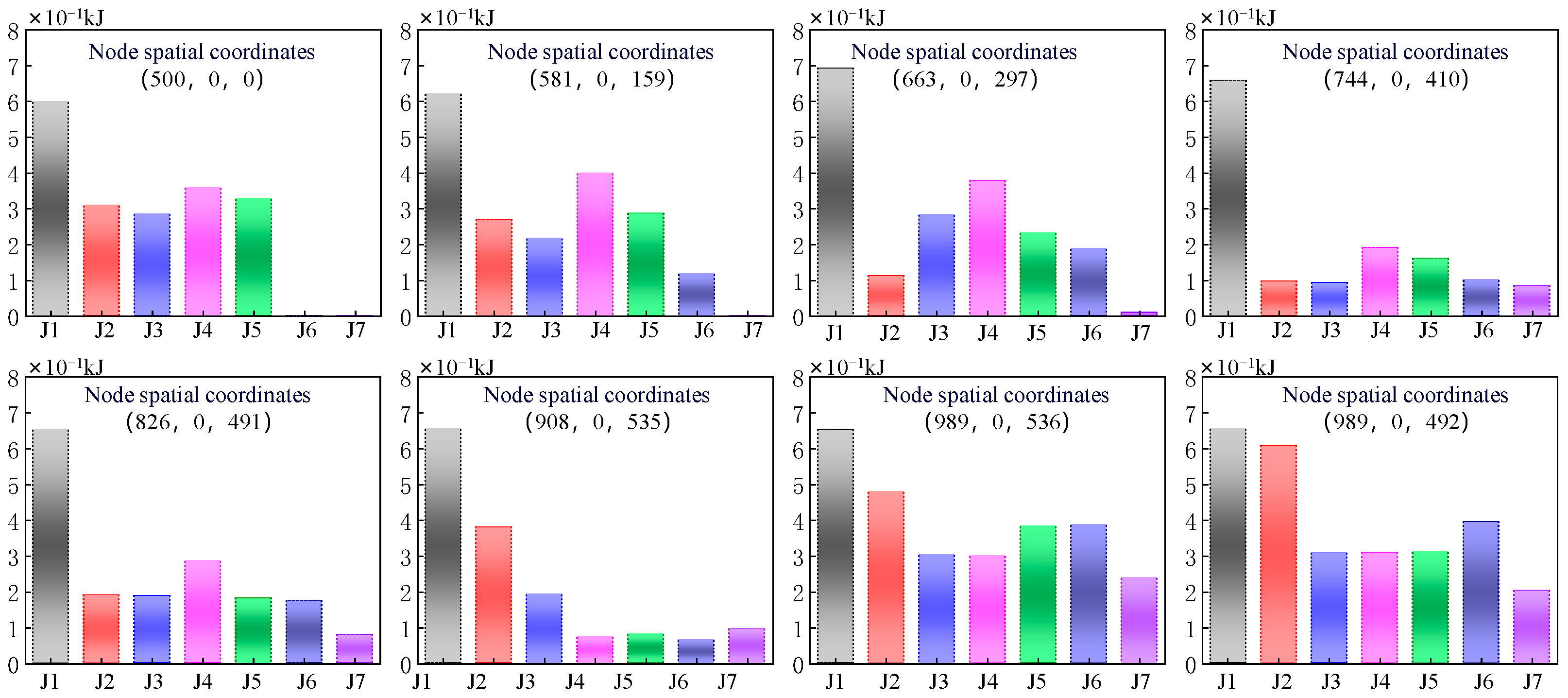
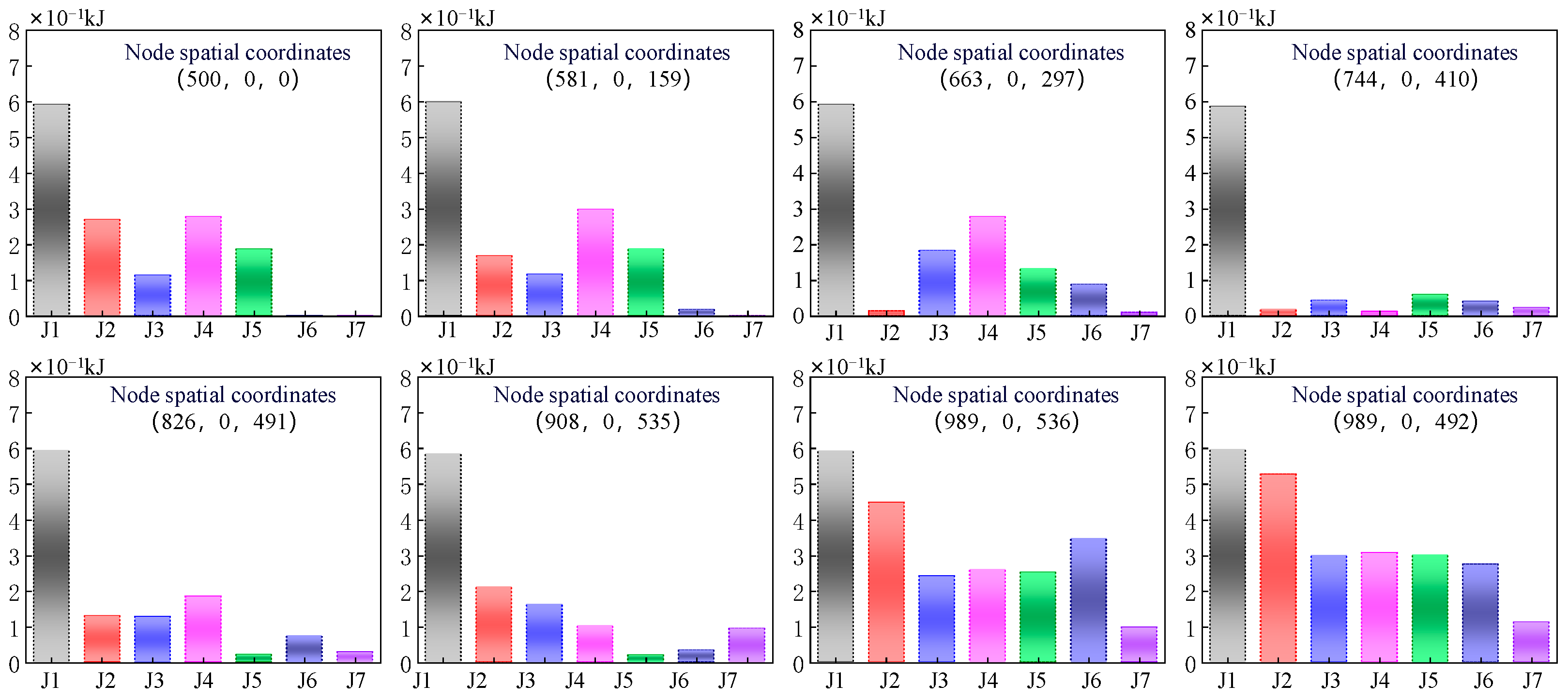
Through simulation analysis, the energy consumption characteristics of each joint under varying operating conditions are determined. By examining these data, energy consumption thresholds can be established to provide dynamic feedback and guidance for distributing trajectory points towards low-energy regions, thereby substantially enhancing optimization efficiency and the quality of the solution set. Figure 5 shows the energy consumption thresholds for each point in the trajectory space, which can effectively help researchers to analyze and evaluate the impact of different trajectory designs on energy use efficiency. It is evident that joint 1 exhibits minimal fluctuation in energy consumption, attributed to its proximity to the base and the largest load it bears. Conversely, the energy consumption of the other joints offers greater scope for optimization.
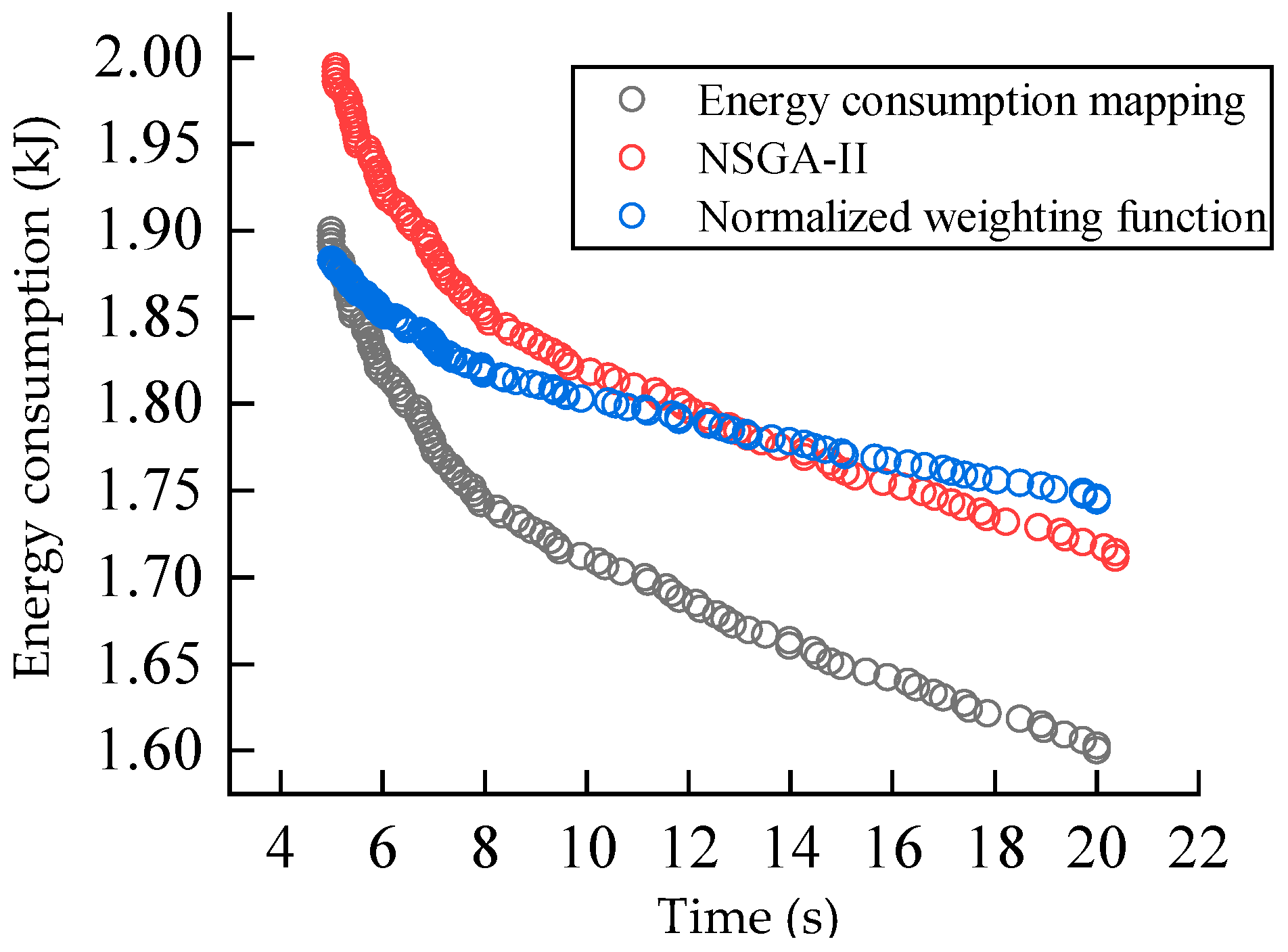
In the research on multi-objective genetic algorithms for robot trajectory optimization, three different strategies are compared: the standard NSGA-II, the NSGA-II with weighted normalization function, and the NSGA-II with integrated energy mapping technology. The standard NSGA-II emphasizes the efficient selection of solution sets in the process of multi-objective optimization, but its performance in energy consumption management is limited. The NSGA-II with a weighted normalization function is designed to balance the weights of various objects. The Pareto front diagram optimized using these three different methods is shown in Figure 6.
Relatively speaking, the NSGA-II with integrated energy consumption mapping achieves a better balance between energy consumption management and multi-objective optimization. By mapping the energy consumption distribution of the workspace in detail, this algorithm provides rich prior knowledge for optimization, so as to guide the search process more effectively. The Pareto frontier diagram shows the obvious advantages of the NSGA-II method with integrated energy mapping. In terms of avoiding high energy consumption and reducing movement time, this method can provide a set of more high-quality and evenly distributed solutions. Compared with the other two strategies, this method shows a more ideal compromise solution between time and energy consumption and significantly improves the overall performance of robot trajectory optimization. Through these comparisons, this study proves the feasibility and advantages of the NSGA-II with integrated energy mapping in practical applications.
Figure 7 illustrates the energy mapping results for each joint at the path points following optimization. It is evident from the figure that the energy consumption of each joint has undergone refinement and optimization, resulting in varying degrees of reduction. This optimization demonstrates that, through precise adjustments and algorithmic improvements, the total energy consumption of the robot during task execution is effectively minimized. Notably, the joints that previously exhibited high energy consumption during movement have significantly enhanced their energy efficiency as a result of this optimization strategy.
Figure 8 shows the comparison of robot positions before and after optimization. Upon comprehensive analysis of three distinct optimization methods, it is evident from the result graph that the method based on the NSGA-II combined with energy consumption mapping significantly outperformed both the standard NSGA-II and the weighted normalized function NSGA-II in terms of displacement time. At the first joint of the robot, all three methods exhibited similar optimization effects, as the dynamic characteristics and energy consumption patterns of this joint were relatively straightforward and had minimal impact on the overall energy consumption. However, in terms of the optimization effects observed on the remaining joints, the method incorporating energy consumption mapping demonstrated more pronounced advantages. This approach facilitated more precise control over the energy consumption of each joint and optimized its motion trajectory, thereby reducing unnecessary energy consumption and enhancing overall motion efficiency.
Figure 9 clearly shows the torques and time graphs of three different optimization strategies using the standard NSGA-II, the energy consumption mapping method, and the normalized weighting function. Among the three methods, due to the large number of robot-driven joints and uneven mass distribution, the optimization effects of different joints exhibited obvious differences. In particular, the first two joints of the robot, which are located near the base, were mainly responsible for the movement and rotation of the robot arm. These joints not only bore the weight of the entire robot arm but were also directly affected by the external load during operation, so the optimization of their torque was particularly critical. In this case, the standard NSGA-II performed the most poorly, as it lacked comprehensive consideration of specific robot dynamics and energy efficiency. In contrast, energy mapping methods and normalized weighted function optimization could better adapt to the specific needs of each joint through finer control and adjustment, especially in cases of heavy loads and high dynamic requirements, which significantly reduced energy consumption and optimized torque output. By integrating actual energy consumption data into the optimization process, the energy consumption and torque of each joint could be effectively managed and optimized. Meanwhile, the normalized weighting function could adjust the weight ratio of each target to make the optimization more suitable for the performance requirements in actual operation. As a result, the joints optimized by the energy consumption mapping and normalized weighting function exhibited smoother torque curves that met the design requirements on the torque–time diagram, while the standard NSGA-II underperformed due to the lack of targeted adjustments. The comparison results emphasize the importance of adopting an optimization strategy that comprehensively considers the robot structure and energy consumption characteristics in robot trajectory optimization.
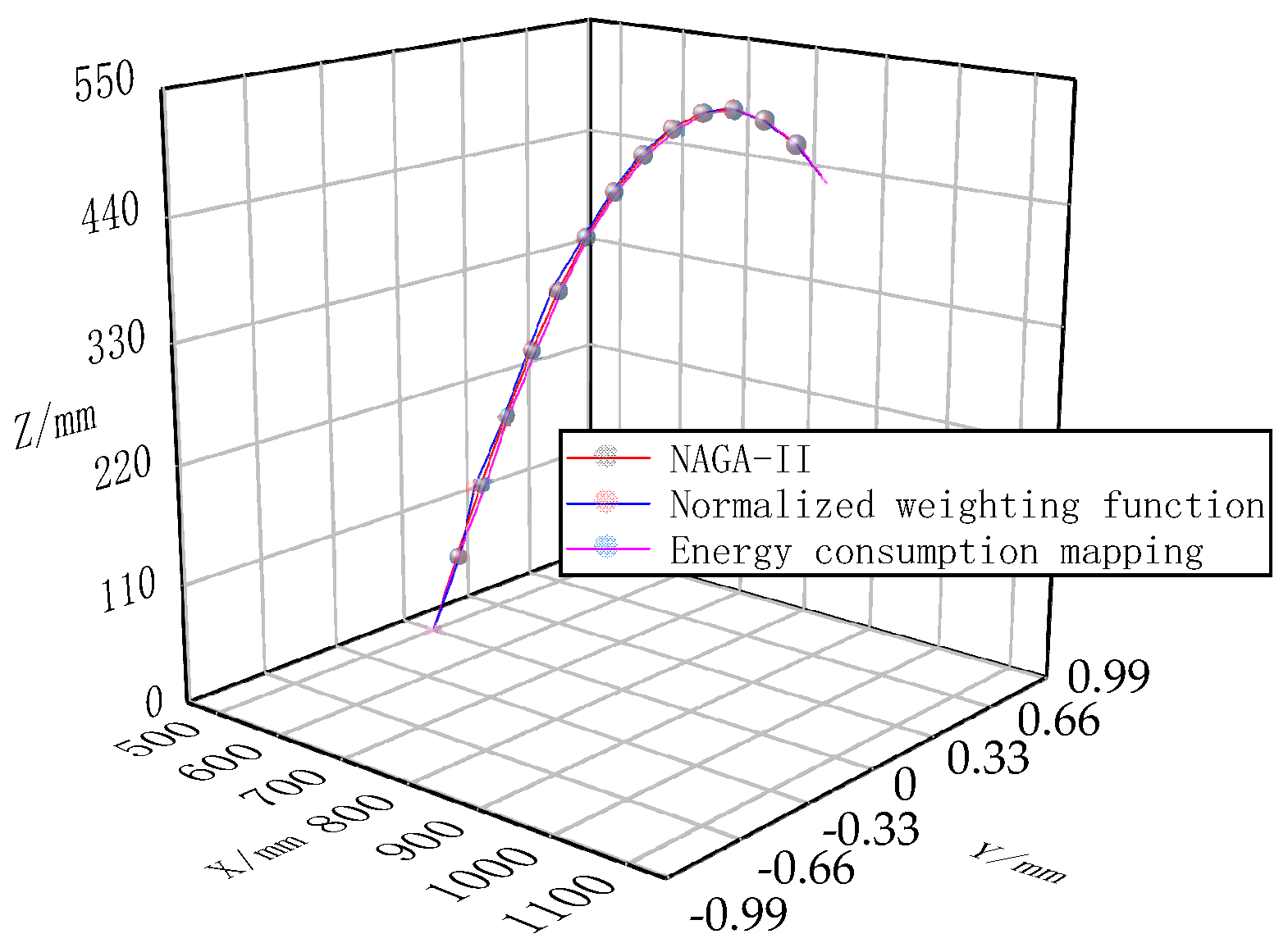
Figure 10 shows the comparison results of trajectories optimized using the energy consumption mapping method, the standard NSGA-II, and the normalized weighted function. Although the changes exhibited by the three optimization methods in the spatial trajectory path are very weak, they demonstrate the good consistency of the algorithm under different optimization strategies, ensuring the stability and reliability of the path. This consistency is particularly important for the precise control of the robot.

4. Experimental Conditions and Results

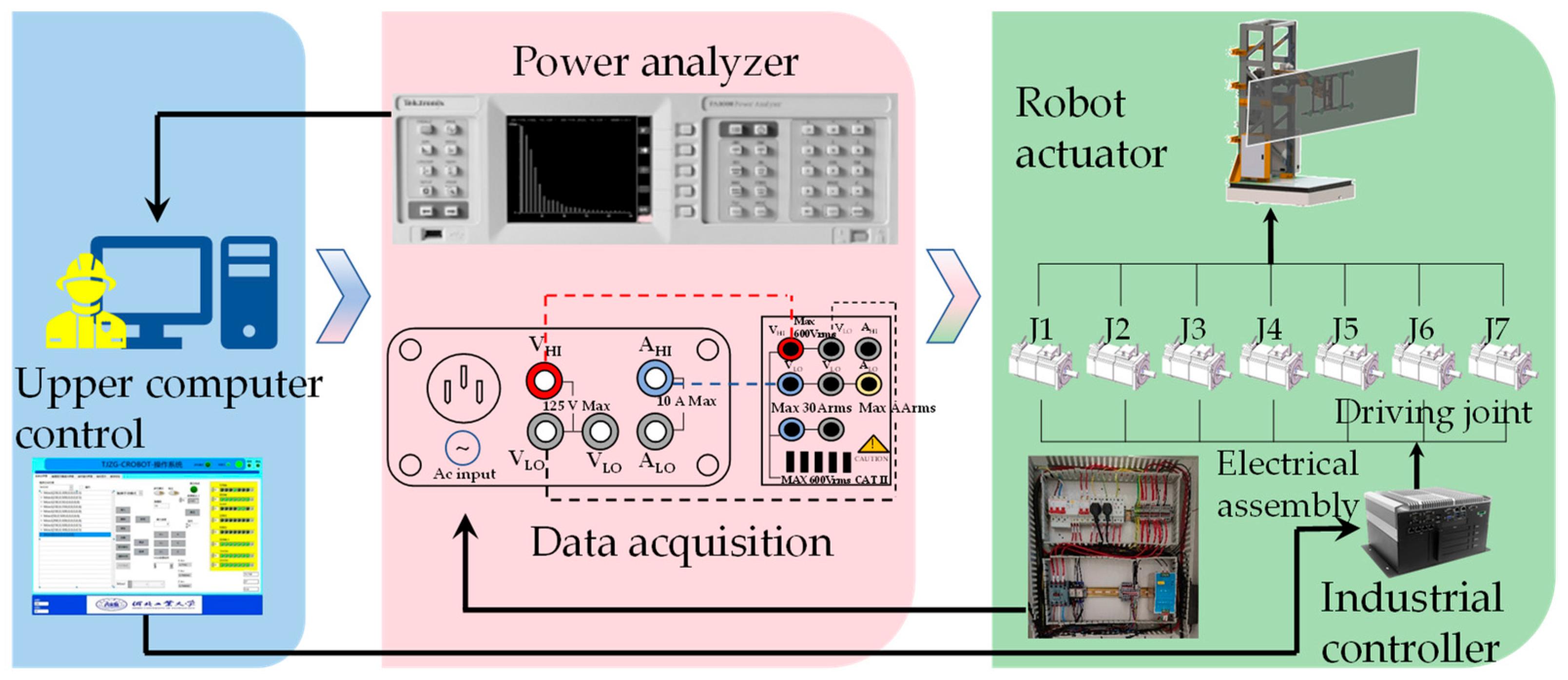
In this research, according to the common working conditions of the building slabstone-installing robot, the detailed work and data collection of its installation process were carried out. In this process, the motion cycle instructions sent by the host computer to the robot are derived based on optimization strategies to improve operational efficiency and accuracy to drive the robot to perform a series of preset actions, thereby generating comprehensive motion and energy consumption data. At the same time, in order to adapt to the changing environment, real-time data acquisition technology is adopted, so that the robot can carry out adaptive mapping under dynamic conditions. At the completion of each action, all collected data are saved to a compatible flash drive via the USB interface of the PA3000 power analyzer (Tektronix, Oregon, U.S.)to ensure data integrity and accuracy. At the end of the whole data collection process, the real energy consumption and motion performance data of the robot in large and medium-sized plate installation tasks were successfully obtained. Figure 11 shows the block diagram and key components of the robot installation experimental system.
Using the building slabstone-installing robot as the experimental subject, its simulated actual working environment is shown in Figure 12, including the installation path, heavy-load conditions, and key operational areas.
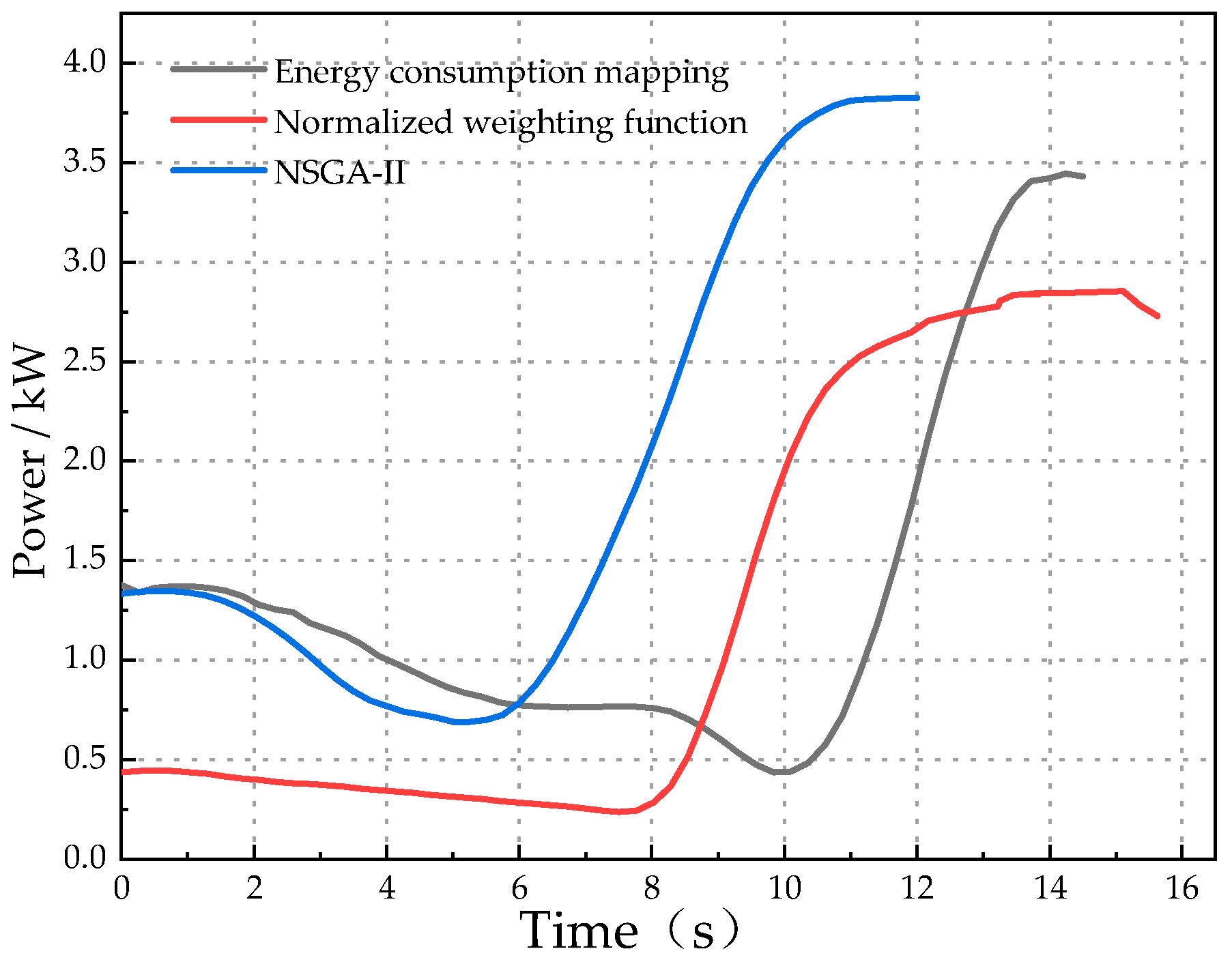
By comprehensively collecting and analyzing the data of the seven joints of the robot, the power curve was successfully generated, as shown in Figure 13. In a detailed analysis of the power curve for loads of 200 kg and below, the results show that the difference in efficiency is relatively small in the first 8 s before and after optimization, mainly due to the significant influence of load weight and inertial forces. Although the optimization failed to significantly improve work efficiency at this stage, eight seconds after entering the handling phase, the optimized robot showed a significant performance improvement, fully demonstrating the potential of the optimization algorithm under certain operating conditions.
Further experimental data show that after integral analysis of the power curve, the energy consumption of the ordinary NSGA-II method, normalized weighted function method, and NSGA-II method combined with energy consumption mapping are 22,176.5 joules, 21,086.2 joules and 18,878 joules, respectively. These results clearly show that the optimized scheme reduces energy consumption by 14.87% compared to the traditional NSGA-II method, and the robot’s energy consumption is reduced by 10.47% compared to the normalized weighted function method. The experimental results fully verify the effectiveness and superior energy-saving ability of the trajectory optimization strategy proposed in this study in practical applications and lay a solid foundation for future robot trajectory optimization research.

5. Conclusions

In this research, a multi-objective trajectory optimization method combining energy mapping and the NSGA-II is proposed to minimize the energy consumption and time of a robot’s trajectory at the same time. By constructing the energy consumption model and implementing the energy mapping of the workspace, prior knowledge is provided to guide the optimization process. The NSGA-II is used to generate an optimal Pareto solution set with uniform distribution and high quality, which adopts non-dominated sorting and a dynamic feedback mechanism.
The experimental results show that compared with the traditional NSGA-II method, the proposed method can effectively reduce the energy consumption by 14.87%, and the robot can achieve 10.47% energy savings compared with the weighted function method. These results not only validate the validity of this method but also highlight its importance in engineering applications. Major contributions include the following:
(1).
The introduction of energy consumption mapping: The energy consumption distribution model of the workspace is constructed to provide guidance for the identification of low-energy-consumption areas in the optimization process, which is of great significance for improving the energy efficiency of the robot.
(2).
Multi-objective optimization combined with the NSGA-II: Through the NSGA-II, we aim to achieve a balance between minimizing energy consumption and time and generate a Pareto-optimal solution set. This provides an effective solution for multi-objective optimization, especially for applications in complex task environments.
(3).
Dynamic feedback mechanism: In the optimization process, relying on energy consumption mapping, the population distribution is adjusted in real time, thus improving the convergence of the algorithm and enhancing the uniformity of the solution set.
In summary, this method is particularly suitable for the trajectory optimization of industrial robots and autonomous robots in complex task environments and provides a new way to deal with the problem of high energy consumption of robots. In the future, we will continue to explore the construction method of real-time energy consumption mapping to achieve dynamic monitoring and optimization of energy efficiency of robot systems. The application of this method in multi-robot collaboration will be further studied, and different collaboration scenarios will be specifically investigated, with special attention paid to the coordination of task assignment and path planning, so as to effectively improve the overall performance and scalability of the system. In addition, it is planned to integrate multiple optimization algorithms, including hybrid models, to enhance the robustness and adaptability of the system in different application scenarios. By comparing it with existing methods, the effectiveness and practical application performance of the proposed method are expected to be verified more comprehensively. These efforts will improve the energy efficiency and flexibility of robotic systems, advancing their potential applications in complex and dynamic environments.

Author Contributions

D.Y. and M.H. conceived and designed this study and translated the article. X.W. performed statistical analyses and wrote the article. All authors have read and agreed to the published version of the manuscript.

Funding

This research was supported by the Scientific research projects of colleges and universities in Hebei Province (NO. QN2024063) and The Best Supported Postdoctoral Scientific Research Projects in Hebei Province (NO. B2023005005).

Data Availability Statement

The data for the paper can be requested from the corresponding author.

Conflicts of Interest

The authors declare no conflicts of interest.

References

  1. Soori, M.; Arezoo, B.; Dastres, R. Optimization of energy consumption in industrial robots, a review. Cogn. Robot. 2023, 3, 142–157. [Google Scholar] [CrossRef]
  2. Bugmann, G.; Siegel, M.; Burcin, R. A role for robotics in sustainable development? In Proceedings of the IEEE Africon ’11, Victoria Falls, Zambia, 13–15 September 2011; pp. 1–4. [Google Scholar]
  3. Bouaziz, N.E.I.; Mechali, O.; Besseghieur, K.L.; Achour, N. Trajectory Planning for Autonomous Formation of Wheeled Mobile Robots via Modified Artificial Potential Field and Improved PSO Algorithm. Unmanned Syst. 2024, 12, 1085–1104. [Google Scholar] [CrossRef]
  4. Pellicciari, M.; Berselli, G.; Leali, F.; Vergnano, A. A method for reducing the energy consumption of pick-and-place industrial robots. Mechatronics 2013, 23, 326–334. [Google Scholar] [CrossRef]
  5. Mohammed, A.; Schmidt, B.; Wang, L.; Gao, L. Minimizing energy consumption for robot arm movement. Procedia CIRP 2014, 25, 400–405. [Google Scholar] [CrossRef]
  6. Van Oosterwyck, N.; Vanbecelaere, F.; Knaepkens, F.; Monte, M.; Stockman, K.; Cuyt, A.; Derammelaere, S. Energy optimal point-to-point motion profile optimization. Mech. Based Des. Struct. Mach. 2024, 52, 239–256. [Google Scholar] [CrossRef]
  7. Nonoyama, K.; Liu, Z.; Fujiwara, T.; Alam, M.M.; Nishi, T. Energy-efficient robot configuration and motion planning using genetic algorithm and particle swarm optimization. Energies 2022, 15, 2074. [Google Scholar] [CrossRef]
  8. He, Y.; Mei, J.; Fang, Z.; Zhao, Y. Minimum Energy Trajectory Optimization for Driving Systems of Palletizing Robot Joints. Math. Probl. Eng. 2018, 2018, 7247093. [Google Scholar] [CrossRef]
  9. Qie, X.; Kang, C.; Zong, G.; Chen, S. Trajectory Planning and Simulation Study of Redundant Robotic Arm for Upper Limb Rehabilitation Based on Back Propagation Neural Network and Genetic Algorithm. Sensors 2022, 22, 4071. [Google Scholar] [CrossRef]
  10. Benghezal, A.; Nemra, A.; Bouaziz, N.E.I.; Tadjine, M. New robust backstepping attitude control approach applied to quanser 3 DOF hover quadrotor in the case of actuators faults. Unmanned Syst. 2024, 12, 3–17. [Google Scholar] [CrossRef]
  11. Cui, Y.; Geng, Z.; Zhu, Q.; Han, Y. Multi-objective optimization methods and application in energy saving. Energy 2017, 125, 681–704. [Google Scholar] [CrossRef]
  12. Serralheiro, W.; Maruyama, N.; Saggin, F. Self-Tuning Time-Energy Optimization for the Trajectory Planning of a Wheeled Mobile Robot. J. Intell. Robot. Syst. 2019, 95, 987–997. [Google Scholar] [CrossRef]
  13. Ma, H.P.; Zhang, Y.J.; Sun, S.Y.; Liu, T.; Shan, Y. A comprehensive survey on NSGA-II for multi-objective optimization and applications. Artif. Intell. Rev. 2023, 56, 15217–15270. [Google Scholar] [CrossRef]
  14. Holzmann, P.; Pfefferkorn, M.; Peters, J.; Findeisen, R. Learning Energy-Efficient Trajectory Planning for Robotic Manipulators Using Bayesian Optimization. In Proceedings of the 2024 European Control Conference, Stockholm, Sweden, 25–28 June 2024; pp. 1374–1379. [Google Scholar]
  15. Paryanto; Brossog, M.; Bornschlegl, M.; Franke, J. Reducing the energy consumption of industrial robots in manufacturing systems. Int. J. Adv. Manuf. Technol. 2015, 78, 1315–1328. [Google Scholar] [CrossRef]
  16. Quann, M.; Ojeda, L.; Smith, W.; Rizzo, D.; Castanier, M.; Barton, K. Off-road ground robot path energy cost prediction through probabilistic spatial map. J. Field Robot. 2020, 37, 421–439. [Google Scholar] [CrossRef]
  17. Tipary, B.; Kovács, A.; Erdős, F.G. Planning and optimization of robotic pick-and-place operations in highly constrained industrial environments. Assem. Autom. 2021, 41, 626–639. [Google Scholar] [CrossRef]
  18. Bilal, H.; Yin, B.; Kumar, A.; Ali, M.; Zhang, J.; Yao, J. Jerk-bounded trajectory planning for rotary flexible joint manipulator: An experimental approach. Soft Comput. 2023, 27, 4029–4039. [Google Scholar] [CrossRef]
  19. Bonello, A.; Refalo, P.; Francalanza, E. The Impacts of Industrial Safety on Environmental Sustainability in Human-Robot-Collaboration within Industry 5.0. Procedia CIRP 2024, 122, 282–287. [Google Scholar] [CrossRef]
  20. Kong, M.X.; Chen, L.; Du, Z.; Sun, L. Multi-objective Optimization on Dynamic Performance for a Planar Parallel Mechanism with NSGA-II Algorithm. Robot 2010, 32, 271–277. [Google Scholar] [CrossRef]
  21. Llopis-Albert, C.; Rubio, F.; Valero, F. Improving productivity using a multi-objective optimization of robotic trajectory planning. J. Bus. Res. 2015, 68, 1429–1431. [Google Scholar] [CrossRef]
  22. Zhang, P.; Yao, Z.; Du, Z. Global performance index system for kinematic optimization of robotic mechanism. J. Mech. Des. 2014, 136, 031001. [Google Scholar] [CrossRef]
  23. Yang, C.; Ye, W.; Li, Q. Review of the performance optimization of parallel manipulators. Mech. Mach. Theory 2022, 170, 104725. [Google Scholar] [CrossRef]
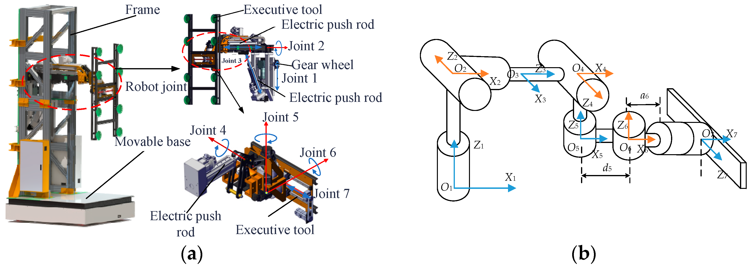
Figure 1. Robot model for plate installation: (a) overall design drawing; (b) structural sketch.
Robotics 14 00138 g001
Figure 2. Schematic diagram of the building slabstone-installing robot.
Robotics 14 00138 g002
Figure 3. Schematic diagram of trajectory optimization.
Robotics 14 00138 g003
Figure 4. Flowchart of NSGA-II optimization with integrated energy consumption mapping.
Robotics 14 00138 g004
Figure 5. Trajectory energy consumption mapping threshold of a key node.
Robotics 14 00138 g005
Figure 6. Pareto-optimal solution distribution front.
Robotics 14 00138 g006
Figure 7. Energy consumption mapping after trajectory space optimization.
Robotics 14 00138 g007
Figure 8. Displacement optimization results of different methods: (a) Standard NSGA-II displacement optimization results; (b) combined with the displacement optimization results of energy consumption mapping; (c) normalized weighted function displacement optimization results.
Robotics 14 00138 g008
Figure 9. Torque after optimization with different optimization methods: (a) standard NSGA-II optimized torque–time diagram; (b) torque–time diagram optimized with energy consumption mapping; (c) torque–time graph optimized with the normalized weighting function.
Robotics 14 00138 g009
Figure 10. Trajectories optimized by means of different optimization methods.
Robotics 14 00138 g010
Figure 11. Block diagram of the simulated panel installation experimental system.
Robotics 14 00138 g011
Figure 12. Robot handling operation experiment of plate installation.
Robotics 14 00138 g012
Figure 13. Total power of the robot during its motion cycle.
Robotics 14 00138 g013
Table 1. Modified D-H parameter table.
Joint iJoint 1Joint 2Joint 3Joint 4Joint 5Joint 6Joint 7
θ i 0 π 4 , π 2 0 3 π 4 , π 4 π 2 , π 2 π 2 , π 2 0
d i [0,2]0[0,1]0−0.2340[0,0.511]
a i 000000.1580
α i 0 π 2 π 2 π 2 π 2 π 2 π 2
Table 2. Kinematic constraints of the building slabstone-installing robot’s joints.
Joint iSpeed (m/s)Acceleration (rad/s)Joint iAngular Velocity (m/s2)Angular Acceleration (rad/s2)
Joint 10.1133.54Joint 21.2981.5
Joint 30.06255.85Joint 41.2981.5
Joint 70.06253Joint 51.2981.39
Joint 61.2981.5
Table 3. Dynamic inertia table of the building slabstone-installing robot.
LinkQualityThe Centroid of the LinkMoment of Inertia (kg × mm2)
imi (kg)Pci (m) I x x I y y I z z I x y I x z I y z
161.789[0,0,2]292.555289.4893.740.0035.6150.042
289.005[0.319,0,2]503.141520.20319.360.00369.6890.014
3136[0.644,0,2]987.6911065.70289.4284.662230.98533.607
445.071[0.982,0,2]418.916473.87955.3720.311146.0690.568
529.761[1.6,0,1.7]191.376269.93578.8560.319122.4930.217
628.402[1.6,0,1.7]152.392231.97479.8080.136110.0120.189
716.032[1.9,0,1.7]84.97138.69554.170.59767.2930.668
Table 4. Design of the main parameters of the NSGA-II.
Parameters and NamesValue
Population size N200
Competition scale St2
Crossover probability Pc0.5
Mutation probability Pm0.9
Maximum generation G500
Table 5. Values of key parameters.
Argument w 1 w 2 w 3 α β
Value0.20.20.60.50.5
Disclaimer/Publisher’s Note: The statements, opinions and data contained in all publications are solely those of the individual author(s) and contributor(s) and not of MDPI and/or the editor(s). MDPI and/or the editor(s) disclaim responsibility for any injury to people or property resulting from any ideas, methods, instructions or products referred to in the content.