1. Introduction
Legged climbing robots for space applications are designed to move in uneven, steep, vertical, or even overhead environments. Similar to NASA’s LEMUR 3 [
1], Capuchin [
2], or the climbing robot by Nagaoka et al. [
3], they often rely on the existence of sufficient holding points or hold points suitable for the legs’ end-effectors to hold on to. In environments with sparse holding points, climbing becomes challenging because there may not be enough holding points within the reach of the legs. Enlarging the legs is a potential solution to this problem. However, limitations arise due to the restricted carrying capacity of the legs’ end-effectors and the high cost associated with transporting mass to space. This has led to the exploration of solutions in other types of robots.
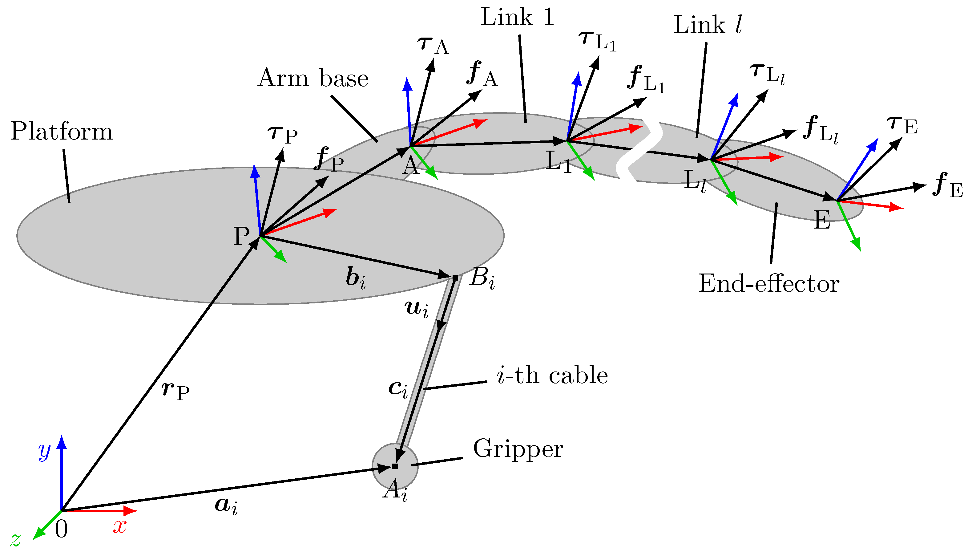
Cable-driven parallel robots use cables connected to the surroundings as prismatic joints to manipulate the robot’s pose. Compared to the rigid and prismatic joints of conventional robots, cables have a low mass and size, allowing the robot to achieve a large workspace and reach high velocity and acceleration. However, the cables have to be kept under tension to maintain the static equilibrium of the robot. Cable-driven parallel robots are classified by their number of cables
m: if
, the robot is considered incompletely restrained [
4]. In this case, not all degrees of freedom can be controlled and the set of external wrenches the robot can withstand at a given pose is limited. If
, the robot is kinematically fully constrained. However, it is still considered incompletely restrained as it has to rely on external wrenches to keep the cables under tension. If
, the robot is considered completely restrained (
) or redundantly restrained (
) [
4] and the robot can withstand a set of wrenches at a given pose limited by the minimum and maximum forces in the cables.
Cable-driven climbing robots—sometimes referred to as tethered climbing robots [
5,
6], drawing an analogy to the term tether, which is used for ropes in human rock climbing—try to incorporate the advantages of cable-driven robots into legged climbing robots by replacing the legs with cables. They employ a secondary mechanism (e.g., a robotic arm) to relocate the end-effectors. Thus, by repeatedly changing the pose of the platform and relocating the end-effectors with the secondary mechanism, climbing locomotion can be achieved. The large workspace inherent to cable-driven parallel robots allows cable-driven climbing robots to reach more holding points, improving climbing performance in an environment with sparse holding points. In addition, the high velocity and acceleration of the platform are beneficial for other tasks the climbing robot has to perform (e.g., servicing or manufacturing). These robots are well-suited for space applications. For example, they can be used as servicing robots on the outside of a space station, which only provides a few holding points in the form of handrails or docking adapters for robotic arms. They are also useful as exploration robots on rocky, steep surfaces of asteroids, which may only have few holding points with a suitable geometry for the end-effectors. Furthermore, they have the potential to provide a more lightweight, compact, and agile alternative to existing space robots.
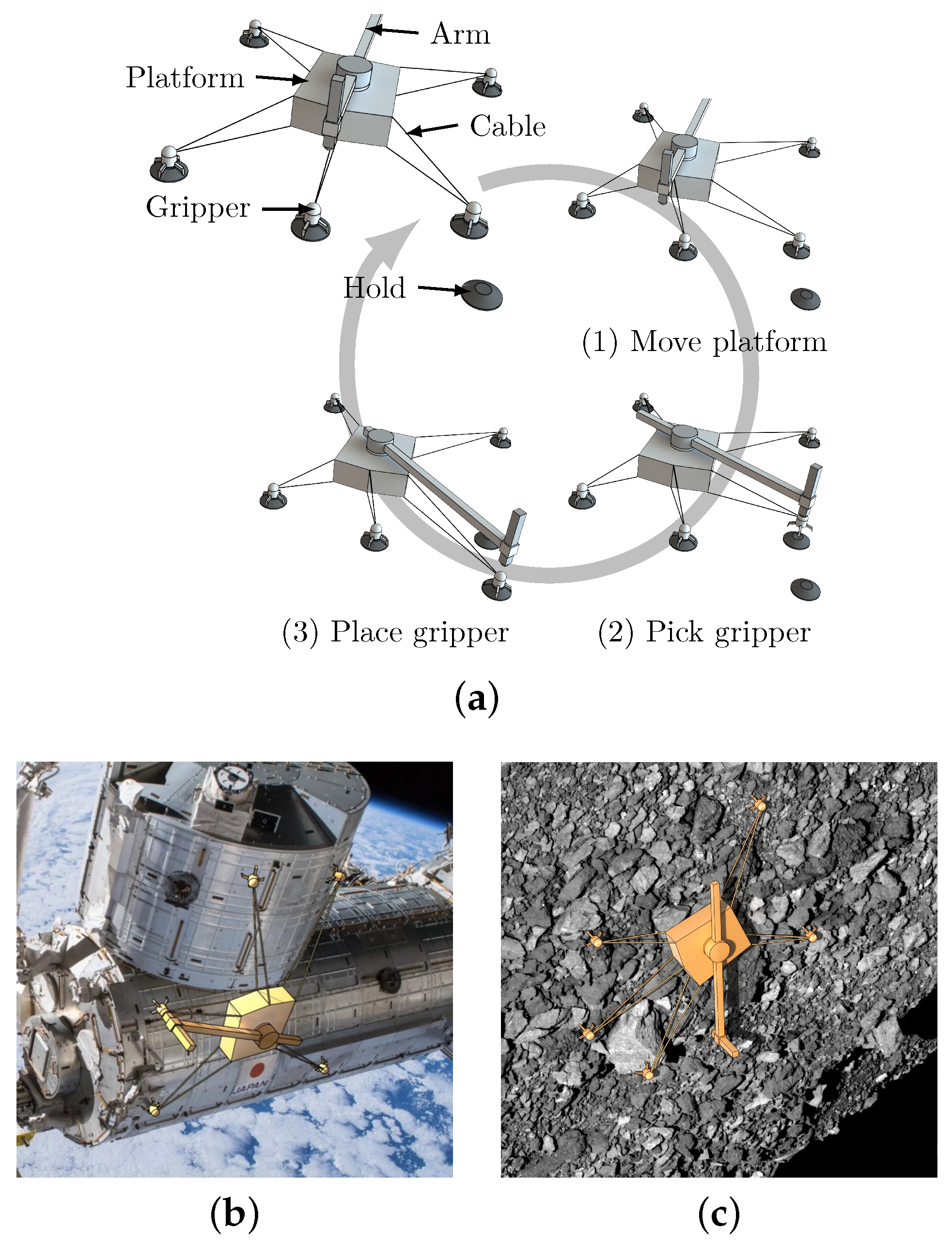
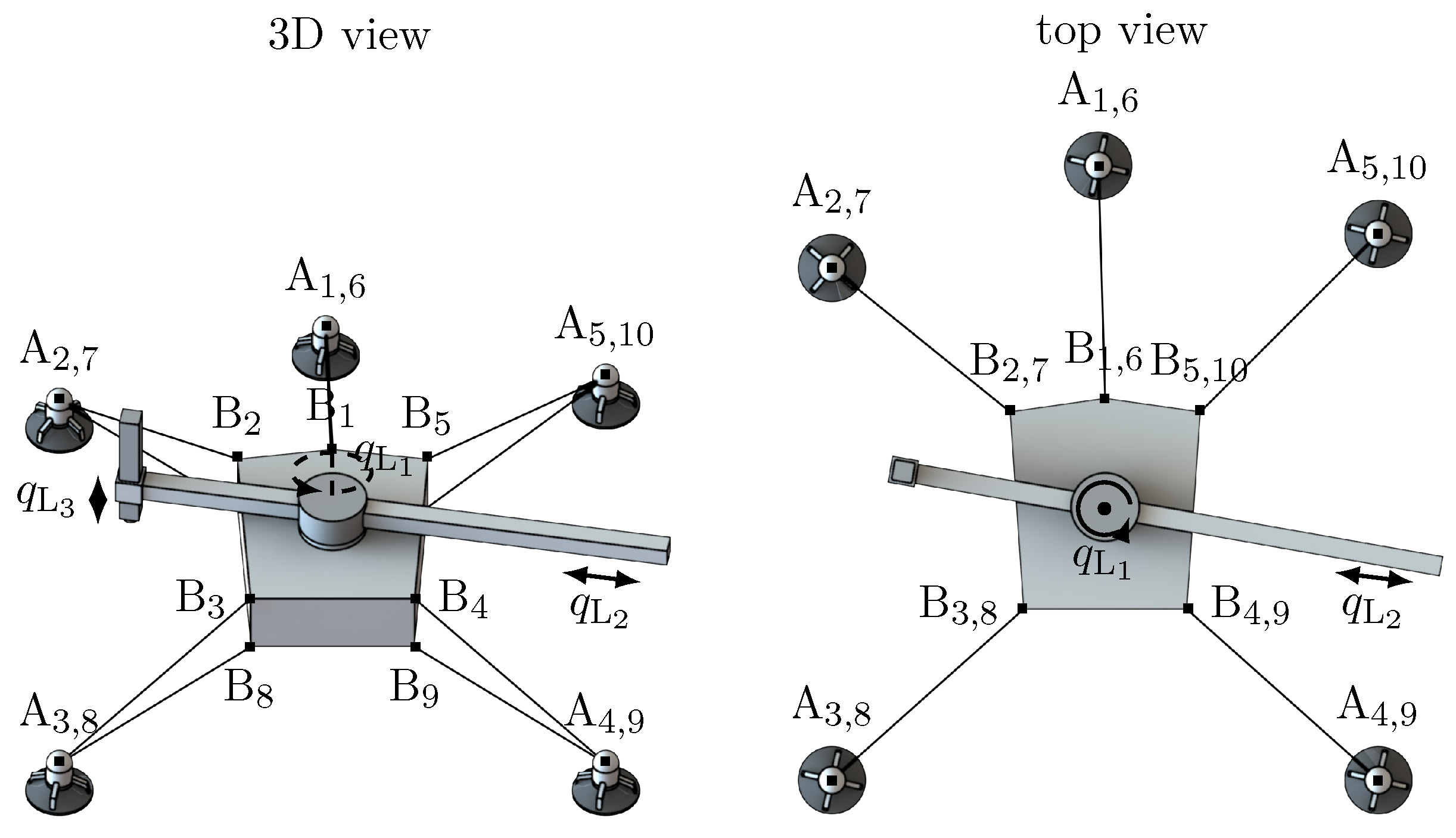
We present Tetherbot, shown in
Figure 1, a cable-driven climbing robot with ten cables connected to five end-effectors, hereinafter referred to as grippers, in a redundantly restrained configuration. The platform has a robotic arm to pick and place the grippers between different holding points. Tetherbot achieves climbing locomotion by repeatedly moving the platform and moving the grippers from one hold to the next, as illustrated in
Figure 1a. Its applications include servicing space stations and satellites (
Figure 1b) as well as exploring minor planetary bodies such as asteroids (
Figure 1c).
The main contribution of this work is the first experimental demonstration of autonomous cable-driven climbing in an environment with sparse holding points. To this end, we outline the design, kinematics, and statics of Tetherbot. Furthermore, we present a path planning algorithm to pick and place the grippers between the holding points to achieve climbing locomotion.
2. Related Works
Motion planning for legged and cable-driven climbing robots in environments with sparse holding points generally consists of two steps. First, one has to determine in which order the robot should grasp the holding points, i.e., step planning. Then, the path of the robot is computed, i.e., path planning. This approach, also referred to as the contact-before-motion framework [
9], has been successfully implemented and validated for different legged climbing robots like LEMUR [
9] and Capuchin [
2]. The opposite approach, motion-before-contact, first determines the path of the robot and then the placement of the end-effectors [
9]. Therefore, it is employed in uniform environments where the placement of the end-effectors is not a major concern.
Cable-driven climbing robots, on the other hand, represent a relatively unexplored field of climbing robots. Capua et al. [
10] introduced SpiderBot, an incompletely restrained cable-driven climbing robot for ferromagnetic ceilings. It uses a suspended four-cable configuration, with gravity acting as an additional cable. Each cable is equipped with a magnetic gripper and a dispenser unit as the secondary mechanism, which can retract the gripper and shoot it to a new location like a grappling hook. The authors discuss different motion planners based on the motion-before-contact approach [
10,
11], and experiments are conducted with a prototype [
10]. SpiderBot’s dependence on gravity, its secondary mechanism, and its motion planning approach makes it unsuited for space environments with sparse anchor points.
Oda et al. [
5] introduced Astrobot, an incompletely restrained four-cable climbing robot designed as a servicing robot for both the interior and exterior of a space station. Astrobot utilizes grippers to grab holding points on a space station, such as handrails, and employs a robotic arm for relocating the grippers. Its design and climbing locomotion are similar to that of Tetherbot as it served as the primary inspiration for our research. Astrobot’s incompletely restrained nature makes it difficult to calculate the state of its platform (position, orientation, and cable lengths) due to the coupling of statics and kinematics. To address this, the authors explore numerical algorithms to determine the platform’s state and discuss different motions along predefined paths which either fix the position, orientation, or cable lengths [
12,
13]. Elements of Astrobot’s motion, such as platform movement, have been demonstrated with a simplified prototype on the International Space Station [
13,
14]. However, a full prototype as well as a demonstration of the full locomotion principle, including motion planning, have not been presented. Astrobot’s kinematics and statics are equivalent to hybrid cable-driven robots, cable-driven robots whose platforms are equipped with a robotic arm. Both the statics and kinematics [
15,
16], as well as motion planning, have been discussed in the literature [
17].
Lastly, Schneider et al. [
18] introduced ReachBot, a legged climbing robot for a microgravity environment with sparse holding points. Each leg consists of an active ball joint, an extendable boom (acting as a prismatic joint), a passive ball joint, and a gripper. Similar to cable-driven robots, ReachBot must maintain the forces inside the booms within certain limits to prevent buckling. But, unlike cables, the booms also tolerate some compression forces. The authors discuss a contact-before-motion motion planning algorithm whose path planning combines sampling-based methods with sequential convex optimization [
19].
In summary, cable-driven climbing locomotion has been discussed in prior works including elements like kinematics, statics, and motion planning, either directly or indirectly. Simulations and simplified experiments have verified partial aspects of the locomotion principle. However, for cable-driven climbing in environments with sparse anchor points, there has been a lack of real-world, experimental validation for the locomotion principle, including motion planning. Additionally, redundantly constrained cable-driven climbing robots with robotic arms like Tetherbot remain unexplored in the literature.
Tetherbot operates in an environment with sparse holding points and utilizes a contact-before-motion approach for its motion planning. The step planning employs a stance graph where each node represents a feasible stance (the arrangement of the grippers on the holds) and each edge represents a feasible transition between two stances. The A*-algorithm is used to find a sequence of stances between the initial to the goal stance. Subsequently, a path planner determines the detailed path of the platform and arm. The step planning is discussed in detail in our previous work [
20]. In this paper, we focus on the path planning and experimental validation.
4. Path Planning
Tetherbot’s path planning algorithm first generates a feasible path and then calculates the trajectory of both the platform and arm to pick and place a gripper. As the input, the index of the gripper to pick and the index of the hold where the gripper should be placed are given. It is assumed that the geometry of the environment, as well as the position and orientation of the holding points, is known beforehand.
The pick and place motion consists of three major phases: moving the platform, picking the gripper, and placing the gripper, as shown in
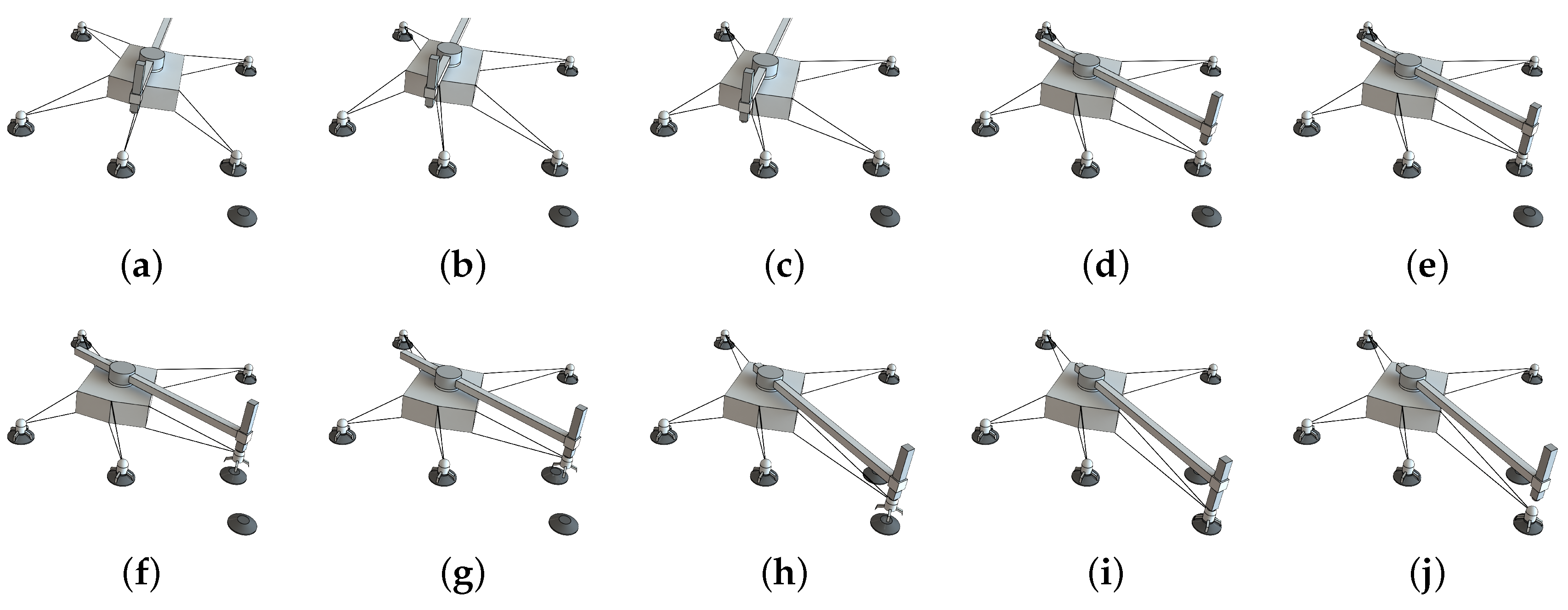
Figure 1a. For the path planning algorithm, these phases are further broken down into a sequence of nine motions separating the motion of the platform and arm, as also illustrated in
Figure 4:
- (a)
Initial state, all grippers are docked to a holding point and the platform is in the 10-cable configuration.
- (b)
Move the platform to a pose that is stable with eight cables and switch to the eight-cable configuration.
- (c)
Move the platform to a pose where the arm can reach the gripper to be picked. In the following, this is referred to as platform alignment.
- (d)
Move the arm’s end-effector over the gripper’s docking adapter.
- (e)
Dock the arm’s end-effector to the gripper’s docking adapter by approaching it in a straight line and slacken the cables of the gripper.
- (f)
Undock the arm’s end-effector and gripper from the hold by removing the gripper in a straight line.
- (g)
Move the platform to a pose where the arm can reach the hold to place the gripper.
- (h)
Move the arm’s end-effector and gripper over the hold’s docking adapter.
- (i)
Dock the arm’s end-effector and gripper to the hold’s docking adapter by approaching it in a straight line and tension the cables of the gripper.
- (j)
Undock the arm’s end-effector from the gripper by removing the end-effector in a straight line and switch to the 10-cable configuration.
The path planning algorithm treats each of these steps as a separate path planning task, where the final state of Tetherbot from the previous path planning task becomes the initial state of the following path planning task. As the motions of the platform and arm are separated, they can be treated as a traditional cable-driven robot and serial robotic arm, respectively. For both types of robots, a variety of algorithms for path and trajectory planning exist which simplifies the path planning problem. Here, we employ established methods, such as the A*-algorithm, which can be readily replaced by more advanced algorithms. Lastly, to further simplify the path planning, we assume an obstacle-free environment and negligible dynamic effects.
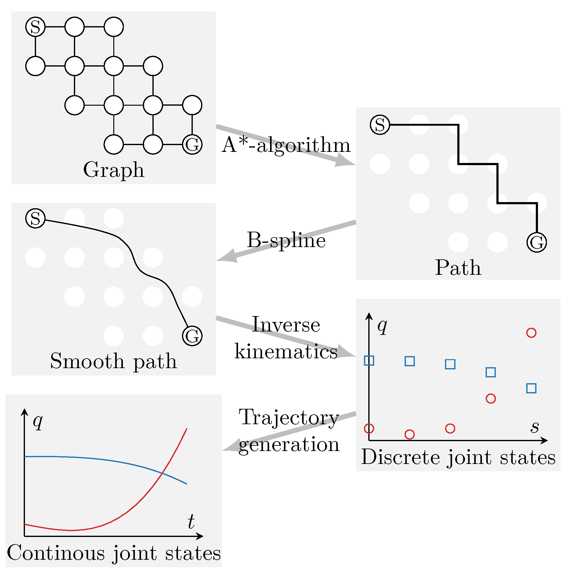
The path planning of both the arm and platform is based on a grid-shaped graph (
Figure 5). Every node of the graph represents a feasible pose
expressed as a vector of
x-,
y-, as well as
z-positions and yaw, pitch, and roll angles. Every edge represents the transition between two poses. The A*-algorithm [
27] is used to search for a path between the start and goal pose and it relies on a heuristic function
h to guide its search. Tetherbot’s path planning algorithm deploys different heuristic functions and goal conditions depending on the path planning task of each step in the motion sequence.
4.1. Platform
Each node of the platform’s search graph represents a feasible pose that satisfies the following conditions:
The capacity margin is larger than 0.
There are no self or obstacle collisions.
The cable lengths are within the set limits.
The static feasibility of a pose is traditionally evaluated based on the static equilibrium of the robot. However, this approach assumes a thorough understanding of the external forces and does not account for disturbances and discontinuous forces. To address this, we adopt the capacity margin (
11) as a measure of static feasibility. By considering a set of wrenches, we can incorporate disturbance forces that occur during interactions between the arm and the environment, abrupt changes in gravitational force when connecting or disconnecting the arm from a gripper, or dynamic forces. Here, we include all wrenches generated during the robot’s motion and the operation of the arm. This enables separate path planning for the arm and platform, as the state of the platform does not impose constraints on the motion of the arm, and vice versa.
Collisions of the robot with itself or obstacles can occur when moving the platform—although the latter is not yet considered. Tetherbot checks for collisions with itself—e.g., between the cables and the arm—using simplified convex bounding geometries and the Gilbert–Johnson–Keerthi algorithm [
28]. However, collision checks are not always necessary. For instance, in the case of Tetherbot, we have observed that checking for collisions between cables is unnecessary because the platform becomes unstable long before reaching a pose where such collisions could occur.
There are two path planning tasks for the platform: moving the platform to a pose that is feasible in the eight-cable configuration, and aligning the platform with the hold or gripper. In the first case, a preliminary workspace analysis is conducted to identify a feasible pose in the eight-cable configuration. The analysis samples poses arranged in a grid within the polyhedron formed by the grippers to evaluate their feasibility. If feasible poses are found, the one with the highest capacity margin is selected as the goal pose for the path planning. Then, path planning is conducted using the Euclidean norm (
12) to guide the A*-search towards the goal pose
. Once the platform reached the goal pose and the robot switched to the eight-cable configuration, the platform can be aligned to pick the gripper.
The alignment has to position the platform in a way that allows the arm to dock with the gripper. During the docking process, the arm initially maneuvers the end-effector to a position above the gripper before connecting the docking adapters in a straight-line motion whose end point is referred to as the docking point. The same applies when the arm places the gripper on a hold. Therefore, at the goal pose, specific conditions have to be fulfilled: both the start and the end point of the straight line motion must be reachable by the arm, and the direction of this motion must align parallel to the direction of movement of the second prismatic joint. We utilize the heuristic function
which factors in the distance between the platform position
and the docking point
as well as the angle
between the direction of the straight line motion and the direction of movement of the second prismatic joint. The specific docking point depends on the gripper to be picked or the hold where the gripper should be placed. The search halts once a pose is found that satisfies the aforementioned conditions.
4.2. Arm
When planning the arm’s motion, we consider a pose feasible if it meets the following conditions:
The goal of the arm path planning is to move the arm between various goal poses. Similarly to the platform, the Euclidean norm is employed as the heuristic function.
4.3. Trajectory Generation
The A*-algorithm outputs a sequence of poses which often forms a zig-zag-shaped path due to the grid nature of the graph. This necessitates smoothing of the path to prevent jerky motions of the robot. To achieve this, a third-order B-spline function is utilized to obtain a smoother representation of the path (
Figure 5). This path is then mapped from the coordinate space to the joint space for each joint following the kinematic equations detailed in
Section 3.1.
We apply a standard method [
29] that can be substituted by more advanced methods to obtain a trajectory. Initially, the spline functions of the joints are evaluated at arbitrarily chosen time intervals. The joint states of each time interval are connected with a third-order polynomial spline to form a continuous representation of the joint motion. The polynomial splines are evaluated at regular time steps, resulting in a sequence of joint states that can be translated back into poses for Tetherbot’s controller (see
Section 5.1).
5. Experiment
We conducted an experiment to demonstrate the feasibility of autonomous cable-driven climbing in a microgravity environment with sparse holding points. The experimental set-up consists of a prototype of Tetherbot which is placed in an environment with sparse anchor points. Gravity forces acting on the platform and arm are compensated to simulate a microgravity environment. To demonstrate autonomous cable-driven climbing, the prototype must autonomously plan and execute at least one step of its climbing locomotion, specifically planning and executing the relocation of at least one of its grippers, as illustrated in
Figure 4.
5.1. Prototype
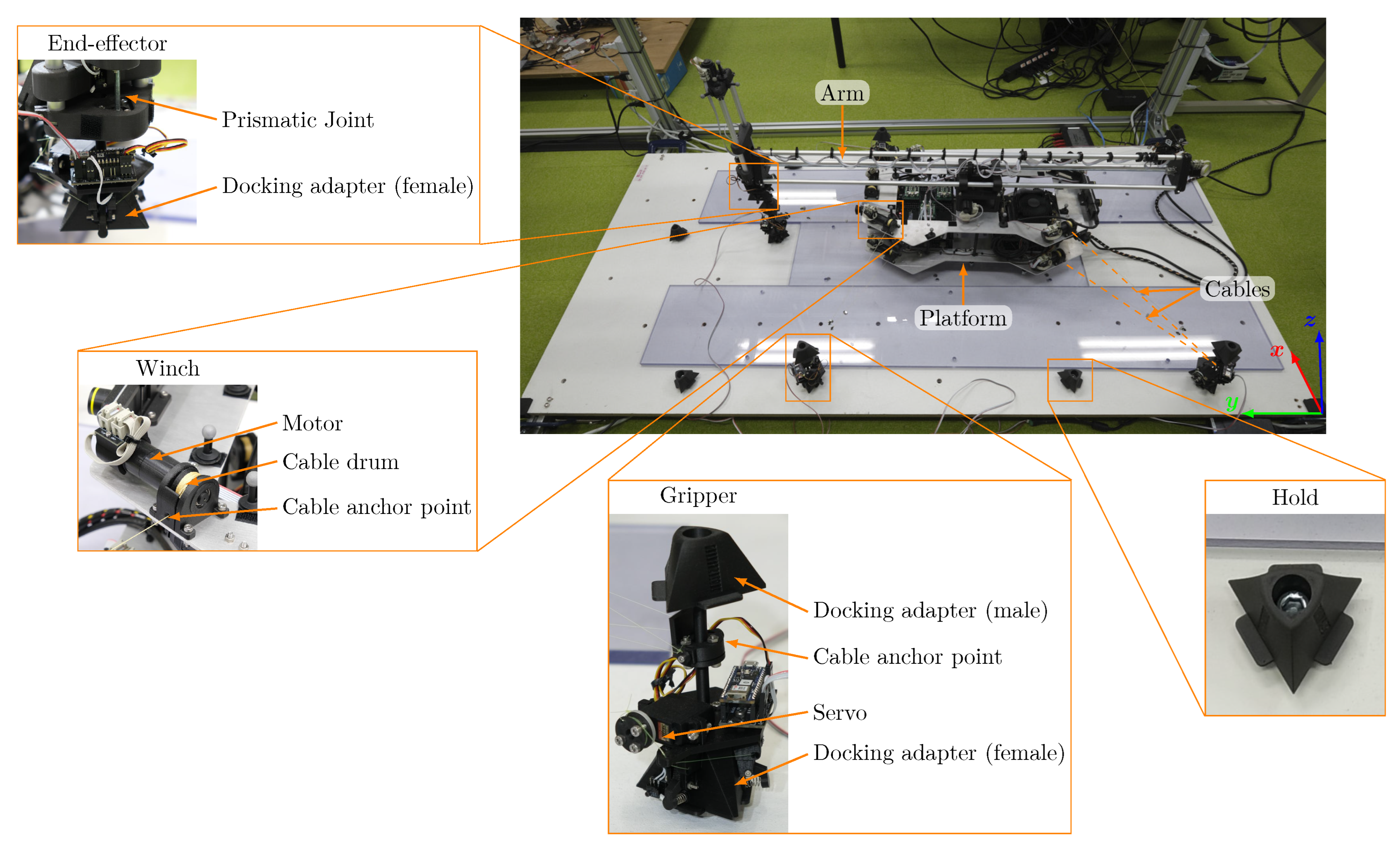
The prototype of Tetherbot is shown in
Figure 6. The design of the prototype is consistent with the design described in
Section 3.4 with ten cables and five grippers. The platform of the prototype measures roughly
cm excluding the arm. The arm’s first prismatic joint has a length of about 100 cm and the second of about 30 cm. The weight of the platform with the arm is about
kg.
The platform, in addition to the robotic arm, carries the on-board computer, motor controllers, and ten winches. Each winch consists of a motor, encoder, and gear-head assembly mounted to a cable drum. The cable is threaded through a small hole, forming the kinematic cable anchor point. The arm consists of a revolute joint and two prismatic joints. These joints are powered by motor, encoder, and gear-head assemblies. The revolute joint features an additional worm gear to maximize torque. The prismatic joints use lead screws to convert the rotational output of the motors into linear motion. Connected to the last prismatic joint is the end-effector of the robotic arm. Docking adapters connect the end-effector of the arm to the grippers and the grippers to the holding points. The docking adapters consist of a male and a female part. When pushed together, spring-loaded pawls on the female part engage with teeth on the male part, forming a fixed connection. A servo motor is used to disengage the pawls and open the connection. For the connection between the end-effector and the gripper, the female part is on the end-effector side and the male part on the gripper side. For the connection between the gripper and the hold, the female part is on the gripper side and the male part forms the hold itself. The gripper consists of the docking adapters and the cable anchor point. The cables are connected to two sides of a disk that freely rotates around the main axis of the gripper. This design ensures that the kinematic cable anchor point lies on the main axis, meaning it remains fixed regardless of the gripper’s orientation on the hold.
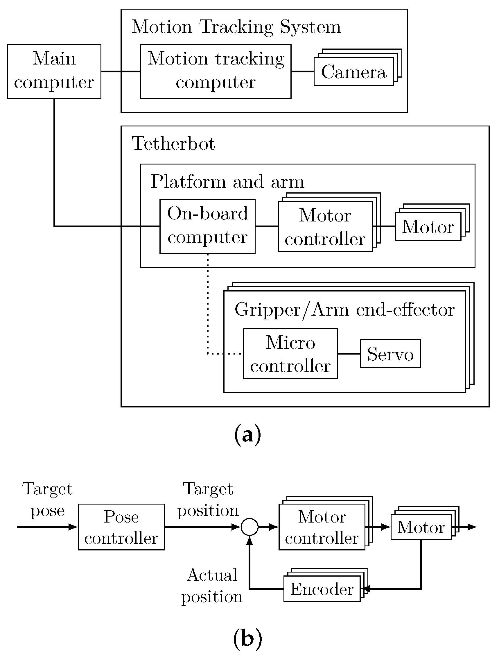
The control system is comprised of a main computer, a motion tracking system, and the prototype, as depicted in
Figure 7a. The main computer provides a user interface for the human operator and performs path planning, trajectory generation, and data acquisition. A motion tracking system by OptiTrack measures the robot’s pose and calibrates the length of the cables. The on-board computer of the prototype receives the target trajectory from the main computer. It runs an open-loop pose controller (see
Figure 7b) that translates the target poses of the trajectory into target positions for the motors. These target positions are sent to the motor controllers, which operate a closed control loop using the motor encoders as feedback sensors. Additionally, the on-board computer sends commands to open or close the docking adapters on the grippers and the arm’s end-effector via a wireless connection based on the Bluetooth Low Energy (BLE) standard.
5.2. Environment
Simulation of microgravity requires gravity compensation for the prototype. Compensating gravity in three-dimensional space while retaining all degrees of freedom of the platform and arm is very complex due to the multiple parts of the robot moving relative to each other. Thus, to simplify the experiment, it is conducted in a quasi-two-dimensional environment. The environment, depicted in
Figure 6, consists of a flat, level surface with holding points mounted to it. To compensate gravity, the platform is embedded with ball casters on the surface while the arm’s first prismatic joint is suspended from a free-moving crane. This restricts the motion of the Tetherbot’s platform to rotation and translation within a single plane while allowing the arm to move in three-dimensional space to reposition the grippers. The remaining friction force to move the platform on the surface is less than 2 N. This is taken into account by the task wrench set selected for the experiment, which is
.
5.3. Procedure
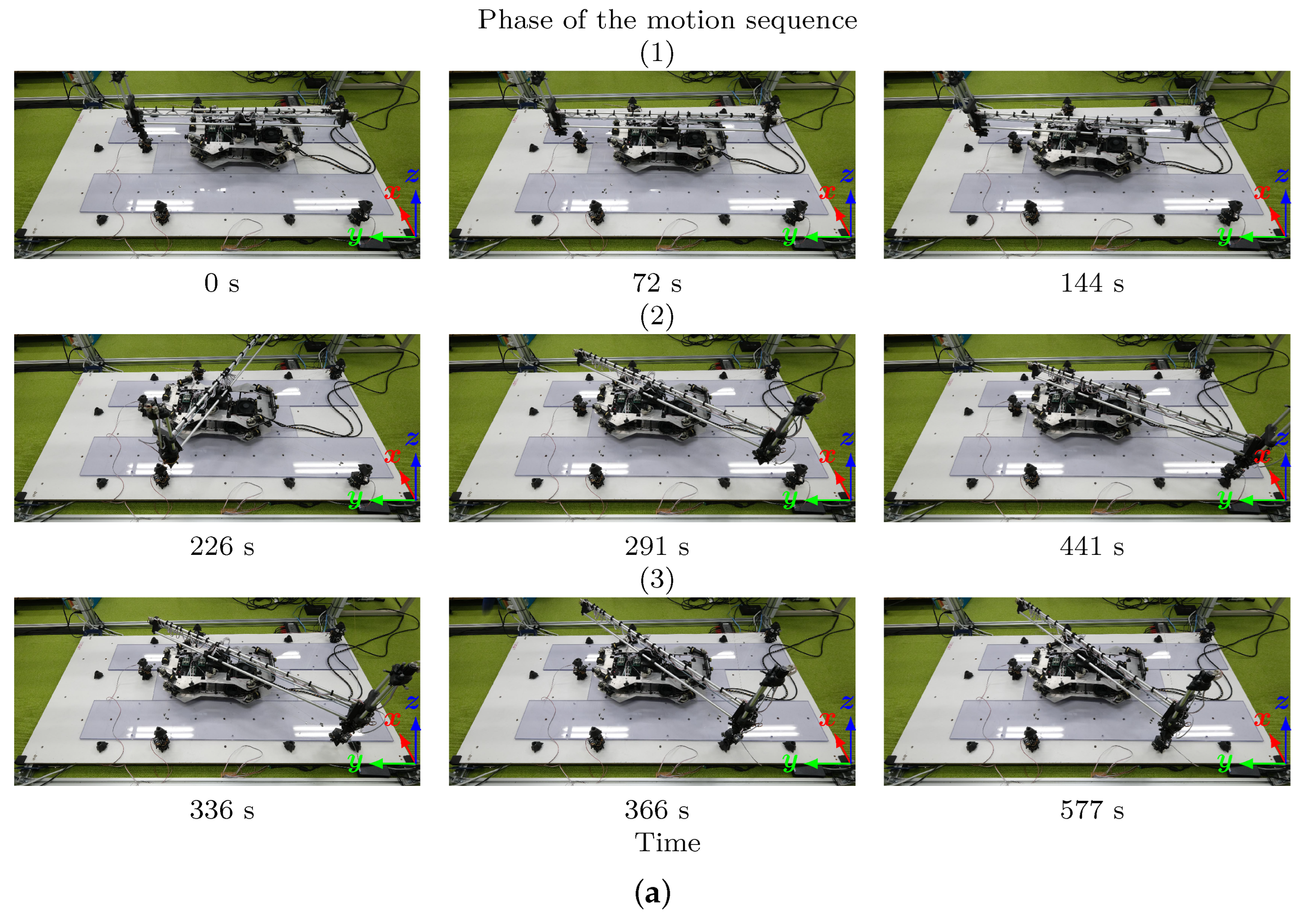
At the beginning of the experiment, Tetherbot’s platform is placed in a feasible pose on the surface and the grippers are placed on the initial holding points, as shown in
Figure 8a, at 0 s. The cables are manually tensioned and their initial length is determined based on the platform pose measured by the motion capture system and the position of the holds. The operator executes the path planning algorithm to pick and place a gripper. The motion data are reviewed and transmitted to Tetherbot. Tetherbot then executes the motion autonomously.
5.4. Results and Discussion
The results of the experiment are summarized in
Figure 8.
Figure 8a shows images of the prototype picking and placing the gripper. The
x-,
y-, and
z-axes of the world coordinate frame are indicated by red, blue, and green arrows, respectively, as also shown in
Figure 6.
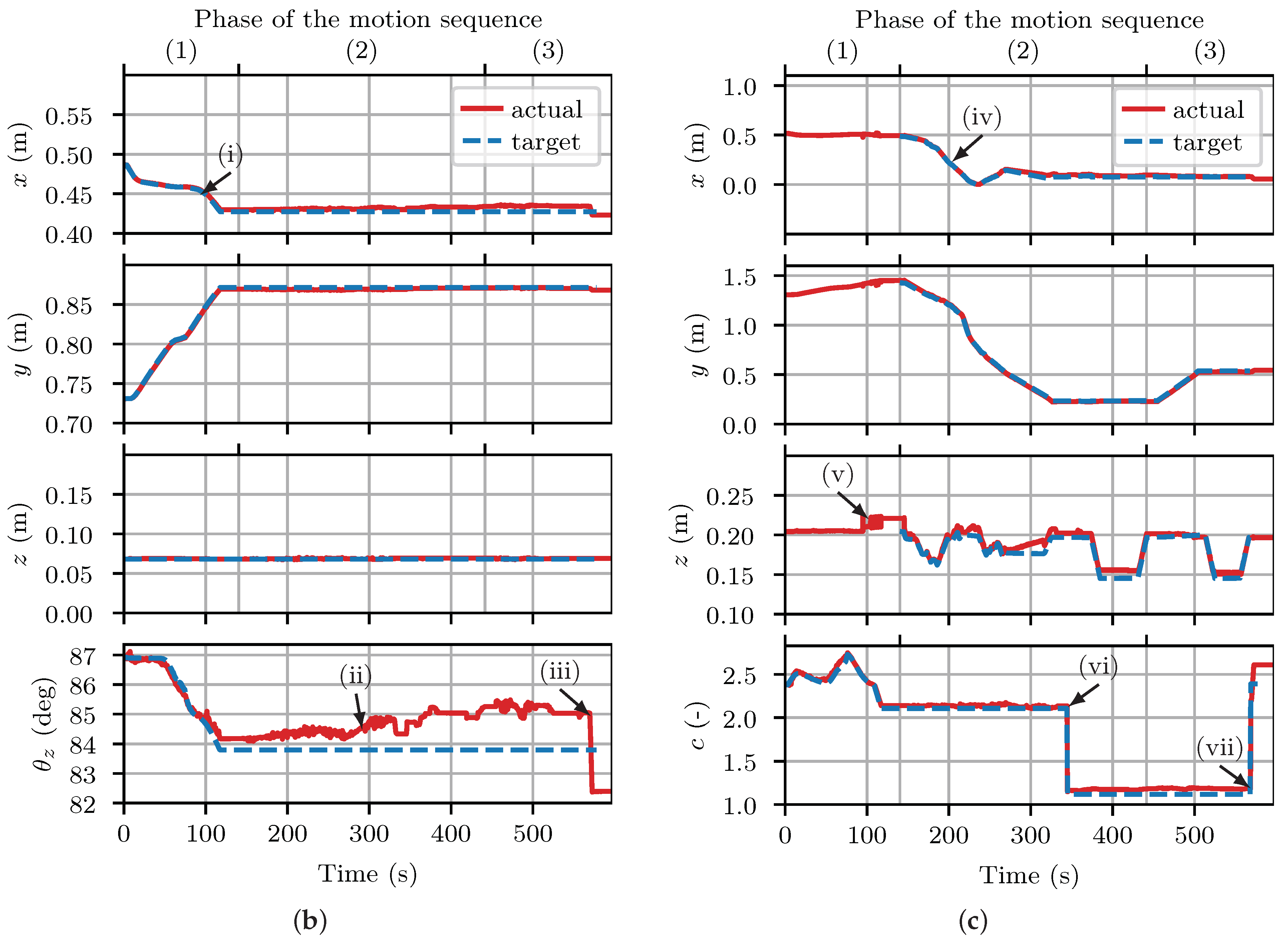
Figure 8b,c show target and actual pose data and the capacity margin with respect to time and phase of the pick and place motion sequence (moving the platform (1), picking the gripper (2), and placing the gripper (3)). The target data is based on the trajectory output by the path planning algorithm and actual data on measurements of the motion tracking system.
The results indicate that Tetherbot’s prototype successfully picked and placed the first gripper. The duration required to complete the pick and place motion was approximately 8 min excluding periods where the prototype was not moving. The platform’s actual pose followed the target pose closely (
Figure 8, (i)). Deviations from the target pose occurred due to disturbances caused by the arm’s motion (ii). The most significant deviation occurred during the transition from the 8- to the new 10-cable configuration (iii) when tensioning the cables. Note that the platform did not have to perform any alignments, as the pick and place motion with the arm could be performed from the current pose. The arm’s end-effector also followed the target pose well (iv). Target pose data are available from the beginning of phase 2, as the controller of the arm is activated only after the first phase. The arm’s
x- and
y-position accuracy was only minimally impacted by the platform deviations as the inverse kinematics of the arm use the actual pose of the platform at the beginning of each motion, preventing the accumulation of position errors over time. The
z-position had more substantial errors, which resulted from disturbances in the crane set-up. Moreover, the position data of the arm exhibit temporary instabilities during the first phase, visible as jumps in the graph (v). These can only be attributed to the tracking instabilities of the motion tracking software, for example, due to marker occlusion, as no instabilities are present in the platform
z-position data or the video data and the arm controller is no yet activated in the first phase (the joints of the arm maintain their position). Once the pick and place is complete, the pose data of the platform and arm remain stable, indicating that no significant vibrations were induced during the motion. This is expected, given the robot’s low motion speed and dampening forces applied by the gravity compensation to the prototype.
The capacity margin remained positive throughout the experiment, indicating that the platform always could withstand the wrenches of the assumed wrench set. The actual values are very similar to the target values, suggesting that the previously mentioned pose errors of the platform did not significantly affect the capacity margin. Notably, the capacity margin shows distinct jumps whenever a cable is slackened (vi) or tensioned (vii).
Following the initial pick and place motion, we proceeded with the remaining grippers to complete the gait. The execution of the gait was successful, with both the path planning algorithm and the prototype performing without major issues. On two occasions, there were minor issues with the grippers’ docking adapter failing to engage properly, which required human intervention. These issues were purely mechanical and unrelated to the path planning. The average duration of each pick and place motion was about 8 min and the achieved climbing speed in the y-direction was about cm/min.
6. Conclusions
In this paper, we provided the first successful demonstration of cable-driven climbing in an environment with sparse anchor points through a real-world experiment. To achieve this goal, we presented Tetherbot, the first cable-driven climbing robot with a redundantly constrained configuration of cables. We discussed its design, kinematics, and statics and provided a path planning strategy for relocating Tetherbot’s grippers, thus enabling cable-driven climbing. The experimental validation fills a crucial gap in the existing literature, indicating that cable-driven climbing is a viable concept for its intended application—climbing on structures in space like space stations and satellites and carrying out maintenance and manufacturing tasks.
In the future, we will expand on the path planning and validation of Tetherbot. Regarding the path planning, improvements have to be made in the pick and place motion sequence. For example, when the platform moves to a pose that is stable with eight cables to switch the cable configuration and then aligns the platform to pick the gripper, the platform may perform unnecessary back and forth movements. These should be avoided given the energy constraints of a space mission. Further improvements include the implementation of more advanced algorithms for the graph search and trajectory generation. Regarding the validation, future experiments should focus on climbing in three-dimensional environments such as the exterior of a space station. For this purpose, Tetherbot’s prototype needs to be further refined e.g., by moving from external sensors to on-board sensors and switching from open-loop to closed-loop controls.
