Abstract
Creating an adult-sized humanoid robot with stable walking capabilities is a major challenge in robotics. While many renowned research groups focus on robots for perilous work environments and precision tasks, our approach simplifies balance control, making it accessible to robotics research groups and educational institutes. This facilitates the development of complex functionalities such as vision and object manipulation for adult-sized humanoids. This research article introduces RoboMan II, an advanced version of RoboMan I, which won the most prestigious award in all humanoid robot leagues at RoboCup 2016 due to its exceptional performance in walking and playing soccer. RoboMan II features significant improvements in performance, inherent stability, recovery after falls, and balance control. To facilitate its development, RoboMan II is lighter and incorporates a modified foot and parallel structure for its leg to boost its inherent stability, along with a two-stage balance control system for Immediate Response and Gradual Adaptation, enhancing its adaptability in various environments. Our simulation results demonstrate that RoboMan II’s walking stability on flat surfaces improved significantly in the face of minor perturbations, with the number of steps within the stable region increasing from 24%, with only the immediate controller to 58% when both controllers were used. Similar improvements were observed on inclined surfaces. Additionally, the 3D CAD files for all of the robot parts are released as open source in conjunction with this paper to facilitate reproduction and further innovation. The forthcoming RoboMan III will incorporate custom servo motors for increased speed, torque, and enhanced fall recovery, preventing disengagement of the gear box after a fall. It promises to be an invaluable asset for research and practical applications in humanoid robotics.
1. Introduction
Rapid advancements in robotics have paved the way for humanoid robots designed to mimic human forms and behavior. These robots hold immense potential in fields such as healthcare, education, entertainment, and domestic assistance, performing tasks that are dangerous, too precise, or monotonous for humans, thus improving safety and efficiency. The design and development of humanoid robots is quite challenging and involves interdisciplinary collaboration, encompassing mechanical engineering, computer science, artificial intelligence, and cognitive science.
Humanoid robots are distinguished by their human-like appearance and their ability to interact with their environment and humans naturally. This interaction is facilitated by advanced sensors, actuators, and control algorithms that enable the robot to perceive, process, and respond to stimuli. Early prototypes, such as Honda’s ASIMO, demonstrated the feasibility of creating bipedal robots capable of walking and performing simple tasks [1]. Since then, significant progress has been made in enhancing the mobility, dexterity, and autonomy of humanoid robots. In 2008, Toyota Group presented the HRP-3 humanoid robot. HRP-3 is designed to resist dust and moisture, with improved wrist and hand mechanics for better manipulation [2]. NASA and General Motors developed Robonaut 2 (R2), which arrived at the International Space Station in early 2011. R2 features improved force sensing, motion range, bandwidth, and dexterity [3]. In 2012, PETMAN, developed by Boston Dynamics, was a humanoid robot designed to test chemical protective clothing. It evaluates Individual Protective Equipment (IPE) in a controlled environment, exposing it to chemical agents while walking and performing exercises. Equipped with sensors and temperature control, PETMAN simulates human physiological conditions, including sweating [4]. A lot of research has been conducted on the ATLAS humanoid robot, such as a study on optimization algorithms for planning, control, and state estimation in bipedal robots for complex environments [5], and another study introducing algorithms to improve humanoid robot balance by adjusting step timing and foot placement [6].
Over the years, various humanoid robots have been designed and showcased in different competitions and exhibitions. For instance, in the RoboCup International Competition 2009, the Darmstadt Dribblers team designed a kid-sized soccer humanoid robot with low-level control software that generates stable walking motions in real-time using Inverse Kinematics and ZMP theory [7]. Another team, NimbRo Humanoid, designed Dynaped, a teen-sized robot measuring 105 cm in height and weighing 7 kg [8]. Dynaped uses parallel kinematics with EX-106 actuators and is built from a carbon composite and aluminum, controlled using a hierarchical framework managing reactive behaviors at various levels.
In 2013, Team CHARLI introduced a robot representing a significant step in humanoid soccer robots. Unlike most legged robots that use the energy-inefficient static stability criterion, CHARLI explores dynamic walking, where the center of mass moves outside the support polygon, mimicking human walking. Dynamic stability is measured using the Zero Moment Point (ZMP) to optimize and control gait stability [9]. After that, a team introduced a closed-loop control system that extends the ZMP-based approach with a Linear Inverted Pendulum Plus Flywheel Model (LIPPFM) and a Linear Quadratic Regulator (LQR) to enable stable walking on uneven terrain by dynamically adjusting the robot’s balance and movements [10,11]. A year later, Team HuroEvolution designed a humanoid robot with a parallel leg structure. While the robot was very stable, it was also quite heavy and slow [12].
In 2015, we developed the first version of our humanoid robot (RoboMan I) designed using a parallel structure and external gears in the yaw and roll axes, improving the power needed for walking. We used Dynamixel MX-106 (Corona, CA, USA), servo motors for this design [13]. In the 2015 competition, Team THORwIn, a collaboration between the University of Pennsylvania and the University of California, Los Angeles, secured first place in the soccer matches, while our team achieved first place in the technical challenges, including high kicks and jumping [14].
Over the last five years, humanoid robots like Sweaty, HERoEHS, and Team ROMELA using the ARTEMIS robot have focused on soccer humanoid robotics competitions [15,16,17]. In recent years, the best adult-sized humanoid robot has been the NimbRo robot, known for its stable walking algorithms and high-performance balance control, with ongoing work on team communication between robots [18].
Beyond the competitive arena, several commercial humanoid robots have made significant strides in various industries. Notable examples include Boston Dynamics’ Atlas (Waltham, MA, USA), known for its advanced mobility and agility in complex environments. Other significant contributions include Optimus by Tesla (San Carlos, CA, USA), designed for general-purpose tasks, Figure, aimed at assisting with human tasks (Sunnyvale, CA, USA), and Unitree’s humanoid robots, which emphasize affordability and practical applications (Hangzhou City, China). To prototype and manufacture these robots, different production methods such as milling, 3D printing, laser cutting, sheet metal bending, welding, and casting are employed, as it is crucial to have consistent and rigid parts that are lightweight in humanoid robot design. These robots are being utilized in customer service, healthcare, and research, showcasing the broad applicability and commercial viability of humanoid robotics technology. The ongoing development and deployment of these commercial robots highlights the growing impact of humanoid robots on everyday life and their potential to transform various sectors.
In addition, there are several educational humanoid robots in this field that provide a platform for testing walk and control algorithms. In a study conducted in 2008, Bioloid was introduced as an educational robotic kit using modular DC servos to build various robots [19]. Following that, a collaboration between the University of Tokyo and Virginia Tech University resulted in a new open platform kid-sized humanoid robot named DARwIn-OP, which was faster and more stable [20]. In 2013, ALDEBARAN ROBOTICS designed and manufactured a standard platform humanoid robot to launch a new league in RoboCup international competitions [21]. While existing educational platforms are typically kid-sized (from 40 cm to 100 cm tall) due to the reduced complexity in walking and control algorithms, we have developed an adult-sized robot (from 100 cm to 200 cm tall) that more accurately replicates human dynamics and presents greater challenges in stability and control. To address these complexities, we designed a robust structural framework combined with an innovative control algorithm that enhances the robot’s dynamic stability, making it suitable for advanced educational and research applications.
Our goal in developing RoboMan I was to create a robot that not only matches human adult size, but also excels in environments and applications where traditional educational robots fall short. RoboMan I achieved the most important award in all humanoid robots leagues in RoboCup 2016 (Best Humanoid award) because of the significant performance that it had in walking and playing soccer [22]. Here, we introduce the second version of RobMan (RoboMan II). In this version, we focused on reducing weight, improving the inherent balance and control system, and increasing the parts’ rigidity to enhance the robot’s speed and stability, particularly for dynamic activities such as playing soccer. Ultimately, the design of RoboMan II seeks to provide a platform for advanced functionality and robust performance that facilitates research in this arena.
- RoboMan I prominent features:
- Adult Size: Our robot was almost human adult size, unlike smaller robots such as the Darmstadt Dribblers, DARwIn-OP, and Dynaped.
- Low Weight: Our robot was designed to be as lightweight as possible, surpassing robots like CHARLI and THORwIn, to support our fast-walking algorithm.
- Stability and Performance: Parallel actuators enabled a stable, fast walking system using variable P-Gains for smoother strides. Figure 1 shows RoboMan I kicking during the RoboCup international competitions.
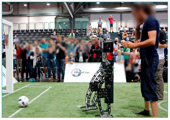 Figure 1. RoboMan I adult-sized humanoid robot kicking a ball during a RoboCup 2016 soccer match.
- RoboMan II design criterea:
- Reducing weight: One of the most crucial reasons for developing RoboMan II is reducing the weight of the robot, as the humanoid’s agility and balance heavily depend on it. These are particularly beneficial for playing soccer. Roboman II is very lightweight in comparison to robots that participated in Robocup2024, like ARTEMIS and HERoEHS.
- Improving inherent balance will allow for the development of various control algorithms for walking, kicking, and other motions required for soccer, ensuring stability and performance.
- Sitting capability: Redesigning RoboMan I’s lower limbs to allow for sitting posture, standing up when the robot falls or interacts with the objects on the ground.
- Improving the Gearbox: Utilizing the 34 gearbox, RoboMan I’s performance was highly dependent on its components. To enhance durability, reliability, and precision in power transmission, we developed a custom homegrown gearbox, improving upon the off-the-shelf gearboxes used in RoboMan I. Additionally, the off-the-shelf gears (Dynamixel MX-106) occasionally disengaged during falls, leading to a condition equivalent to joint dislocation. Our homegrown gearbox aims to resolve this issue, ensuring consistent performance even after falls.
- To improve balance control, we aimed to enhance stability in response to perturbations and changing environments, thereby ensuring more stable walking and powerful kicking in soccer games.
2. Methods
As shown in Figure 2, there are 8 servo motors in the robot’s knee, each with set of 4 servos synchronized. Four of these servos move the ankle in the pitch axis, as indicated by green signs, while the other four move the hip in the pitch axis. We also have four unactuated joints in the robot ankle, marked with green signs in the figure. Additionally, there are two servo motors in the hip for hip roll movement, employing external gears with a 2:1 ratio, making this joint more powerful. Two other servos control the ankle roll movement in the same manner. Another servo motor in the hip controls the hip yaw motion, also utilizing gears with a 2:1 ratio.
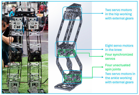
Figure 2.
RoboMan II adult-sized humanoid robot’s legs are designed with three main sections: ankle, knee, and hip. The thigh and shin parts are designed to help the robot sit.
2.1. Improving RoboMan’s Mechanical Structure
2.1.1. Decreasing Weight
The RoboMan I humanoid robot weighed approximately 16 kg, which was already a low weight for an adult-sized robot compared to others. However, by modifying the upper-body structure, reducing the thickness of the parts, and using aluminum (instead of steel), titanium, and PLA for all of the mechanical components, the weight was reduced to 13.5 kg. This 13.5 kg weight is remarkably low, considering the robot’s 148 cm height and the inclusion of 34 Dynamixel actuators with a total weight of approximately 5.5 kg.
2.1.2. Improving Inherent Balance
We improved the design of the foot to be more rigid, which enhances the accuracy of the robot’s steps. To achieve this, we switched from laser cutting and bending to CNC milling. This manufacturing method reduces the bending and deformation of the footplate, creating a uniform and rigid structure that facilitates balance control. The combination of a lightweight design and a more rigid foot plate helps the robot maintain stability during kicking.
We use a parallel mechanism for the robot legs to increase stability during walking. The purpose of designing a robot with a parallel mechanism in the leg at this size is to ensure inherent mechanical stability even before the development of balance control algorithms. The inherent stability of the parallel mechanism simplifies the initial stages of development, making it easier to achieve smooth and reliable movement. Once these fundamental aspects are optimized, users can shift their attention to enhancing other software components of the robot, such as the robot’s vision and behavioral algorithms.
2.1.3. Sitting Capability
We changed the robot’s thigh and shin design, as shown in Figure 3, to help the robot transition from a sitting posture to standing up when it falls. Figure 3a shows the RoboMan I thigh and shin parts, which are curved and prevent the robot from sitting. Figure 3b shows the RoboMan II thigh and shin parts, which allow the robot to sit easily.
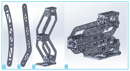
Figure 3.
(a) RoboMan I thigh and shin parts. (b) RoboMan II thigh and shin were designed to help the robot sit. (c) RoboMan II entire leg in standing position. (d) RoboMan II entire leg in sitting position.
2.1.4. Optimized Servo Motor BST-15
Servo motors, especially those with low weight and high torque, like Dynamixel servo motors, play a critical role in various sizes of humanoid robots, including our robot design. Previously, our robots utilized Dynamixel MX-106 servo motors. However, we have now designed a more efficient and cost-effective servo motor, which we will soon integrate into our robots. In Figure 4, the Dynamixel MX-106 is shown on the left, while our new servo motor, called “BST-15”, is on the right. Table 1 provides a comparison of the configurations of both servos.
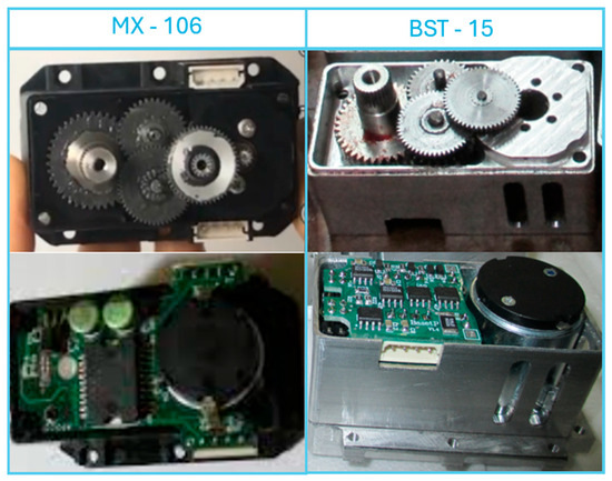
Figure 4.
MX-106 servo motor gearbox and electronics circuit on the left, and BST-15 servo motor gearbox and electronics circuit design on the right.

Table 1.
Comparing two servo motors specifications.
The mechanical design of our servo motor has been significantly enhanced by producing all body parts from aluminum, providing the necessary strength and durability for dynamic applications. Additionally, we designed and manufactured compound gears to ensure precise movement without unwanted rotation between gear components. In other servomotors, compound gears are usually pressed into each other (as seen in Figure 5a), causing issues when subjected to high torque, with two gears rotating into each other. We have resolved this problem by using keyed spur gears. A key is used on a shaft keyway to retain mechanical power transmission components such as gear drives and pulleys, ensuring reliable power transmission (as shown in Figure 5b).
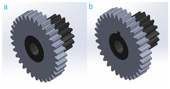
Figure 5.
(a) Simple gears pressed into each other. (b) Keyed gears assembled using a key to create a compound gear.
By increasing the gear ratio from 225:1 to 240:1, we have improved the mechanical advantage, resulting in an increase in stall torque. Moreover, by redesigning the electronic components, we now recommend a voltage of 14.8 V instead of 11.1 V, which further boosts the stall torque from 8.4 N·m to 9.6 N·m, and No-load speed was increased from 45 rpm to 58rpm. These improvements contribute to the servo motor’s superior performance, making it ideal for applications requiring high stability and power, such as humanoid robots.
The BST-15 servo motor operates at a high speed, operates within a voltage range from 10 to 18.5 volts, and is equipped with RGB LEDs for status indication and user control. It employs a switching power supply for its internal circuitry to minimize power loss and enhance efficiency. The motor uses an RS-485 Half-Duplex port, supporting up to 128 devices on the network, and includes internal protection with TVS for the RS-485 port. A current sensor is integrated for motor current control, and it also reads the motor’s input voltage. The electronics are divided into two separate boards: one for processing, switching power supply, encoder sensor, RS-485 port, status LED, and temperature sensor, and the other for the motor driver, MOSFETs, and current sensor. To boost motor speed, a powerful Maxon motor was selected, and the motor voltage was increased, extending the input voltage range to allow for performance adjustments as battery energy decreases. The use of a switching power supply reduces power loss, lowers internal temperature, and decreases board power consumption, which is particularly beneficial when multiple motors are used. Precision is ensured with a digital sensor offering a 12-bit resolution (0.0879 degrees) for accurate motor position measurement. Figure 6 illustrates a model of the BST-15 servo motor.
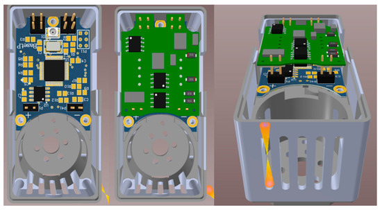
Figure 6.
Three-dimensional model of the BST-15 servo motor with two separate electronic circuits, assembled on top of each other due to the limited available space.
2.2. Robot’s Electronics
Our robot utilizes two controllers: one for high-level processes such as image processing, and another for low-level tasks like controlling and synchronizing actuators at each joint during walking and balance control algorithms. Figure 7a depicts the model of the low-level controller and power controller board. The low-level controller, using a BeagleBone Black running the Ubuntu operating system, handles all of the necessary sensor and actuator data, making it available to the main controller via an Ethernet communication interface using the UDP protocol for uninterrupted and fast response [23].
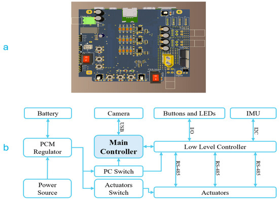
Figure 7.
(a) Robot’s low-level controller and power board designed. (b) Electrical design diagram of our robot.
Using Ubuntu, a non-real-time operating system, for the low-level controller facilitates easier and faster software development and debugging. However, it has the drawback of not being able to control half-duplex RS-485 direction pins in real-time, which is essential for achieving high communication speeds with actuators. To address this issue, we employ the MAX13488E IC [24], which automatically manages direction control in real-time.
As shown in Figure 7b, to achieve the fastest communication speed with actuators, we use three individual RS-485 ports: one for each leg, and one for the upper-body joints. This configuration is necessary because a single bus cannot efficiently communicate with numerous actuators.
3. Control
3.1. Gait and Balance System
RoboMan II humanoid robot’s gait and balance system is meticulously designed to emulate human walking patterns, employing advanced methodologies to ensure stability, agility, and energy efficiency. This section delineates the core components of our gait and balance system, emphasizing Inverse Kinematics calculations, sinusoidal trajectory generation, Dynamic Gait Frequency Adjustments, and robust balance control mechanisms.
3.1.1. Inverse Kinematics Calculation
Inverse Kinematics (IK) is crucial for determining the necessary joint angles to achieve a specified foot position. By assuming equal lengths for the thigh and shin, the IK for the robot’s legs can be derived using the following equations:
where x and y are the coordinates of the desired foot position, l represents the length of the thigh and shin, q1 is the hip joint angle, and q2 is the ankle joint angle as it shown in Figure 8.
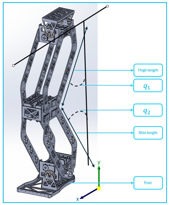
Figure 8.
q1 is the robot hip joint angle and q2 is the ankle joint angle, which are the angles that the thigh and shin are making along the Y axis.
3.1.2. Sinusoidal Trajectory Generation
To create natural and smooth walking patterns, we use sinusoidal functions to define the foot movements in vertical (y-axis) and horizontal (x axis) planes. These trajectories facilitate fluid and human-like walking. The formulas for the sinusoidal trajectories are as follows [25]:
The vertical motion of the foot, represented by z(t), follows a sinusoidal pattern.
So, z(t) describes how the foot moves up and down (lifting off the ground and placing it back down). is the amplitude (maximum height) of the foot’s lift, controlling how high the foot goes with each step. ω is the angular frequency, which determines how fast the robot steps. t represents time.
The forward and backward motion of the foot, represented by x(t), is also sinusoidal.
x(t) describes the horizontal movement in the sagittal plane. is the amplitude, which controls the length of the step (how far forward or backward the foot moves). is the phase shift, which adjusts the starting point of the sine wave. This phase shift allows for the robot to synchronize its foot movements between different legs or adjust for different walking styles.
The side-to-side motion of the foot, represented by y(t), follows another sinusoidal function.
y(t) describes the horizontal movement in the lateral plane, which is essential for balance, especially when the robot shifts weight from one foot to the other. Ay controls the sidestep distance. is the phase shift for the side-to-side motion, allowing for synchronization with the other axes.
To maintain stability, especially when walking, the robot’s center of mass (CoM) also follows a sinusoidal path.
describes how the robot’s overall center of mass moves laterally to maintain balance. is the amplitude for the CoM movement, which controls how much the robot sways from side to side to keep balanced. is the phase shift for the CoM trajectory, ensuring that the CoM moves in coordination with the foot placements.
3.1.3. Dynamic Adjustment of Gait Frequency
The gait frequency, or steps per second, is dynamically adjusted according to the robot’s task requirements. Adjusting the gait frequency is important because different tasks require different walking speeds. For example:
- Higher Frequencies: When the robot needs to perform quick actions, like dribbling a ball or rapidly changing direction, it needs to take faster steps. This means a higher gait frequency, which gives the robot more control and responsiveness.
- Lower Frequencies: For regular walking, especially over longer distances, slower steps are more efficient. This helps the robot conserve energy and maintain stability, making walking smoother and less tiring for the robot.
To adjust the gait frequency dynamically, we use an Inverted Pendulum Model. This model helps us understand how the robot’s center of mass (CoM) moves like a pendulum swinging back and forth. The idea is to optimize the robot’s movements to maintain stability while minimizing energy use.
Using the Inverted Pendulum Model, we can solve for Ay,CoM from the given gait frequency f:
where θ is the angle of displacement, l is the leg length, and g is the gravitational constant. The angle θ is derived from the period T using this equation:
This equation allows us to calculate θ if we know the period T. Knowing θ helps in determining how much the robot needs to sway its body to maintain balance while walking.
3.1.4. Robust Balance Control
Maintaining balance in real-world conditions requires robust control systems to handle uneven terrain, sensor noise, motor delays, and external disturbances. Our robot employs two complementary control loops: an Immediate Response Loop for rapid adjustments, and a Gradual Adaptation Loop for more extended adjustments. The control diagram illustrating these loops is shown in Figure 9.
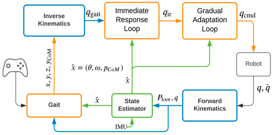
Figure 9.
Control diagram illustrating the Immediate Response Loop and Gradual Adaptation Loop for maintaining balance in the humanoid robot. The robot sends joint positions and velocities to the Forward Kinematics module, which determines the feet positions relative to the robot’s body. These data, along with IMU readings, are sent to the state estimator to calculate the robot’s center of mass (CoM, pCoM), orientation (θ), and angular velocity (ω) as the state vector (). The Gait Module processes the state and feet positions and uses sinusoidal formulas to generate the desired trajectories for each foot and the CoM trajectory (YCoM). This information is then used in Inverse Kinematics to determine joint positions, which are fine-tuned through the Immediate Response Loop and Gradual Adaptation Loop before sending the command positions (qcmd) to the motors. Both control loops take the state vector () and apply adjustments to the joint values to maintain the robot’s balance.
Immediate Response Loop: This loop operates at high frequency to provide immediate adjustments to the robot’s posture and joint angles in response to sudden disturbances, such as impacts or rapid terrain changes. Within this loop, we implement IMU-based balance control.
An Inertial Measurement Unit (IMU) sensor monitors the robot’s orientation and linear acceleration, providing data to adjust the robot’s arm and ankle movements to counteract destabilizing forces. Using a Proportional-Derivative (PD) controller, the robot dynamically adjusts joint angles to stabilize itself based on the IMU data. The angular velocity (ω) from the state estimator is directly multiplied by a configurable gain factor for the PD controller. These gain factors are tuned manually to achieve the best control response. The formula for this control is:
where qir represents the immediate response joint angles, qgait represents the gait joint angles, kp and kd are the proportional and derivative gain factors, θ is the current orientation angle, θdesired is the desired orientation angle, and ω is the angular velocity.
Another control method involves adjusting the amplitudes for the x and y trajectories, which define how fast the robot walks along those axes. This method calculates the acceleration feedback based on the θ and ω terms and converts this acceleration using the gait frequency (f) and amplitude adjustments (Areduction) to alter the stride size [26]. The formula for this control is:
where Areduction is the adjustment to the stride amplitudes used as a subtraction to the amplitudes Ax and Ay in the sinusoidal trajectories. ka and kω are gain factors for the acceleration and angular velocity feedback, respectively.
Gradual Adaptation Loop: Operating over longer time windows (2–10 s), this loop makes gradual adjustments based on extended sensor data analysis. It addresses long-term shifts in the robot’s center of mass (CoM) and gradual environmental changes. Within this loop, we implement Comprehensive Balance Maintenance.
The robot uses direct kinematics and motor position readings to calculate the CoM relative to the foot on the ground. Adjustments to the arm and ankle positions guide the CoM back to the optimal location, ensuring long-term stability even on uneven terrain or with varying battery performance. We are aware that battery voltage can affect the robot’s performance during play and that the terrain might have slopes in certain areas. These are not rapid but gradual changes, which need consistent correction. For example, the robot on a slope needs to consistently apply correction terms to the arms and ankles to obtain the CoM at the desired location, regardless of the terrain situation. The adjustments can be represented as:
where qcmd are the command joint angles, qir are the initial joint angles, kcorrection and kθ are correction gain factors, pCoM is the current CoM position, pdesired is the desired CoM position, θcurrent is the current orientation angle, and θdesired is the desired orientation angle.
4. Results
To validate our control algorithms, we conducted several experiments to assess the robot’s stability under various conditions. To quantify stability, RoboMan II’s center of mass (CoM) was sampled on the x and y axes once every stride during the double support phase, and the positions were marked on a graph (Figure 9) to visualize stability. The green zones in Figure 10a–d indicate the stable regions where the robot continued its desired trajectory despite the perturbations. The area outside the stable zones (green ellipses) and the dotted blue ellipses indicate the fairly stable zone where RoboMan II did not fall, but lost its trajectory. Any CoM outside the dotted ellipses represent unstable steps where the robot fell.
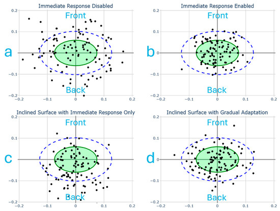
Figure 10.
CoM location samples during different experiments. (a) Forward walking on flat terrain without Immediate Response enabled. (b) Forward walking on flat terrain with Immediate Response enabled. (c) Walking on inclined surface with Immediate Response only. (d) Walking on an inclined surface with both Immediate Response and Gradual Adaptation enabled.
In the first experiment, the robot walked forward at a constant velocity of 0.1 m/s on a flat terrain while minor perturbations were applied from random directions. To apply these perturbations during walking, a 1 kg weight was hung from a wheeled frame that moved with the robot. As RoboMan II walked, we pulled the weight 1 m away from the robot’s CoM and released it to hit the CoM of the robot.
Figure 10a,b demonstrates the CoM locations during double support after the application of perturbation. Figure 10a demonstrates these locations without the Immediate Response and Gradual Adaptation control systems enabled. As can be seen, the majority (72%) of the CoMs are outside the stable zone.
In contrast, Figure 10b shows the CoM locations with the Immediate Response feedback enabled. Points are more concentrated within the center, indicating improved stability, with stability in the green zone increasing from 24% to 58%.
In the second experiment, Figure 10c,d, the robot walked on a path with increasing inclination (up to 10%) to evaluate its balance in the face of a changing terrain. Figure 10c shows the CoM locations with only the Immediate Response enabled. As the inclination increases, the CoM locations tend to go backward, indicating that the Immediate Response Loop alone cannot handle gradual changes effectively. Figure 10d shows the CoM locations with both Immediate Response and Gradual Adaptation enabled. CoMs are more centered, demonstrating the robot’s improved ability to maintain balance on uneven terrain, increasing from 38% in the stable region to 51%.
5. Discussion
We introduced RoboMan II, a lightweight adult-sized robot designed with enhanced inherent stability and balance control to facilitate the development of humanoid robots with complex functionality. The modified footplate and lightweight structure improve inherent stability, and the redesigned lower limb links allow RoboMan II to sit down, aiding in better recovery after falls and enabling object manipulation in future versions. The robot also features Dynamic Gait Frequency Adjustment, which adapts step frequency to optimize energy efficiency and maintain stability during various activities. The Immediate Response Loop for balance control provides rapid posture adjustments in response to sudden disturbances, utilizing IMU-based balance control and a Proportional-Derivative (PD) controller to ensure robust and fast stability. Additionally, the Gradual Adaptation Loop for long-term stability makes extended adjustments based on continuous sensor data analysis, maintaining stability on varying terrain.
Looking forward, RoboMan III aims to push the boundaries of humanoid robotics further. We are designing an adult-sized robot equipped with custom servo motors that offer increased speed and stability due to their enhanced mechanical and electronic design, providing higher speed and torque. More importantly, the modified gears in the homegrown gearbox prevent the disengagement of the gears after a fall. Moreover, we are refining our balance control methods to further enhance the robot’s stability, ensuring it can handle even more challenging environments and tasks. Through these advancements, RoboMan III will serve as a more capable platform for research and practical applications in humanoid robotics.
In parallel, other types of legged robots are being developed simultaneously. For example, the Mini Cheetah is a robust quadruped robot that uses custom back-drivable modular actuators [27]. These robots are progressing rapidly, as demonstrated in a study that introduced a motion optimization framework for hybrid wheeled-legged quadruped robots. This framework enables agile and fast navigation of challenging terrains using non-steerable wheels and dynamic jumps [28]. Although balance problems in four-legged robots are easier to resolve, humanoid robots remain highly relevant due to their potential to replace humans in perilous and tedious environments and their critical role in human–robot interactions (HRIs), especially in clinical settings.
Enhancing human–robot interactions is another key focus area. Research on soft humanoid robots emphasizes the integration of soft materials and hybrid soft actuators, advancing physical human–robot interactions [29]. Researchers are working on robotic exoskeletons and prostheses, which need to operate close to the human body using soft, lightweight, acoustically noiseless muscle-like actuators [30]. To develop these devices, some research groups have examined dielectric elastomer actuators (DEAs) as artificial muscles in rehabilitation robots [31]. In terms of rehabilitation, there is ongoing work to improve walking gait by reducing excessive ankle plantar flexion and knee extension, aligning joint motions with healthy individuals and decreasing the required ankle and hip power [32].
In terms of HRIs, researchers are working to make the interactions between robots and humans more intuitive. A study on multimodal human–robot interactions developed systems for speech recognition, dialog processing, and visual user perception [33]. Another crucial aspect of HRIs is the robot’s perception of its environment, such as having a sense of touch and object manipulation. Researchers are developing robotic hands capable of grasping various objects using different control methods, such as impedance control [34,35]. These advancements aim to enhance the robot’s ability to interact more naturally and effectively with its surroundings. Due to its modified mechanical structure, RoboMan II is capable of sitting, and RoboMan III can leverage haptic hands for object manipulation and enhanced interaction with the environment.
6. Conclusions
In conclusion, RoboMan II represents a significant advancement in humanoid robotics, featuring enhanced stability, dynamic gait adjustment, and improved balance control mechanisms. These enhancements make it an excellent platform for developing complex functionalities, such as object manipulation and vision processing. The innovations in RoboMan II, such as the Immediate Response Loop for rapid posture adjustments and the Gradual Adaptation Loop for long-term stability, have significantly improved its performance on varied terrains. Looking forward, RoboMan III will further push the boundaries of humanoid robotics with custom servo motors for increased speed and stability, refined balance control methods, and advanced mechanical designs to prevent gear disengagement after a fall. These developments, along with parallel advancements in soft robotics, exoskeletons, and human–robot interactions, underscore the potential for humanoid robots to replace humans in hazardous and tedious environments and to assist humans in activities of daily living and in healthcare facilities.
Author Contributions
Conceptualization, V.M. and M.H.; methodology, V.M., M.H. and F.J.; software, M.H. and F.J.; validation, V.M., M.H. and A.B.; formal analysis, V.M. and M.H.; investigation, V.M. and A.B.; resources, A.B.; data curation, V.M. and M.H.; writing—original draft preparation, V.M., M.H. and F.J.; writing—review and editing, A.B.; visualization, V.M.; supervision, A.B.; project administration, V.M. and M.H.; funding acquisition, A.B. All authors have read and agreed to the published version of the manuscript.
Funding
National Institutes of Health: P20GM109090, P20GM152301.
Data Availability Statement
The data will be available on GitHub.
Acknowledgments
We gratefully acknowledge the late Esfandiar Bamdad for his invaluable help and advice in developing RoboMan I and RoboMan II. His contributions were essential to our progress, and his impact will never be forgotten.
Conflicts of Interest
Author Mojtaba Hosseini was employed by Energy Robotics GmbH. The remaining authors declare that the research was conducted without any commercial or financial relationships that could be construed as a potential conflict of interest.
References
- Hirose, M.; Ogawa, K. Honda humanoid robots development. Phil. Trans. R. Soc. A 2007, 365, 11–19. [Google Scholar] [CrossRef] [PubMed]
- Kaneko, K.; Harada, K.; Kanehiro, F.; Miyamori, G.; Akachi, K. Humanoid robot HRP-3. In Proceedings of the 2008 IEEE/RSJ International Conference on Intelligent Robots and Systems, Nice, France, 22–26 September 2008; IEEE: Piscataway, NJ, USA, 2018; pp. 2471–2478. [Google Scholar] [CrossRef]
- Diftler, M.A.; Mehling, J.S.; Abdallah, M.E.; Radford, N.A.; Bridgwater, L.B.; Sanders, A.M.; Askew, R.S.; Linn, D.M.; Yamokoski, J.D.; Permenter, F.A.; et al. Robonaut 2—The first humanoid robot in space. In Proceedings of the 2011 IEEE International Conference on Robotics and Automation, Shanghai, China, 9–13 May 2011; IEEE: Piscataway, NJ, USA, 2011; pp. 2178–2183. [Google Scholar] [CrossRef]
- Nelson, G.; Saunders, A.; Neville, N.; Swilling, B.; Bondaryk, J.; Billings, D.; Lee, C.; Playter, R.; Raibert, M. PETMAN: A Humanoid Robot for Testing Chemical Protective Clothing. JRSJ 2012, 30, 372–377. [Google Scholar] [CrossRef]
- Kuindersma, S.; Deits, R.; Fallon, M.; Valenzuela, A.; Dai, H.; Permenter, F.; Koolen, T.; Marion, P.; Tedrake, R. Optimization-based locomotion planning, estimation, and control design for the atlas humanoid robot. Auton. Robot. 2016, 40, 429–455. [Google Scholar] [CrossRef]
- Griffin, R.J.; Wiedebach, G.; Bertrand, S.; Leonessa, A.; Pratt, J. Walking stabilization using step timing and location adjustment on the humanoid robot, Atlas. In Proceedings of the 2017 IEEE/RSJ International Conference on Intelligent Robots and Systems (IROS), Vancouver, BC, Canada, 24–28 September 2017; pp. 667–673. [Google Scholar] [CrossRef]
- Friedmann, M.; Kiener, J.; Kratz, R.; Petters, S.; Stelzer, M.; Thomas, D. Team Description Paper: Darmstadt Dribblers & Hajime Team (KidSize) and Darmstadt Dribblers (TeenSize). Rob. Humanoid Leag. 2006. [Google Scholar]
- Farazi, H.; Allgeuer, P.; Ficht, G.; Brandenburger, A.; Pavlichenko, D.; Schreiber, M.; Behnke, S. RoboCup 2016 Humanoid TeenSize Winner NimbRo: Robust Visual Perception and Soccer Behaviors. In RoboCup 2016: Robot World Cup XX; Behnke, S., Sheh, R., Sarıel, S., Lee, D.D., Eds.; Lecture Notes in Computer Science; Springer International Publishing: Cham, Switzerland, 2017; Volume 9776, pp. 478–490. [Google Scholar] [CrossRef]
- Knabe, C.; Hopkins, M.; Hong, D.W. Team CHARLI: RoboCup 2012 Humanoid AdultSize League Winner. In Proceedings of the RoboCup 2012: Robot Soccer World Cup XVI, Mexico City, Mexico, 18–24 June 2012; Chen, X., Stone, P., Sucar, L.E., Van Der Zant, T., Eds.; Lecture Notes in Computer Science. Springer: Berlin/Heidelberg, Germany, 2013; Volume 7500, pp. 59–64. [Google Scholar] [CrossRef]
- Kasaei, S.M.; Lau, N.; Pereira, A.; Shahri, E. A reliable model-based walking engine with push recovery capability. In Proceedings of the 2017 IEEE International Conference on Autonomous Robot Systems and Competitions (ICARSC), Coimbra, Portugal, 26–28 April 2017; IEEE: Piscataway, NJ, USA, 2018; pp. 122–127. [Google Scholar] [CrossRef]
- Kasaei, M.; Lau, N.; Pereira, A. An optimal closed-loop framework to develop stable walking for humanoid robot. In Proceedings of the 2018 IEEE International Conference on Autonomous Robot Systems and Competitions (ICARSC), Torres Vedras, Portugal, 25–27 April 2018; IEEE: Piscataway, NJ, USA, 2018; pp. 30–35. [Google Scholar] [CrossRef]
- Kuo, C.-H.; Chia, P.-C.; Tsai, T.-C.; Kuo, Y.-C.; Wu, M.-H. Team Description Paper: HuroEvolutionAD Humanoid Robot for RoboCup 2011 Humanoid League. Available online: https://humanoid.robocup.org/qualification/2011/d2bf1b0eae16d5b76ca8a12d7c3c5c0f0c6a75a8/HuroEvolution_AD_HumanoidAdultSize_2011_TDP.pdf (accessed on 25 September 2024).
- Mohammadi, V.; Hosseini, M.; Jafari, F.; Farazi, H.; Bamdad, D.E. Baset Adult-Size 2015 Team Description Paper. Available online: https://humanoid.robocup.org/qualification/2015/4ab6ed9739b72c119972ac674c6ee9adfa01a65c/Baset_Adult_Size_Humanoid_AdultSize_2015_TDP.pdf (accessed on 25 September 2024).
- Yi, S.J.; McGill, S.; Jeong, H.; Huh, J.; Missura, M.; Yi, H.; Ahn, M.S.; Cho, S.; Liu, K.; Hong, D.; et al. RoboCup 2015 Humanoid AdultSize League Winner. In Proceedings of the RoboCup 2015: Robot World Cup XIX, Hefei, China, 23 July 2015; Almeida, L., Ji, J., Steinbauer, G., Luke, S., Eds.; Lecture Notes in Computer Science. Springer International Publishing: Cham, Switzerland, 2015; Volume 9513, pp. 132–143. [Google Scholar] [CrossRef]
- Dorer, K.; Hochberg, U.; Wulker, M. The Sweaty 2019 RoboCup Humanoid Adult Size Team Description. 2019. Available online: https://archive.robocup.info/Soccer/Humanoid/AdultSize/TDPs/RoboCup/2019/Sweaty_HL-Adult_RC2019_TDP.pdf (accessed on 25 September 2024).
- Han, J.; Park, C.; Kim, Y.; Yoo, D.; Min, I.; Yoon, D.; Eum, Y. HERoEHS, Team Description Paper. 2019. Available online: https://submission.robocuphumanoid.com/uploads//HERoEHS-tdp-5c4ea558805c8.pdf (accessed on 25 September 2024).
- Ahn, M.S.; Zhu, T.; Hong, D. RoMeLa Team Description Paper for RoboCup 2019 Humanoid League. 2019. Available online: https://archive.robocup.info/Soccer/Humanoid/AdultSize/TDPs/RoboCup/2019/RoMeLa_HL-Adult_RC2019_TDP.pdf (accessed on 25 September 2024).
- Pavlichenko, D.; Ficht, G.; Amini, A.; Hosseini, M.; Memmesheimer, R.; Villar-Corrales, A.; Schulz, S.M.; Missura, M.; Bennewitz, M.; Behnke, S. RoboCup 2022 AdultSize Winner NimbRo: Upgraded Perception, Capture Steps Gait and Phase-Based In-Walk Kicks. In RoboCup 2022; Eguchi, A., Lau, N., Paetzel-Prüsmann, M., Wanichanon, T., Eds.; Lecture Notes in Computer Science; Springer International Publishing: Cham, Switzerland, 2023; Volume 13561, pp. 240–252. [Google Scholar] [CrossRef]
- Han, J.-K.; Ha, I.-Y.; Kim, B.-S. Educational Robotic Construction Kit: Bioloid. In Proceedings of the 17th World Congress the International Federation of Automatic Control, Seoul, Republic of Korea, 6–11 July 2008. [Google Scholar]
- Ha, I.; Tamura, Y.; Asama, H.; Han, J.; Hong, D.W. Development of open humanoid platform DARwIn-OP. In Proceedings of the SICE Annual Conference 2011, Tokyo, Japan, 13–18 September 2011. [Google Scholar]
- Available online: https://www.robotlab.com/hubfs/PDFs/RobotLAB/RobotLAB_Introduction_to_NAO_Textbook_TOC.pdf?srsltid=AfmBOoqcHiACsFIjA4AhYuX5W4HG4GvflesESCx2GzoBsmYGE3bXv9ZB (accessed on 25 September 2024).
- Hosseini, M.; Mohammadi, V.; Jafari, F.; Bamdad, E. RoboCup 2016 Best Humanoid Award Winner Team Baset Adult-Size. In Proceedings of the RoboCup 2016: Robot World Cup XX, Leipzig, Germany, 30 June–4 July 2016; Behnke, S., Sheh, R., Sarıel, S., Lee, D.D., Eds.; Lecture Notes in Computer Science. Springer International Publishing: Cham, Switzerland, 2017; Volume 9776, pp. 467–477. [Google Scholar] [CrossRef]
- BeagleBone Black. Available online: https://www.beagleboard.org/boards/beaglebone-black (accessed on 1 June 2016).
- MAX13488E. Available online: https://www.analog.com/en/products/max13488e.html (accessed on 25 September 2024).
- Han, J. Bipedal Walking for a Full-sized Humanoid Robot Utilizing Sinusoidal Feet Trajectories and Its Energy Consumption. Ph.D. Thesis, Hanyang University, Seoul, Republic of Korea, 2012. [Google Scholar]
- Missura, M.; Bennewitz, M.; Behnke, S. Capture Steps: Robust Walking for Humanoid Robots. Int. J. Human. Robot. 2019, 16, 1950032. [Google Scholar] [CrossRef]
- Katz, B.; Carlo, J.D.; Kim, S. Mini Cheetah: A Platform for Pushing the Limits of Dynamic Quadruped Control. In Proceedings of the 2019 International Conference on Robotics and Automation (ICRA), Montreal, QC, Canada, 20–24 May 2019; IEEE: Piscataway, NJ, USA, 2019; pp. 6295–6301. [Google Scholar] [CrossRef]
- Hosseini, M.; Rodriguez, D.; Behnke, S. Dynamic Hybrid Locomotion and Jumping for Wheeled-Legged Quadrupeds. In Proceedings of the 2023 IEEE/RSJ International Conference on Intelligent Robots and Systems (IROS), Detroit, MI, USA, 1–5 October 2023; IEEE: Piscataway, NJ, USA, 2023; pp. 793–799. [Google Scholar] [CrossRef]
- Niiyama, R. Soft Actuation and Compliant Mechanisms in Humanoid Robots. Curr. Robot. Rep. 2022, 3, 111–117. [Google Scholar] [CrossRef]
- Mohammadi, V.; Tajdani, M.; Masaei, M.; Ghalehney, S.M.; Lee, S.C.K.; Behboodi, A. DE-AFO: A Robotic Ankle Foot Orthosis for Children with Cerebral Palsy Powered by Dielectric Elastomer Artificial Muscle. Sensors 2024, 24, 3787. [Google Scholar] [CrossRef] [PubMed]
- Behboodi, A.; DeSantis, C.; Lubsen, J.; Lee, S.C.K. A Mechanized Pediatric Elbow Joint Powered by a De-Based Artificial Skeletal Muscle. In Proceedings of the 2020 42nd Annual International Conference of the IEEE Engineering in Medicine & Biology Society (EMBC), Montreal, QC, Canada, 20–24 July 2020; IEEE: Piscataway, NJ, USA, 2020; pp. 4930–4935. [Google Scholar] [CrossRef]
- Fallahtafti, F.; Samson, K.; Salamifar, Z.; Johanning, J.; Pipinos, I.; Myers, S.A. Enhancing walking performance in patients with peripheral arterial disease: An intervention with ankle-foot orthosis. Int. J. Cardiol. 2024, 407, 131992. [Google Scholar] [CrossRef] [PubMed]
- Stiefelhagen, R.; Ekenel, H.K.; Fugen, C.; Gieselmann, P.; Holzapfel, H.; Kraft, F. Enabling Multimodal Human–Robot Interaction for the Karlsruhe Humanoid Robot. IEEE Trans. Robot. 2007, 23, 840–851. [Google Scholar] [CrossRef]
- Mohammadi, V.; Shahbad, R.; Hosseini, M.; Gholampour, M.H.; Shiry Ghidary, S.; Najafi, F.; Behboodi, A. Development of a Two-Finger Haptic Robotic Hand with Novel Stiffness Detection and Impedance Control. Sensors 2024, 24, 2585. [Google Scholar] [CrossRef] [PubMed]
- Romano, J.M.; Hsiao, K.; Niemeyer, G.; Chitta, S.; Kuchenbecker, K.J. Human-Inspired Robotic Grasp Control With Tactile Sensing. IEEE Trans. Robot. 2011, 27, 1067–1079. [Google Scholar] [CrossRef]
Disclaimer/Publisher’s Note: The statements, opinions and data contained in all publications are solely those of the individual author(s) and contributor(s) and not of MDPI and/or the editor(s). MDPI and/or the editor(s) disclaim responsibility for any injury to people or property resulting from any ideas, methods, instructions or products referred to in the content. |
© 2024 by the authors. Licensee MDPI, Basel, Switzerland. This article is an open access article distributed under the terms and conditions of the Creative Commons Attribution (CC BY) license (https://creativecommons.org/licenses/by/4.0/).