Article

Increasing Horizontal Controlled Force Delivery Capabilities of Aerial Manipulators by Leveraging the Environment

by
Santos Miguel Orozco Soto
1,* and
Vincenzo Lippiello
2
1
Science and Technology College, Autonomous University of Mexico City, Mexico City 06720, Mexico
2
Department of Electrical Engineering and Information Technology, University of Naples Federico II, 80125 Naples, Italy
*
Author to whom correspondence should be addressed.
Robotics 2024, 13(10), 147; https://doi.org/10.3390/robotics13100147
Submission received: 31 July 2024 / Revised: 20 September 2024 / Accepted: 27 September 2024 / Published: 29 September 2024
(This article belongs to the Section Aerospace Robotics and Autonomous Systems)

Abstract

:
Delivering large horizontal controlled forces for long periods with aerial manipulators is not an easy task to accomplish; several factors including disturbances, reaction forces from the on-board arm or actuator’s limitations might diminish their horizontal force delivery capabilities. Aiming to mitigate these drawbacks, this paper presents a comprehensive study of the force delivery capabilities of aerial manipulators leveraging the environment. The methodology to evaluate the aforementioned capabilities is the Generalized-Jacobian-based force ellipsoid, which was applied to different types of both free-flying and attached-to-the-environment aerial manipulators. In addition, large controlled force delivery experiments with the mentioned manipulators were conducted on physics-engine-based robotics simulation software. The obtained results categorically demonstrate that aerial manipulators leveraging the environment are capable of delivering larger forces than their free-flying counterparts, which has not been proved in the literature so far in the field of aerial robotics.

1. Introduction

Aerial manipulators have been recently employed in tasks demanding the application of sustained forces perpendicular to gravity (often referred to as horizontal force), such as maintenance and inspection of pipelines or electrical facilities, among other similar industrial applications [1]. Sustained horizontal force delivery is not easy to accomplish as a consequence of several factors, for instance, the aerial manipulator uses most of its power to keep hovering, so it remains less energy to exert a horizontal wrench. Another shortcoming is the detriment of the precision of a task that occurs when disturbances affect the flight of the unmanned aerial vehicle (UAV) [2]. A general hypothesis assumed by the research community states that, if the aerial manipulator leverages the environment, its force delivery capacity would increase, overcoming the traditional free-flying force delivery [2]. Such reasoning takes inspiration from the fact that humans exploit contacts to perform tasks more comfortably and efficiently, reducing the required muscular effort as well [3]. Even though this intuition might be obvious, there are neither proofs nor data reported in the literature supporting this statement up to the best authors’ knowledge, at least in the case of aerial manipulators. Employing the wrong force analysis tool might lead to unexpected opposite conclusions.
Motivated by the above reasoning, this paper presents a comprehensive study of the horizontal force delivery capabilities of aerial manipulators leveraging the environment. The analysis tool employed is the force ellipsoid obtained through the Generalized Jacobian of aerial manipulators [4,5], which was computed for several configurations of free-flying and attached-to-the-environment types of manipulators. Such an analysis was also contrasted against the well-known Kinematic Jacobian from the literature (or Normal Jacobian as it is commonly called [5]). In this study, three types of aerial manipulators were compared: (i) a free-flying UAV with a three-degree-of-freedom (DOF) robotic arm on board; (ii) a UAV attached to the environment through a passive joint with the 3-DOF robotic arm on board and (iii) a UAV attached to the environment using two passive joints with a 3-DOF robot on board as well.
In addition, controlled force delivery experiments were carried out to prove the improved force delivery capabilities, which were performed using a physics-engine-based simulation environment that provides a more realistic behavior than traditional numerical simulation approaches.
The contributions of this research are listed below:
1.
A comprehensive analysis was performed to determine a consistent advantage, in large horizontal force delivery, of aerial manipulators leveraging the environment over those flying freely. Such an assertion has not been proved yet in the literature, neither theoretically nor with data.
2.
To the authors’ knowledge, this is the first time that force manipulability ellipsoids are computed using the Generalized Jacobian originally used for space robotics and first proposed by Umetani [6] (this Generalized Jacobian must not be confused with other “Generalized Jacobians” proposed in [7,8,9] or [10]), which may become an overriding tool for aerial manipulators analysis and design.
3.
This work presents a novel approach to deliver large horizontal controlled forces for long periods using attached aerial manipulators, which has not been reported in the literature so far.
The rest of the paper is organized as follows. Section 2 presents the state of the art related to this work. Section 3 covers the mathematical tools and formulates the problem of sustained horizontal force delivery. The main results regarding force delivery capabilities analysis are presented in Section 4. Section 5 presents the controlled force experiments performed on the physics-engine-based simulator. Section 6 concludes the paper.

2. Related Work

Attaching (perching, holding, grabbing, fastening, etc.) an aerial manipulator to the environment is an interesting functionality for two main reasons: (i) it allows robots to conserve energy and/or recharge their batteries [11], or permits to assign the whole energy to the on board robotic arm’s work by stopping the propellers [12]; (ii) leveraging the environment is helpful to mitigate disturbances affecting hovering and it apparently improves the force exertion capacity perpendicular to gravity [2,12], which is the focus of this research.
It is worth remarking that leveraging the environment to generate large Cartesian forces or to improve the precision of the executed task is not peculiar to the aerial robotics field. Indeed, this technique is frequently used in multilimbed and humanoid robots [3,13,14,15]. According to the literature, there are two ways of delivering large forces with aerial manipulators: utilizing vectored thrust to decouple its attitude from force tasks or leveraging environmental forces [16].
There are several important results reported in the literature regarding free-flying manipulators delivering large or sustained forces. One of the most remarkable earliest results is presented in [17], where the authors used a tri-tiltrotor to push obstacles; even though the robot is not reported as an aerial manipulator, its architecture falls in the free-flying-with-stick category. The contact force was neither measured nor observed, but the estimated horizontal force delivered in an open loop by the tilting rotors was about 18 [N] for 30 [s]. Another significant contribution is reported in [18], this work reports a noteworthy sustained uncontrolled contact of 14 [N] during 240 [s] with an aerial manipulator. In addition, ref. [19] presents a stick-type aerial manipulator achieving a delivered uncontrolled force of up to 60 [N] for 1.5 [s]. The aforementioned outstanding works stated the basis of aerial robots interacting with the environment; nonetheless, more recent applications require that such an interaction must be performed in a controlled way, namely to measure or estimate the external wrench to precisely control its magnitude [20]. Among these applications, power lines maintenance [1] and non-destructive tests for facilities inspection stand out as the most recent industrial applications [21]. So, regarding controlled force delivery, the authors in [20] employed an aerial manipulator with tilting propellers endowed with a force sensor at the tip of the arm in order to deliver horizontal force to a rigid environment, achieving 2.2 [N] for 80 [s] by means of an implicit-position force control; although such results were obtained through physics-engine-based simulations, the robot’s behavior is practically the same as the real one’s, as it has been demonstrated in other experimental works [20,21,22,23]; hence, the reported achievements are trustworthy. Nonetheless, some of the aforementioned applications demand the delivery of larger controlled sustained forces, so trying to fulfill such a requirement, the authors in [24] employed a similar robotic platform but this time making use of a hybrid position/force control, delivering up to 8 [N] for 120 [s]. Up to this point, it might seem that larger forces can be attained in an open loop, but the remarkable differences between whether or not closing the force loop rely on the duration of the desired delivered force and the stability of the UAV while it is in contact with the environment.
On the other hand, fascinating results of force application with aerial manipulators leveraging the environment have been reported as well. In [25], an aerial manipulator equipped with a pneumatic end-effector was implemented to generate an approximately 40 [Nm] torque to twist a door knob; the aerial manipulator was attached to the door using suction cups. Another interesting research was reported in [26]; the authors developed a micro air vehicle (MAV) endowed with microspines to firmly adhere to the ground and then pull heavy objects with a winch. Despite such research not regarding force delivery, it provides useful insights about the importance of leveraging the environment. Nevertheless, as it was mentioned for the case of free-flying aerial manipulators, there are some applications that require large controlled force delivery, for instance, to protect the force application surface or to guarantee the correct operation of a determined tool. Table 1 summarizes the aforementioned state-of-the-art results. Thus, considering the literature so far, there is no evidence of delivering controlled forces to the environment with attached aerial manipulators.

3. Problem Formulation and Methodology

3.1. Problem Formulation

Taking into account the related work so far, it can be concluded that delivering large horizontal controlled forces for long periods with aerial manipulators is not an easy task to accomplish. The reasons behind this are the energy spent by the UAV, its actuator’s limitations and the disturbances caused by the forces interchange between the aerial manipulator and the environment. Although the attachment of the UAV to the environment has been proposed by some authors to overcome such drawbacks, successful horizontal controlled force delivery with attached aerial manipulators has not been reported so far to the best of the author’s knowledge. Thus, the main target of this work is to prove that attaching the aerial manipulator to the environment is more beneficial to delivering larger horizontal controlled forces for long periods than flying freely. In this context, the research problem is to demonstrate such an affirmation both theoretically and with experiments, so the analysis tools employed for this purpose are presented below.

3.2. Force Ellipsoids with Actuators Weighting

It is well known that robot manipulators’ wrench delivery capability depends on their design, their joint configuration and their actuator limits [27]; the literature is rich with techniques to evaluate such a capability, and most of them are based on the so-called force ellipsoid with actuator limits given by [28]
f T J J + J J T f 1 ,
where f R m is the end-effector external wrench applied in a m-dimensional space and J = J W R m × n is a scaled Jacobian compound by the Jacobian matrix J R m × n and the weighting matrix W R n × n . The former is a forward kinematics function of the n-DOF manipulator, while the latter represents the actuator limits and can be computed by
W = diag 1 τ 1 M A X , 1 τ 2 M A X , , 1 τ n M A X ,
where τ i M A X is a scalar denoting the maximum torque that the i-th actuator is capable to supply [28]. Moreover, ( · ) + stands for the pseudo-inverse operator. So, in order to obtain the principal axes of the ellipsoid (1) and its volume, the singular value decomposition [29]
J T = U Σ V T ,
must be computed, yielding U R n × n , V R m × m and
Σ R n × m diag ( σ 1 , σ 2 , , σ n ) 0 n ,
with 0 n denoting a zero vector of dimension n and σ 1 , , σ n R are the singular values of J . Thus, the principal axes of the force ellipsoid are σ 1 u 1 , σ 2 u 2 , σ n , u n , and its volume can be obtained through
υ f = 2 n π n / 2 n 2 1 ! i n σ i ,
with i = 1 , , n singular values.

3.3. Generalized Jacobian of Aerial Manipulators

The Generalized Jacobian is a mathematical tool firstly derived to analyze and control space robotic arms mounted on satellites, according to its inertial and kinematic properties [4,30]. Such a tool is also useful to analyze how the motion of the mounted arm on an aerial manipulator affects the motion of the UAV carrying it since the kinematics of the space robot and the aerial manipulator hovering are the same [5]. The derivation of the Generalized Jacobian for aerial manipulators is described below. It is worth mentioning that all the following theory incorporates the results of [4,5,30], so several redundant citations will be avoided in the rest of this subsection.

3.3.1. Kinematic Jacobian of Aerial Manipulators

Consider Figure 1, where an aerial manipulator with its kinematic parameters is depicted. The position of the end-effector of a n —DOF manipulator mounted on a UAV with respect to the inertial frame is given by
p e R 3 r 0 + b 0 + i = 1 n l i ,
where r 0 R 3 is the position of the aerial manipulator’s UAV with respect to the inertial frame O W , b 0 R 3 is the position vector of the first link joint and l i R 3 is the position vector of the end of the i-th link. So the linear velocity of the end-effector as a function of the UAV and joint linear velocities is obtained through
v e R 3 p ˙ e = v 0 + ω 0 × p e r 0 + i = 1 n k i × ( p e p j i ) q ˙ i ,
where v 0 R 3 and ω 0 R 3 are the linear and angular velocities of the aerial manipulator’s UAV, k i = [ 0 0 1 ] T denotes a rotational axis about the i-th joint of the mounted arm, p j i is the position vector of the i-th joint and q ˙ i R is the angular velocity of the i-th joint of the aforementioned arm. On the other hand, the angular velocity of the end-effector as a function of the UAV and joint angular velocities can be obtained with
ω e R 3 ω 0 + i = 1 n k i q ˙ i .
Lumping both linear and angular velocities of the end-effector as v R 6 v e T ω e T T , the following relationship holds
v = J 0 v 0 ω 0 + J m q ˙ ,
where
J 0 R 6 × 6 I 3 × 3 p ˜ 0 e 0 3 × 3 I 3 × 3
represents the Jacobian matrix of the UAV with p ˜ 0 e R 3 × 3 denoting the skew-symmetric operator of p e r 0 and
J m R 6 × n k 1 × ( p e p 1 ) k 2 × ( p e p 2 ) k n × ( p e p n ) k 1 k 2 k n
is the Jacobian of the on-board manipulator, which is the same as the Jacobian for the ground fixed manipulators [31,32]. For convenience, (9) can be split for each link as
J T i R 3 × n k 1 × ( r i p 1 ) k 2 × ( r i p 2 ) k i × ( r i p i ) 0 0
J R i R 3 × n k 1 k 2 k i 0 0 ,                                                                                                                
with i = 1 , 2 , . . . , n .

3.3.2. Generalized Jacobian

The CoG of the UAV r g R 3 with respect to the inertial frame O W is given by
r g i = 0 n m i = i = 0 n m i r i ,
where r i R 3 is the CoG of each aerial manipulator component. Taking the momentum conservation law into account, the translational momentum with respect to the inertial frame O W is constant, namely
m T R 3 i = 0 n m i r ˙ i ,
where m i denotes the scalar mass of the i-component. The same holds for the angular momentum of the aerial manipulator with respect to the inertial frame O W as follows
m A R 3 i = 0 n I i ω i + r i × m i r ˙ i ,
where I i R 3 × 3 and ω i R 3 are the inertia tensor and the angular velocity vector of the i-th component, respectively. Then, rearranging the inertia variables as
I ω R 3 × 3 i = 1 n I i m i r ˜ i r ˜ 0 i ,
I q R 3 × 3 i = 1 n I i J R i + m i r ˜ i J T i ,
with r ˜ i , r ˜ 0 i R 3 × 3 denoting the skew-symmetric operator of r i and r i r 0 accordingly, the total momentum of the aerial manipulator can be represented using
m A m T = w I 3 × 3 w r ˜ 0 g T w r ˜ g I ω v 0 ω 0 + J T ω I q q ˙ ,
where w = i = 0 n m i is the total scalar weight of the aerial manipulator system, J T ω R 3 × n i = 1 n m i J T i and r ˜ g , r ˜ 0 g R 3 × 3 represent the skew-symmetric operator of r g and r g r 0 , respectively. Now taking into account the momentum conservation law and solving for v 0 and ω 0 with the total moment as zero it yields
v 0 = J T ω w + r ˜ 0 g I u 1 I a q ˙ ,
ω 0 = I u 1 I a q ˙ ,
where I u R 3 × 3 I ω + w r ˜ g r ˜ 0 g is the total inertia of the UAV and I a R 3 × 3 I q r ˜ g J T ω is the total inertia of the mounted arm. Substituting (20) and (21) in (9) it gives
v = J ( ) J 0 J T ω w 0 3 × n J 0 r ˜ 0 g I 3 × 3 I u 1 I a J ˜ R 6 × n q ˙ ,
where J ˜ is the Generalized Jacobian of the aerial manipulator.

4. Force Delivery Capabilities of Aerial Manipulators

4.1. Aerial Manipulators Cases Study

In order to solve the formulated research problem, three different aerial manipulator setups are studied. The first case study is a free-flying aerial manipulator, which is shown in Figure 2a); such an aerial robot is composed of an actively tilting quadrotor with a 3-DOF manipulator on board. Moreover, it delivers horizontal force along its x e axis with the arm completely extended and pushing towards the environment, so its tilting propellers are exploited to perform horizontal motion with the UAV’s attitude angles completely set to zero. The second case study is the same aforementioned aerial manipulator but this time it is attached to the environment through a rigid link with a passive joint as it can be appreciated in Figure 2b), so that the robot motion is constrained only to the x-z plane to deliver force on the environment towards the x e axis of the end-effector, exploiting both the UAV motion and the on-board arm for this purpose. The final setup is a compound of the same aerial manipulator but this time it is attached to the environment by means of a rigid link provided with two passive joints as depicted in Figure 2c); again, the robot motion is constrained only to the x-z plane.
The motivation behind the addition of passive joints is twofold: firstly, the UAV turns into an additional controllable link whose actuator capabilities can be exploited to perform high torques. Secondly, such passive joints provide the full system with compliance, so that in case of eventual disturbances or if the aerial manipulator is too heavy, a completely constrained system would break the link, so the attachment is merely for leveraging rather than for supporting the whole robot weight.
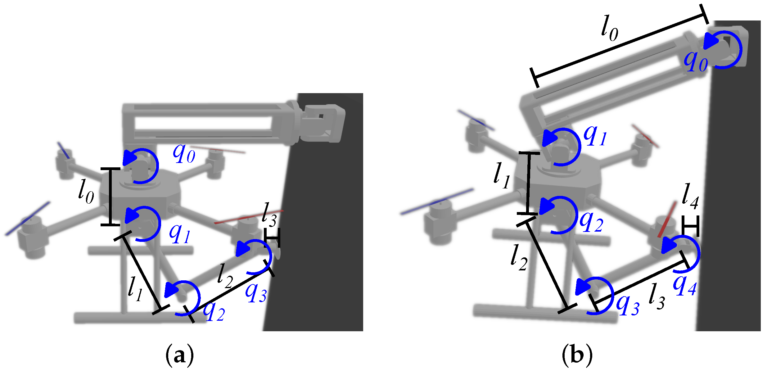
The kinematic parameters of the aerial manipulators used in this study are presented in Figure 3 and their corresponding values are listed in Table 2. Notice that the free-flying arm parameters are the same as those of the attached with one passive joint except for l 0 , since the former is not attached.

4.2. Kinematic-Jacobian-Based Force Delivery Capabilities

Let us consider the following assumptions:
A1.
The six-dimensional aerial manipulator motion will be neglected and only a x-z plane will be considered for two reasons: On the one hand, the interest of this study is the horizontal force delivery along x e axis on a single point of the environment. On the other hand, the attachment of the UAV to the environment constrains its motion to the x-z plane only.
A2.
For the case of the free-flying manipulator, the UAV is rigidly controlled in attitude, but it is capable of performing horizontal motions thanks to its actively tilting propellers.
A3.
Regarding the attached aerial manipulators, the maximum torque is supplied by the UAV link actuators. The torque capabilities of all the on-board arm actuators are the same.
Consider the velocities relationship (9) and the kinematic parameters shown in Figure 1; taking into account the assumptions above, the Kinematic Jacobians of the aerial manipulators are
J F F = 1 0 l 1 s 1 l 2 s 12 l 3 s 123 0 1 l 1 c 1 l 2 c 12 l 3 c 123 ,
J A 1 = l 0 s 0 l 1 s 01 l 2 s 012 l 3 s 0123 l 0 c 0 l 1 c 01 l 2 c 012 l 3 c 0123 and
J A 2 = l 0 s 0 l 1 s 01 l 2 s 012 l 3 s 0123 l 4 s 01234 l 0 c 0 l 1 c 01 l 2 c 012 l 3 c 0123 l 4 c 01234 ,
with s 0 n denoting sin i = 0 n q i and c 0 n representing cos i = 0 n q i , as is commonly used in the literature. The subindices indicate F F for free-flying, A 1 for attached with one passive joint and A 2 for attached with two passive joints. This two-dimensional plane representation is valid and frequently used in the literature as well [32]; hence, the joint-to-end-effector velocities mappings are
v F F R 2 J F F x ˙ e z ˙ e q 1 q 2 q 3 q ˙ F F T ,
v A 1 R 2 J A 1 q 0 q 1 q 2 q 3 q ˙ A 1 T and
v A 2 R 2 J A 2 q 0 q 1 q 2 q 3 q 4 q ˙ A 2 T .
In order to determine the horizontal force delivery capabilities of each aerial manipulator type, the force ellipsoids volumes were computed by employing (3) for (23), (24) and (25). The force application scenario is the same for all the aerial manipulator setups; namely, the force application target point is set to x W = 0 [m] and a random point within the range 1.6 [m] z W 2 [m] for the free-flying setups and 1.4 [m] z W 1.8 [m] for the case of attached manipulators since they are attached at z W = 2 [m]. Thus, the corresponding inverse kinematics of each setup was computed in order to achieve such a given target point. For the case of the free-flying aerial manipulator, two cases were considered: in one hand, the force ellipsoid was computed considering the on-board arm completely extended as a rigid stick. On the other hand, the arm is movable. The force ellipsoids axes, inverse kinematics and plots were obtained numerically using the NumPy (https://numpy.org/, accessed on 25 September 2024) library of Python 3.7.
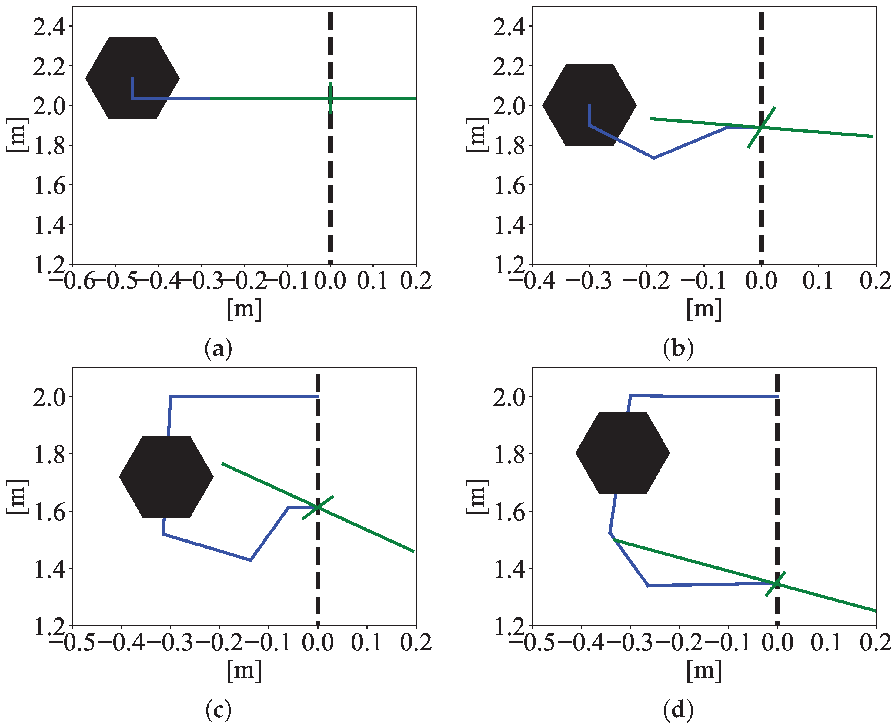
Figure 4 shows the force ellipsoids of each setup obtained for a random point within the aforementioned ranges of z W , where it can be appreciated that the free-flying UAV with movable arm setup has the largest force ellipsoid followed by the free-flying with stick, whereas the smallest force ellipsoid corresponds to the aerial manipulator attached with a single passive joint. These results derived from a purely kinematic analysis may lead to the wrong conclusion that a free-flying device is capable of delivering larger force than an attached one for the following reasons: first, the actuator’s capabilities are not considered; hence, it is worth remembering that the free-flying setups spend most of their actuator’s energy to keep the hovering by compensating for the weight of the UAV. Second, the reaction forces caused by the arms motion disturb significantly the UAV [33]; consequently, it is reasonable to expect a significant disturbance incoming from the arm pushing against a rigid environment.
Attempting to achieve more realistic results, an additional analysis considering the actuator’s capabilities was conducted. Thus, the actuator’s weighting matrices for each setup are
W F F = diag 2 , 2 / w F F , 1 / 0.25 , 1 / 0.25 , 1 / 0.25 ,
W A 1 = diag 1 , 1 / 0.25 , 1 / 0.25 , 1 / 0.25 and
W A 2 = diag 0 , 1 , 1 / 0.25 , 1 / 0.25 , 1 / 0.25 ,
where w F F is the weight of the UAV, compound by the gravity and a 10 [kg] mass. The value of 2 was determined because it is considered that the UAV’s actively tilting propellers are maximally set to 45 [°] to perform horizontal motions without changing their attitude and so that the actuators are still capable to maintain the hovering while exploiting the maximum possible horizontal thrust. In addition, it is considered that the maximum torque is supplied by the UAV link, and the arm’s actuators are capable of supplying up to 25% of such a torque. Finally, the first entry of W A 2 is considered to be zero since it corresponds to the passive joint.
Figure 5 shows the force ellipsoids axes of each setup including the actuator’s weighting matrix. Different from those results obtained only with the Kinematic Jacobian, now the aerial manipulator attached with two passive joints has the largest force ellipsoid qualitatively. It is worth noting that the free-flying setups have significantly larger horizontal axes than their vertical counterpart, which seems reasonable as a consequence of the actuator’s limitation for vertical force delivery. Although these results provide more realistic insights about force capabilities, the reaction forces that might disturb the free-flying UAV are still not considered, and it may seem that it is not worth attaching the aerial manipulator so far, provided that no significant difference between the force ellipsoids is visible, at least qualitatively. Therefore, the force delivery analysis tools used up to this point are ostensibly insufficient to establish a categorical statement about whether or not leveraging the environment to increase horizontal force delivery capabilities.

4.3. Main Result: Increasing Force Delivery Capabilities by Leveraging the Environment

In order to establish a meaningful analysis tool that would provide an unequivocal understanding of the force delivery capabilities of aerial manipulators, the following results based on the Generalized Jacobian are presented.
Proposition 1.
Consider the Generalized Jacobian of aerial manipulators (22). If the UAV is controlled with a fixed attitude so that the angular momentum conservation law is neglected, then
J ˜ J ˜ T J ( ) J 0 J T ω w 0 3 × n ,
with J ˜ T denoting a reduced version of the Generalized Jacobian that only considers the translational motion of the UAV; hereafter, J ˜ T is called the reduced Generalized Jacobian.
Proof. 
The attitude regulation leads to ω 0 = 0 3 ; then, from (21), it follows that I u 1 I a q ˙ = 0 3 , so folding it into (22) it yields
v = J m J 0 J T ω w 0 3 × n q ˙ = J ˜ T q ˙ .
Proposition 2.
Consider that the UAV mass would be extremely large, so that m 0 and consequently I 0 . Then, the Generalized Jacobian and the Kinematic Jacobian satisfy
J ˜ J m .
Proof. 
By inspecting (22), the term
J T ω w 0 3 × n
as m 0 since the total weight w as well. Furthermore, the ratio
I u 1 I a 0 3 × 3
as a consequence of w . Therefore, v J m q ˙ ; so, taking (9) into account J ˜ J m . Notice that this proposition is valid for J ˜ T as well. □
Remark 1.
The practical understanding of Proposition 2 incomes from space robotics theory in [30], where the authors suggest that the larger the mass of the satellite of a space manipulator, the less the effects of the on-board arm motion and other reactionary forces would affect it, so in the context of space robotics, the authors suggest that the largest possible value of the satellite is the Earth. Thus, translating such a statement to aerial manipulators context, the largest possible mass that the UAV could achieve is the structure where it would perch; hence, its mass would be considerably larger than the on-board manipulator, and therefore, Proposition 2 gains a significant physical meaning.
Theorem 1.
Consider an aerial manipulator system in the study illustrated in Figure 2. Taking into account that the Generalized Jacobian force ellipsoid horizontal axes represent the horizontal force delivery capability and considering Assumptions A1 to A3 and Propositions 1 and 2, the force ellipsoid horizontal axes of the aerial manipulators attached to the environment are greater than their free-flying counterpart’s; hence, the horizontal force delivery capabilities of aerial manipulators is larger when leveraging the environment than when flying freely.
Proof of Theorem 1.
Let us first consider Proposition 1, which is valid for both omnidirectional and conventional UAVs assuming that the attitude is controlled to maintain a determined attitude (which includes zero as well). Now the analysis can be carried out with the reduced Generalized Jacobian (32). Furthermore, as a consequence of Propositon 2, the force delivery capabilities of an extremely massive UAV are the same as for a ground-fixed manipulator. To prove this premise, both the kinematic-Jacobian-based and the Generalized-Jacobian-based force ellipsoids were computed for three different-weight UAVs with the same on-board arm configuration as it is illustrated in Figure 6. The kinematic-Jacobian-based force ellipsoid was computed considering the on-board manipulator as ground-fixed. It can be appreciated that the more massive the UAV, the more the force ellipsoids look identical.
Now, with the above premise in mind, the Generalized-Jacobian-based force ellipsoids were computed in the same conditions as the Normal-Jacobian-based experiments, whose results are shown in Figure 7. It can be appreciated that now the aerial manipulator attached to a single passive joint has the larger ellipsoid, at least qualitatively, whereas the free-flying with a movable arm has the shortest. This phenomenon is a consequence of the fact that the aerial manipulator system increases its mass to the value of the structure or object to which it is attached.
Nevertheless, evaluating a single point does not provide sufficient trustworthiness to determine that leveraging the environment increases force delivery capabilities. Therefore, 1000 samples of each setup’s Generalized-Jacobian-based force ellipsoids were computed randomly within the aforementioned ranges in order to have significant quantitative data. Since the free-flying with stick system’s force ellipsoid volume is zero provided that it has only a horizontal axis, the rest of the analysis for all the setups considers only the horizontal axis of the force ellipsoid to compare them fairly. A video showing such an analysis can be found at https://youtu.be/CsKGUjt-6uk (accessed on 25 September 2024).
The results of the extensive simulation campaign are presented in Table 3 and Figure 8, where it can be confirmed that the aerial manipulator attached with a single passive joint has the largest values for horizontal force ellipsoid axes, followed by the aerial manipulator attached with two passive joints. It is worth noting that the Generalized-Jacobian-based force ellipsoid of the free-flying setup does not change. Finally, the free-flying with moving arm setup has the smallest force delivery capabilities. □

5. Controlled Force Delivery with Aerial Manipulators

5.1. Physics-Engine-Based Simulation Setup

In order to evaluate the increased controlled-force delivery capabilities of the aerial manipulators attached to the environment, some experiments were carried out using virtual versions of the aforementioned aerial manipulators. Such virtual robots were loaded on the simulation software Gazebo 11 (https://gazebosim.org/home, accessed on 25 September 2024), which is a very complete and powerful robotics simulation suite provided with a physics engine, several types of high-fidelity sensors and realistic environments that provide truthful behaviors of the loaded setups. For such a reason, it has been widely used by the robotics community to safely test control strategies for virtual versions of robots.
Regarding this research, three different aerial manipulator setups were developed and loaded on Gazebo, which have been previously presented in Figure 2, namely, the free-flying stick-type aerial manipulator, the aerial manipulator attached to the rigid environment with a single passive joint and the aerial manipulator attached with two passive joints. All the aforementioned robots were built and loaded on the simulator using the Unified Robot Description Format (URDF) language, which is helpful to determine the types of joints, sensors and actuators of the robots.
The flight controller for the UAV was programmed using the C++ language as well as the kinematic controllers for the arms. Moreover, both the motion planners and the force controllers were coded in Python language, in which the user can prescribe whether motion or force commands. The force feedback signal, which in this case is the force delivered to the rigid environment, is obtained by means of a virtual sensor at the tip of the on-board arm. The communication between the motion and force outer-loop controllers, the inner loop controllers and the Gazebo simulator was performed through the Robots Operating System (ROS) (https://www.ros.org/, accessed on 25 September 2024).
Figure 9 shows a block diagram describing the simulation setup, in which it can be appreciated how the user’s commands are turned into references for both flight and kinematic controllers and then are sent to the Gazebo simulator. The feedback used from the force control incoming from the virtual sensor is shown as well.

5.2. Position-Based Implicit Force Control

Since the on-board manipulators are position-actuated, the following discrete force controller was employed
x e d ( k ) = x e d ( k 1 ) + k f e ( k ) + k i ξ ( k ) ξ ( k ) = ξ ( k 1 ) + h e ( k ) ,
where k R + is the sample number, x e d ( · ) R is the desired position of the end effector along x direction, k f and k i are positive scalar constants, e ( k ) R f x d ( k ) f x ( k ) is the error between the scalar desired force f d ( k ) x to be delivered to the environment and the measured force f x ( k ) , h R + is the integration step. Such a controller is known in the literature as position-based implicit force control [34], and its block diagram is depicted in Figure 10, where it can be appreciated that the desired position x e d ( k ) is variable and it is later transformed to a desired joints position vector q d ( k ) by means of the inverse kinematics, which, for the case of the aerial manipulator attached with a single passive joint, is given by
q 0 d ( k ) = 0 , q 1 d ( k ) = tan 1 r z 1 r x 1 tan 1 l 2 sin q 2 d ( k ) l 1 + l 2 cos q 2 d ( k ) , q 2 d ( k ) = tan 1 1 c 1 c 1 , q 3 d ( k ) = q 0 ( k ) π 2 q 1 d ( k ) q 2 d ( k ) ,
where r x 1 = x e d ( k ) l 0 sin q 0 ( k ) l 3 l b , r z 1 = z e d ( k ) l 0 cos q 0 ( k ) , with l b ( k ) denoting the length of the attaching beam and c 1 = r x 1 2 + r z 1 2 l 1 2 l 2 2 / 2 l 1 l 2 .
On the other hand, the inverse kinematics of the aerial manipulator attached with two passive joints is given by
q 0 d ( k ) = 0 , q 1 d ( k ) = 0 , q 2 d ( k ) = tan 1 r z 2 r x 2 tan 1 l 3 sin q 3 d ( k ) l 2 + l 3 cos q 3 d ( k ) , q 3 d ( k ) = tan 1 1 c 2 c 2 , q 4 d ( k ) = q 0 ( k ) q 1 ( k ) π 2 q 2 d ( k ) q 3 d ( k ) ,
with r x 2 = x e d ( k ) l 0 cos q 0 ( k ) l 1 sin q 1 ( k ) l 4 , r z 1 = z e d ( k ) l 0 sin q 0 ( k ) l 1 cos q 1 ( k ) and c 2 = r x 2 2 + r z 2 2 l 2 2 l 3 2 / 2 l 2 l 3 . Thus, for the case of the attached aerial manipulators, the control parameters chosen are k f = 0.01 , k i = 0.005 and h = 0.1 . Furthermore, the initial desired force application point with respect to the UAV frame is x e d ( 0 ) , z e d ( 0 ) = ( 0.38 , 0 ) [m]. For the case of the aerial manipulator attached to the environment through two passive joints, the desired altitude is z b d = 2 [m].
However, it has been demonstrated that the hybrid direct position/force controller yields better results for free-flying aerial manipulators instead, so the experiments for the free-flying case of this research were obtained through the aforementioned hybrid control strategy, whose results have already been reported in [24,33].

5.3. Horizontal Controlled Force Delivery Results

In order to assess the controlled force delivery, the aerial manipulators were commanded with a set of different desired constant forces. For the case of the free-flying aerial manipulators, only the UAV with a stick setup was considered since it overcomes the moving-arm ones in force capabilities. The set of desired forces was f d ( k ) = (1,2,3,6,8) [N], changing every one and a half minutes, approximately.
Regarding the attached aerial manipulators, the set of desired forces was f d ( k ) = (10,20,30,40,50,10) [N], changing every two minutes, approximately. The reason the free-flying setup was not commanded with higher forces is that in previous experiments, it could hardly reach up to 6.5 [N] using the position-based implicit force control; meanwhile, it reached up to 8 [N] with the hybrid force/position control.
A video presenting the experiments of the free-flying controlled force delivery can be seen at https://youtu.be/Hdn0EmdPxBA (accessed on 25 September 2024), whereas the experiments of the attached aerial manipulators are available at https://youtu.be/CsKGUjt-6uk (accessed on 25 September 2024).
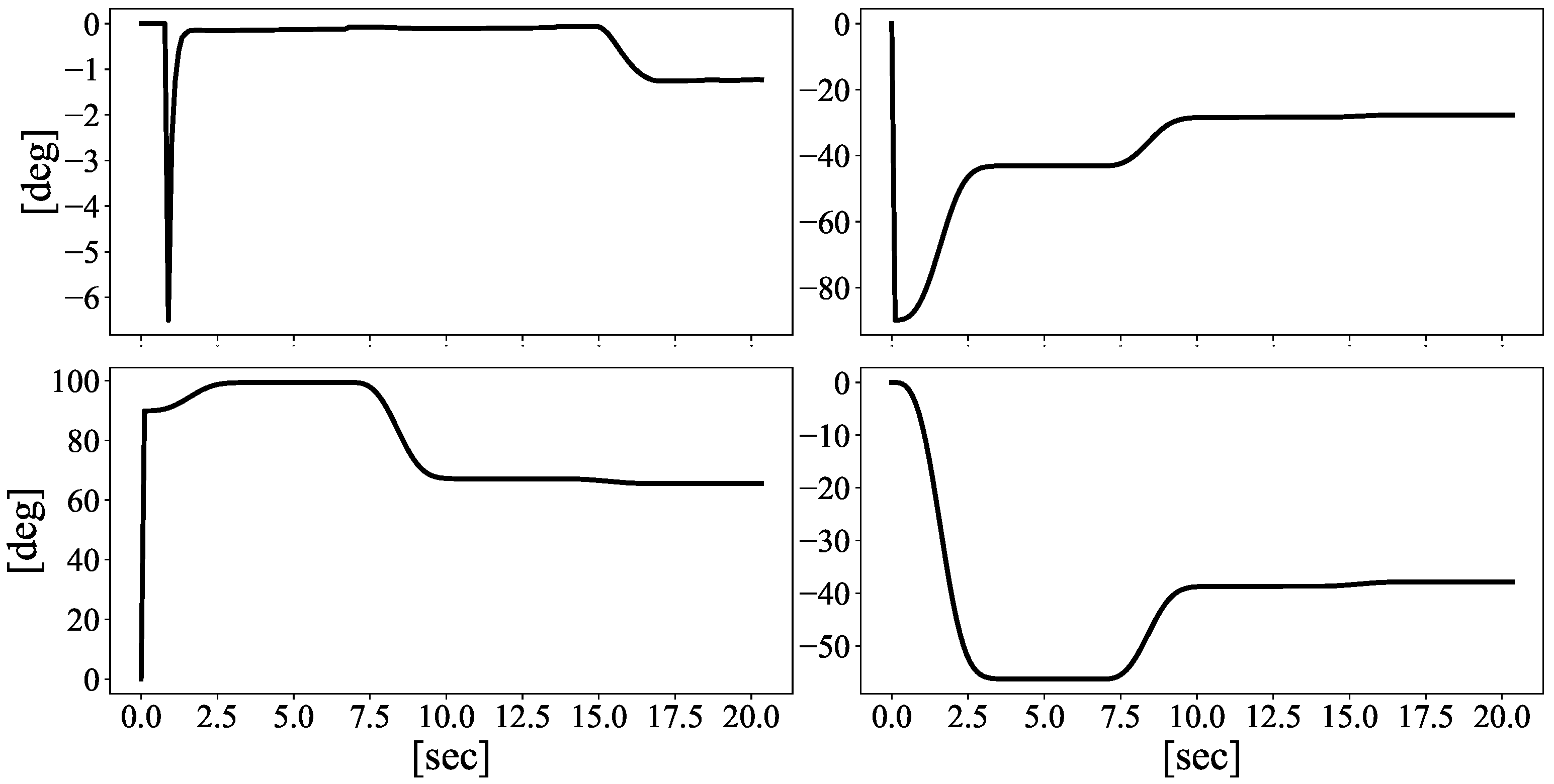
Both experiments with the attached aerial manipulators start with an approach motion to the contact point including an initial state, an approaching phase where the end-effector moves to 0.3 [m] on x e axis with respect to the airframe, and finally the contact phase as is depicted in Figure 11 and Figure 12 for the manipulators attached with a single and with two passive joints, respectively. Each manipulator joint motion is shown in Figure 13 and Figure 14, where it can be appreciated that the on-board arm joint motions are very similar, except for the passive joint linking the attaching mechanism and the UAV.
Once the end-effector makes a smooth contact on the environment located at 0.378 [m] on x e axis with respect to the airframe, then the force control is implemented, whose results are presented in Figure 15. The (a) plot shows the free-flying aerial manipulator results, as was mentioned above; it can be appreciated how it could effectively deliver up to 8 [N]. The controlled force supplied by the aerial manipulator attached with a single passive joint is depicted in the (b) plot, where it can be appreciated that it effectively delivered up to 50 [N] with some overshoots. The (c) plot shows the force delivered by the aerial manipulator attached with two passive joints, where it can be noticed that it reached up to 50 [N] as well but with some mismatch-recovery events caused by the reactionary forces affecting the robot manipulator, as it can be appreciated in the experiments video. Notice that the larger the delivered force, the noisier the measured signal as a consequence of the effects of the reactionary forces incoming from the rigid environment acting on each robotic setup. For the case of the aerial manipulators attached to the environment, it can be seen that the reactionary forces do not affect the delivered forces below 30 [N] in contrast to the free-flying setup, which is clearly affected from 6 [N]. Of course, these realistic results are proper for the experiment’s execution on a physics-engine-based simulator, which could hardly be obtained with classical numerical simulation approaches or simple three-dimensional visualizers. Hence, from a qualitative perspective, it can be noticed that the aerial manipulator with a single passive joint attached overcomes its two-passive-joints counterpart. Notwithstanding, the root-mean-squared error (RMSE) and average convergence time were taken into account and listed in Table 4 in order to have a quantitative comparison, where it can be realized that both indices are smaller for the case of the aerial manipulator attached with a single passive joint.

6. Conclusions

In this work, a comprehensive study of horizontal force delivery capabilities of aerial manipulators was conducted to demonstrate that leveraging the environment increases them with respect to flying freely. The analysis consisted of evaluating the Generalized-Jacobian-based force ellipsoids for free-flying and attached-to-the-environment types of aerial manipulators. Unlike the traditional kinematic-Jacobian-based force ellipsoids, the employed tool is trustful in determining force delivery capabilities of aerial manipulators, because it takes into account the kinematics and inertial properties of the robot as well as the reaction forces incoming from the on-board arm’s motion.
The aforementioned analysis was performed numerically by an extensive simulation campaign for the following aerial manipulator setups: free-flying with a stick on board, free-flying with a 3-DOF arm on board, UAV attached to the environment through a single passive joint with a 3-DOF arm on board and UAV attached to the environment through two passive joints with a 3-DOF arm on board. Among the four setups, the aerial manipulator attached with a single passive joint presented the largest Generalized-Jacobian-based force ellipsoids, followed by the two-passive-joints attached aerial manipulator, which demonstrates that leveraging the environment increases horizontal force delivery capabilities contrary to flying freely.
In order to prove the theoretical results, physics-engine-based simulations of controlled force delivery with aerial manipulators were carried out within the Gazebo software. This time, only the aerial manipulator with a stick was considered among free-flying setups, whereas both the other attached setups were included in the comparison. Meanwhile, the free-flying setup was able to deliver up to 8 [N] horizontal force, and the attached systems achieved up to 50 [N], showing superior controlled force delivery capacity. The aerial manipulator attached with a single passive joint overcame the performance of its two-passive-joints counterpart, attaining the best-controlled force delivery capabilities among all setups.
This research work established a meaningful instrument for the analysis and design of aerial manipulators by incorporating well-known tools, namely the Generalized Jacobian and the force ellipsoids. Through this analysis, it was concluded that leveraging the environment increases the force delivery capabilities of aerial manipulators after both theoretical and experimental work. In addition, several research paths my arise given these insights, such as determining the optimal joint configuration for larger force delivery, developing better force control techniques or combining the UAV and the arm motions to perform motion/force control, among other possibilities.
Originally, attached-to-the-environment aerial platforms were part of the work of the Aerial-Core European Project (https://aerial-core.eu/, accessed on 25 September 2024), which aims to develop aerial robots endowed with several ranges of capabilities for power lines inspection and maintenance; in this case, the presented robots are thought for electrical insulator brushing. However, this technology can be extended to the inspection and maintenance of photovoltaic infrastructure, harbor facilities or wind turbines among other possible facilities that require the application of large sustained forces for long periods in hazardous or inaccessible areas. Finally, it is well known that developing aerial manipulators capable of rigidly attaching to the environment might be considerably expensive and for such a reason, the scope of this paper is limited only to trustworthy physics-engine-based simulations. Nonetheless, these presented successful results are the basis of new developments that are currently being carried out.

Author Contributions

Conceptualization, S.M.O.S.; methodology, S.M.O.S.; software, S.M.O.S.; validation, S.M.O.S.; formal analysis, S.M.O.S.; investigation, S.M.O.S.; resources, V.L.; data curation, S.M.O.S.; writing—original draft preparation, S.M.O.S.; writing—review and editing, V.L.; visualization, S.M.O.S.; supervision, V.L.; project administration, V.L.; funding acquisition, V.L. All authors have read and agreed to the published version of the manuscript.

Funding

The research leading to these results was supported by the AERIAL-CORE project (Horizon 2020 Grant Agreement No. 871479). The authors are solely responsible for its content.

Data Availability Statement

Data are contained within the article.

Acknowledgments

The National Researcher Candidate with CVU No. 319148 thanks the National Humanities, Science and Technology Council (CONAHCYT) for the support given.

Conflicts of Interest

The author declares no conflicts of interest.

References

  1. Cacace, J.; Orozco-Soto, S.M.; Suarez, A.; Caballero, A.; Orsag, M.; Bogdan, S.; Vasiljevic, G.; Ebeid, E.; Rodriguez, J.A.A.; Ollero, A. Safe Local Aerial Manipulation for the Installation of Devices on Power Lines: AERIAL-CORE First Year Results and Designs. Appl. Sci. 2021, 11, 6220. [Google Scholar] [CrossRef]
  2. Kessens, C.C.; Horowitz, M.; Liu, C.; Dotterweich, J.; Yim, M.; Edge, H.L. Toward lateral aerial grasping & manipulation using scalable suction. In Proceedings of the 2019 International Conference on Robotics and Automation (ICRA), Montreal, QC, Canada, 20–24 May 2019; pp. 4181–4186. [Google Scholar]
  3. Ortenzi, V.; Adjigble, M.; Kuo, J.A.; Stolkin, R.; Mistry, M. An experimental study of robot control during environmental contacts based on projected operational space dynamics. In Proceedings of the 2014 IEEE-RAS International Conference on Humanoid Robots, Madrid, Spain, 18–20 November 2014; pp. 407–412. [Google Scholar]
  4. Umetani, Y.; Yoshida, K. Resolved Motion Rate Control of Space Manipulators with Generalized Jacobian Matrix. Ph.D. Thesis, Tohoku University, Sendai, Japan, 1989. [Google Scholar]
  5. Ikeda, T.; Ohara, K.; Ichikawa, A.; Ashizawa, S.; Oomichi, T.; Fukuda, T. Aerial manipulator control method based on generalized jacobian. J. Robot. Mechatronics 2021, 33, 231–241. [Google Scholar] [CrossRef]
  6. Umetani, Y.; Yoshida, K. Continuous path control of space manipulators mounted on OMV. Acta Astronaut. 1987, 15, 981–986. [Google Scholar] [CrossRef]
  7. Lee, M.Y.; Erdman, A.G.; Gutman, Y. Kinematic/kinetic performance analysis and synthesis measures of multi-DOF mechanisms. Mech. Mach. Theory 1993, 28, 651–670. [Google Scholar] [CrossRef]
  8. Mermertaş, V. Optimal design of manipulator with four-bar mechanism. Mech. Mach. Theory 2004, 39, 545–554. [Google Scholar] [CrossRef]
  9. Cinquemani, S.; Giberti, H.; Legnani, G. The generalized jacobian matrix and the manipulators kinetostatic properties. In Proceedings of the ASME 10th Biennial Conference on Engineering Systems Design and Analysis (ESDA), Istanbul, Turkey, 12–14 July 2010; pp. 721–729. [Google Scholar]
  10. Hu, J.; Wang, T. Minimum base attitude disturbance planning for a space robot during target capture. J. Mech. Robot. 2018, 10, 051002. [Google Scholar] [CrossRef]
  11. Thomas, J.; Loianno, G.; Daniilidis, K.; Kumar, V. Visual servoing of quadrotors for perching by hanging from cylindrical objects. IEEE Robot. Autom. Lett. 2015, 1, 57–64. [Google Scholar] [CrossRef]
  12. Ladig, R.; Paul, H.; Miyazaki, R.; Shimonomura, K. Aerial Manipulation Using Multirotor UAV: A Review from the Aspect of Operating Space and Force. J. Robot. Mechatronics 2021, 33, 196–204. [Google Scholar] [CrossRef]
  13. Zheng, Y.F.; Yin, Q. Coordinating multilimbed robots for generating large cartesian force. IEEE Trans. Syst. Man Cybern. 1990, 20, 849–857. [Google Scholar] [CrossRef]
  14. Yoshida, H.; Inoue, K.; Arai, T.; Mae, Y. Mobile manipulation of humanoid robots-optimal posture for generating large force based on statics. In Proceedings of the 2002 IEEE International Conference on Robotics and Automation (Cat. No. 02CH37292), Washington, DC, USA, 11–15 May 2002; Volume 3, pp. 2271–2276. [Google Scholar]
  15. Abi-Farraj, F.; Henze, B.; Ott, C.; Giordano, P.R.; Roa, M.A. Torque-based balancing for a humanoid robot performing high-force interaction tasks. IEEE Robot. Autom. Lett. 2019, 4, 2023–2030. [Google Scholar] [CrossRef]
  16. Liu, C.; Bera, A.; Tsabedze, T.; Edgar, D.; Yim, M. Spiral zipper manipulator for aerial grasping and manipulation. In Proceedings of the 2019 IEEE/RSJ International Conference on Intelligent Robots and Systems (IROS), Macau, China, 3–8 November 2019; pp. 3179–3184. [Google Scholar]
  17. Papachristos, C.; Alexis, K.; Tzes, A. Efficient force exertion for aerial robotic manipulation: Exploiting the thrust-vectoring authority of a tri-tiltrotor uav. In Proceedings of the 2014 IEEE international conference on robotics and automation (ICRA), Hong Kong, China, 31 May–7 June 2014; pp. 4500–4505. [Google Scholar]
  18. Wopereis, H.W.; Hoekstra, J.; Post, T.; Folkertsma, G.A.; Stramigioli, S.; Fumagalli, M. Application of substantial and sustained force to vertical surfaces using a quadrotor. In Proceedings of the 2017 IEEE international conference on robotics and automation (ICRA), Singapore, 29 May–3 June 2017; pp. 2704–2709. [Google Scholar]
  19. Hamaza, S.; Georgilas, I.; Richardson, T. An adaptive-compliance manipulator for contact-based aerial applications. In Proceedings of the 2018 IEEE/ASME International Conference on Advanced Intelligent Mechatronics (AIM), Auckland, New Zealand, 9–12 July 2018; pp. 730–735. [Google Scholar]
  20. Orozco-Soto, S.M.; Cuniato, E.; Cacace, J.; Selvaggio, M.; Ruggiero, F.; Lippiello, V.; Siciliano, B. Aerial manipulator interaction with the environment. In Control of Autonomous Aerial Vehicles: Advances in Autopilot Design for Civilian UAVs; Springer: Berlin/Heidelberg, Germany, 2023; pp. 319–347. [Google Scholar]
  21. Marcellini, S.; D’Angelo, S.; De Crescenzo, A.; Marolla, M.; Lippiello, V.; Siciliano, B. Development of a semi-autonomous framework for NDT inspection with a tilting aerial platform. In International Symposium on Experimental Robotics; Springer: Berlin/Heidelberg, Germany, 2023; pp. 353–363. [Google Scholar]
  22. Marcellini, S.; Cacace, J.; Lippiello, V. A PX4 Integrated Framework for Modeling and Controlling Multicopters with Til table Rotors. In Proceedings of the 2023 International Conference on Unmanned Aircraft Systems (ICUAS), Warsaw, Poland, 6–9 June 2023; pp. 1089–1096. [Google Scholar]
  23. Marcellini, S.; Ruggiero, F.; Lippiello, V. Nonlinear Model Predictive Control for Repetitive Area Reconnaissance with a Multirotor Drone. In Proceedings of the 2023 International Conference on Unmanned Aircraft Systems (ICUAS), Warsaw, Poland, 6–9 June 2023; pp. 515–522. [Google Scholar]
  24. Ullah, H.; D’Angelo, S.; Ruggiero, F.; Lippiello, V.; Orozco Soto, S.M. Horizontal Sustained Force Delivery with an Aerial Manipulator using Hybrid Force/Position Control. In Proceedings of the 25th IEEE International Carpathian Control Conference (ICCC), Krynica Zdrój, Poland, 22–24 May 2024; pp. 1–5. [Google Scholar]
  25. Tsukagoshi, H.; Watanabe, M.; Hamada, T.; Ashlih, D.; Iizuka, R. Aerial manipulator with perching and door-opening capability. In Proceedings of the 2015 IEEE International Conference on Robotics and Automation (ICRA), Seattle, WA, USA, 26–30 May 2015; pp. 4663–4668. [Google Scholar]
  26. Estrada, M.A.; Mintchev, S.; Christensen, D.L.; Cutkosky, M.R.; Floreano, D. Forceful manipulation with micro air vehicles. Sci. Robot. 2018, 3, eaau6903. [Google Scholar] [CrossRef] [PubMed]
  27. Boudreau, R.; Nokleby, S.; Gallant, M. Wrench capabilities of a kinematically redundant planar parallel manipulator. Robotica 2021, 39, 1601–1616. [Google Scholar] [CrossRef]
  28. Chiacchio, P.; Bouffard-Vercelli, Y.; Pierrot, F. Evaluation of force capabilities for redundant manipulators. In Proceedings of the IEEE International Conference on Robotics and Automation, Minneapolis, MN, USA, 22–28 April 1996; Volume 4, pp. 3520–3525. [Google Scholar]
  29. Yoshikawa, T. Manipulability of robotic mechanisms. Int. J. Robot. Res. 1985, 4, 3–9. [Google Scholar] [CrossRef]
  30. Yoshida, K.; Umetani, Y. Control of space manipulators with generalized Jacobian matrix. In Space Robotics: Dynamics and Control; Springer: Berlin/Heidelberg, Germany, 1993; pp. 165–204. [Google Scholar]
  31. Siciliano, B.; Khatib, O.; Kröger, T. Springer Handbook of Robotics; Springer: Berlin/Heidelberg, Germany, 2008; Volume 200. [Google Scholar]
  32. Spong, M.W.; Hutchinson, S.; Vidyasagar, M. Robot Modeling and Control; John Wiley & Sons: Hoboken, NJ, USA, 2020. [Google Scholar]
  33. Orozco Soto, S.M.; Ruggiero, F.; Lippiello, V. Globally attractive hyperbolic control for the robust flight of an actively tilting quadrotor. Drones 2022, 6, 373. [Google Scholar] [CrossRef]
  34. Polverini, M.P.; Formentin, S.; Merzagora, L.; Rocco, P. Mixed data-driven and model-based robot implicit force control: A hierarchical approach. IEEE Trans. Control Syst. Technol. 2019, 28, 1258–1271. [Google Scholar] [CrossRef]
Figure 1. Aerial manipulator kinematics.
Robotics 13 00147 g001
Figure 2. Aerial manipulators in study.
Robotics 13 00147 g002
Figure 3. Kinematic parameters of the attached aerial manipulators in the study. (a) Aerial manipulator attached with a single passive joint (4 DOF). (b) Aerial manipulator attached with two passive joints (5 DOF).
Robotics 13 00147 g003
Figure 4. Normal-Jacobian-based force ellipsoids of aerial manipulators. (a) Free-flying with stick. (b) Free-flying with arm. (c) Attached with a single passive joint. (d) Attached with two passive joints. Robotics 13 00147 i001 Rigid environment. Robotics 13 00147 i002 Force ellipsoid axes. Robotics 13 00147 i003 Manipulator links. Robotics 13 00147 i004 UAV.
Robotics 13 00147 g004
Figure 5. Normal-Jacobian-based force ellipsoids of aerial manipulators with actuator’s weighting. (a) Free-flying with stick. (b) Free-flying with arm. (c) Attached with a single passive joint. (d) Attached with two passive joints. Robotics 13 00147 i001 Rigid environment. Robotics 13 00147 i002 Force ellipsoid axes. Robotics 13 00147 i003 Manipulator links. Robotics 13 00147 i004 UAV.
Robotics 13 00147 g005
Figure 6. Force ellipsoids of aerial manipulators: (a) 5 kg UAV; (b) 15 kg UAV; (c) 15000 kg UAV. Robotics 13 00147 i002 Normal-Jacobian-based force ellipsoid. Robotics 13 00147 i005 Generalized-Jacobian-based force ellipsoid. Robotics 13 00147 i003 Manipulator links. Robotics 13 00147 i004 UAV.
Robotics 13 00147 g006
Figure 7. Generalized-Jacobian-based force ellipsoids of aerial manipulators. (a) Free-flying with a stick. (b) Free-flying with arm. (c) Attached with a single passive joint. (d) Attached with two passive joints.
Robotics 13 00147 g007
Figure 8. Horizontal axis averages and standard deviations of Generalized-Jacobian-based force ellipsoids. Stick: Free-flying with stick. FF: Free-flying with arm. A1PJ: Attached with a single passive joint. A2PJ: Attached with two passive joints.
Robotics 13 00147 g008
Figure 9. Block diagram of the physics-engine-based simulation setup and control software for controlled force delivery assessment.
Robotics 13 00147 g009
Figure 10. Block diagram of the position−based implicit force control for attached aerial manipulators. The discrete−time dependency of the variables has been dropped for simplicity.
Robotics 13 00147 g010
Figure 11. Motion phases of the aerial manipulator attached to the environment with a single passive joint before force control.
Robotics 13 00147 g011
Figure 12. Motion phases of the aerial manipulator attached to the environment with two passive joints before force control.
Robotics 13 00147 g012
Figure 13. Time evolution of the joints of the aerial manipulator attached to the environment with a single passive joint during the reaching phase. Up left: q 0 . Up right: q 1 . Down left: q 2 . Down right: q 3 .
Robotics 13 00147 g013
Figure 14. Time evolution of the joints of the aerial manipulator attached to the environment with two passive joints during the reaching phase. Up left: q 1 . Up right: q 2 . Down left: q 3 . Down right: q 4 .
Robotics 13 00147 g014
Figure 15. Controlled delivered force with aerial manipulators. (a) Free-flying (Data obtained from [24]). (b) Attached with a single passive joint. (c) Attached with two passive joints. Robotics 13 00147 i006 Desired force. Robotics 13 00147 i007 Measured force.
Robotics 13 00147 g015
Table 1. Results available in the literature for aerial manipulators delivering large sustained forces.
WorkRobot FeaturesAchieved ForceTime Sustained
Free-flying aerial manipulators
Papachristos et al. (2014) [17]2.254 [kg] UAV with 1-DOF end-effectorEstimated 18 [N]30 [s]
Wopereis et al. (2017) [18]1.5 [kg] UAV with rod end-effectorEstimated 14 [N]240 [s]
Hamaza et al. (2018) [19]2 [kg] UAV rod 2-DOF end-effectorMeasured 60 [N]1.5 [s]
Orozco et al. (2023) [20]5 [kg] UAV with 3-DOF manipulatorMeasured 2.2 [N]80 [s]
Ullah et al. (2024) [24]5 [kg] UAV with 3-DOF manipulatorMeasured 8 [N]120 [s]
Perched aerial manipulators
Tsukagoshi (2015) [25]Experimental results with 1.7 [kg] UAV with soft-bag actuated end-effectorEstimated 4 [Nm] torquen/a
Estrada (2018) [26]Experimental results with 200 [g] UAV and winchLifted 40 [N]n/a
Table 2. Kinematic parameters of the aerial manipulators.
ParameterFree-FlyingAttached with OneAttached with Two
Passive Joint Passive Joints
l 0 0.380.45
l 1 0.20.20.38
l 2 0.20.20.2
l 3 0.060.060.2
l 4 0.06
Table 3. Generalized-Jacobian-based force capabilities analysis data.
DataFree-Flying withFree-Flying withAttached with OneAttached with Two
Stick Moving Arm Passive Joint Passive Joints
Average0.51560.37560.64530.6140
Variance0.00.00030.00990.0055
Std. deviation0.00.01750.09990.0744
Table 4. Data of controlled delivered forces with attached aerial manipulators.
DataAttached with OneAttached with Two
Passive Joint Passive Joints
RMSE3.847.49
AVG Convergence time22.5 s49.2 s
Disclaimer/Publisher’s Note: The statements, opinions and data contained in all publications are solely those of the individual author(s) and contributor(s) and not of MDPI and/or the editor(s). MDPI and/or the editor(s) disclaim responsibility for any injury to people or property resulting from any ideas, methods, instructions or products referred to in the content.