Abstract
Trajectory interception is a critical synchronization element in the transportation and manufacturing sectors using robotic platforms. This is usually performed by matching the position and velocity of a target object with the position and velocity of the robot interceptor. However, the synchronization task is exasperated by (i) the proper gain tuning of the controller, (ii) the dynamic response of the robotic platform, (iii) the velocity constraints in the actuators, and (iv) the trajectory profile exhibited by the moving object. This means that the interception time is not controlled, which is critical for energy optimization, resources, and production. This paper proposes a prescribed time trajectory interception algorithm for robot manipulators. The approach uses the finite-time convergence properties of sliding mode control combined with a terminal attractor based on a time base generator. The combined approach guarantees trajectory interception in a prescribed time with robust properties. Simulation studies are conducted using the first three degrees of freedom (DOFs) of a RV-M1 robot under single- and multi-object interception tasks. The results verify the effectiveness of the proposed methodology under different hyperparameter configurations.
1. Introduction
Trajectory interception is one of the most common tasks in the transport and manufacturing sectors involving robots. Some potential applications include pick and place [1], maneuvers in combat [2], deceiving targets [3], synchronization [4] and, recently, encryption of communication tasks [5]. In these tasks, time is an important element that needs to be considered in the control design to minimize error threats due to delays in the interception. The most simple control approaches use linear models to predefine the convergence time [6,7]. Also, feedback linearization controllers or dynamic inversion approaches [8] have been considered to first linearize the system dynamics and then apply classic linear control approaches for trajectory interception. This means that knowledge of the dynamics of the robot is required to obtain the control gains that inject a desired behavior and closed-loop performance. However, the model is usually uncertain, and applying feedback linearization controllers is prohibitive due to the inherent modeling error of model-based controllers [9]. On the other hand, model-free controllers such as PD, PID, or sliding mode control (SMC) [10,11] can ensure finite time convergence, but the convergence is usually asymptotic, such that the robot can intercept the object either before or after a desired time.
Therefore, there is a need to ensure that the interception between a robot interceptor and a moving object occurs in a prescribed time to ensure the smooth operation of transport or manufacture operations.
1.1. Related Work
Classical approaches use guidance and navigation controllers (e.g., proportional navigation [12,13]) based on simple geometric relations for the interception of targets. Artificial potential fields [14,15] have been also used to guide autonomous systems toward the trajectory followed by the target. The key idea is to use repellent and attractive forces that suggest the direction where the target is moving. Trajectory optimization techniques, such as covariant Hamiltonian optimization for motion planning (CHOMP) [16] or stochastic trajectory optimization for motion planning (STOMP) [17], have been applied in robot manipulators for motion planning under obstacles. However, these approaches do not consider the interception time [18], which can cause the robot to miss the target or that the interception occur after the desired time.
Other navigation approaches, such as and Dijkstra algorithms [19,20,21,22], have been used to calculate an optimal/near-optimal path given some starting and ending points. These approaches assume knowledge of the workspace to find the best path. However, this is computationally intensive if the search space is large. These models are usually improved with some heuristics to reduce the search space and the computational resources [23]. Novel approaches use one-shot learning approaches [24,25] to obtain a path for the interception. These approaches combine deep autoencoders with heuristics [26] to seek a path from any starting point to an ending point under workspaces with obstacles.
Reinforcement Learning (RL) algorithms have been effectively used in interception tasks using diverse architectures ranging from simple tabular methods (e.g., Q-learning) to deep RL models (e.g., deep deterministic policy gradient (DDPG) [27] or soft actor-critic (SAC) [28]), and recently with adversarial learning [2]. The key success of these models is due to a proper reward design that covers all the possible scenarios that the robotic system can meet in the interception task. However, these methods need a large training time, and it is difficult to converge in a prescribed time.
In the last decade, different research has been developed to ensure convergence in prescribed time. The key idea is to use terminal attractors [29] that force the system trajectories to converge into a desired manifold and remain within as time advances. A time base generator (TBG) is usually used to ensure convergence in a prescribed time. Here, an S-shaped function with a parabolic derivative is used to guarantee this behavior. The S-shaped function is designed in terms of polynomials or splines [30]. However, these functions lack robustness across diverse behaviors due to the fixed form of the curves.
1.2. Contributions, Outline and Notations
This paper proposes a model-free robust controller that guarantees interception to moving objects’ trajectories in a prescribed time. The approach consists of using a robust second-order sliding mode controller (SMC) enhanced with a time base generator (TBG) for prescribed time convergence to the object trajectory. Lyapunov stability is used to assess the closed-loop stability of the approach. Diverse simulation studies are conducted to show the advantages and challenges of the proposed approach.
The main contributions of this paper are summarized as follows:
- A prescribed time interception algorithm that ensures accurate interception of the trajectories of moving objects.
- A time base generator (TBG) design that permits the control of the path followed by the robot for the interception.
- A second-order sliding mode control that forces the closed-loop trajectories to stay in the sliding surface manifold in the prescribed time given by the TBG.
The outline of this paper is as follows. Section 2 describes the proposed methodology, which includes the preliminaries, TBG design, and sliding mode control design. Section 3 shows the results of the proposed approach under different scenarios and hyperparameter settings. Conclusions are given in Section 4.
Throughout this paper, denote the spaces of natural numbers, real numbers, positive real numbers, real n-vectors, and real -matrices, respectively; is an identity matrix of dimension , and denotes the minimum and maximum eigenvalues of matrix , respectively; the norms and stand for the induced matrix and vector Euclidean norms, respectively; where , and .
2. Methodology
The proposed methodology is shown in Figure 1 as a simple visualization of the task. We consider a trajectory interception application involving a robot manipulator and objects moving in a known trajectory profile . Cameras are used to measure the position of the objects. Here, the task consists of intercepting the trajectory of each object in a pre-defined time given initial times , etc. This is achieved by (1) designing a second-order sliding mode control (SMC) that ensures convergence to the object trajectory in finite time with robust capabilities against exogenous disturbances and model uncertainty, and (2) integrating a time base terminal attractor known as time base generator (TBG) that forces the robot dynamics to intercept the object in a desired time. This means that the finite time convergence of the SMC is modified into a prescribed time control that maintains all its robust properties.

Figure 1.
Proposed methodology.
2.1. Robot Dynamic Preliminaries
Consider the dynamic model of a n-rigid robot manipulator [31]
where denotes the joint positions and angular velocities, is a positive definite inertia matrix, stands to the centripetal and Coriolis forces matrix, is the gravitational torques vector, is a bounded disturbance vector associated with dissipative terms such as friction, model uncertainties, and exogenous disturbances, and is the vector of applied torques. It is assumed that the Coriolis matrix satisfies the following Christoffel factorization
where
are the Christoffel symbols of the first kind, and denotes the component of the inertia matrix . The Coriolis matrix is skew-symmetric [32], such that it satisfies
for any . In addition, the inertia matrix , the Coriolis matrix , and satisfy
for some .
The transformation from joint space coordinates to task space coordinates is given by
where is the forward kinematics of the robot, and are the Cartesian positions and velocities, respectively, and is the Jacobian matrix.
Assumption 1.
In this paper, we consider non-redundant robots, i.e., we assume . In addition, we assume that the Jacobian matrix is full rank for any interception task and it is bounded, i.e., where is an upper bound.
Assumption 2.
In this paper, it is assumed that the dynamic parameters (e.g., mass, inertia) of the robot are unknown, whilst the kinematic parameters (e.g., length of links) are known.
The trajectories followed by the moving objects in the Cartesian space are assumed to be known in advance, and are denoted as .
2.2. Time Base Generator (TBG)
The dynamics of the TBG have the following structure:
where is a user-defined constant that shapes the behavior of the TBG, is a positive constant that ensures convergence in a pre-defined time . We can easily observe that (6) has a stable equilibrium point at and an unstable equilibrium point at . Here, we can always ensure convergence to the stable point by choosing an initial condition of , where . The convergence time can be computed as follows:
where is the Gamma function. Therefore, the constant is a function of and as
The acceleration profile of the TBG satisfies the following relation:
Notice that a bounded acceleration is obtained only if , which provides an additional constraint to . For the jerk effect, we obtain the following relation by differentiating (9)
which gives another constraint to , i.e., .
So, we can generate a family of time-varying signals by modifying the parameters and , which can serve for interception purposes. Figure 2 shows the TBG dynamics under different values under a fixed s.
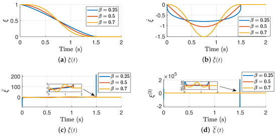
Figure 2.
Time Base Generator under different values.
The results highlight that small values of give performances that are proportional to time, which can yield to overshoots if is too small. In addition, small values for do not comply with the acceleration and jerk constraints, which can be observed as large overshoots in the prescribed time . As increases, it yields to smoother performances, without overshoots and smooth acceleration and jerk profiles. Figure 3 shows the TBG dynamics under different interception times for a fixed .
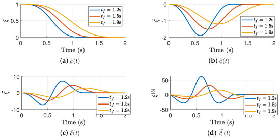
Figure 3.
Time Base Generator under different values.
Here, it is clear that modifies the time of convergence of the TBG, whilst maintaining the smooth performance injected by the value. Notice that for large interception time, gives a curve with a smaller amplitude magnitude. Conversely, for small interception time, gives large . This gives an indicator of how we can exploit the TBG dynamics in an adaptive control design. Furthermore, smooth acceleration and jerk profiles are observed in all cases which is highly useful to avoid abrupt movements of the manipulator.
2.3. Sliding Mode Control (SMC) Design
Define the interception errors as
For the sliding surface design, consider the following unforced linear time-varying (LTV) system:
where
with , and are small positive constants. Figure 4 shows how the gain changes as and evolves in time. Here, we set .

Figure 4.
Time-evolution of under different hyperparameters.
The graphs show that grows as the TBG approximates to . Here, large enough values give gains with a smaller amplitude. This is consistent with what we observed in the TBG dynamics, i.e., large values give smooth performances that attenuate the amplitude of the gain . On the other hand, the effect of is clear, since large interception time yields to smaller gains. Conversely, small interception times give large gains to ensure the interception. This behavior is exploited in the design of the sliding mode controller.
The solution of (12) satisfies the following relation:
Note that when , we have that , and
Under this condition, can be set as small as possible by selecting small enough constants and . This is quite useful for the design of the sliding surface, which forces the trajectories to maintain in the manifold and to not escape.
Based on this concept, consider the following sliding surface design:
So, based on the previous analysis, we have that when , it will imply that the interception error can be arbitrarily small. To avoid the chattering effect and enhance the robust capabilities of the SMC, we consider the following nominal sliding surface, given by
where and is a diagonal weight matrix. Notice that the additional term in the sign function ensures that we start in the sliding surface for any initial condition. Then, the following second-order sliding mode control law is used:
where is a diagonal control gain and is the Moore–Penrose pseudoinverse of the Jacobian . If we expand the terms in (18), it yields an SMC with a PID structure.
2.4. Stability Analysis
The Jacobian mapping (5) is used on the nominal sliding surface as
where denotes the nominal sliding surface in the joint space and is the time-derivative of the Jacobian, which is also bounded, i.e., where . Then, we can rewrite the closed-loop dynamics in terms of this joint space surface as
where is a state-dependent function, given by
with . Notice that
where and . Then, by using the bounds (4), we have that
Notice that contains the disturbance vector , which needs to be compensated by the sliding mode controller. The following theorem is used to verify the practical stability of the proposed approach.
Theorem 1.
Consider the closed-loop system trajectories (20). If the control gain satisfies the following relation,
where , then the trajectories of the sliding surface remains bounded in a set of radius , and the interception error converges to an arbitrarily small value in a pre-defined time .
Proof of Theorem 1.
Consider the Lyapunov function,
Using the skew-symmetric property of the Coriolis matrix gives
is negative definite if
Notice that is a function dependent of , , , and the initial conditions of the sliding surface; then, for sufficiently small initial errors [33,34] that belong to a small set of radius and are centered in , we are allowed to state that there exists a large enough gain that fulfills (22). Therefore, the nominal joint surface trajectories converge to a bounded set of radius , i.e., as . This means that is bounded.
Boundedness of and the Jacobian means that is also bounded, and converges to a bounded set of radius centered in the equilibrium . In other words, this means that is centered in the sliding surface attractor, such that all the trajectories within try to converge into the attractor. In the equilibrium point , the sliding surface verifies the unforced LTV system,
whose solution is given by
This allows to conclude that the error trajectories within will converge to an error value proportional to (25) with a lower bound of . This completes the proof. □
From the previous proof, we can observe two specific properties of the controller: (1) it converges in a prescribed time to the object trajectory, and (2) it has robust properties against model uncertainty and exogenous disturbances by choosing a large enough gain and the proper tuning of the gain . The combined contribution gives the proposed approach a unique mechanism to ensure convergence in a prescribed time with robust capabilities.
Remark 1.
The gain Λ is manually tuned, and plays an important role of the performance of the overall controller. Here, the product of defines the nonlinear gain of the integral term of the proposed SMC controller. This term is in charge of maintaining the closed-loop trajectories within the sliding manifold, whilst attenuating the model uncertainties and disturbances.
Remark 2.
The computational complexity of the proposed controller is dominated by the product between the inverse of the Jacobian and the control gain , given by .
3. Results
In this section, we report the results of the proposed approach in the interception of objects in diverse trajectory profiles. Specifically, we consider the following cases: an object following a curve trajectory and a multiple interception task in a robotic assembly task. All computations are executed on an Intel(R) Core(TM) i9-10885H 2.40 GHz, 32 GB RAM, with Matlab/Simulink 2023b and RoboDk 5.7 software. Both Matlab and RoboDK are connected through the RoboDK API. Here, Matlab/Simulink is used for the control design and encoding the robot dynamics, whilst RoboDK is used to obtain a visual representation of the robot and the interception of the target in the Cartesian coordinates.
3.1. RV-M1 Robot
We consider the Mitsubishi RV-M1 robot observed in Figure 5.
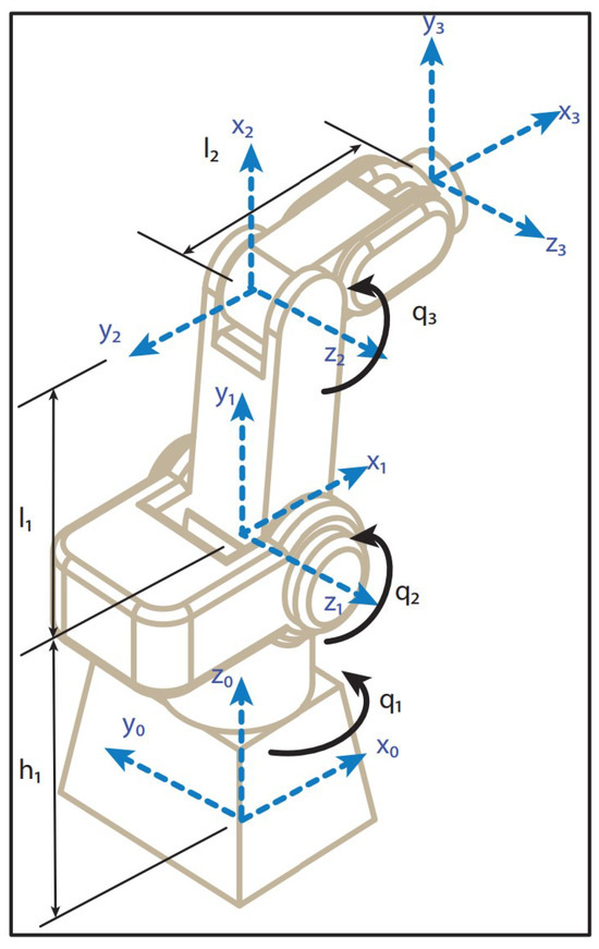
Figure 5.
Mitsubishi RV-M1 robot.
The RV-M1 robot is a 5 DOF robot; however, in this paper we only use the first three DOF that control the position of the manipulator, as in [35]. These joint angles are used since the goal of this research is to ensure the interception of the object in a prescribed time regardless its orientation. The control of both the position and orientation for target interception in a prescribed time is topic for future research.
The kinematics of the first three DOF of the RV-M1 robot is given by
where denote the joint angles, defines the Cartesian position, and and define the length of each link, with .
The associated Jacobian matrix is given by
where
The kinematic parameters of the robot are m, m and m. The dynamic parameters have been estimated by the 3D Computer-Aided Design (CAD) drawing of the robot. These parameters are used for simulation purposes. The control gains and parameters of the TBG used in this paper are: , , and . The robot model considers friction at the robot joints and complete dynamic model uncertainty.
3.2. Curve Trajectory
We test the approach under an object following a curve trajectory, defined by
In this case, we aim to observe how the hyperparameters of the TBG, i.e., and affect the performance of the interception algorithm. Consider first the scenario of a fixed interception time of s. We compare the results using .
3.2.1.
Figure 6 shows the trajectory interception for .
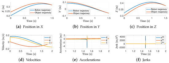
Figure 6.
Trajectory interception in each axis. Results for = 1.5 s and .
The results show that, as we previously discussed, a small makes the robot intercept the object almost linearly. This linear performance produces discontinuous velocities which in consequence shows large accelerations and jerk peaks. Figure 7 shows the 3D interception task between the robot and the object trajectories.
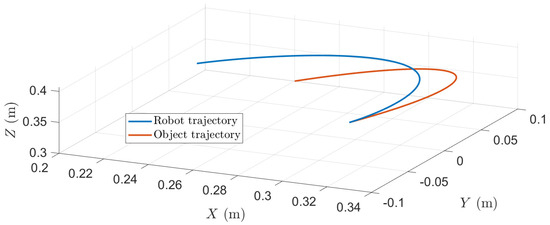
Figure 7.
3D trajectory interception. Results for = 1.5 s and .
3.2.2.
Consider the case where . Figure 8 shows the interception trajectories in the Cartesian space.
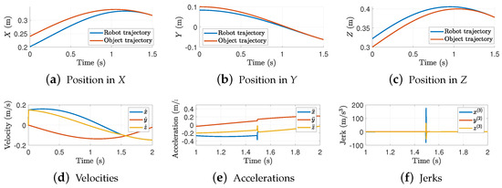
Figure 8.
Trajectory interception in each axis. Results for = 1.5 s and .
Notice that similar results are obtained in the previous case. In this case, offers a smoother evolution of the TBG, i.e., the velocity discontinuities are smaller such that the acceleration and jerk amplitudes are decreased. Figure 9 shows the 3D interception trajectory.
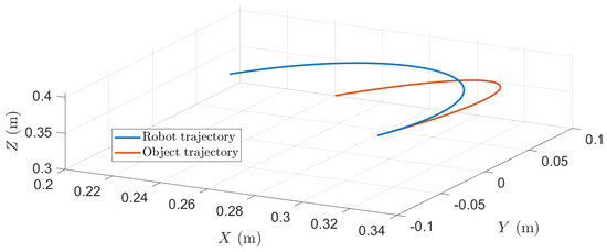
Figure 9.
3D trajectory interception. Results for = 1.5 s and .
3.2.3.
Figure 10 shows the interception task for a .
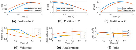
Figure 10.
Trajectory interception in each axis. Results for = 1.5 s and .
In contrast to the previous cases, when the TBG is smoother, such that it has a large that causes the robot to follow a larger trajectory path. However, the robot intercepts the object’s trajectory at an early point. This is better observed in the 3D trajectory of Figure 11, where it is shown that the robot adopts a larger path, but converges in the pre-defined time in an early point of the object trajectory. Notice that the acceleration and jerk effects are notably reduced, which gives an indicator that values close to 1 will give trajectories without peaks in acceleration and jerk.

Figure 11.
3D trajectory interception. Results for = 1.5 s and .
3.2.4. = 1.2 s
In this case, we maintain fixed to and modify the interception time. Figure 12 shows the trajectory interception for an interception time of s.
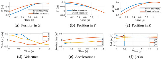
Figure 12.
Trajectory interception in each axis. Results for = 1.2 s and .
In this case, we are forcing the robot to intercept the object faster such that it needs to increase to obtain a larger . This means that the trajectory will follow a linear trajectory profile that yields to peaks in accelerations and jerks. Figure 13 shows the 3D-interception trajectory. From the graph, it can be observed that the robot takes longer to intercept the object in the pre-defined time . However, as in the previous case, it intercepts the object at an early point, which can lead to issues if the interception is required at a specific point.
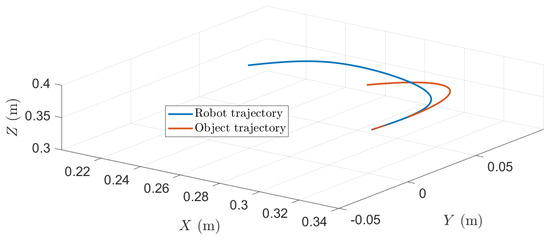
Figure 13.
3D trajectory interception. Results for = 1.2 s and .
3.2.5. s
Figure 14 shows the interception of the trajectory in a pre-defined time s. In this scenario, the robot follows a larger path with a slower that causes the robot to converge in the pre-defined time but intercepts at an early point. Here, both the acceleration and jerk trajectories exhibit a smooth profile with small overshoots due to the interception.
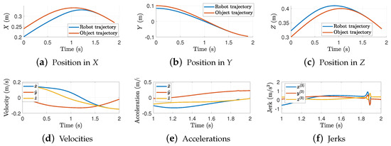
Figure 14.
Trajectory interception in each axis. Results for = 1.9 s and .
Figure 15 shows the 3D-trajectory interception. This case is more evident since the robot follows a large trajectory and converges in the pre-defined time to an early point, whilst the position of the object at time is at a forward position.

Figure 15.
3D trajectory interception. Results for = 1.9 s and .
3.3. Multiple Interception in Robotic Assembly Tasks
The proposed approach is challenged in a robotic assembly task. The approach consists of the interception (pick and place) of objects coming from different conveyors. Traditional approaches use different robots to pick objects from their respective conveyor. Here, we aim to reduce the necessity of multiple robots by using a unique robot dedicated to the pick and place of objects in a prescribed time. In this study, we assume the objects have the same orientation such that the robot can pick them without modifying the joint angles of the wrist, i.e., we only use the first three DOF joints of the robot for the pick and place task. Future work will consider objects with different orientations such that the interception task is more challenging.
The proposed experiment consists of the picking and placing of three objects coming from three different conveyors. Each object is assumed to have a constant velocity of m/s in the y-axis. The trajectories and positions of each conveyor are summarized in Table 1.

Table 1.
Conveyors trajectories in (m).
The initial position of the gripper is m. For the object in conveyor 1, we set an interception time of s to pick the object and wait s to pick the second object in the conveyor 2 in an interception time of s. After this, the robot waits s to pick the third object in a time of s. Figure 16 shows the velocity error for the proposed assembly task.
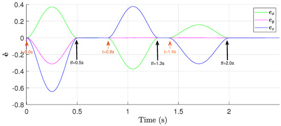
Figure 16.
Cartesian velocity error in the assembly task.
Notice that for each interception trajectory, the Cartesian velocity error converges in the prescribed times . For short interception times (object 1), the gain increases such that the robot follows a faster path given by a large to converge in the desired time. On the other hand, for large interception times (object 3), has a low gain that produces a short path that smoothly converges in the prescribed time .
Figure 17 shows how the torques change each time the TBG is applied. Notice that the torques remain bounded and stable, which shows how the torques slightly increase for short interception times and small values for long interception times. Figure 18 shows the trajectories of the robot throughout the assembly task. Notice that, since the trajectories are not continuous, discontinuous accelerations are obtained, which yield large jerks. However, this is a common pattern in robot manipulators when they start from an initial condition that is relative far from the desired position. This is usually attenuated by adding a low-pass filter in each new target interception goal. This will create a smooth trajectory profile that the robot will be able to handle in a smoother way.
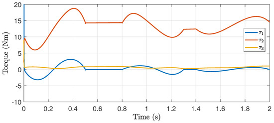
Figure 17.
Torques applied to the robot.
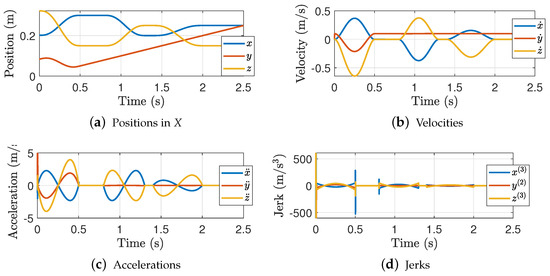
Figure 18.
Robot trajectories for the assembly task.
Figure 19 shows the trajectory profile of the robot for the interception of the three objects in the prescribed times. Here, the trajectory followed by the robot is smooth and continuous, this demonstrates the benefits of the proposed technique and the reduction in resources and time.
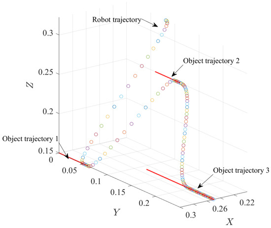
Figure 19.
Multiple interception trajectories.
4. Conclusions
This paper proposes a novel interception algorithm for moving objects using robot manipulators. The task is achieved by using a novel time base generator that allows the interception in a prescribed time. Here, we introduce a new parameter that modifies the behavior of the TBG according to the task and prescribed time. A second-order sliding mode controller is designed to ensure tracking of the object and robustness against modeling errors and uncertainties. The proposed sliding-mode controller adopts a TBG-based varying gain to ensure the closed-loop trajectories converge and remain within the sliding manifold. The stability and boundedness of the closed-loop system trajectories are verified using Lyapunov stability theory. Diverse simulation studies using a RV-M1 robot model are conducted to show the advantages of the proposed approach in the interception of objects in prescribed time. Two cases were considered: an object following a curved trajectory and a multi-interception task. The results demonstrate the feasibility and robustness of the approach to intercept objects in different prescribed times and tasks. Future work will consider the extension of the proposed approach when either the trajectories of the objects are unknown or when these trajectories do not follow a repetitive pattern. Furthermore, future research will include the interception of objects with different orientations.
Author Contributions
Conceptualization, J.A.F.-C. and A.P.; methodology, J.A.F.-C.; software, C.R.T.-S.-M.; validation, J.C.P.-R., J.A.F.-C. and A.P.; formal analysis, J.A.F.-C.; investigation, A.P.; resources, J.C.P.-R.; writing—original draft preparation, A.P.; writing—review and editing, A.P.; visualization, C.R.T.-S.-M.; supervision, A.P.; project administration, J.A.F.-C.; funding acquisition, A.P. All authors have read and agreed to the published version of the manuscript.
Funding
This research received funding under projects: SIP 20240710, SIP 20240701, and SIP 20242785.
Institutional Review Board Statement
Not applicable.
Informed Consent Statement
Not applicable.
Data Availability Statement
The original contributions presented in the study are included in the article material, further inquiries can be directed to the corresponding author.
Conflicts of Interest
The authors declare no conflicts of interest.
Abbreviations
The following abbreviations are used in this manuscript:
| CAD | Computer-Aided Design |
| CHOMP | Covariant Hamiltonian optimization for motion planning |
| DDPG | Deep Deterministic Policy Gradient |
| DOF | Degree of Freedom |
| RL | Reinforcement Learning |
| SAC | Soft Actor Critic |
| SMC | Sliding Mode Control |
| STOMP | Stochastic trajectory optimization for motion planning |
| TBG | Time Base Generator |
References
- Lobbezoo, A.; Qian, Y.; Kwon, H.J. Reinforcement learning for pick and place operations in robotics: A survey. Robotics 2021, 10, 105. [Google Scholar] [CrossRef]
- Wang, L.; Hu, J.; Xu, Z.; Zhao, C. Autonomous maneuver strategy of swarm air combat based on DDPG. Auton. Intell. Syst. 2021, 1, 15. [Google Scholar] [CrossRef]
- Meng, X.; Sun, B.; Zhu, D. Harbour protection: Moving invasion target interception for multi-AUV based on prediction planning interception method. Ocean. Eng. 2021, 219, 108268. [Google Scholar] [CrossRef]
- Flores-Campos, J.A.; Perrusquía, A.; Hernández-Gómez, L.H.; González, N.; Armenta-Molina, A. Constant speed control of slider-crank mechanisms: A joint-task space hybrid control approach. IEEE Access 2021, 9, 65676–65687. [Google Scholar] [CrossRef]
- Guo, W.; Wei, Z.; Gonzalez, O.; Perrusquía, A.; Tsourdos, A. Control layer security: A new security paradigm for cooperative autonomous systems. IEEE Veh. Technol. Mag. 2023, 99, 2–11. [Google Scholar] [CrossRef]
- Ye, H.; Song, Y. Prescribed-time control for linear systems in canonical form via nonlinear feedback. IEEE Trans. Syst. Man Cybern. Syst. 2022, 53, 1126–1135. [Google Scholar] [CrossRef]
- Zhou, B.; Zhang, Z.; Michiels, W. Functional and dual observer based prescribed-time control of linear systems by periodic delayed feedback. Automatica 2024, 159, 111406. [Google Scholar] [CrossRef]
- Friedman, A.; Friedman, A. Dynamic Inversion and Control of Nonlinear Systems. In Mathematics in Industrial Problems; Springer: New York, NY, USA, 1988; pp. 114–120. [Google Scholar]
- Hou, Z.S.; Wang, Z. From model-based control to data-driven control: Survey, classification and perspective. Inf. Sci. 2013, 235, 3–35. [Google Scholar] [CrossRef]
- Moreira, M.; Papp, E.; Ventura, R. Interception of non-cooperative UAVs. In Proceedings of the 2019 IEEE International Symposium on Safety, Security, and Rescue Robotics (SSRR), Wurzburg, Germany, 2–4 September 2019; IEEE: Piscataway, NJ, USA, 2019; pp. 120–125. [Google Scholar]
- Wenjie, Z.; Shengnan, F.; Wei, L.; Qunli, X. An impact angle constraint integral sliding mode guidance law for maneuvering targets interception. J. Syst. Eng. Electron. 2020, 31, 168–184. [Google Scholar]
- Li, Y.; Yan, L.; Zhao, J.g.; Liu, F.; Wang, T. Combined proportional navigation law for interception of high-speed targets. Def. Technol. 2014, 10, 298–303. [Google Scholar] [CrossRef]
- Sinha, A.; Kumar, S.R.; Mukherjee, D. Cooperative integrated guidance and control design for simultaneous interception. Aerosp. Sci. Technol. 2022, 120, 107262. [Google Scholar] [CrossRef]
- Tsuji, T.; Tanaka, Y.; Morasso, P.G.; Sanguineti, V.; Kaneko, M. Bio-mimetic trajectory generation of robots via artificial potential field with time base generator. IEEE Trans. Syst. Man, Cybern. Part (Appl. Rev.) 2002, 32, 426–439. [Google Scholar] [CrossRef]
- Duhé, J.F.; Victor, S.; Melchior, P. Contributions on artificial potential field method for effective obstacle avoidance. Fract. Calc. Appl. Anal. 2021, 24, 421–446. [Google Scholar] [CrossRef]
- Ratliff, N.; Zucker, M.; Bagnell, J.A.; Srinivasa, S. CHOMP: Gradient optimization techniques for efficient motion planning. In Proceedings of the 2009 IEEE International Conference on Robotics and Automation, Kobe, Japan, 12–17 May 2009; IEEE: Piscataway, NJ, USA, 2009; pp. 489–494. [Google Scholar]
- Kalakrishnan, M.; Chitta, S.; Theodorou, E.; Pastor, P.; Schaal, S. STOMP: Stochastic trajectory optimization for motion planning. In Proceedings of the 2011 IEEE iNternational Conference on Robotics and Automation, Shanghai, China, 9–13 May 2011; IEEE: Piscataway, NJ, USA, 2011; pp. 4569–4574. [Google Scholar]
- Kumar, S.R.; Mukherjee, D. Terminal time-constrained nonlinear interception strategies against maneuvering targets. J. Guid. Control. Dyn. 2021, 44, 200–209. [Google Scholar] [CrossRef]
- Zhaoying, L.; Ruoling, S.; Zhao, Z. A new path planning method based on sparse A* algorithm with map segmentation. Trans. Inst. Meas. Control. 2022, 44, 916–925. [Google Scholar] [CrossRef]
- Li, Z.; Li, H. Study of the interception scheme based on A* path finding algorithm in computer game. J. Comput. Commun. 2020, 8, 32–49. [Google Scholar] [CrossRef]
- Khachiyan, L.; Gurvich, V.; Zhao, J. Extending dijkstra’s algorithm to maximize the shortest path by node-wise limited arc interdiction. In Proceedings of the Computer Science–Theory and Applications: First International Computer Science Symposium in Russia, CSR 2006, St. Petersburg, Russia, 8–12 June 2006; Proceedings 1. Springer: Berlin/Heidelberg, Germany, 2006; pp. 221–234. [Google Scholar]
- Luo, M.; Hou, X.; Yang, J. Surface optimal path planning using an extended Dijkstra algorithm. IEEE Access 2020, 8, 147827–147838. [Google Scholar] [CrossRef]
- Candra, A.; Budiman, M.A.; Hartanto, K. Dijkstra’s and a-star in finding the shortest path: A tutorial. In Proceedings of the 2020 International Conference on Data Science, Artificial Intelligence, and Business Analytics (DATABIA), Medan, Indonesia, 16–17 July 2020; IEEE: Piscataway, NJ, USA, 2020; pp. 28–32. [Google Scholar]
- Bian, T.; Xing, Y.; Zolotas, A. End-to-End One-Shot Path-Planning Algorithm for an Autonomous Vehicle Based on a Convolutional Neural Network Considering Traversability Cost. Sensors 2022, 22, 9682. [Google Scholar] [CrossRef]
- Kulvicius, T.; Herzog, S.; Lüddecke, T.; Tamosiunaite, M.; Wörgötter, F. One-shot multi-path planning for robotic applications using fully convolutional networks. In Proceedings of the 2020 IEEE International Conference on Robotics and Automation (ICRA), Paris, France, 31 May–31 August 2020; IEEE: Piscataway, NJ, USA, 2020; pp. 1460–1466. [Google Scholar]
- Ha, J.S.; Park, Y.J.; Chae, H.J.; Park, S.S.; Choi, H.L. Adaptive path-integral autoencoders: Representation learning and planning for dynamical systems. Adv. Neural Inf. Process. Syst. 2018, 31, 124008. [Google Scholar] [CrossRef]
- Du, Y.; Zhang, X.; Cao, Z.; Wang, S.; Liang, J.; Zhang, F.; Tang, J. An optimized path planning method for coastal ships based on improved DDPG and DP. J. Adv. Transp. 2021, 2021, 7765130. [Google Scholar] [CrossRef]
- Nasonov, I.; Galyaev, A.; Medvedev, A. Neural Network Algorithm for Intercepting Targets moving along known trajectories by a Dubins’ car. arXiv 2023, arXiv:230406169v1. [Google Scholar]
- Azar, A.T.; Serrano, F.E. Stabilization of port Hamiltonian chaotic systems with hidden attractors by adaptive terminal sliding mode control. Entropy 2020, 22, 122. [Google Scholar] [CrossRef] [PubMed]
- Domínguez Ramírez, O.A.; Parra Vega, V.; Díaz Montiel, M.G.; Pozas Cárdenas, M.J.; Hernández Gómez, R.A. Cartesian Sliding PD Control of Robot Manipulator for Tracking in Finite Time: Theory and Experiments; DAAAM International: Viena, Austria, 2008; pp. 257–272. [Google Scholar]
- de Wit, C.C.; Siciliano, B.; Bastin, G. Theory of robot control; Springer Science & Business Media: Berlin/Heidelberg, Germany, 2012. [Google Scholar]
- Perrusquía, A.; Flores-Campos, J.A.; Torres-San-Miguel, C.R. A novel tuning method of PD with gravity compensation controller for robot manipulators. IEEE Access 2020, 8, 114773–114783. [Google Scholar] [CrossRef]
- Spong, M.W.; Thorp, J.S.; Kleinwaks, J.M. Robust microprocessor control of robot manipulators. Automatica 1987, 23, 373–379. [Google Scholar] [CrossRef]
- Abdallah, C.; Dawson, D.M.; Dorato, P.; Jamshidi, M. Survey of robust control for rigid robots. IEEE Control. Syst. Mag. 1991, 11, 24–30. [Google Scholar]
- Kumar, R.; Kalra, P.; Prakash, N.R. A virtual RV-M1 robot system. Robot.-Comput.-Integr. Manuf. 2011, 27, 994–1000. [Google Scholar] [CrossRef]
Disclaimer/Publisher’s Note: The statements, opinions and data contained in all publications are solely those of the individual author(s) and contributor(s) and not of MDPI and/or the editor(s). MDPI and/or the editor(s) disclaim responsibility for any injury to people or property resulting from any ideas, methods, instructions or products referred to in the content. |
© 2024 by the authors. Licensee MDPI, Basel, Switzerland. This article is an open access article distributed under the terms and conditions of the Creative Commons Attribution (CC BY) license (https://creativecommons.org/licenses/by/4.0/).