Abstract
Wire harness manufacturing in the aeronautic sector is highly manual work, with production defined by multiple references and small batches. Although complete automation of the production process is not feasible, a robot-assisted approach could increase the efficiency of the existing production means. This paper presents a novel dual-arm robotic solution for workbench configuration and cable routing during the initial steps of wire harness manufacturing. Based on the CAD information of the wire harness, the proposed framework generates trajectories in real-time to complete the initial manufacturing tasks, dividing automatically the whole job between both robots. The presented approach has been validated in a production environment using different wire harness references, obtaining promising results and metrics.
1. Introduction
Recent advances in technology allow the introduction of robotics in many industrial fields, increasing the automation level of many industries. Even so, there are still sectors where the fabrication is mainly manual due to the specific features of the production. Wire harness manufacturing [1,2] in the aeronautic sector, characterized by a large number of different references and the small size of the batches, provides a challenging scenario for robotization.
As in other industrial sectors with a high percentage of manual work, the loss of information that occurs from the product design phase to the production stage significantly increases the time required for its elaboration. Specifically, in wire harness manufacturing for the aeronautic sector, the product engineers initially define the CAD drawing used as the template for production, as well as the process information on the different wires (e.g., identification, wire path…). Unfortunately, in the production stage operators analyze and re-interpret all this information to start working on the wire harness manufacturing, spending a large amount of time consulting information defined during the design phase. Besides, the small size of the batches penalizes this aspect as manufacturers will not be able to learn the specifications of all the different variants.
The presented paper proposes a CAD-based robot programming [3,4] framework that links the CAD design phase with the initial steps of production, enabling automatic workbench configuration and wire routing based on the CAD information. Using the information extracted from the drawing, the robotic system can generate robot trajectories in runtime and execute the workbench arrangement and cable routing automatically. Additionally, the system has been extended to allow the use of a dual-arm robot configuration able to cope with the large size of the wire harnesses. The approach has been validated and tested in a production environment with promising results. The main contributions of the presented paper can be summarized as:
- First implementation of a CAD-based robot programming framework for wire harness manufacturing in the aeronautic sector.
- Cable routing planner extended to manage dual-arm robot setups.
- Integrated calibration procedure to adapt the system to inaccuracies on the manufacturing workbench preparation.
The paper is organized as follows. Section 2 provides information about related work. The scenario is described in Section 3. Section 4 presents the proposed approach, including the different modules of the architecture. Section 5 and Section 6 describe the details of the offline programming application and real-time robot execution framework. Details about the implementation of the solution are given in Section 7. Section 8 provides further information about the validation experiments carried out to test the suitability of the proposed approach. Finally, Section 9 contains information about the conclusions and future work.
2. Related Work
CAD-based robot programming is a long-time paradigm [3,5] applied in many different industrial sectors. From welding [6,7,8] to spraying [9,10,11], several works took advantage of the CAD information of the parts and pieces to generate robot trajectories. Even so, the approach is usually found in scenarios without uncertainty where the placement of all the elements of the application is perfectly known beforehand.
Extending the previous approach to manage uncertainties, Bi and Lang [12] propose a software system consisting of a data-processing system and an automatic programming module for coating; the framework is capable of generating accurate surface models from points cloud based on the CAD model information. Additionally, Neto et al. [13] present a CAD-based human-robot interface that allows non-expert users to teach a robot and include sensory feedback to minimize the effects of uncertainty. In both cases, the solutions are based on single-robot setups.
Focusing on the use of robotics with wire harnesses, the assembly of wire harnesses is the most studied field with several approaches even in the early days of robotics [14]. Recently, Jian et al. [15] presented an engineering attempt to utilize multiple robot arms in the assembly of wire harnesses, validating it in a simplified scenario. Following a different direction, Palomba et al. [16] propose the use of collaborative robotics for the assembly, leaving the complex task of wire handling to human operators while the robot performs the taping operations. Continuing with the use of collaborative robots, Navas et al. [17] suggest the use of cobots to reduce ergonomic risks for wire harness assembly workers. Dual-arm approaches can also be found in the literature like the work presented by Zhang et al. [18] where a closed-loop bin-picking system focused on entangled wire harnesses is presented. Lv et al. [19] also present a dynamic model to control deformable linear objects (DLO) for single and dual-arm configurations.
In recent years, the use of Deep Learning techniques gained popularity in the wire harness manipulation field, especially for its use in the perception of the wire harness. For instance, Nguyen et al. [20] propose a Deep Learning-based data processing pipeline for automated optical inspection of wiring harnesses using real and synthetic point clouds. Additionally, Huang et al. [21] present a solution based on Deep Learning that includes a strategy for untangling deformable linear objects. Even so, the lack of general wire harness datasets for the model generation is an obstacle to the application of these techniques although several works propose solutions to speed up the creation of datasets [22,23].
Concentrating on the aerospace sector, Tunstel et al. [24] present a collaborative robot endowed with advanced intelligence and vision-guided control for wire pinning together with a human technician. Additionally, Guo et al. [25] propose an algorithm based on bidirectional searching and geometrically constrained sampling for the assembly of aircraft cables, adding mechanisms for overcoming obstacles in the high dimensional planning space. Even so, after revising the literature, the authors did not find any work proposing a CAD-based robot programming approach for wire harness manufacturing in the aeronautic sector. Although many works present models and algorithms for specific tasks, the presented paper tackles the complete production pipeline from CAD programming to robotic execution of manufacturing tasks.
3. Scenario Description
Wire harness manufacturing for the aeronautic sector is a complex scenario where the production is characterized by a large number of references and a small size of the batches (almost unitary in many cases). Besides, the manufacturing is entirely manual and the process can take up to a month in the case of the largest wire harnesses.
The process starts in the design office where engineers receive the CAD information of the wire harness from the customers. These references are transformed into a 2D drawing, which is normally placed in a way that fits the sizes of the workbenches and maximizes the used surface (e.g., a straight wire harness is placed describing a U shape). Additionally, all the information about every single wire is listed on a document, defining its path and the placement of the connectors.
Once all this information is ready, all the wires and connectors are sent to the production area alongside a drawing printed on 1:1 scale and the document with the wire information. With all the parts and documentation available, operators start with the manufacturing process, following the next operation sequence:
- Initially, operators adhere the drawing to the workbench to use it as a template.
- Operators configure the workbench by placing some pins in some specific points of the drawing like endpoints and bifurcations to guide the wires. The placement of these pins can be observed on the left part of Figure 1, positioned on the inner part of the curve, and are crucial to maintaining the shape of the wire harness.
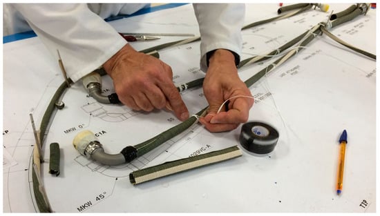 Figure 1. Operator working on the wire harness using the 2D drawing as a template.
 - When the workbench is prepared, operators start checking all the wire information documents to select the appropriate wires and start guiding them along the drawing. This production step can take a long time as operators need to constantly study the provided documentation to verify the initial and final points of each wire and its route, especially when they are not familiar with the produced reference.
- Once all the wires are routed, operators perform different tasks like cable torching, connector welding, and placement of protection. Figure 1 shows an operator securing a set of wires with a cord.
This workflow highlights the impact of information loss from CAD design to production. All the information generated by the CAD designers, which could be used to automatize some steps of manufacturing, is diluted in the process and forces operators to review the documents over and over again during the production phase. Therefore, a CAD-based robot programming solution could enhance significantly the wire harness manufacturing process.
4. Proposed Approach
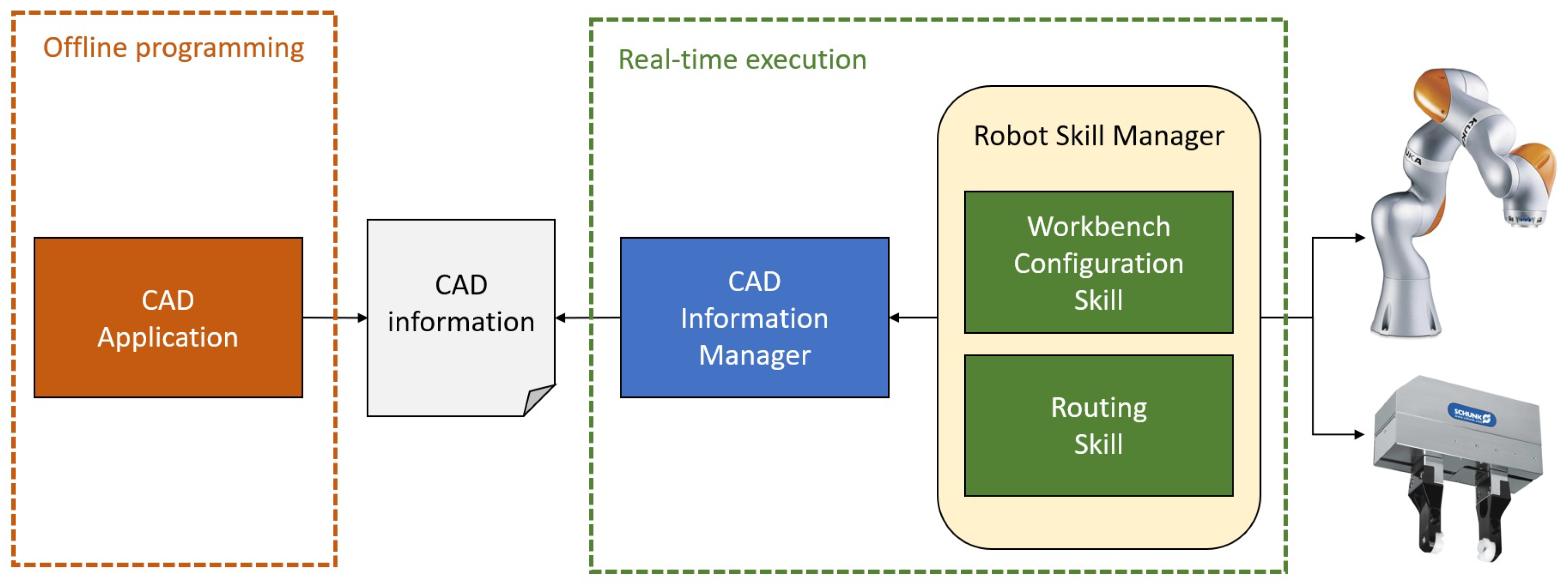
Based on the specific features of the wire harness manufacturing scenario, this paper proposes an architecture to carry out the initial steps of the manufacturing process, specifically the workbench configuration and cable routing. As stated in the previous section, one of the main drawbacks of the actual production flow is that the CAD information generated by the product designers is diluted in the process, forcing operators to verify this same information constantly. Therefore, the main objective of the proposed approach is to offer a complete architecture linking the CAD-based robot programming with real-time task execution, avoiding this information loss. Thus, a two-step workflow is proposed: (1) offline programming for data extraction from CAD models and (2) real-time execution of robot tasks based on CAD data, as shown in Figure 2.
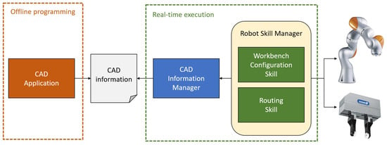
Figure 2.
General schema of the proposed approach.
In the initial phase, an Offline Programming Framework assists product designers in defining the main elements of the wire harness such as wire paths, endpoints, and pin placement points. The module allows interaction with the CAD models, extracting the required information by clicking on the 2D drawing of each reference. As a result, several XML files are generated for the Real-Time Execution Framework of the robotic system.
In the second phase, the Real-Time Execution Framework allows acquiring the information generated in the offline programming phase and using it to configure the workbench and route the cables. Specifically, the framework includes two different modules, one to load the CAD information and transform it to the robotic coordinate system and a second module offering workbench configuration and routing skills [26,27,28]. These modules allow the interpretation of the CAD information and reconfiguring robot trajectories in real time based on the received data.
The next sections provide further information on the Offline Programming Framework and Real-Time Execution Framework.
5. Offline Programming Framework
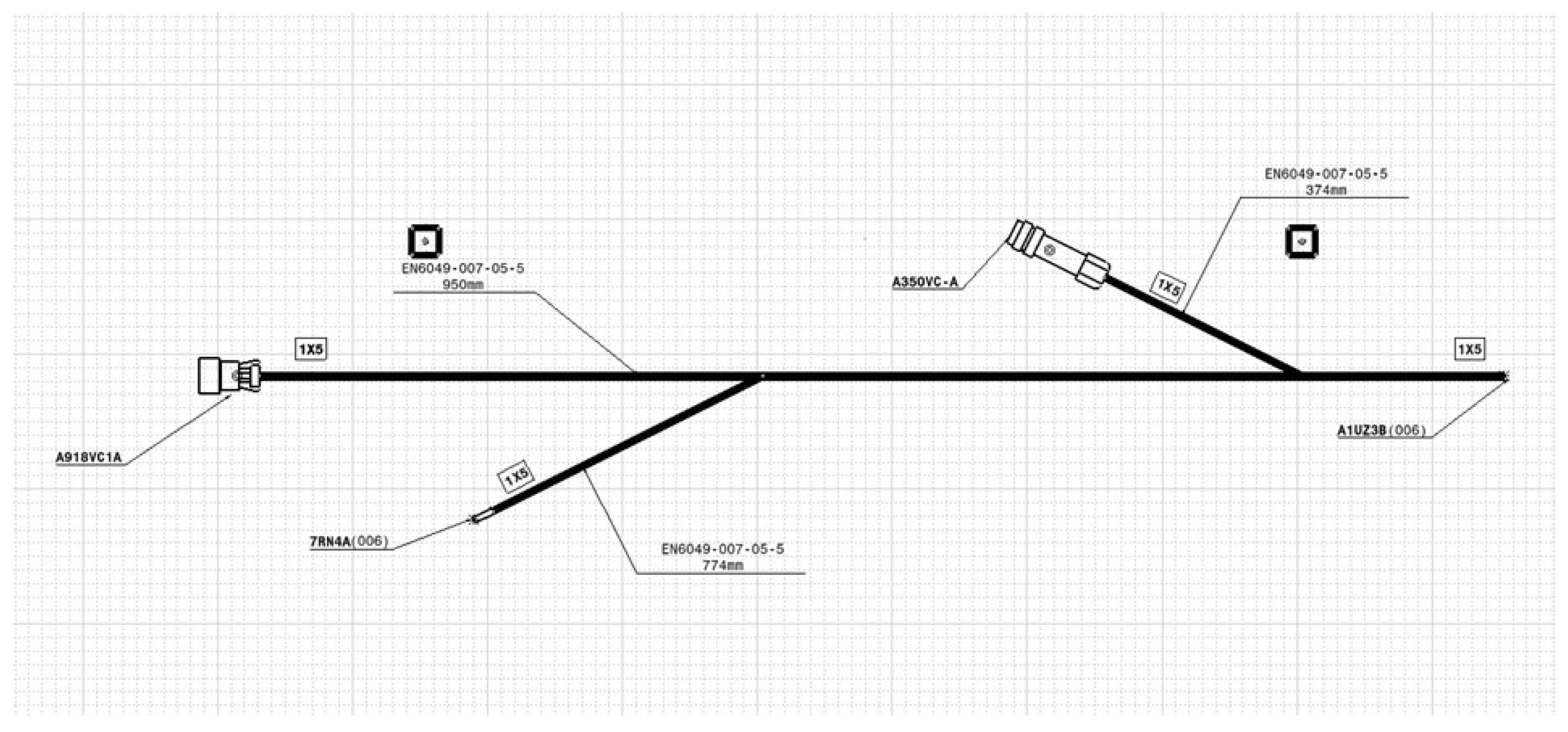
As presented in previous sections, the starting point of manual wire harness manufacturing is a 2D CAD drawing of the reference to be manufactured. Currently, this drawing is printed in 1:1 scale and it is attached to the workbench to start with the manufacturing process. The main idea is to use this same 2D drawing for programming the robot using the offline programming paradigm as shown in Figure 3.
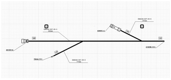
Figure 3.
2D drawing of a wire harness.
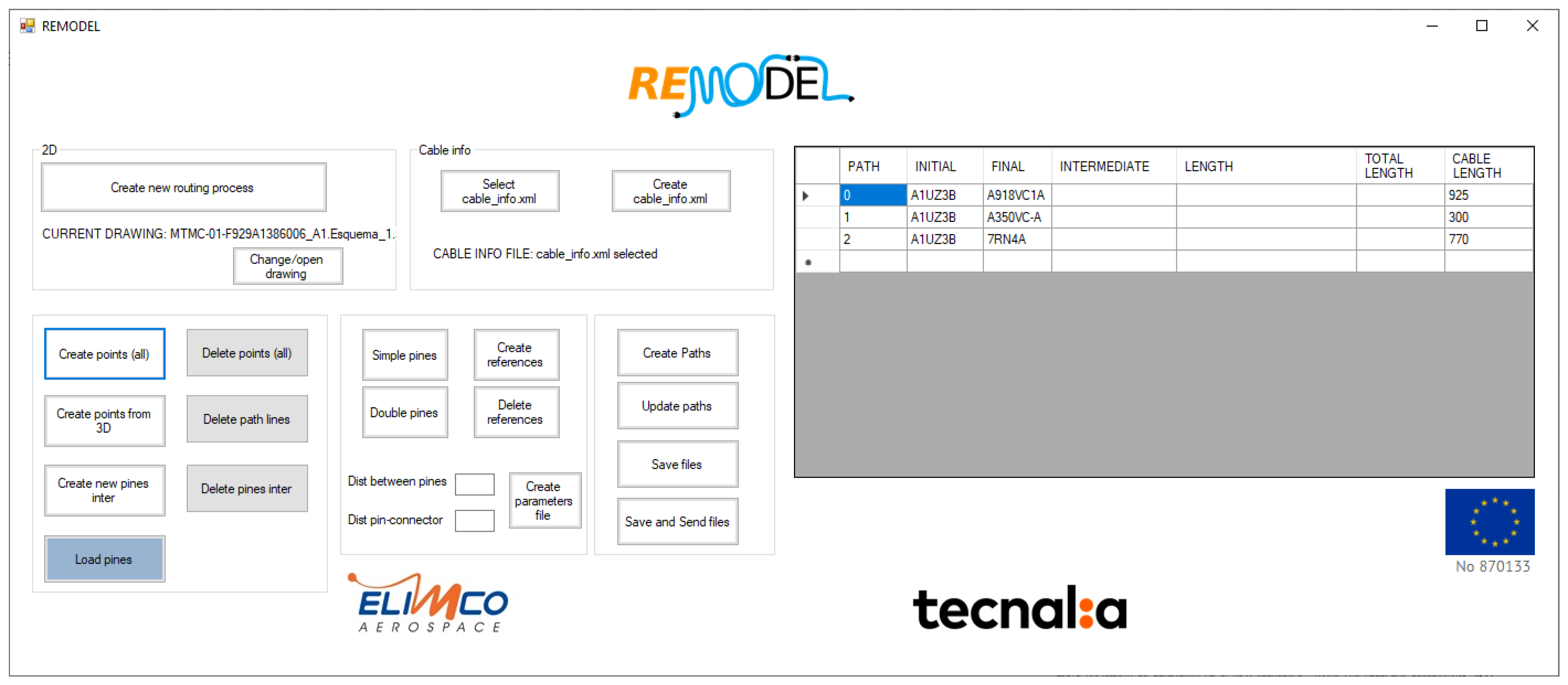
Specifically, an application is proposed to interact with the CAD software and extract information about the relevant positions of the wire harness to be sent to the robotic system, see Figure 4.
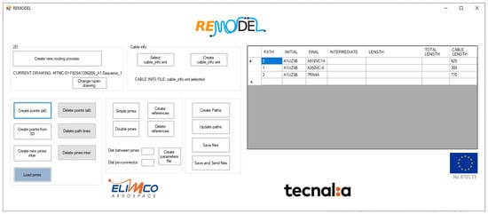
Figure 4.
Application for data extraction from 2D wire harness drawing.
During manual production, operators pay particular attention to the endpoints, as well as to the intersections. Therefore, the application allows defining these points intuitively in the drawing just by clicking on the desired position. It will generate a set of points P in the CAD coordinate system,
where each of the points is defined by a translation vector . As the application uses a 2D drawing, all the Z values of the vectors are set to 0. Even so, any desired value could be assigned to the vectors’ Z element, creating different layers, although this option was omitted in this implementation. These points will be used both for cable routing as well as for CAD calibration in further steps.
Once all the relevant points are specified, the user will be able to define different paths along the points, describing the possible routes for the cables in the wire harness, as shown in the example of Figure 5. Thus, a set of paths Q will be generated,
where each path is a subset of P and defines the complete cable route from start to end.
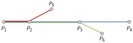
Figure 5.
Example of different routes in a set of points in the drawing.
Finally, each of the cables of the wire harness is assigned to a specific path . As each cable has a unique identifier , a list of pairs will define the assignation of each of the K cables to a unique path,
These set of P points, Q paths, and L pairs will be exported in XML format to be exploited by the Real-Time Execution Framework.
6. Real-Time Execution Framework
Once the Offline Programming Framework generates the required wire harness information, the Real-Time Execution Framework makes use of all this data to generate robot trajectories to configure the workbench and route the cables. The main idea is to use the same setup in these two initial manufacturing steps, even for different wire harness types, and without any additional modification from operators.
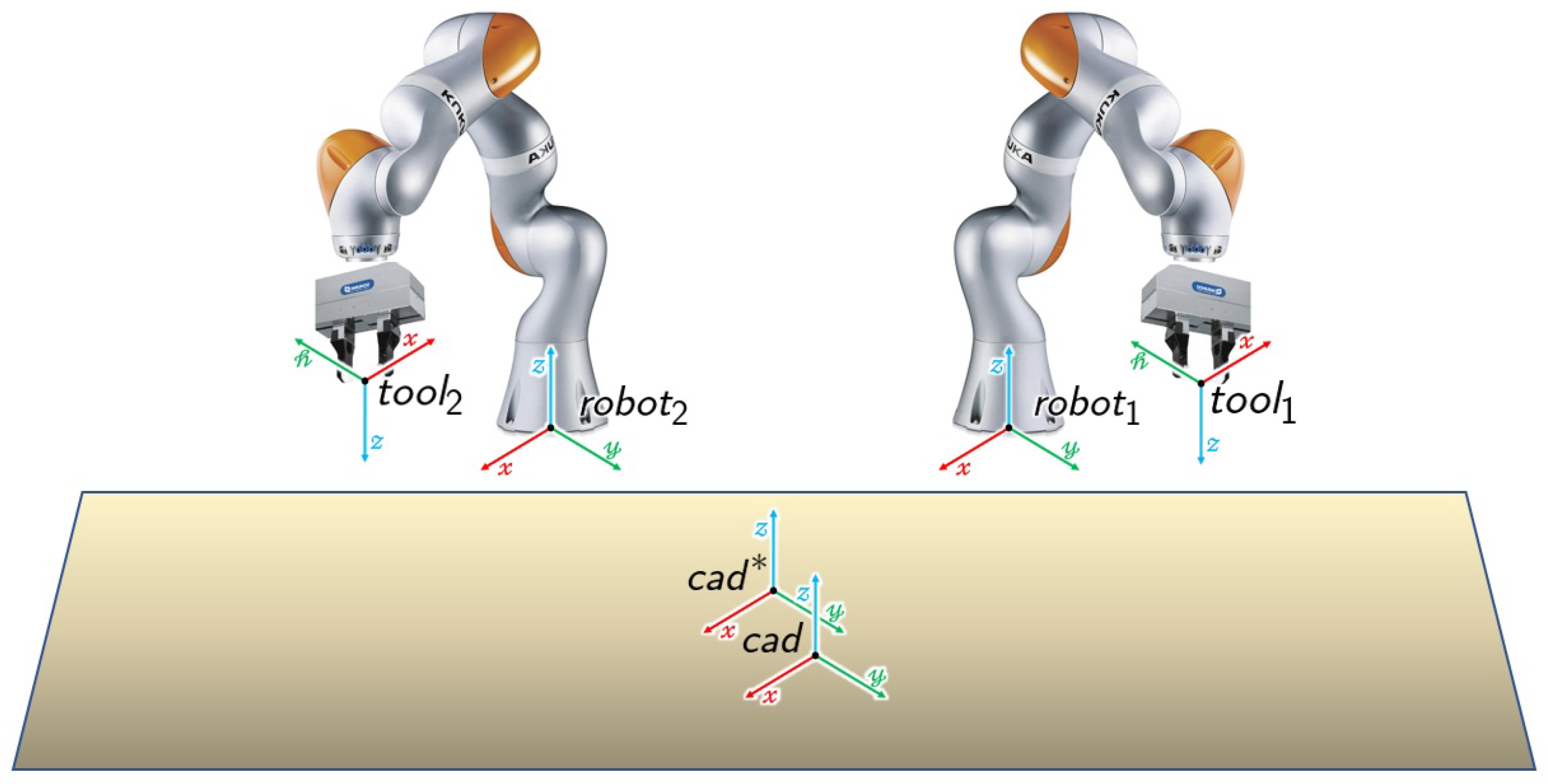
Nevertheless, it is necessary to calibrate the robot setup to have knowledge of the geometric information of the different elements of the dual-arm robotic layout. Specifically, the following transformations and coordinate systems are defined in the robot cell, as shown in Figure 6:
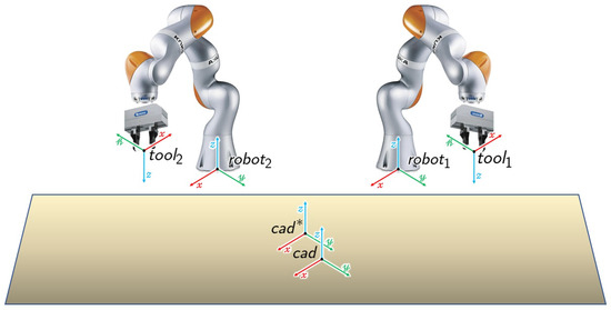
Figure 6.
Coordinate systems of the dual-arm robotic setup.
- There is a nominal CAD origin in the workbench, which is calibrated for each robot of the dual-arm system. Therefore, homogeneous transformation matricesdefine both the position and orientation of the nominal CAD origin in each robot’s base frame.
- As it is complex to place manually a 2D drawing precisely in the robot cell’s CAD origin, the Real-Time Execution Framework includes a CAD calibration step. This CAD calibration will calculate the offset between the nominal CAD coordinate system and the real CAD origin, an offset generated due to small errors in the placement of the drawing on the workbench. Transformation matrixrepresents this offset both in translation and orientation.
- To ensure the capability to modify the robot tools and adapt the robot movements accordingly, matrixdefine the transformation between the flange of the robots and each of their tools’ TCP.
- Finally, each robot has a pin feeder near its baseto provide the pins that will be placed in the CAD drawing, as well as a cable dispenser nearwith a calibrated pose to grasp each of the i cables available.
The presented coordinate systems and transformation matrices define the dual-arm robot setup used for wire harness manufacturing. The availability of this information allows a fast and reliable adaptation to modifications in the layout, requiring only updating the coordinate system information to rearrange the application.
Finally, the Real-Time Execution Framework relies on two modules (Figure 2) to perform the different tasks necessary to configure the workbench and route the cables:
- CAD Information Manager: This module is in charge of managing all the CAD data received from the Offline Programming Framework in XML file format. Specifically, the module loads the XML files and offers different queries to get information about pin positions and routing paths. Additionally, due to the errors in the positioning of 2D drawings on the workbench, this module provides a function for calculating the offset matrix based on the position of calibration points in the drawing and the position of the robots.
- Robot Skill Manager: This second module is in charge of managing the robots and grippers, offering different skills to perform each of the steps of the assembly process. Specifically, there are two different skills available: (1) configuration of the workbench by placing the routing pins in the selected points of the CAD drawing and (2) routing of the cables based on the defined paths.
The next paragraphs provide further details about the modules mentioned above and their functionalities.
6.1. CAD Information Manager
As stated previously, the main purpose of this module is to provide the CAD information generated in the Offline Programming Framework and make it available for its use in the real-time execution of the robot application. Specifically, the module offers several functions and queries for its use by the Real-Time Execution Framework:
- Load XML files: To ensure a real-time reconfiguration, the module allows loading XML files defining the CAD points, paths, and cable-path pairs. If several wire harness references are available, users can switch between them selecting the appropriate XML files at any time.
- Query CAD points: The Robot Skill Manager can ask for information about the different CAD points defined in the offline programming phase. This information is used in further steps for pin positioning and routing operations.
- Query path information: The Robot Skill Manager can ask for information about the CAD points of a specific path . This information is used for the routing skill.
- Query cable information: The Robot Skill Manager can ask for information about the path assigned for a specific cable identifier , used for routing purposes.
Additionally, the CAD Information Manager offers the functionality for calibrating the CAD origin of the drawing placed on the workbench. As the drawing is placed manually, there will always be an error between the nominal CAD origin defined in the robotic system and the real one. Therefore, this functionality allows calculating the offset transformation . To simplify its use, the idea is to guide the robots to some calibration points defined in the CAD drawing; the system calculates the offset transformation based on the calibration points and the current robot position. The next lines describe the process:
- Initially, the operator guides the robots manually to the calibration points marked in the drawing that is placed on the workbenchwhere T defines the translation vectors of the calibration points in the CAD coordinate system,
- Once the robots are placed correctly on the calibration points, the system retrieves the robot’s status, specifically the robot posesdefining the transformation matrix between each robot’s origin and the flange. Additionally, setup calibration matrices , , , and are retrieved.
- At this point, it is necessary to estimate the offset between the nominal CAD origin and the real one, to ensure thatwhere and define only the translation vector of the transformation matrix. To this end, an optimization algorithm is applied due to the expected errors in the calculus of the TCP of each tool and the robot positioning on the calibration points by operators. The optimization algorithm allows the minimization of all the possible error sources during the calculus of the matrix.Specifically, a nonlinear least-squares solver [29] is implemented allowing to solve problems of the formwhere the expression defines the residual block where is the cost functions for parameters .In the posed problem, the parameter block is defined aswhere values , , and define the translation values of matrix and values , , , and define the values of the quaternion of the rotation between the nominal CAD origin and the real CAD origin.Additionally, residual block r is defined aswhere the initial three residuals define the difference between position and the first calibration point position and residuals define the difference between position and the second calibration point position.Based on these parameter blocks and residual blocks, the nonlinear least-squares solver calculates the transformation between the nominal CAD origin defined in the workbench and the real CAD origin of the drawing placed on the workbench.
These functionalities described above enable the further execution of the workbench configuration and cable routing by the Robot Skill Manager module.
6.2. Robot Skill Manager
The Robot Skill Manager module offers different capabilities or skills to assist operators during the initial wire harness manufacturing steps. These skills can manage the data provided by the CAD Information Manager, generate robot trajectories based on this data, and finally move the robots and activate grippers to accomplish the tasks. Specifically, the Robot Skill Manager offers these two capabilities:
- Workbench Configuration Skill: As presented previously in the scenario description, it is necessary to place some pins at specific points of the workbench to guide the cable routing and maintain the shape of the cables and branches for further manufacturing steps. Therefore, this skill receives the pin positions defined by the designers on the Offline Programming Framework and places the pins on the drawing in the indicated positions. To enhance its usability, the skill includes object symmetry management mechanisms as well as collision detection capabilities to sequence the pin placement movements ensuring collision-free movements.
- Routing Skill: During the routing process, operators guide the cables along the different paths, using the pins to conduct the wires and maintain the shape of the wire harness. In each pin, it is necessary to decide through which side of the pin the path will follow; sometimes it is mandatory to select one of the sides (e.g., sharp curves always from the outer side) but at some points the decision is arbitrary. Additionally, as both robots of the bi-manual system need to exchange the cable, it is also necessary to select this exchange point. Therefore, this skill must generate and execute trajectories able to cope with these restrictions, ensuring the reachability of both robot arms for any arbitrary wire harness configuration.
The Robot Skill Manager includes internal modules to assist both skills in making different calculations, as shown in Figure 7. On the one hand, a Cartesian path planner [30] analyses the reachability and generates robot trajectories from a Cartesian point sequence; both skills query the module to calculate the required trajectories. On the other hand, a collision detection library (Flexible Collision Library [31] used through Moveit [32]) determines the feasibility of executing different robot trajectories simultaneously without any collision risk; the Workbench Configuration Skill queries the module to generate collision-free movement sequences. Additionally, the robot and gripper drivers allow moving the arms and gripper fingers based on the provided commands. These four internal modules enable the skills to plan tasks and execute them safely.
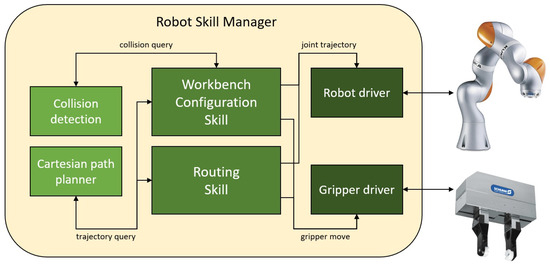
Figure 7.
Internal architecture of the Robot Skill Manager.
The next paragraphs describe the details of each skill, providing further details of the different calculations and step sequences.
6.2.1. Workbench Configuration Skill
The Workbench Configuration Skill receives the pin position set P as input. Initially, it determines which robot places each pin to divide and speed up the task. Afterwards, all the pin placement trajectories are calculated, determining if it is possible to execute them in parallel or if it would cause any collision between the robots. Finally, all the robot movements are executed and the grippers are activated as determined in the plan.
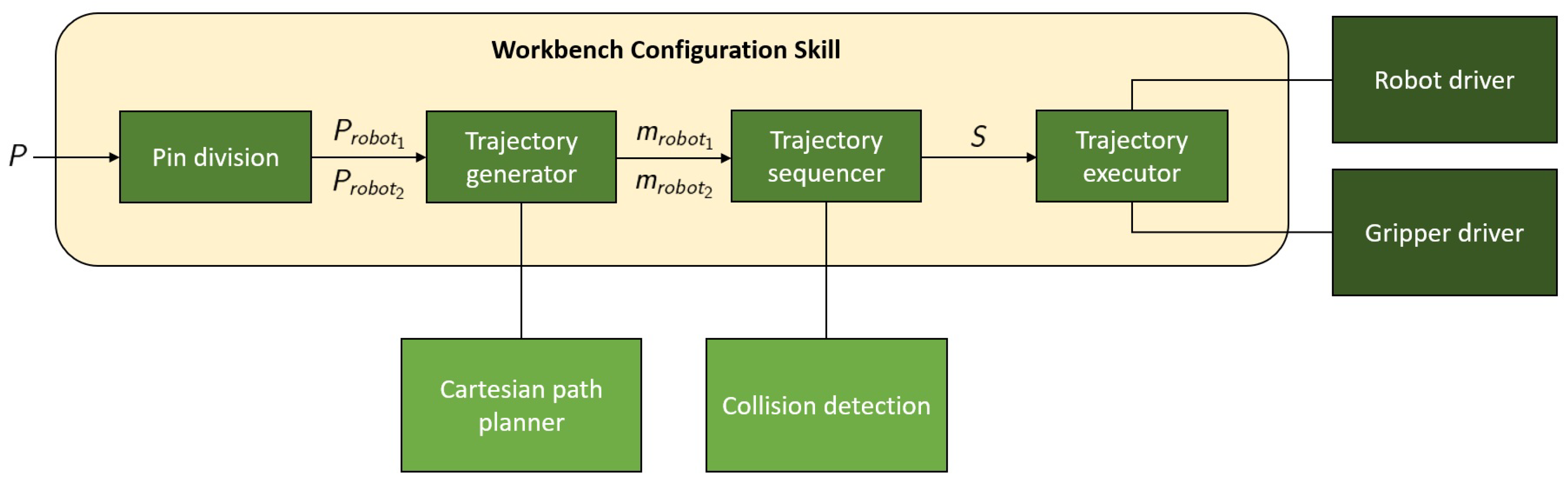
Specifically, the workbench configuration workflow, depicted in Figure 8, follows several key steps:

Figure 8.
Schema of the Workspace Configuration Skill.
- Initially, the Pin division step divides the pins to be placed, assigning them to the most appropriate robot arm.
- The second step is the Trajectory generation, where the module calculates the robot trajectories for the pin grasping and placing manoeuvres.
- In the fourth step the Trajectory sequencer defines the final trajectory sequence, checking if both robots can execute the movements in parallel to speed up the process.
- Finally, the Trajectory executor manages all these trajectories, operating both robots and grippers as defined in the plan.
The next lines provide further details on these four steps of the workflow and the calculation of the different modules.
Initially, the Pin division step divides the pin position set P into two disjoint sets and
where each pin of the set P is assigned to the nearest robot
based on the transformations between both robots and each pin position of the set P
The Trajectory generator uses these two subsets and to calculate the trajectories for the pin grasping and pin placement. Specifically, the maneuver m of grasping and positioning of the pin i for each robot’s subset and is defined by a set of trajectories
where and describe the trajectory from the safe pose to each robot’s pin feeder, and define the trajectory from the pin feeder to the pin placement pose on the CAD drawing and describe the trajectory back to the safe position from the pin pose on the CAD drawing.
All these manoeuvres represent a sequence of trajectories for each robot
where both and define a specific sequence S of robot trajectories for picking and placing pins.
Finally, the Trajectory sequencer checks if the defined trajectories can be executed in parallel without any collision or if they must be executed in a row to avoid any contact between the robots during the manoeuvres. Specifically, the collision check module will determine if maneuvers and can be executed simultaneously
or they must be placed one behind the other
in the complete manoeuvre sequence.
After the complete planning, the Trajectory executor receives the sequence S and executes all the planned trajectories in the provided order, moving the robots and managing the grippers as defined in the complete plan.
6.2.2. Routing Skill
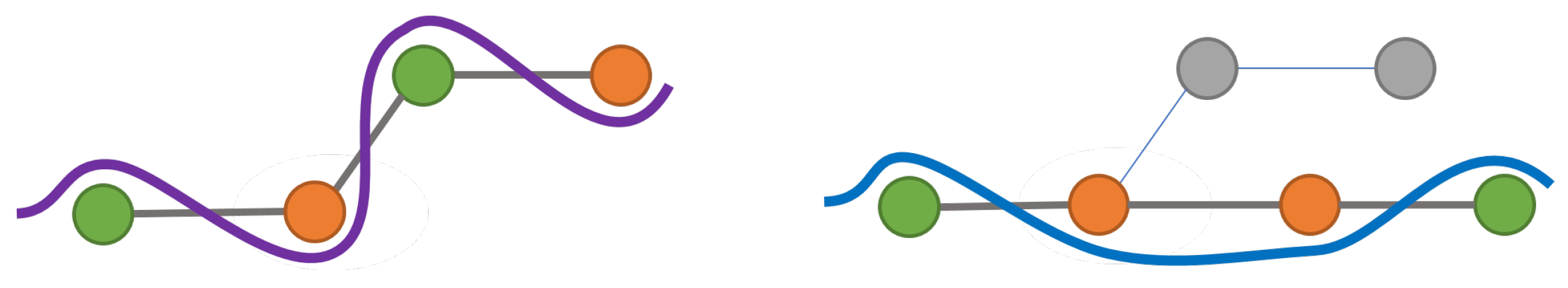
An important characteristic of the routing task is that operators follow a strategy in the process. During the routing, if curvature is found in the path, operators guide the wire through the external side of the pin. In the straight segments of the path, operators select arbitrarily the pin side. Additionally, at the endpoints, operators change the pin side to secure the wire. Therefore, a routing pathway will include some pins where operators are forced to select one specific side of the pins and some others where they can choose freely, as illustrated in the examples of Figure 9. The Routing Skill incorporates this strategy into the robots’ workflow.

Figure 9.
Diagram illustrating commonly found routing pathways.
Specifically, the Routing Skill is in charge of defining, planning, and executing the routing trajectory of a single cable. The module receives a set P of already positioned pins, as well as the path containing the set of pins that compose the routing pathway of cable i defined in the Offline Programming Framework.
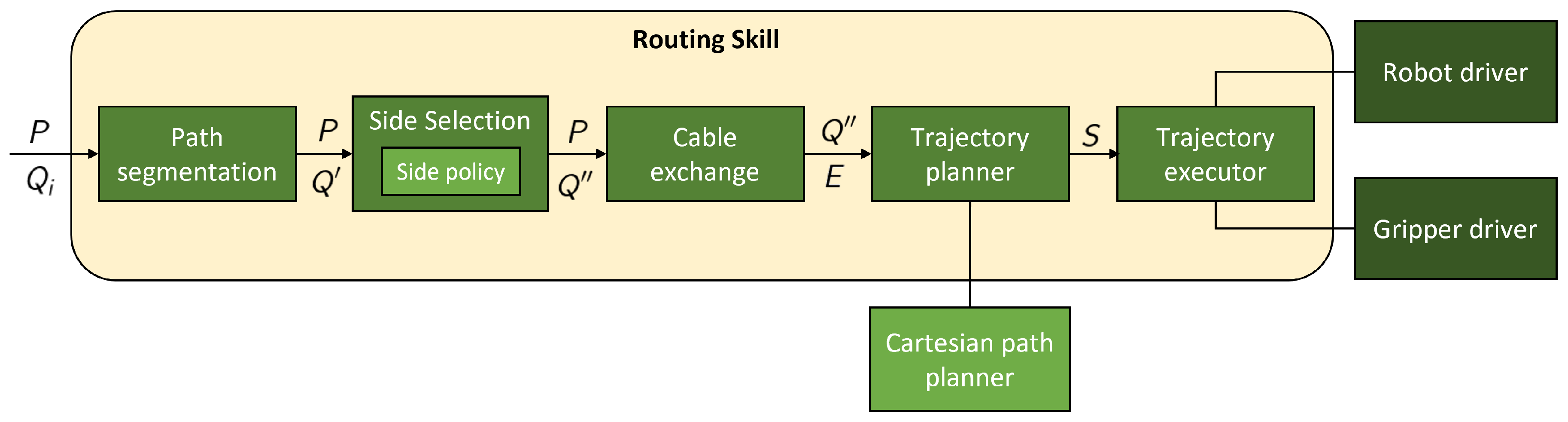
The routing workflow, depicted in Figure 10, follows several key steps:

Figure 10.
Schema of the Routing Skill.
- Initially, the path is subjected to a Path segmentation process, dividing the routing path into distinct segments assigned to the most appropriate robot arm.
- The second step is the Side selection, where the module defines the pin side that the path will follow to meet the routing strategy described above.
- The third step is the Cable exchange, where the most suitable cable exchange positions are estimated when both robots need to hand over the wire.
- In the fourth step the Trajectory planner calculates the robot trajectories of the previously calculated routing paths and cable exchange manoeuvres.
- Finally, the Trajectory executor manages all these trajectories, handling both robots and grippers as defined in the plan.
The next lines provide further information on these five steps of the workflow.
Initially, the Path segmentation step divides the complete pathway , assigning each segment to the most appropriate robot. Specifically, the routing pathway positions in are divided into N segments where
The module assigns each pin position to the nearest robot. In the case of a cable where all its pins reside within a single arm’s reach, the whole set of points is assigned to one segment . Otherwise, if a cable exchange is required between robots at any point in the complete path, that segment concludes. As a result, the cable’s path is divided into N segments where N can not be higher than the number of pins defining the routing path.
After the segmentation, the Side selection step modifies these original segments by including additional manoeuvres to ensure that the robots do not collide with the pins and follow the correct routing strategy. Therefore, this step modifies the segment set , generating a new segment set where the points are modified to comply with the routing strategy. Specifically, is defined as
where is a set of points of the same size as where the positions are modified to include the routing strategy manoeuvres.
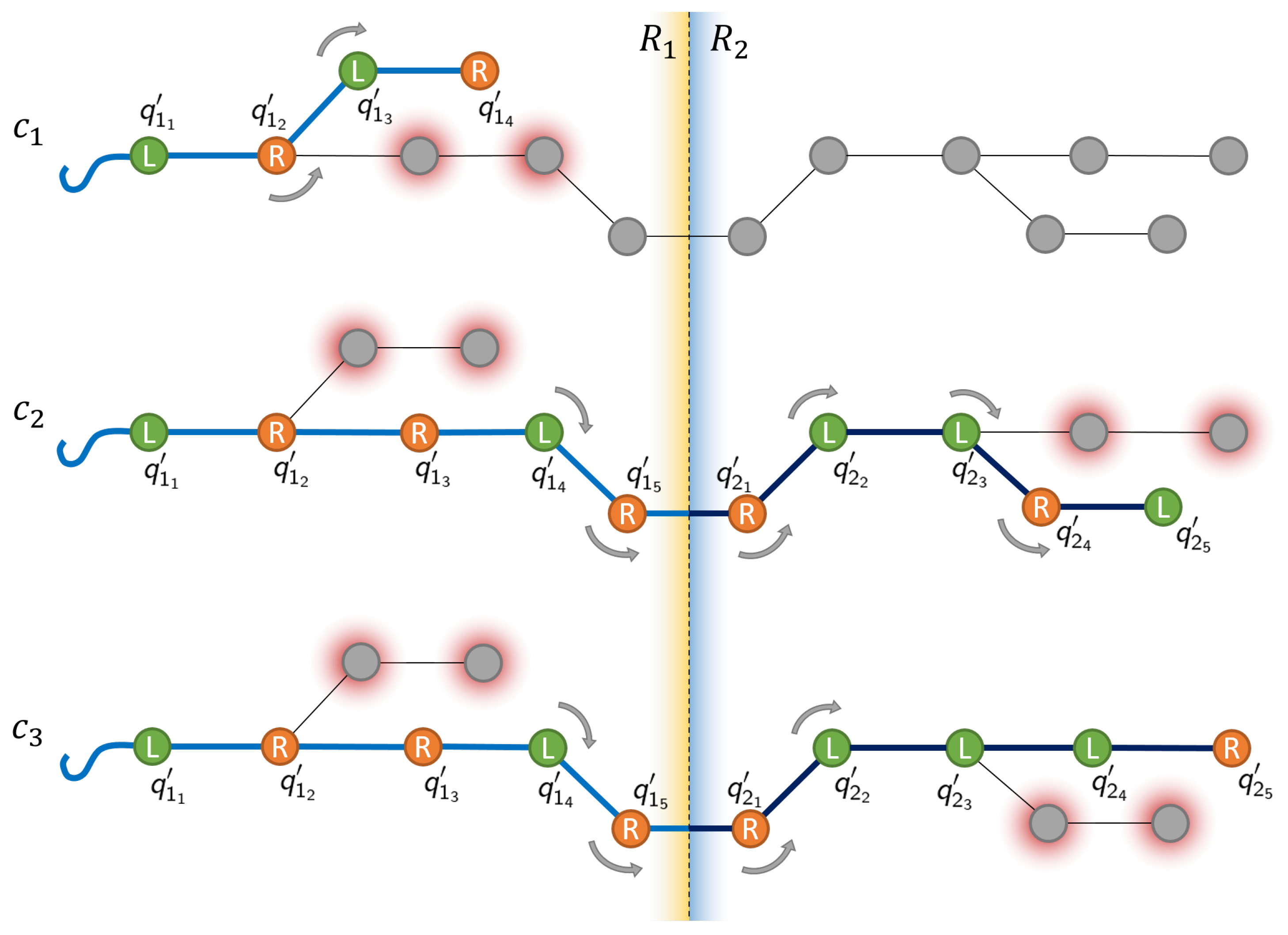
In the context of the routing pathway evaluation, Figure 11 provides a graphical representation of the routing strategy for three different cables, listed in descending order. The first cable, shown in the first row and labelled as , illustrates a case where a cable with a shorter path can be routed in its entirety by a single robotic arm. Conversely, the second and third cables, labelled as and respectively, present more complex routing cases, as their paths are divided into two segments by the line that intersects the workspace of robot and robot .
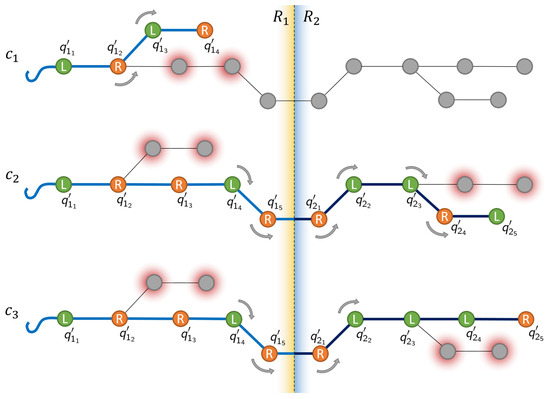
Figure 11.
Diagram of the cable routing process.
To achieve the required shape, the cable must pass through either the left or right side of the various pins on its path, denoted in Figure 11 by L or R respectively. Determining the proper go-through side for every pin is a key aspect of ensuring that the cable maintains the desired shape and avoids unexpected snaps or movements. Therefore, for any pin i, its side is expected as such
where represents the chosen side (left or right) for pin i.
A side convention is used, which establishes that the cable must pass through the external side of the pin at each bend or turning point. The external side policy ensures that the condition is met by calculating the curvature as
where corresponds to the Y component of the relative transformation between positions and , which is extracted from the homogeneous matrix calculated as
where and define the homogeneous transformation of path position and respectively.
Additionally, Figure 11 shows that for any pin located in straight sections of the path, there is no concern for curvature. Instead, the collision risk is evaluated. The collision policy assesses the chance of the robot, its gripper, or the grasped cable colliding with surrounding pins. The idea is to choose the side with lower collision risk (fewer pins in the area). This collision risk is estimated for every pin in the path, and for each side. For example, for a pin , the cost of the left side L is calculated by adding the cost of all pins located within that side, while the cost of each individual pin depends on its distance to the current pin where
Therefore, the total cost per side is defined as
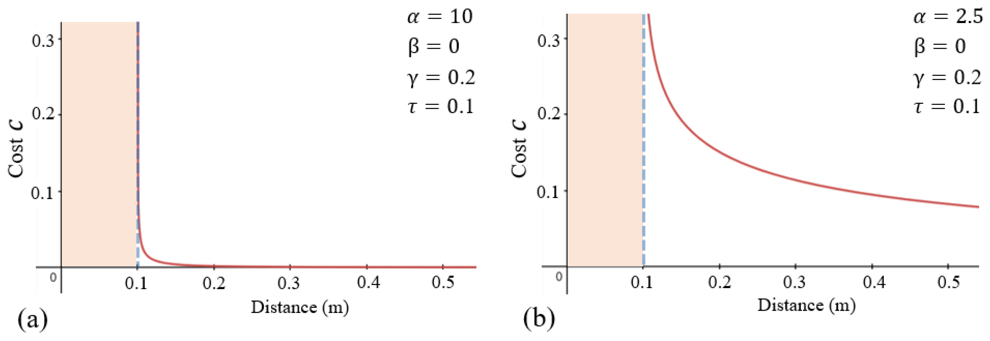
where parameters , , and the exponent control the shape of the decay curve, while and represent the total number of pins on the left side and on the right side, respectively. Additionally, stands for a previously defined safe threshold that can be adjusted. The decay curve and its shape determine the collision cost of any given pin based on its relative distance to the current pin . As shown in Figure 12, subfigure (a) depicts a cost curve that drastically decays past the safety threshold, reducing concern over pins outside the safety threshold. This curve is particularly well-suited for layouts with low concentrations of pins. On the contrary, subfigure (b) shows a gradually declining curve, which might be preferable for layouts with higher pin densities or more cramped conditions, as it allows further consideration over pins located beyond the threshold.
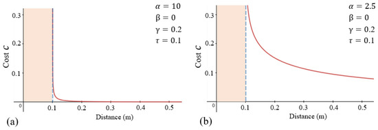
Figure 12.
Different cost curves used to determine the risk of pin collision based on relative distance.
Considering both the external side convention and, in the case of straight sections, the collision risk, the optimal go-through side is determined by the following conditions
where is used as a variable representing the curvature of the path.
The obtained side is then used to define the point through which the cable passes. It is defined as
where denotes the selected side sign. This value is used in
where represents the translation vector, defined by the side factor multiplied by the safety threshold . Therefore, following the routing strategy, a modified nominal point can be obtained from the original by means of
where the +homogeneous transformation is defined as
where represents the nominal pin position and depict the rotation matrix aligning the Z angle to face the next pin.
The third step of the routing workflow is the Cable exchange. Whenever a segment ends and another begins, a cable exchange should take place, an exchange where one robot hands over the cable to the other by carefully placing it on the table. To this end, a feasible position is required where the cable can be laid down and picked up by the second robot without disturbances. In the case of the end of the route, the exchange point is considered the final cable tip position.
Specifically, the Cable exchange module receives the set of segments and generates the new set E which includes the exchange points when required. Therefore, E is defined as
where each point defines the exchange point of segment j.
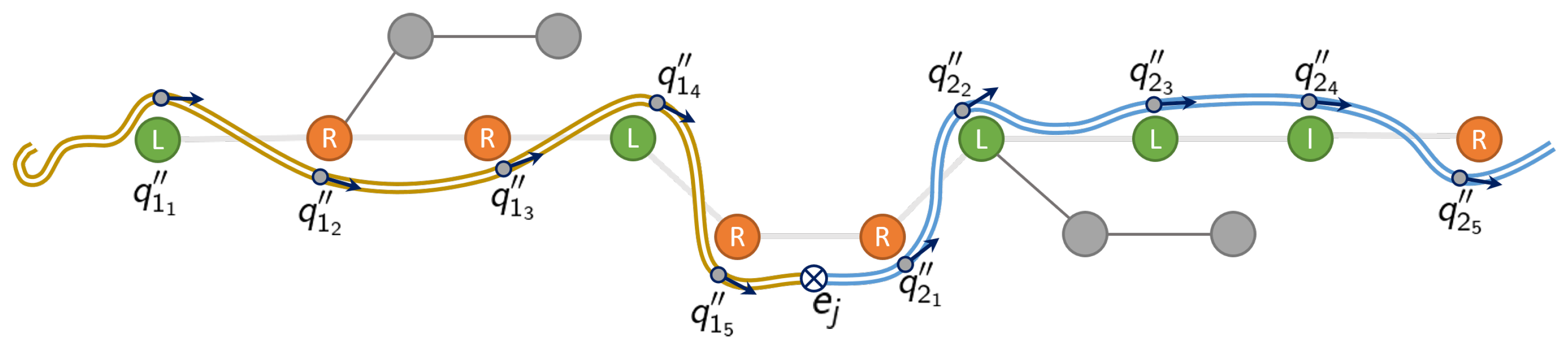
As shown in Figure 13, the ideal exchange point is located between segments, represented as ⨂. It is determined by the intersection of the intermediate plane between the two robots and the current path’s segment . The intersection point is defined as
where n is the normal vector of the intermediate plane, p represents the vector of the routing segment and is the point residing in the intermediate plane. After determining the ideal exchange point, to avoid any possible clash with nearby pins or already placed cables, a radiating search is performed to find the nearest valid place to rest the cable. This involves an iterative search process, which starts within the exchange point and radiates out checking nearby positions until a valid point is found.
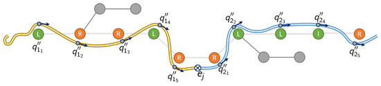
Figure 13.
Diagram showing the final routing pathway.
After determining the passing sides and exchange positions, the Trajectory planner uses the set of segments and the set of exchange points E to generate the routing robot trajectories S. The trajectory planning is also conducted by segments, each involving the planning of all manoeuvres: Cable grasp, routing across the pins while drawing the desired shape for each segment, and finally a retreat manoeuvre to ensure that the workspace is free for the other robot. Therefore, trajectory set S is defined by
where , , and define the grasping, routing and retreat maneuvers of segment j.
After the trajectory planning, the Trajectory executor receives the sequence S and executes all the planned trajectories, managing the robots and grippers as defined in the sequence.
7. Implementation
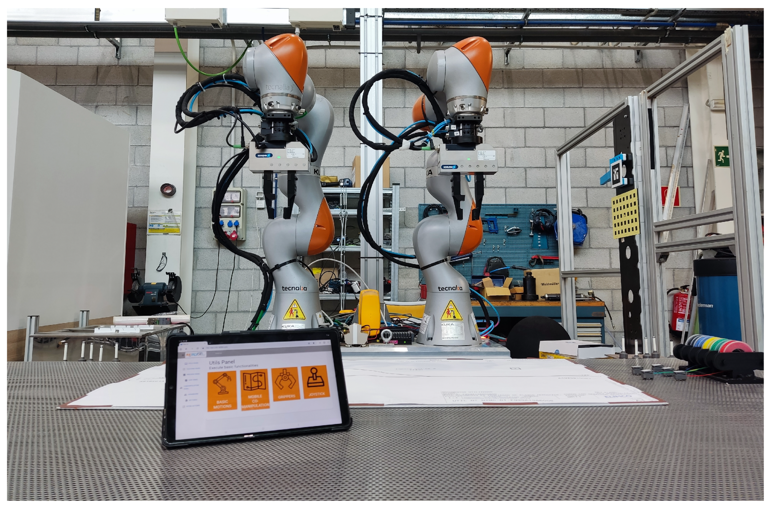
The presented solution has been implemented on a real setup to test and validate the approach. Specifically, the robotic setup is composed of two articulated robots in a dual-arm configuration and equipped with parallel grippers to manipulate both pins and wires. An important aspect of the setup is the capability to sense and control the applied forces and execute compliant movements to ensure the quality of the tasks, a feature that is not exploited in similar dual-arm and collaborative setups [17,18,19,24]. The implementation, illustrated in Figure 14, includes the following elements:
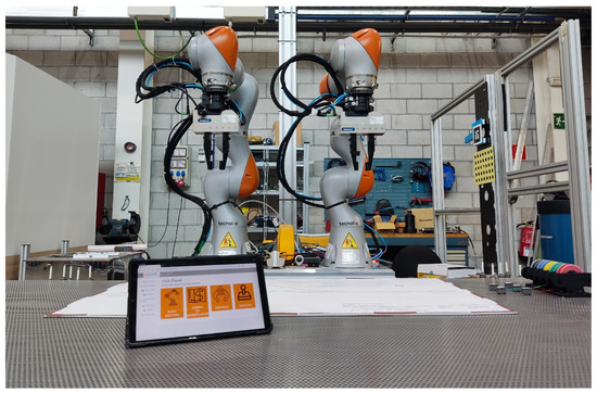
Figure 14.
Robotic setup for wire harness manufacturing.
- Two Kuka LBR iiwa 7 robots [33] (KUKA, Augsburg, Germany), 7-axis lightweight cobots equipped with torque sensors in each joint. Both arms are placed side-by-side in front of a workbench used for wire harness manufacturing. The compliant capabilities of the robots allow them to execute force-controlled movements; this capability ensures a safe execution of movements for pin placement and cable routing avoiding to damage the parts due to excessive forces.
- Each robot is equipped with a Schunk WSG50-110 gripper [34] (Weiss Robotics GmbH & Co. KG, Ludwigsburg, Germany), servo-electric grippers with a full stroke of 110 mm, and a gripping force of up to 80 N. Grippers include custom-designed fingers attached to them; specifically, the fingers have a planar shape with both sides covered by a thin foam to protect the cables and a vertical groove to ensure the grip of pins. The capability to set dynamically the desired gripping force, not present in the classical pneumatic grippers, is a critical aspect in the decision to include them in the setup due to the flexible nature of the grasped elements.
Additionally, the setup includes several components related to wire harness manufacturing:
- Workbench where all the elements of the wire harness are placed and managed.
- A metal sheet where operators place the CAD drawings.
- Pins of 60 mm in length and equipped with a magnetic base, which can be attached to the metal sheet of the drawing. Besides, two pin trays are placed near each robot to feed the system.
- A cable feeder consisting of 5 cable rolls placed on a side of the workbench. The tip of each cable includes a small clip with magnets to facilitate its grasping and ensure that it is correctly attached to the metal sheet.
All these robot hardware and manufacturing elements compose the implemented robotic setup. Additionally, the implementation also includes several features that take advantage of the robot hardware and improve the process:
- Compliant robot movements for both pin placing and cable routing. On the one hand, every pin and cable grasp and release movement includes compliance in the Z axis to avoid excessive forces that could damage the part. On the other hand, the routing paths include compliance in the X and Y axes to facilitate the routing and to alleviate the effects of possible entanglements.
- Variable gripping force of the grippers to ensure a suitable grasp for both pins and cables without any damage on the part.
All these hardware elements and implementation features constitute the proposed robotic setup. The setup has been tested with wires of a diameter between mm and mm and lengths between 1 m and 2 m.
8. Validation
A set of tests were defined to validate the proposed approach. Trying to cover the complete scope of the solution, the validation includes both the offline programming and real-time execution steps. On the one hand, the Offline Programming Framework aims to facilitate the generation of new robot programs by non-expert users. Therefore, an initial test evaluates the usability of the approach to generate programs for new wire harness references. On the other hand, the Real-Time Execution Framework has been evaluated utilizing different metrics to compare its performance with the manual work of operators.
The next paragraphs provide further details about the evaluation of both parts of the presented approach.
8.1. Offline Programming Framework Validation
The validation process aims to assess the Offline Programming Framework from the usability point of view. This framework allows extracting key information from the CAD drawings of the wire harnesses, generating XML files that are used afterwards by the Real-Time Execution Framework. Therefore, the validation measures how fast product designers can define the required cable and pin information on the CAD drawings of new wire harness references. This procedure replaces the robot program generation as the extracted geometrical information is directly used by the Real-Time Execution Framework to carry out the routing process.
The validation procedure involved 5 different subjects, referred to as S1 to S5 subsequently. Each of the subjects was asked to define the pin positions and cable routes for five wire harness references. To add variability to the process, three of the CAD files were 2D drawings and the other two were 3D drawings. Although the most common scenario is the use of 2D CAD files, in some specific cases customers only provide 3D drawings of the wire harness, and this validation tries to measure the impact of this change in the process. Table 1 summarizes the time required by each subject to define the pin positions and cable routes for each reference.

Table 1.
Offline programming time.
The obtained results show that subjects completed the task in a mean time of around five minutes and forty seconds on average, with a standard deviation of one minute and twenty seconds approximately. It is worth mentioning that subjects improved the time in each iteration with each CAD type (2D and 3D), pointing out that they got used quickly to the application and were able to carry out the task in less time. Another interesting point is that all subjects increased significantly process time when they shifted from 2D to 3D CAD models; as expected, moving around the drawing in 3D required more time than the equivalent task in a simpler 2D plane.
Regarding the time improvement, Table 2 summarizes how much subjects improved between the first and second wire harness reference for both 2D and 3D CAD types.
Table 2.
Improvement on offline programming time.
The results show that subjects improved their task time by 23% on average with a standard deviation of 10.7%. The improvement is higher for 2D CAD references; as subjects tried the application for the first time with a 2D reference, the main improvement occurred after the first contact with the application.
8.2. Real-Time Execution Framework Validation
The second phase of the validation aims to assess the performance of the Real-Time Execution Framework, comparing it with the manual work carried out by operators. As exposed in previous sections, the system deals with two tasks: Workbench configuration by placing the pins on the CAD drawing (task T1) and cable routing (task T2). Even so, the manual operation and the robotized solution have significant differences in the workflow:
- Manual operation: The operator configures the workbench (T1) and routes all the cables (T2). During both tasks, operators spend time checking the drawing information and cable/route tables to verify where each pin or cable should be placed.
- Robotized solution: The operator guides the robots to the calibration points of the drawing using a 6D joystick and launches the robot program. Afterwards, robots configure the workbench (T1) and route all the cables (T2). Operators only intervene in the calibration step, leaving the execution of tasks T1 and T2 to the robotic solution.
As the workflow changes from the manual to the robotized approach, a series of tests were designed to assess the presented work fairly. The next lines provide information about the manual operation time calculated as a baseline, as well as the tests carried out with the robotized solution.
8.2.1. Baseline
To compare both approaches fairly, a baseline is calculated with the time spent by operators on the tasks. The baseline calculation procedure involved 5 different subjects, referred to as S1 to S5 subsequently. Each of the subjects was asked to initially configure the workbench (T1) and route all the cables (T2) afterwards for two different wire harness references. For each reference, subjects were provided with some documentation with pin positioning guidelines and a table with the route for each cable. Each subject decided on its own how to manage the documentation, checking the provided data at any moment of the task without any restriction.
Table 3 contains the obtained baseline results, providing information about the time required for the workbench configuration and routing tasks, as well as the amount of time spent checking the documentation. The first column indicates the subject of the experiment. The next four columns provide information about the time spent on the task (placing pins), the time reviewing the documentation, the total time, and the efficiency of the task (percentage of time spent placing pins). The final four columns give information about the time spent in routing, the documentation reviewing time, the total time, and the efficiency of the cable routing operation.
Table 3.
Baseline with operator task time for Real-time Execution Framework validation.
The obtained results show that subjects spent a mean time of 57 and 51 configuring the workbench in each wire harness reference, while the routing took and . These values will be used as a baseline for the validation process. Additionally, the efficiency of the tasks is between 40% and 43%, which points out that subjects spend more than half of their time revising the documentation (around 30 for workbench configuration a more than a minute for routing).
An interesting point is that subject S5 made a mistake routing reference 1, which caused a noticeable time loss to correct the error. Due to this error, this same subject also spent a large amount of time revising the instructions during the routing of reference 2.
8.2.2. Robotized Solution
As described previously, the robotized solution modifies slightly the manual operation workflow. In the new paradigm, operators only need to guide both arms to the calibration points, leaving the workbench configuration and routing task to the dual-arm robotic system, as shown in Figure 15. Specifically, the new workflow includes the following steps:
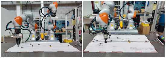
Figure 15.
Robot placing pins and routing.
- Calibration: The operator guides both robots to the calibration points using a 6D joystick (implemented as two twist controllers on the robotic system). Once the calibration points are reached, operators launch the application, which starts executing the calibration procedure of the CAD Information Manager module. The calibration step mainly lasts the time spent by the operator guiding the robot to the defined points as the final optimization procedure requires between 50–100 ms.
- Workbench configuration: The Worbench Configuration Skill executes the pin placing operation using the CAD data provided by the CAD Information Manager module. Operators do not intervene in this step.
- Routing: The Routing Skill places all the cables of the list using the CAD data provided by the CAD Information Manager module. Operators do not intervene in this step.
The validation process of the robotized approach involved 5 different subjects, referred to as S1 to S5 subsequently. Initially, each of the subjects was asked to guide both arms to the calibration points of the drawing and launch the application. Afterwards, the robotic system executes both the workbench configuration and routing operations autonomously. The procedure was repeated for the previously used two wire harness references, involving subjects in two different tests.
Table 4 summarizes the obtained results. The first column provides information about the experiment subject. The second column offers information about the time spent by the subjects guiding the robots to the calibration points (joint human-robot task). Finally, columns three and four detail the time spent by the robot (without operator intervention) in the workbench configuration and cable routing subsequently.
Table 4.
Task times of robotized solution for the Real-time Execution Framework validation.
The obtained results show that subjects spent a mean time of 57 and 48 in the calibration step, improving the results in the second reference due to the familiarization with the calibration procedure. Regarding the robotized task, the workbench configuration required and while the routing process required and . In both cases, the time required by the robots for each task in both wire harness references is very similar, with a very low standard deviation. Additionally, the robotized solution obtained a success rate of for both pin placement and cable routing operations.
8.2.3. Comparison
Once the baseline and robotized solution’s results are obtained, they are compared to assess the performance of the proposed approach. Initially, the task times of the manual and robotized operations are compared in Table 5. The first column of the table contains the operation type. Columns two to four contain the times spent in the calibration, workbench configuration, and routing steps subsequently.
Table 5.
Comparison of the manual and robotized solution’s task times for the Real-time Execution Framework validation.
Results show that for both tasks, workbench configuration and routing, the manual solution is faster than the robotized operation, specifically around 50% faster in the second reference. Operators can carry out the pin pick and place operations and the routing of cables faster than the robotic system, especially the routing as the cable exchange between robots penalizes highly the robotized approach (around 20 s per exchange).
Besides, the time spent by operators and robots is also compared in Table 6 to complete the analysis of the task times. The first column provides information about the operation type. The second column indicates the time spent by the operator performing the calibration, workbench configuration, and routing, while the third column shows the time spent by the robots. The fourth column indicates the total time, adding up the manual and robotic work. Finally, the fifth column shows the portion of task time spent reviewing the documentation.
Table 6.
Comparison of operator and robot times of the Real-time Execution Framework validation.
On the one hand, the total time in manual operation is 36.4% and 56.1% faster for each wire harness reference. On the other hand, the comparison points out that even if the total task time is greater in the robotized approach, the operator time is significantly reduced at 72.6% and 70.7% and obviously the idle times where operators review the documentation are reduced to zero.
The obtained results show the feasibility of the approach; even if the complete task time is greater in the robotized solution, the human operator time is significantly reduced. Besides, the documentation checking time is also removed from the process, which might prove advantageous as the complexity of the wiring harness increases, leading to further time savings not only in human labour but also in the total production time. avoiding errors in the interpretation of the cable and route data.
8.2.4. Scalability
An important aspect of the robotized approach is scalability. In the robotized solution, the operator only takes part in the calibration process, which lasts around 1 min. If we consider the obtained baseline information, routing a single cable involves around 25, including the documentation check and the task itself. Therefore, a 5-cable wire harness would involve around 2 min of routing, while a 25-wire harness would increase the time to 10 min. Additionally, it is expected that operators would spend more time revising documentation in this last case due to the large amount of information on the documents, increasing the idle times, the routing time per cable, as well as the possible human errors in the information interpretation. Therefore, the application of the robotized paradigm gains strength in complex scenarios with a large number of cables.
9. Conclusions and Future Work
The presented work proposes a CAD-based robot programming solution for wire harness manufacturing in the aeronautic sector, an industry with completely manual manufacturing. One of the main drawbacks of process automation in this industry is the large number of references and the low size of the batches. Additionally, due to the complexity of the task, operators spend a large amount of time revising the documentation as they are not familiar with the specific features of each reference.
Therefore, the proposed solution tackles two of the main issues of the scenario, the facility to program new references and the capability to adapt the robot trajectories to the features of each wire harness reference. The paper focuses on the initial steps of the manufacturing process, the workbench preparation where operators place pins to facilitate the cable routing, and the cable routing itself.
Specifically, a two-phase architecture is proposed: Initially, the Offline Programming Framework allows defining key elements of the process like the pin positions and cable routes based on the CAD drawings of the references; afterwards, the Real-Time Execution Framework manages the CAD information and generates the robot trajectories in real-time.
The proposed solution has been implemented in a real setup with a dual-arm robot. Besides, a validation process has been carried out to assess the performance of the approach. The obtained results show the feasibility of the solution, implementing a system able to extract key information from the CAD models of the wire harnesses and adapt the trajectories of the workbench configuration and routing based on this information. Even so, task times of the robotized solution are slower than the manual work although the time required by the operator overall is far lower, allowing to employ operators’ time in tasks with higher added value.
For future steps, the first issue is to parallelize the robots’ movements as much as possible to speed up the task. Even so, this parallelization would become the planning in a huge optimization problem as both robots should be able to perform different wire routings in parallel, requiring the analysis of a large number of possible solutions. Additionally, another important issue is to evolve the current hardware and physical elements of the cell to simplify some tasks for the robots as the developed setup imitates how manual operations are made by humans, making the tasks more complex and slower. An evolution of the setup would also speed up and stabilize the robotized process, making it more efficient and profitable. This could be achieved, for instance, by designing more complex grippers or integrating vision-based calibrations of the wire harness sketch. Such integration would reduce the need for manual intervention, consequently reducing calibration time. Besides, the use of active cable dispensers would allow the management of larger and thicker wires, reducing the friction between the cable and the elements of the workbench and assisting the routing. Finally, the current routing execution relies on the compliant movements to ensure its success although it could be improved by adding a more complex force-based controller that reacts to excessive forces caused by entanglements.
Author Contributions
Conceptualization, J.G.H. and A.I.; methodology, J.G.H. and A.I.; software, J.G.H., M.O.d.Z. and A.I.; validation, J.G.H. and A.I.; formal analysis, A.I.; investigation, J.G.H., M.O.d.Z. and A.I.; resources, J.G.H. and M.O.d.Z.; data curation, A.I.; writing—original draft preparation, A.I.; writing—review and editing, J.G.H. and A.I.; visualization, J.G.H.; supervision, M.O.d.Z. All authors have read and agreed to the published version of the manuscript.
Funding
This work has received funding from the European Union Horizon 2020 research and innovation programme as part of the project REMODEL under grant agreement No. 870133.
Data Availability Statement
Experiment data is available at https://doi.org/10.5281/zenodo.8287698 (accessed on 27 August 2023).
Conflicts of Interest
The authors declare no conflict of interest.
References
- Aguirre, E.; Raucent, B. Performances of wire harness assembly systems. In Proceedings of the 1994 IEEE International Symposium on Industrial Electronics (ISIE’94), Santiago, Chile, 25–27 May 1994; pp. 292–297. [Google Scholar]
- Aguirre, E.; Raucent, B. Economic comparison of wire harness assembly systems. J. Manuf. Syst. 1994, 13, 276–288. [Google Scholar] [CrossRef]
- Neto, P.; Pires, J.N.; Moreira, A.P. CAD-based off-line robot programming. In Proceedings of the 2010 IEEE Conference on Robotics, Automation and Mechatronics, Singapore, 28–30 June 2010; pp. 516–521. [Google Scholar]
- Neto, P.; Mendes, N. Direct off-line robot programming via a common CAD package. Robot. Auton. Syst. 2013, 61, 896–910. [Google Scholar] [CrossRef]
- Foit, K.; Ćwikła, G. The CAD drawing as a source of data for robot programming purposes—A review. MATEC Web Conf. 2017, 94, 05002. [Google Scholar] [CrossRef]
- Norberto Pires, J.; Godinho, T.; Ferreira, P. CAD interface for automatic robot welding programming. Ind. Robot. Int. J. 2004, 31, 71–76. [Google Scholar] [CrossRef]
- Larkin, N.; Short, A.; Pan, Z.; Van Duin, S. Automatic program generation for welding robots from CAD. In Proceedings of the 2016 IEEE International Conference on Advanced Intelligent Mechatronics (AIM), Banff, AB, Canada, 12–15 July 2016; pp. 560–565. [Google Scholar]
- Ferreira, L.A.; Figueira, Y.L.; Iglesias, I.F.; Souto, M.Á. Offline CAD-based robot programming and welding parametrization of a flexible and adaptive robotic cell using enriched CAD/CAM system for shipbuilding. Procedia Manuf. 2017, 11, 215–223. [Google Scholar] [CrossRef]
- Klein, A. CAD-based off-line programming of painting robots. Robotica 1987, 5, 267–271. [Google Scholar] [CrossRef]
- Kim, J. CAD-based automated robot programming in adhesive spray systems for shoe outsoles and uppers. J. Robot. Syst. 2004, 21, 625–634. [Google Scholar] [CrossRef]
- Deng, S.; Cai, Z.; Fang, D.; Liao, H.; Montavon, G. Application of robot offline programming in thermal spraying. Surf. Coat. Technol. 2012, 206, 3875–3882. [Google Scholar] [CrossRef]
- Bi, Z.M.; Lang, S.Y. A framework for CAD-and sensor-based robotic coating automation. IEEE Trans. Ind. Inform. 2007, 3, 84–91. [Google Scholar] [CrossRef]
- Neto, P.; Mendes, N.; Araújo, R.; Norberto Pires, J.; Paulo Moreira, A. High-level robot programming based on CAD: Dealing with unpredictable environments. Ind. Robot. Int. J. 2012, 39, 294–303. [Google Scholar] [CrossRef]
- Warnecke, H.; Walther, J.; Schlaich, G. Flexible automated wiring harness assembly. In Toward the Factory of the Future, Proceedings of the 8th International Conference on Production Research and 5th Working Conference of the Fraunhofer-Institute for Industrial Engineering (FHG-IAO) at University of Stuttgart, Stuttgart, Germany, 20–22 August 1985; Springer: Berlin/Heidelberg, Germany, 1985; pp. 453–460. [Google Scholar]
- Jiang, X.; Koo, K.M.; Kikuchi, K.; Konno, A.; Uchiyama, M. Robotized assembly of a wire harness in a car production line. Adv. Robot. 2011, 25, 473–489. [Google Scholar] [CrossRef]
- Palomba, I.; Gualtieri, L.; Rojas, R.; Rauch, E.; Vidoni, R.; Ghedin, A. Mechatronic re-design of a manual assembly workstation into a collaborative one for wire harness assemblies. Robotics 2021, 10, 43. [Google Scholar] [CrossRef]
- Navas-Reascos, G.E.; Romero, D.; Rodriguez, C.A.; Guedea, F.; Stahre, J. Wire harness assembly process supported by a collaborative robot: A case study focus on ergonomics. Robotics 2022, 11, 131. [Google Scholar] [CrossRef]
- Zhang, X.; Domae, Y.; Wan, W.; Harada, K. A Closed-Loop Bin Picking System for Entangled Wire Harnesses using Bimanual and Dynamic Manipulation. arXiv 2023, arXiv:2306.14595. [Google Scholar]
- Lv, N.; Liu, J.; Jia, Y. Dynamic modeling and control of deformable linear objects for single-arm and dual-arm robot manipulations. IEEE Trans. Robot. 2022, 38, 2341–2353. [Google Scholar] [CrossRef]
- Nguyen, H.G.; Habiboglu, R.; Franke, J. Enabling deep learning using synthetic data: A case study for the automotive wiring harness manufacturing. Procedia CIRP 2022, 107, 1263–1268. [Google Scholar] [CrossRef]
- Huang, X.; Chen, D.; Guo, Y.; Jiang, X.; Liu, Y. Untangling Multiple Deformable Linear Objects in Unknown Quantities with Complex Backgrounds. IEEE Trans. Autom. Sci. Eng. 2023; early access. [Google Scholar] [CrossRef]
- Caporali, A.; Zanella, R.; Greogrio, D.D.; Palli, G. Ariadne+: Deep Learning–Based Augmented Framework for the Instance Segmentation of Wires. IEEE Trans. Ind. Inform. 2022, 18, 8607–8617. [Google Scholar] [CrossRef]
- Žagar, B.L.; Caporali, A.; Szymko, A.; Kicki, P.; Walas, K.; Palli, G.; Knoll, A.C. Copy and Paste Augmentation for Deformable Wiring Harness Bags Segmentation. In Proceedings of the 2023 IEEE/ASME International Conference on Advanced Intelligent Mechatronics (AIM), Seattle, WA, USA, 28–30 June 2023; pp. 721–726. [Google Scholar]
- Tunstel, E.; Dani, A.; Martinez, C.; Blakeslee, B.; Mendoza, J.; Saltus, R.; Trombetta, D.; Rotithor, G.; Fuhlbrigge, T.; Lasko, D.; et al. Robotic wire pinning for wire harness assembly automation. In Proceedings of the 2020 IEEE/ASME International Conference on Advanced Intelligent Mechatronics (AIM), Boston, MA, USA, 6–9 July 2020; pp. 1208–1215. [Google Scholar]
- Guo, J.; Zhang, J.; Wu, D.; Gai, Y.; Chen, K. An algorithm based on bidirectional searching and geometric constrained sampling for automatic manipulation planning in aircraft cable assembly. J. Manuf. Syst. 2020, 57, 158–168. [Google Scholar] [CrossRef]
- Morrow, J.D.; Khosla, P.K. Manipulation task primitives for composing robot skills. In Proceedings of the International Conference on Robotics and Automation, Albuquerque, NM, USA, 25 April 1997; Volume 4, pp. 3354–3359. [Google Scholar]
- Bøgh, S.; Nielsen, O.S.; Pedersen, M.R.; Krüger, V.; Madsen, O. Does your robot have skills? In Proceedings of the 43rd International Symposium on Robotics, Taipei, Taiwan, 29–31 August 2012. [Google Scholar]
- Pedersen, M.R.; Nalpantidis, L.; Andersen, R.S.; Schou, C.; Bøgh, S.; Krüger, V.; Madsen, O. Robot skills for manufacturing: From concept to industrial deployment. Robot. Comput.-Integr. Manuf. 2016, 37, 282–291. [Google Scholar] [CrossRef]
- Agarwal, S.; Mierle, K.; The Ceres Solver Team. Ceres Solver. 2022. Available online: https://github.com/ceres-solver/ceres-solver (accessed on 27 August 2023).
- Descartes: Cartesian Path Planner. Available online: http://wiki.ros.org/descartes (accessed on 27 August 2023).
- Pan, J.; Chitta, S.; Manocha, D. FCL: A general purpose library for collision and proximity queries. In Proceedings of the 2012 IEEE International Conference on Robotics and Automation, Saint Paul, MN, USA, 14–18 May 2012; pp. 3859–3866. [Google Scholar] [CrossRef]
- Chitta, S.; Sucan, I.; Cousins, S. MoveIt! [ROS Topics]. IEEE Robot. Autom. Mag. 2012, 19, 18–19. [Google Scholar] [CrossRef]
- Kuka LBR iiwa. Available online: https://www.kuka.com/en-us/products/robotics-systems/industrial-robots/lbr-iiwa (accessed on 27 August 2023).
- Schunk WSG50 Grippers. Available online: https://weiss-robotics.com/servo-electric/wsg-series/product/wsg-series/ (accessed on 27 August 2023).


Disclaimer/Publisher’s Note: The statements, opinions and data contained in all publications are solely those of the individual author(s) and contributor(s) and not of MDPI and/or the editor(s). MDPI and/or the editor(s) disclaim responsibility for any injury to people or property resulting from any ideas, methods, instructions or products referred to in the content. |
© 2023 by the authors. Licensee MDPI, Basel, Switzerland. This article is an open access article distributed under the terms and conditions of the Creative Commons Attribution (CC BY) license (https://creativecommons.org/licenses/by/4.0/).