Abstract
In recent times, the soft robotics field has been attracting significant research focus owing to its high level of manipulation capabilities unlike traditional rigid robots, which gives room for increasing use in other areas. However, compared to traditional rigid gripper robots, being capable of controlling/obtaining overall body stiffness when required is yet to be further explored since soft gripper robots have inherently less-rigid properties. Unlike previous designs with very complex variable-stiffness systems, this paper demonstrates a soft gripper design with minimum system complexity while being capable of varying the stiffness of a continuum soft robotic actuator and proves to have potential applications in gripping objects of various shapes, weights, and sizes. The soft gripper actuator comprises two separate mechanisms: the pneumatic mechanism for bending control and the mechanical structure for stiffness variation by pulling tendons using stepper motors which compresses the actuator, thereby changing the overall stiffness. The pneumatic mechanism was first fabricated and then embedded into another silicon layer during which it was also merged with the mechanical structure for stiffness control. By first pneumatically actuating the actuator which causes bending and then pulling the tendons, we found out that the actuator stiffness value can be increased up to 145% its initial value, and the gripper can grasp and lift a weight of up to 2.075 kg.
1. Introduction
Soft robotics is an emerging field of robotics that aims to develop robots made of soft and flexible materials, such as elastomers, polymers, and hydrogels, which can bend, stretch, and deform like natural organisms. The concept of softs robotics is inspired by the natural world, where soft-bodied organisms, such as octopus, caterpillars, and jellyfish have the ability to adapt to various environments and perform complex tasks. The development of soft robotics requires a multidisciplinary approach, with contributions from fields such as materials science, mechanical engineering, and biology.
One area where soft robots can have a significant impact is in healthcare. They can be used in minimally invasive surgeries, such as those involving the heart or brain, where rigid robots cannot safely access. Additionally, they are used in rehabilitation and prosthetics to provide safe and effective support for patients [1]. They can also be used in surgical training and education [2]. They also have potential uses in manufacturing, where they can be used for assembly and manipulation of delicate objects, such as electronic components and food items. Soft robots are also used for inspection and quality control in manufacturing processes [3]. They can be used for exploration in challenging environments, such as underwater or space environments, where rigid robots may not be suitable [4]. Researchers are developing new materials that are capable of responding to stimuli such as heat, light, or electricity, allowing soft robots to perform a wider range of tasks [5]. Soft grippers can be made using a variety of materials, including silicone, hydrogels, and polymers [6]. The Harvard Wyss Institute has developed an octopus-inspired soft robot that is capable of crawling, swimming, and grasping objects [7]. Shepherd et al., Xu et al., and Calderón et al., have developed a worm-inspired soft robot that can move through tight spaces and deform its shape to fit its surroundings [8,9,10]. Soft grippers can be used for handling and manipulating delicate objects, such as electronic components or food items, without damaging them [11]. They can also be used for packaging and assembly, where they can provide a gentle but secure grip on items [12]. Another domain of soft robotics are wearable robots. Wearable soft robots can be categorized into two main types: active and passive. Active wearable soft robots incorporate sensors and actuators to provide assistance to the wearer’s movements, while passive wearable soft robots rely on their material properties to provide structural support to the wearer. Passive wearable soft robots are particularly useful in rehabilitation applications, where they can be used to provide support and reduce the risk of injury during physical therapy [1]. Active wearable soft robots, on the other hand, have applications in areas such as assistive technology, military, and entertainment. In the military, wearable soft robots can be used for load carriage and to enhance the physical capabilities of soldiers [13]. In entertainment, wearable soft robots can be used to create immersive experiences, such as haptic feedback for virtual reality applications [14]. Researchers at Harvard University have developed a soft exosuit that can assist the wearer’s gait [15].
Several research studies have been conducted to investigate the performance of variable-stiffness pneumatic soft grippers. For instance, a pneumatic soft gripper that uses a composite membrane to achieve variable stiffness and demonstrates its ability to grasp and manipulate objects of different shapes and sizes [16]. Another study proposed a modular soft gripper that can achieve variable stiffness by adjusting the pressure of the air chambers, and showed that it can handle delicate objects without causing damage [17]. Also, another work demonstrated the use of a soft gripper with variable stiffness in a food packaging application [18], while another proposed the use of such grippers in a robotic hand for prosthetic application [19]. Furthermore, another way of being capable of changing the stiffness of a robotic gripper is by means of cables or tendons. These grippers are then actuated by cables or tendons, which transmit forces from an external source, such as a motor or an air compressor, the gripper’s fingers. For example, a soft gripper that employed shape memory alloy springs to control stiffness was designed [20], while another developed a hybrid soft gripper that combined pneumatic and cable-driven actuators for variable-stiffness control [21]. A variable-stiffness soft gripper mechanism consisting of a rigid segment and a compliant segment such that when the soft body surrounded by rigid bodies is axially compressed by pulling tendons when clamped, it leads to a stiffness increase in the gripper [22]. Also, other researchers developed a closed-loop control system that used electromyography signals to control the gripper’s stiffness and grasp force [23]. Furthermore, Yilun Sun et al. developed a Lightweight Robotic Gripper (LARG) With 3D Topology Optimized Adaptive Fingers whereby using an additional spring in the design problem, they achieved an adaptive grasping function [24]. Dalibor Petković et al. developed a new type of passively adaptive compliant gripper where an underactuated mechanism uses fewer active inputs than the number of degrees of freedom of the gripper mechanism to drive the open and close motion of the gripper [25]. Also, Zebing Mao et al. developed a fluidic rolling robot using voltage-driven oscillating liquid [26]. Yanhong Peng et al. modeled a fabric-type actuator using point clouds via deep learning [27].
In recent years, there have been several studies on the development and applications of tendon-driven variable-stiffness soft grippers (TVSSG). One such study introduced a tendon-driven soft gripper that achieved variable stiffness by adjusting the tension of tendons [28]. The gripper was able to grasp objects of different shapes and sizes with different levels of stiffness. Another study proposed a TVSSG design that uses a single pneumatic actuator to drive multiple fingers with different stiffness levels. The stiffness of each finger is controlled by a tendon mechanism, which facilitates independent adjustments of the grip force and compliance. The authors reported successful grasping of objects with different shapes and sizes, demonstrating the potential of TVSSGs for versatile grasping tasks [29]. These grippers have complex variable-stiffness mechanisms.
The goal of this research is to explore the development and application of a minimum variable-stiffness system complexity, while still being capable of achieving high performance of a tendon-driven variable-stiffness pneumatic soft gripper robot. This type of gripper is designed to provide a high degree of dexterity and flexibility in grasping and manipulating delicate objects. In this paper, three soft variable-stiffness pneumatic actuators were made and then combined to form a variable-stiffness soft pneumatic gripper. A single variable-stiffness pneumatic soft actuator comprises two separate mechanisms: the pneumatic mechanism for bending control and the mechanical structure for stiffness variation by pulling tendons. For bending control, a soft body part consisting of two air chambers was manufactured and then embedded into another soft body part to form the overall actuator. Applying pneumatic pressure into the two chambers causes the soft actuator to bend. The amount of actuator bending depends on the amount of pneumatic air supplied into the air chambers. The variable-stiffness structure was manufactured by connecting three tendons to a rigid part before embedding it into the soft pneumatic part. To vary the stiffness of the soft actuator, when the tendons attached at the end of the rigid part, embedded into the soft part are pulled, the soft body compresses, thereby changing the stiffness across the overall length of the soft actuator. That is, when the soft pneumatic actuator is compressed, there is a non-linear increase in stiffness along the entire soft actuator. The amount of stiffness change depends on the extent to which the tendons are pulled. The three tendons in the soft actuator were attached to pulleys mounted on the shaft of stepper motors. The soft bodies were manufactured with EcoFlex 0050, which is a type of Silicon from Smooth-On Inc., Macungie, PA, USA. The rigid part to which the tendons are connected to was manufactured from PLA material via 3D printing. The material of the tendons is AISI 304 steel. The tendons were enclosed in a tendon hose which prevents the tendons from having direct contact with the soft silicon body, thereby limiting friction to avoid abrasion or wear of the silicon body as a result of continuously pulling the tendons. A strain-limiting layer made of fiber material was also attached to the first silicon body before embedding into the second silicon soft body. This helps in limiting lateral bending and enhances vertical bending. It also helps in limiting overstretching of the actuator when pneumatic pressure is supplied into its air chambers, which may cause failure of the soft actuator. During the initial designs of the actuator, the actuator length was made long but led to a buckling motion during the pulling process of the tendons. To solve this problem, the actuator’s length was reduced. The soft actuators were designed and manufactured to assume a rectangular shape. By combining three of the actuators to form a robotic gripper, grasping experiments on objects of different shapes, sizes, and weights were successfully performed, and as a result of pulling tendons, which increases the actuator’s stiffness, the gripper was capable of grasping and lifting various objects of different shapes, sizes, and weights. Furthermore, a variable-stiffness experiment was conducted on a single soft actuator using the Universal Testing Machine (UTM), during which the actuator’s stiffness values at different stiffness states were recorded. The dynamics of the soft actuator was modeled using Pseudo-Rigid Body Modeling (PRBM) technique, which validated the experimental results. The soft actuator and the overall gripper system CAD design are, respectively, shown in Figure 1 and Figure 2 below.
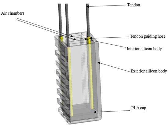
Figure 1.
Variable-stiffness pneumatic soft actuator.
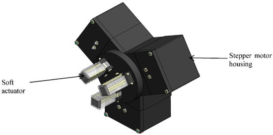
Figure 2.
Gripper mechanism CAD design.
2. Materials and Methods
The variable-stiffness mechanism was designed and manufactured to have a minimum system complexity, while still being capable of effectively varying the stiffness of the soft pneumatic gripper. It consists of three tendons manufactured from AISI 304 steel material which are fixed on one side using fishing tackles, to a rigid part manufactured from PLA material via 3D printing and the other side fixed to stepper motor pulleys. The rigid PLA part to which the tendons are fixed has a length of 20 mm, width of 4 mm, and height of 7 mm. The rigid PLA part was designed and manufactured to assume the shape of the soft actuator to ease the embedding process into the soft silicon body. A tendon guidance hose was also added to the mechanical structure to limit friction between the tendons and the soft silicon body, during continuous tendon pulling which leads to wearing out of the silicon body of the actuator. The CAD design and fabricated mechanism can be seen in Figure 3 below.
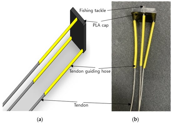
Figure 3.
Design and fabrication of variable-stiffness mechanical structure. (a) Mechanical structure CAD design and (b) fabricated mechanical structure.
The soft actuator was designed and fabricated to generate bending motion when pneumatic pressure is supplied into its air chambers. By increasing the pneumatic pressure in the air chambers increases the bending, until it reaches its bending limit. There are two soft body layers that comprise the pneumatic soft actuator: the interior pneumatic soft body and the exterior soft body. Both of these soft body layers are manufactured from EcoFlex 0050, a silicon material from Smooths-On. The two designs were completed and manufactured separately and then combined to form the soft actuator. To manufacture the soft pneumatic actuator, the interior pneumatic soft body is designed and fabricated. The manufacturing process started by designing molds using the Solidworks 2022 software and then 3D printing the design using PLA filaments to form the mold. The upper part of the rectangular-shaped 3D-printed mold has outer dimensions of 64 mm length, 22 mm width, and 12 mm height, with inner dimensions of 56 mm length, width of 12 mm, and a height of 6 mm. The base part of the mold was designed to have the same dimensions as the upper part dimensions but with a height of 2 mm. A chamber mold part was also designed and fabricated separately for forming the two air chambers. EcoFlex 0050 parts A and B were then mixed in a 50%/50% proportion and then stirred. The stirred mixture was then placed in a vacuum chamber for degasification. The degassed mixture was then poured onto the molds and then allowed to cure naturally for about 40 min, and then we separated the cured manufactured upper part containing the air chambers and then the base part. The upper part and base parts were then combined using another silicon mixture and then allowed to cure to form the interior soft body layer. The manufacturing process is shown in Figure 4a below. The variable-stiffness mechanical structure, the interior soft silicon layer, and the strain-limiting layer were embedded together into the exterior silicon layer during the casting process, as also shown in Figure 4b below. The exterior soft body was also manufactured using EcoFlex 0050 silicon material as the interior pneumatic silicon body and underwent the same manufacturing process as the interior soft body layer but differed in its dimensions as a result of being casted from a different mold designed and manufactured also via 3D printing. This layer gives the overall shape and size of the soft actuator, and it is manufactured by first combining the interior pneumatic silicon layer and the variable-stiffness mechanical structure, as shown in Figure 4c below. The cured complete actuator CAD design and its fabricated prototype are, respectively, shown in Figure 4d,e below. It has outer dimensions of length 62 mm, width of 22 mm, and a height of 18 mm.
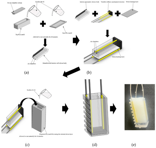
Figure 4.
Design and fabrication process of variable-stiffness soft pneumatic actuator. (a) Design and fabrication of the interior soft body layer; (b) combining the mechanical structure, interior silicon body, and strain-limiting layer; (c) forming the exterior soft body layer; (d) soft actuator CAD design; (e) fabricated soft actuator prototype.
After designing and fabricating a single soft actuator, two more actuators were fabricated and combined to form a variable-stiffness pneumatic soft gripper robot. A stepper motor housing was also designed and fabricated via 3D printing using PLA filaments. The soft actuators were connected to the stepper motor pulleys and the gripper system CAD design, which can be seen in Figure 5a below. The fabricated gripper mechanism mounted on an LM system can be seen in Figure 5b below.
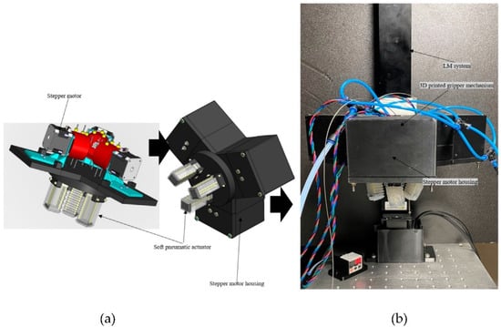
Figure 5.
Gripper mechanism. (a) Gripper mechanism CAD design; (b) fabricated gripper mechanism mounted on an LM system.
3. Theoretical Modeling of the Variable-Stiffness Pneumatic Soft Actuator
3.1. Pseudo-Rigid Body Model (PRBM)
When the three actuators that form the gripper are pressurized, it leads to a nonlinear bending motion. Since the actuator consists of a rigid–soft structure, its bending nonlinear motion can be modeled using the Pseudo-Rigid Body Model (PRBM), which is a technique introduced by Howell [30]. The PRBM technique is a simple method for analyzing nonlinear deflections of systems. The deflection of flexible members is modeled using rigid-body components that have equivalent force-deflection properties. The mechanism is then analyzed using rigid-link mechanism theory. The method is particularly useful in the design of complaint mechanisms. Different types of segments require different types of models. For each flexible segment, a PRBM predicts the deflection path and force–deflection relationships of a flexible segment. By attaching rigid-links at pin joints, the beam dynamics was modeled. In order to accurately predict the force–displacement relationships of the compliant segment, springs were also added to the mechanism. The key for each PRBM is deciding the position of the pin joints and determining the spring constants. In this analysis, the actuator’s single segment was modeled using this PRBM.
Figure 6a,b below show the schematic diagram of the actuator bending shape modeled as a large-deflection cantilever beam segment in which applying a vertical external force F at its free end causes it to bend from its undeflected position A (L, 0) to its deflected position À (a, b). The nearly circular path was accurately modeled by two rigid links that are joined at a pivot along the beam. Adding a torsional spring at the pivot represents the beam’s resistance to deflection. The pseudo-rigid-body characteristic pivot location is measured from the beam’s end as a fraction of the beam’s length. The fraction distance is γL and γ is the characteristic radius factor. The characteristic radius γL, is the radius of the circular deflection path traversed by the end of the pseudo-rigid-body link. It also represents the length of the pseudo-rigid-body link.
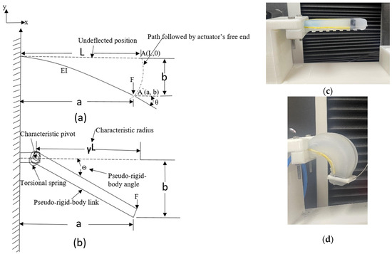
Figure 6.
PRBM modeling of the variable-stiffness soft pneumatic actuator. (a) Cantilever beam with force applied to its free end; (b) its Pseudo-Rigid-Body model; (c) undeflected position of fabricated actuator; (d) its deflected position when pneumatic pressure is supplied to its chambers.
The preceding pseudo-rigid-body approximation will be used to parameterize the deflection path, the angular deflection of the beam’s end θ, the load–deflection relationships, and Θ the pseudo-rigid-body angle. The pseudo-rigid-body angle is the angle between the pseudo-rigid-body link and its undeflected position. The cantilever segment with force applied to its free end and the Pseudo-Rigid-Body Model (PRBM) can also be seen in Figure 6 below. The undeflected and deflected positions of the fabricated actuator are, respectively, shown in Figure 6c,d below.
The x and y coordinates of the beam deflection are a and b, respectively. a and b can be calculated using Equations (1) and (2) below.
where a is the horizontal deflection, L is the actuator (beam) length, γ is the characteristic radius factor, θ is the angular deflection of the beam’s end, b is the vertical deflection, and Θ is the pseudo-rigid-body angle.
a = L (1 − γ(1 − cosΘ))
b = LγsinΘ
The value of the spring constant k at the joint can be calculated using Equation (3)
where k is the spring constant, kΘ is the stiffness coefficient, whose value is obtained via extrapolation based on the numerical data of γ on the numerical data table proposed by [30]. E is the Young’s modulus, and the second moment of area I = wh3/12, where w = beam width, and h is the height of the beam.
γ was obtained from (4) below.
where n is the direction of the applied load. In this analysis, since the beam was loaded with a vertical force, n = 0, and hence, γ can be computed.
The relationship between the applied load F and the pseudo-rigid-body angle Θ can be seen in Equation (5) below.
η refers to a parameter associated with the geometry and stiffness of the structure and can be calculated using (6) below.
The nearly linear relationship between the angular deflection of the beam’s end and the pseudo-rigid-body angle is shown in (7) below.
where Cθ is called the parametric angle coefficient. It is also obtained by extrapolating the value of γ from the numerical data table proposed by [30].
θ = Cθ Θ
Hence, the relationship between the applied load F and the deflection angle of the beam’s end is given in (8) below.
3.2. Experimental Results and PRBM Theoretical Validation
Here, a verification experiment was carried out such that the experimental values obtained were compared with the values of the respective PRBM parameters in order to validate the experimental results. During this process, the actuator was mounted on a QMESYS Universal Testing Machine (UTM) in such a way that the actuator is fixed at one end, and the free end is connected to the UTM by clamping using the connector consisting of fabricated 3D-printed PLA parts and AISI 304 steel material. The fixed material is also a PLA part fabricated via 3D printing. By applying different amounts of pneumatic pressure into the air chambers causes the actuator to bend at different angles θ which was measured using a protractor. The actuator’s tip deflection D was measured using a meter rule placed perpendicularly to it, and the respective applied tip forces at these pressures were recorded by the 20 kgf load cell located on the UTM. These tip forces were recorded by causing the UTM to pull the pressurized actuator vertically upward. The applied force data was collected from the UTM on a data PC. A PSAN-C01CV pressure sensor was used to record the respective amount of pneumatic pressures supplied into the air chambers and the pneumatic pressure source was from a Keyang air compressor 2.5 HP. The experimental setup is shown in Figure 7, and the obtained results are displayed in Table 1 below.
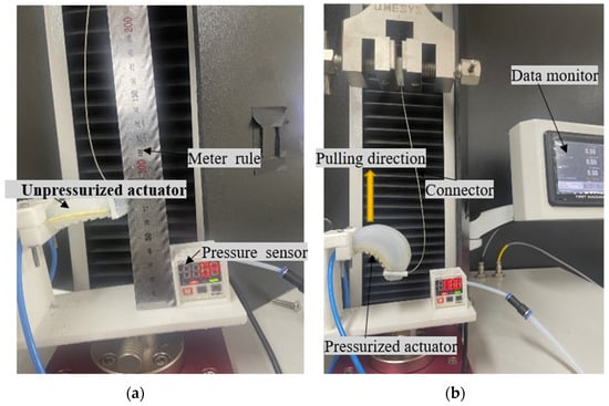
Figure 7.
Experimental setup and validation of the PRBM. (a) Actuator’s unpressurized state; (b) data reading during actuator’s pressurized state.

Table 1.
PRBM experimental results. (a) Known external forces of 4 N, 6 N, and 8 N were, respectively, applied at the tip of the soft actuator, and the resulting deflections were recorded. The respective theoretical deflections were then calculated using the PRBM equations and then compared with the experimental results to validate the PRBM modeling technique results and in (b) by applying the same amounts of external loads; the respective actuator’s tip bending angles θ were also recorded and then used to calculate the PRBM theoretical loads. The PRBM theoretical force values were then compared with the external force applied values to validate the results.
Looking at the displayed results in Table 1 above, it shows that the measured experimental results and the calculated PRBM results are very similar to each other. The close results validate the PRBM technique used in modeling the system’s dynamics. During the calculations, the value for Young’s modulus used was 0.025 MPa, as proposed by [31].
4. Variable-Stiffness Experiment
Variable-Stiffness Experimental Setup and Obtained Results
In order to characterize the bending stiffness of the actuator so as to determine the payload of the actuator, a variable-stiffness experiment was carried out. To test the enhancement for bending stiffness of the actuator when the mechanical structure for stiffness variation is embedded into it, we conducted a comparison experiment to test the bending stiffness of the actuator when the tendons are not pulled and when the tendons are pulled separately. During this study, the bending stiffness was defined as
where F is the applied force to the actuator and the deflection caused by the applied force. The experimental setup can be seen in Figure 8a below. Just like the experimental setup to validate using the PRBM in Figure 7 above, the actuator was mounted on a QMESYS Universal Testing Machine (UTM) in such a way that the actuator is fixed at one end and the free end is connected to the UTM by clamping using the connector consisting of two fabricated 3D-printed PLA parts (one part for connecting to the soft actuator and the other part for connecting to the UTM) and AISI 304 steel material. The fixed material is also a PLA part fabricated via 3D printing. Stiffness values were recorded by the 20 kgf load cell on the UTM by pulling the actuator vertically upward for different amounts of pneumatic pressures of 0 kPa, 50 kPa, 60 kPa, and the maximum pressure of 90 kPa supplied into the air chambers of the actuator without pulling the tendons. Stiffness values at these same pressures were also recorded by the load cell on the UTM while pulling the tendons. The recorded force data was collected from the UTM software on a data PC. A PSAN-C01CV pressure sensor was used to record the respective amount of pneumatic pressures supplied into the air chambers. To control the amount of pneumatic pressure supplied into the air chambers, a relay connected to a YM2T solenoid valve was used. The stepper motor used for pulling the tendons is LDO-42STH60-2004AC. The stepper motors were controlled using Arduino Uno connected to a PC. The experiment was carried out on the UTM at a speed of 20 mm/s. During each loading scenario, the experiment was carried out four times, and the mean value was computed in order to increase the data accuracy. The respective stiffness data recorded during these scenarios are displayed in Table 2 below. The configuration diagram for the experiment is shown in Figure 8b below.
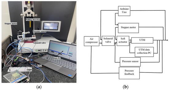
Figure 8.
(a) Variable-stiffness experimental setup and (b) experimental configuration.
Table 2.
Variable-stiffness experimental results.
Table 2 above shows the respective experiment scenarios, alongside their stiffness values, their stiffness percent increases. Comparing scenarios 1 and 2, in scenario 1, the actuator was not pressurized, the tendons were not pulled, and a stiffness value of 0.017 N/mm was recorded. On the other hand, in scenario 2, the actuator was still not pressurized, but the tendons were pulled, and a stiffness value of 0.042 N/mm was recorded, which is a 147.1% stiffness percent increase relative to scenario 1 due to pulling tendons. Comparing scenarios 3 and 4, in scenario 3, the actuator was pressurized to 50 kPa, but the tendons were not pulled, and a stiffness value of 0.044 N/mm was recorded. On the other hand, in scenario 4, the actuator was also pressurized to 50 kPa, the tendons were pulled, and a stiffness value of 0.108 N/mm was recorded, which is a 145.5% stiffness percent increase relative to scenario 3 due to pulling tendons. Comparing scenarios 5 and 6, in scenario 5, the actuator was pressurized to 60 kPa without pulling the tendons, and a stiffness value of 0.051 N/mm was recorded. On the other hand, in scenario 6, the actuator was also pressurized to 60 kPa, the tendons were pulled, and a stiffness value of 0.115 N/mm was recorded, which is a 125.5% stiffness percent increase relative to scenario 5 due to pulling tendons. Comparing scenarios 5 and 6, in scenario 5, the actuator was pressurized to 60 kPa without pulling the tendons, and a stiffness value of 0.051 N/mm was recorded. On the other hand, in scenario 6, the actuator was also pressurized to 60 kPa, the tendons were pulled, and a stiffness value of 0.115 N/mm was recorded, which is a 125.5% stiffness percent increase relative to scenario 5 due to pulling tendons. Comparing scenarios 7 and 8, in scenario 7, the actuator was pressurized to the maximum pressure of 90 kPa without pulling the tendons, and a stiffness value of 0.062 N/mm was recorded. On the other hand, in scenario 8, the actuator was also pressurized to 90 kPa, the tendons were pulled, and a stiffness value of 0.121 N/mm was recorded, which is a 95.2% stiffness percent increase relative to scenario 7 as a result of pulling tendons. The mean results of the force–displacement relationship are shown in Figure 9 below.
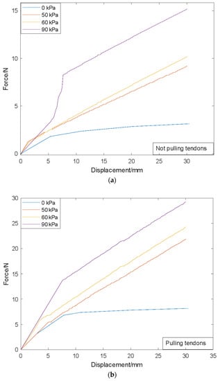
Figure 9.
Various stiffness states force–displacement graphs. (a) Without pulling tendons; (b) pulling tendons.
5. Application
By mounting the gripper system on an LM system, as shown in Figure 5b above, vertical pick-and-place movement gripping experiment was carried out on a set of target objects of different shapes, sizes, and weights, and a payload test was also carried out thereafter. The gripper payload was measured to be up to 2.075 kg, which gives a normal force value of 20.36 N (for the combined three actuators, and since the actuator body was made of silicon, the friction coefficient was assumed to be 1 when evaluating the gripping force), and hence, for a single actuator, the normal force value was 6.79 N. The gripper can grasp objects of diameter up to 60 mm. However, these results do not exactly match with the results obtained during PRBM measurement technique of the actuator, with a normal force value of 29.22 N, as shown in Table 2 above, hence a payload value of 2.979 kg. These differences in results between the values obtained during real-life payload measurements and the PRBM measurements are as a result of certain factors, which includes the assumptions made when deriving PRBM equations of motion in order to approximate the behavior of a compliant mechanism as a rigid body with flexible elements. These include various assumptions such as the rigid links in the mechanism do not deform or experience any deflection. This assumption simplifies the PRBM analysis by considering the links as perfectly rigid bodies. Another assumption made was that the compliant element (the soft actuator) was assumed to behave linearly within its operating range. This assumption implies that the flexure hinges exhibit linear elastic behavior and obey Hooke’s law. The PRBM model also assumes the flexible member only exhibits small deformations and deflections. It also assumes a linear force–deflection relationship between the applied force and the resulting deflection of the compliant member. This assumption simplifies the modeling and analysis by using linear stiffness characteristics. However, in real-life situations, all these assumptions are not valid, hence affecting the overall performance of the gripper, which also includes reducing the maximum payload of the gripper.
In order to determine the maximum payload of the gripper, a payload experiment was also carried out. During this experiment, an empty container was made to be gripped and lifted, and then objects were gradually added into the container until the gripper could no longer support the weight of the objects, which caused it to lose its grip, allowing the container to fall. The weight at this point was recorded as the maximum payload of the gripper. Figure 10 below shows the objects in a container while being gripped and lifted by the gripper.
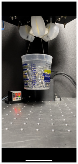
Figure 10.
Gripper maximum payload test.
Figure 11 below shows the target objects to be grasped, and their respective dimensions and weights are displayed in Table 3 below.
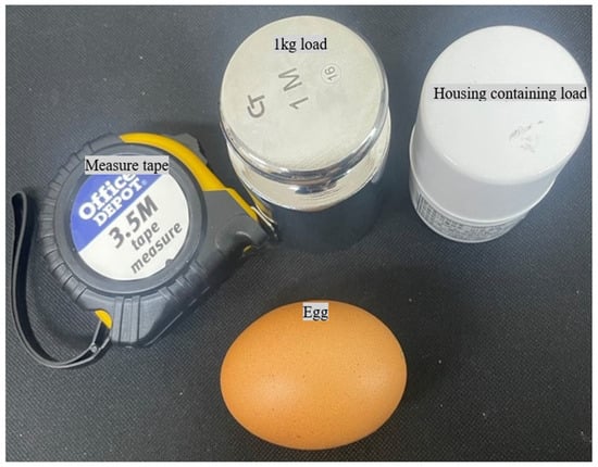
Figure 11.
Target objects.
Table 3.
Target objects parameters.
Figure 12 below shows the gripper while grasping and lifting the target objects of different shapes and sizes.
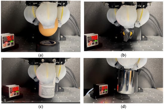
Figure 12.
Grasping of various objects. (a,b) Egg, measuring tape; (c,d) housing containing load, 1 kg Load.
6. Conclusions
In this study, we developed a variable-stiffness pneumatic soft actuator which incorporates a pneumatic structure for bending control and a mechanical structure for stiffness control. Three of these actuators were then combined to form a variable-stiffness pneumatic soft actuator. The overall body of the variable-stiffness soft gripper was made of silicon, and the internal mechanical structure was a combination of a PLA part manufactured via 3D printing and tendons manufactured from AISI 304 steel, and hence, it was manufactured at a relatively low cost. The variable-stiffness pneumatic soft gripper was developed as a three-finger gripper to mimic human fingers when gripping and lifting objects of different shapes, sizes, and weights. A single actuator was designed and manufactured to assume a rectangular shape, and the dynamics was theoretically modeled using the Pseudo-Rigid-Body Model (PRBM) technique. Experiments were then carried out to evaluate the actuator’s dynamics, and the experimental results were compared and verified using the PRBM technique. Also, variable-stiffness experiments were carried out at different stiffness states of the pneumatic soft actuator using the Universal Testing Machine (UTM), and it was discovered that by embedding the mechanical structure into the soft silicon body and pulling the tendons, the actuator’s overall stiffness can be increased up to 145.5% compared to when the actuator was just pressured without pulling the tendons. The tendons were pulled using stepper motors, and the amount of stiffness increase in the actuator depends on the pulling torque of the stepper motor, and based on the type of stepper motor used, the maximum stiffness of the actuator was measured to up to 0.121 N/mm and occurred at a pneumatic pressure of 90 kPa applied into the actuator’s air chambers. Furthermore, an object-grasping experiment was conducted, during which four target objects of various shapes, sizes, and weights were gripped and lifted at a 100% gripping success rate, which validates the objectives of the designed gripper. A payload test was also conducted, and the maximum payload the gripper can grasp and lift was measured to be up to 2.075 kg.
In the future, more work is expected to be performed on the gripper, like adjusting the gripper’s dimensions such that it can be used in gripping even objects with larger diameters. In addition, it is expected that more steps will be taken in increasing the user’s convenience by making the gripper smarter in such a way that object recognition technology during grasping will be incorporated into the gripper system through machine learning.
Author Contributions
Conceptualization, S.C.M.; methodology, S.C.M.; software, S.C.M.; validation, S.C.M.; formal analysis, S.C.M.; investigation, S.C.M.; writing—original draft preparation, S.C.M.; writing—review and editing, S.C.M. and Y.-J.P.; visualization, S.C.M.; supervision, Y.-J.P. All authors have read and agreed to the published version of the manuscript.
Funding
This research was supported by Basic Science Research Program through the National Research Foundation of Korea (NRF) funded by the Ministry of Education (2020R1I1A3073575) and by the Industrial Strategic Technology Development Program (20018270, Development of a gripper system for product variety to grasp unspecified objects of various shapes, weights and strengths) funded by the Ministry of Trade, Industry and Energy (MOTIE, Korea).
Data Availability Statement
Not applicable.
Conflicts of Interest
The authors declare no conflict of interest.
References
- Polygerinos, P.; Wang, Z.; Galloway, K.C.; Wood, R.J.; Walsh, C.J. Soft robotic glove for combined assistance and at-home rehabilitation. Robot. Auton. Syst. 2015, 73, 135–143. [Google Scholar] [CrossRef]
- Dutson, E.; Hashimoto, D. Soft robotic surgical training models: A review. Ann. Biomed. Eng. 2017, 45, 2030–2044. [Google Scholar]
- Liu, Q.; Sun, D.; Meng, Y. Soft robotics in manufacturing: Opportunities and challenges. Robot. Comput.-Integr. Manuf. 2019, 58, 228–242. [Google Scholar]
- Shahinpoor, M.; Kim, J.; Mojarrad, M. Ionic polymer metal composites: I. Fundamentals. Smart Mater. Struct. 2011, 10, 819. [Google Scholar] [CrossRef]
- Li, S.; Zhang, W.; Huang, Y.; Zhu, J. Stimuli-responsive soft robots: From electronic skins and muscles to applications. Actuators 2019, 8, 35. [Google Scholar]
- Wang, X.; Guo, S.; Xie, Y.; Liu, Y. Review of soft robotics: Challenges, advances, and perspectives. Front. Neurorobotics 2020, 14, 34. [Google Scholar]
- Tolley, M.T.; Shepherd, R.F.; Mosadegh, B.; Galloway, K.C.; Wehner, M.; Karpelson, M.; Wood, R.J. A resilient, untethered soft robot. Soft Robot. 2014, 1, 213–223. [Google Scholar] [CrossRef]
- Shepherd, R.K.; Ilievski, F.; Choi, W.; Morin, S.F.; Stokes, A.A.; Mazzeo, A.D.; Chen, X.; Wang, M.; Whitesides, G.M. Multigait soft robot. Proc. Natl. Acad. Sci. USA 2011, 108, 20400–20403. [Google Scholar] [CrossRef]
- Xu, L.; Wagner, R.; Liu, S.; He, Q.; Li, T.; Pan, W.; Feng, Y.; Feng, H.; Meng, Q.; Zou, X.; et al. Locomotion of an untethered, worm-inspired soft robot driven by a shape-memory alloy skeleton. Sci. Rep. 2022, 12, 12392. [Google Scholar] [CrossRef]
- Calderón, A.A.; Ugalde, J.C.; Zagal, J.C.; Perez-Arancibia, N.O. Design, fabrication and control of a multi-material-multi-actuator soft robot inspired by burrowing worms. In Proceedings of the 2016 IEEE International Conference on Robotics and Biomimetics (ROBIO), Qingdao, China, 3–7 December 2016; pp. 31–38. [Google Scholar]
- Kim, S.; Laschi, C.; Trimmer, B. Soft robotics: A bioinspired evolution in robotics. Trends Biotechnol. 2013, 31, 287–294. [Google Scholar] [CrossRef]
- Majidi, C.; Kramer, R.K. Soft-matter engineering for soft robotics. Adv. Mater. 2017, 29, 1703620. [Google Scholar] [CrossRef]
- Kim, K.; Choi, H.R. Wearable soft robots for human augmentation: A review. IEEE Access 2020, 8, 45015–45028. [Google Scholar]
- Popova, L.; Vitiello, N. Soft wearable robots for immersive virtual reality experiences: A review. Virtual Real. 2021, 25, 533–549. [Google Scholar]
- Asbeck, A.T.; De Rossi, S.M.; Holt, K.G.; Walsh, C.J. A biologically inspired soft exosuit for walking assistance. Int. J. Robot. Res. 2015, 34, 744–762. [Google Scholar] [CrossRef]
- Zhang, H.; Wang, S.; Li, W.; Li, H.; Li, Y. A soft pneumatic gripper with variable stiffness for handling fragile objects. IEEE Robot. Autom. Lett. 2020, 5, 2735–2742. [Google Scholar]
- Song, W.; Wu, Y.; Yan, J.; Xie, S. A modular soft gripper with variable stiffness for handling delicate objects. Soft Robot. 2021, 8, 123–131. [Google Scholar]
- Liu, X.; Chen, S.; Zhang, H. Variable stiffness pneumatic soft gripper for food packaging. J. Food Eng. 2021, 309, 110712. [Google Scholar]
- Wang, W.; Ma, W.; Ma, Z.; Liu, H. A prosthetic hand based on variable stiffness pneumatic soft grippers. Sens. Actuators A Phys. 2021, 325, 112743. [Google Scholar]
- Duenas, A.; Van Assel, I.; Vanderborght, B.; Lefeber, D. A Soft Gripper With Variable Stiffness Actuated by Shape-Memory Alloy Springs. IEEE Robot. Autom. Lett. 2019, 4, 4244–4251. [Google Scholar]
- Liu, Y.; Xiong, C.; Song, A.; Cheng, G. A hybrid soft gripper with pneumatic artificial muscles and cable-driven actuators for variable stiffness control. Soft Robot. 2019, 6, 332–341. [Google Scholar]
- Ham, K.; Jeon, J.; Park, Y. Development of Variable Stiffness Soft Robot Hand for Improving Gripping Performance. J. Korea Acad. Ind. Coop. Soc. 2018, 19, 47–53. [Google Scholar]
- Kim, B.; Kim, J.; Lee, K.; Choi, H.; Cho, K. Electromyography-based stiffness and force control of a cable-driven variable stiffness gripper. J. Intell. Mater. Syst. Struct. 2019, 30, 1214–1224. [Google Scholar]
- Sun, Y.; Liu, Y.; Pancheri, F.; Lueth, T.C. LARG: A Lightweight Robotic Gripper With 3-D Topology Optimized Adaptive Fingers. IEEE/ASME Trans. Mechatron. 2022, 27, 2026–2034. [Google Scholar] [CrossRef]
- Petković, D.; Pavlović, N.D.; Shamshirband, S.; Anuar, N.B. Development of a new type of passively adaptive compliant gripper. Ind. Robot. 2013, 40, 610–623. [Google Scholar] [CrossRef]
- Mao, Z.; Asai, Y.; Yamanoi, A.; Seki, Y.; Wiranata, A.; Minaminosono, A. Fluidic rolling robot using voltage-driven oscillating liquid. Smart Mater. Struct. 2022, 31, 105006. [Google Scholar] [CrossRef]
- Peng, Y.; Yamaguchi, H.; Funabora, Y.; Doki, S. Modeling Fabric-Type Actuator Using Point Clouds by Deep Learning. IEEE Access 2022, 10, 94363–94375. [Google Scholar] [CrossRef]
- Cianchetti, M.; Ranzani, T.; Gerboni, G.; Menciassi, A. A soft robotic arm inspired by the octopus. Adv. Robot. 2014, 28, 1603–1614. [Google Scholar]
- Bai, Y.; Song, A.; Chen, W. Design and analysis of a tendon-driven variable stiffness soft gripper. In Proceedings of the 2019 IEEE International Conference on Mechatronics and Automation, Tianjin, China, 4–7 August 2019; pp. 918–923. [Google Scholar]
- Howell, L.L. Compliant Mechanisms; Wiley-IEEE: Hoboken, NJ, USA, 2001. [Google Scholar]
- LucMarechal/Soft-Robotics-Materials-Database. Available online: https://github.com/LucMarechal/Soft-Robotics-Materials-Database (accessed on 6 September 2023).
Disclaimer/Publisher’s Note: The statements, opinions and data contained in all publications are solely those of the individual author(s) and contributor(s) and not of MDPI and/or the editor(s). MDPI and/or the editor(s) disclaim responsibility for any injury to people or property resulting from any ideas, methods, instructions or products referred to in the content. |
© 2023 by the authors. Licensee MDPI, Basel, Switzerland. This article is an open access article distributed under the terms and conditions of the Creative Commons Attribution (CC BY) license (https://creativecommons.org/licenses/by/4.0/).