1. Introduction
Just as the rapid development of digitalisation and the accompanying automation of production was recently referred to as Industry 4.0, today we can speak (with some exaggeration) of Construction Industry 4.0, thanks to the use of additive manufacturing technology in the construction industry. Extrusion-based additive manufacturing with cement-based materials, referred to as 3D concrete printing, is currently developing very rapidly and is beginning to move from the academic environment to the industrial environment. The number of possible applications of 3D concrete printing in the construction industry is growing sharply and so are the companies involved in this technology [
1,
2,
3].
In industrial applications related to 3D concrete printing technology, we very often encounter industrial six-axis robotic arms or gantry robots, the use of which may not be entirely suitable for this technology [
4,
5]. The kinematic structure of the aforementioned robots is usually not directly optimised for 3D concrete printing applications and they are usually equipped with closed control systems that do not give full freedom to the users for their control.
In this paper, our aim is to introduce and test the open control system platform of a unique robot for the 3D printing of buildings. This platform, thanks to the industrial control system used, allows easy integration into the industrial process and, at the same time, its openness makes it a suitable platform for educational and research purposes. The openness of this system is demonstrated through the implementation of model-based control of the experimental model of the printing robot, serving as a test bed for the final version of the printing robot.
The paper is organised as follows: A review of the related literature is found in
Section 2.
Section 3 presents the platform of the open control system, including a description of low-level torque control and the G-code interpreter design.
Section 4 describes the design and implementation process of the model-based control and presents the mathematical model of the experimental robot, the identification of its inertial parameters, and the control design.
Section 5 is devoted to a description of the experiment testing the control system.
Section 6 describes the control system for the final robot for 3D printing of buildings, followed by a discussion in
Section 7 and our conclusions and future work in
Section 8.
2. Background and Related Work
As 3D concrete printing technology itself has received considerable attention recently, a number of articles have been devoted to issues of 3D printing technologies, aspects of concrete mix design and effective properties of printed concrete [
6,
7], and modelling and simulation of 3D printing of cement-based materials [
6], but little attention has been paid to the printing devices themselves. Very few publications give details of the control systems of the printing devices and the software used. Therefore,
Section 2.1 mentions in some detail several publications that contain this information.
Section 2.2 presents general approaches to robot control and their possible integration for new generations of printing robots and
Section 2.3 presents possible hardware implementations of their control systems.
Section 2.4 provides a summary and assumptions for our solution.
2.1. Printing Robots and Their Control Systems
Some of the first robots used for the application of 3D concrete printing were gantry robots. The main reason for this is probably that gantry robots are relatively easy to control and are capable of carrying heavy loads. In [
8], a cost-effective solution is described for the mechanical and control system of a gantry robot that allows printing of a free curved structure made of fibre-reinforced mortar without a mould. The gantry robot consists of three-axis linear actuators on a box-like support frame. The linear actuators are realised by a belt or ball screw according to the requirements of each axis. The individual actuators are driven by brushless DC servo motors with gearboxes. The size of the usable print area is 1300 mm × 950 mm × 800 mm, with the
x-axis being the longest axis and driven by two synchronous motors in a parallel arrangement for better mechanical load capacity. The maximum speed of the
x- and
y-axes is set to 500 mm/s and that of
z-axis is set to 300 mm/s. The control system used here is an embedded Personal Computer (PC) with a PC/104 interface, which sends positioning instructions to the individual servocontrollers via a Controller Area Network (CAN). As far as the software is concerned, the control PC runs a G-code interpreter which calculates the position trajectory with a maximum frequency of 500 Hz and then sends the commands to the subcontrollers in real time. The control system uses Matlab to simulate the trajectory to check the position trajectory and prevent system failures. According to the authors, the advantage of their solution lies in the distributed control system which aims at cost reduction, flexibility, scalability, and deployability for various applications, such as the construction of various atypical structures and unattended construction in hazardous locations.
Six-axis industrial robots were deployed a little later than gantry robots in the application of 3D concrete printing, but with their use came the ability to print much more geometrically complex objects. Six-axis industrial robots are significantly more complex to control than gantry robots, but have a greater freedom of movement and take up less space.
One of the first papers to introduce 3D concrete printing using a six-axis industrial robot was [
9]. The printing here is executed with a six-axis ABB 6620 industrial robot, with the entire printing assembly consisting of a robot-mounted print head and two peristaltic pumps, one for the premix and the other for the accelerator of the printing mix. An Arduino Mega 2560 micro controller is used here as the control system, which controls the print head, pumps, additive dosage, and any emergency stops. In terms of software, the 3D printing system is controlled using the Grasshopper/Rhino v.5.0 framework [
10] and the HAL plugin [
11] is used to control the robotic arm. This plug-in handles the programming of the toolpath and the control of the robot motion during 3D printing. No information about the robot or the printing area is given in the paper, but according to the catalogue data, to complete the picture, the robot reach w as 2.2 m, the robot payload capacity was 150 kg, the robot weight was 900 kg, and the estimated printing area was around 9 m
. The authors state that the main advantage of using a six-axis printing robot is the possibility of non-horizontal and indirect slicing of the printed object and thus the possibility of printing geometrically complex objects. Another advantage, according to the authors, lies in the ease of implementation of this technology in the construction industry without the need to develop special printing machines. This printing methodology is currently being industrialised, for example, by the French company XtreeE (XtreeE, Rungis, France) [
12].
Since 3D printing of buildings is mainly performed in the horizontal plane, the use of six-axis robots commonly used in industry may incur significant inefficiencies due to the large energy consumption due to gravity compensation for the unused robot axes. When using gantry robots, the problem of limited range arises again, where the robot’s print area is smaller than the robot’s footprint. Another problem with Gantry robots is that they require a significant amount of energy to transport and install.
Due to its specific requirements for printing robots, 3D printing technology in the construction industry has resulted in the emergence of custom non-standard robotic arms designed for large-scale 3D printing [
13,
14,
15]. Large-scale 3D concrete printing using robots can be achieved in various ways, for example, by using large-scale robots [
16]. An interesting solution, which provides a larger working area and improves the transportability of the printing system, is the use of parallel cable robots, referred to as a ”cable-suspended platform”. The main advantages of cable-suspended platforms are the large printable area, cost, transportability, and reconfigurability.
In paper [
17], a large-scale 3D printer is presented that uses a parallel cable robot with six degrees of freedom for printing. Here, polyurethane foam is used as the printing material and shaving foam as the support material for proof of concept. The maximum printing area of the robot is formed by a hexagon with a side length of 1.22 m, while in practice, the robot usually moves in a working area that is significantly smaller and is formed by a cylinder with a radius of 0.5 m in order to achieve the required robot accuracy. The figures for the maximum print height in the vertical axis are not clearly stated, with the authors stating that the best results in terms of contour are achieved between values of 1.1 m and 2.1 m. The development environment used here is RT-Lab, which is a real-time simulation software environment and is fully integrated into Matlab/Simulink. A PC with a real-time operating system (QNX) installed is used here as the control system. The real-time computer is connected to all the physical hardware and communicates with the PC via an Ethernet network. The individual axes are driven by servo drives which are pulse width modulation (PWM) controlled. According to the paper, the main advantages of using a rope robot are its easy portability and reconfigurability. The system can construct any 3D geometry and is also equipped with geometric feedback, which is used to detect and correct errors during printing. The authors also cite several disadvantages of the rope robot compared to conventional gantry systems, including a lower accuracy, more complex control, and the difficulty of routing cables and hoses transporting the print material to the robot’s end effector. The leads to the robot end effector exerting an external force on the effector and also presenting a kind of obstacle to the robot path planner, which must ensure that the cables do not interfere. Focusing on a specific application of printing with this robot, the authors report that they printed a 2.16 m tall sculpture (which was composed of three pieces) from polyurethane foam. The printing speed of this robot was around 100 mm/s, with an error of less than 10 mm.
A completely different approach to achieve large-format 3D printing, which we present here for the sake of completeness, is the so-called swarm approach. In this approach, instead of a single large robot, multiple cooperating robots are used, e.g., on mobile platforms [
18].
2.2. Possible Control Methods for the New Generation of Printing Robots
Whether we consider large-format robots or robots with non standard kinematics for 3D concrete printing technology, we always need to control such robotic arms in some way. The control system of custom robots must be highly flexible and be able to control any kinematic structure of the robotic arm.
Robotic systems are highly nonlinear and dynamically coupled, which pose many challenging tasks for robot controllers. Since traditional linear control approaches cannot be readily applied, increasingly sophisticated tools from nonlinear control theory are being developed to control robotic systems. In terms of robot control, a number of approaches have been described, such as feedback linearisation techniques [
19], computed torque control (CTC) [
19], and inverse dynamics control (IDC) [
20], including their modified versions such as adaptive and robust control strategies addressing model uncertainties and robustness to model uncertainties. The most commonly used adaptive control strategies for robotic systems are model reference adaptive control (MRAC) and sliding mode control (SMC) [
21].
The aforementioned control methods are now well described and are often discussed, but the question remains of how to easily implement these advanced control approaches on real robotic arms. Most of the mentioned control approaches have been published based on the results of numerical simulations in the Matlab/Simulink environment.
If we focus specifically on the control of robotic arms for 3D printing applications, there is currently not much information available regarding the specific control approaches used, probably due to the majority use of standard industrial robots for this application that have their own control system. For example, in paper [
17], a classical PID controller tuned by the Ziegler–Nichols method is used to control the individual actuators of a printing rope robot. Article [
22] deals with the fuzzy control of a gantry robot, which in general could be used for a 3D concrete printing application.
However, if we consider that this technology will expand in the future, we can expect that increasingly more special robotic manipulators designed specifically for the application of 3D concrete printing will be developed, along with specific control approaches that will be optimised for this application.
The aforementioned adaptive control methods seem to be possible approaches, where, for example, the variable mass of the end effector (due to concrete flowing in and out) or different variants of optimal control, e.g., to optimise energy consumption [
23,
24], could be considered for adaptation, as energy consumption may be a key factor in terms of the sustainability of this technology.
2.3. Possible Hardware Realisation of Control Systems for the New Generation of Printing Robots
The mentioned robot control methods will need to be tested against the requirements of 3D concrete printing technology. However, the question remains of how to implement these control approaches on real robotic manipulators as simply and quickly as possible.
The answer to this question is the use of an open control system. Several open control architectures have been developed and discussed in [
25,
26]. However, their use has remained within a rather small group of researchers. These architectures are hardware based on personal computers (PCs). In the aforementioned publications [
8,
17], personal PCs were also used as control systems for the cable-suspended robot and the gantry robot. The use of a PC as a control system is advantageous mainly because of the reduction in software development costs due to the possibility of using high-level programming languages. The main disadvantage is that standard PCs are not robust and reliable enough for deployment in an industrial environment. The use of an industrial control system for controlling press robots seems to be an interesting idea.
Increasingly, we are seeing control systems based on Programmable Logic Controllers (PLCs) for custom robots. Let us give some examples: in paper [
27], a PLC-based control system is used to control robotic complexes for construction and building printing. In paper [
28], PLC-based control is used to control a variable-scale modular 3D printing robot for building interior walls.
There are several reasons for using PLCs as control systems for custom robotic arms. PLCs are used in industrial environments and they are robust, reliable, and easy-to-use control systems that have enough computing power to perform complex mathematical calculation tasks using various programming languages due to the ever-increasing computing power nowadays. PLC-based robotic control nowadays even represents an interesting alternative to OEM robotic control, as it allows the use of a unified platform throughout the manufacturing process [
29].
2.4. Summary
Our research team at the Technical University of Liberec is researching the technology of 3D printing of buildings from concrete using a special printing robot. With regard to the application of 3D concrete printing, a unique printing robot with a range of 5.6 m has been designed, the design of which is based on the Selective Compliance Articulated Robot Arm (SCARA) structure with an added axis of rotation. The added degree of freedom increases kinematic and dynamic flexibility, which is advantageous, for example, when printing a break in a printed curve. In the case of printing a curve break, the entire printing robot mechanism does not have to stop, but only the end point of the robot is stopped (while the last robot link is rotating) and the other robot links can continue to move without losing kinetic energy. Another advantage is the increase in the robot’s dexterity, which is manifested, for example, in the possibility of printing behind already printed objects. Combined with the fact that the links of the printing robot move mainly in the horizontal plane (vertical movement occurs only when moving to the next printed layer) without changing their potential energy, thus naturally avoiding unnecessary losses, the aim of this technical solution of the printing arm is a significant energy saving when printing buildings. A detailed description of our design of the kinematic structure of this robot is given in [
30].
During our studies, several devices designed for proof-of-concept 3D printing have been built. The first device was a classic gantry robot [
31] based on a computer numerical control (CNC) core. The next device was based on the kinematic structure of the final printing robot and it was a simplified experimental model of a 1:4 scale printing robot; this model was designed to test the concept of the control system [
32]. The last device we are currently commissioning and testing is an experimental printing robot scaled 1:2 to the final printing robot and with the same kinematic structure as the final printing robot. Printing Mantis has a reach of 2.6 m and a payload capacity of 35 kg and represents a relatively large robotic arm, suitable for verifying key aspects from a control perspective for a 3D concrete printing application.
This paper presents an open control system that, thanks to its openness and unified platform, will enable simple and fast analysis and testing of key aspects in terms of the control and guidance of a printing robot for additive manufacturing applications in the construction industry. The control system has new features, such as torque control, allowing the implementation of custom low-level control algorithms. Furthermore, it is equipped with sensors in the form of inclinometers and light detection and ranging (Lidar) for the possibility of self-levelling of the printing table and localisation in space, and last but not least, the issue of a G-code interpreter is addressed. This paper describes the testing of the zero generation of this control system on the task of implementing model-based control for an experimental robotic arm, and then the final control system that is currently deployed on the experimental printing robot is described and tested.
3. The Open PLC-Based Robot Control System
The open control system of the printing robot is based on a standard industrial PLC/PC from Bernecker + Rainer Industrial Automation (B&R) company (B&R Industrial Automation GmbH, Eggelsberg, Austria) and the openness of this system is achieved by the use of an ”automatic code generator”. The automatic code generator converts control models from the Matlab/Simulink environment to automatically executable code on the PLC in the C/C++ programming language [
33].
This control system concept allows us to create software using standardised function blocks and libraries, or mapp components, combined with the ability to implement more sophisticated control approaches in the Matlab/Simulink environment.
Figure 1 demonstrates the concept of an open PLC-based control system of a printing robot, where PLK is an Ethernet powerlink bus, SDL is a shielded data link connector and HMI is a human–machine interface.
3.1. Software
The software of the robotic arm uses four layers of mapp–mapp motion, mapp services, mapp view, and lastly mapp safety.
Figure 1 shows the block scheme with layers. From the programmer’s point of view, the maps provide functional blocks, functions, and configuration files for easier software development. They then provide the machine operator with an intuitive interactive environment that makes the machine easier to control. More information about using the mapp components (mapp Motion, mapp View and mapp Services) can be found in article [
31]. In addition, mapp Safety is used in the control system to ensure safe operation of the printing robot.
Mapp Safety allows complete integration of safety technology into the mapp framework, making it easier to create, maintain, and diagnose safety applications. If the readily available user’s human–machine interface (HMI) application is not sufficient for the customer application requirements, a uniform mapp interface facilitates the programming of more complex functions [
34].
3.2. Basic Control System Processes
One of the basic functions of robotic manipulator software has always been to perform four basic processes that enable robot integration into an automation system: motion trajectory generation and tracking, motion/process integration and sequencing, human–machine interface, and information integration [
19].
Motion Trajectory Generation and Tracking: Important aspects of motion generation for robotic manipulators include the range of manipulation that can be programmed and the ability to perform controlled programmed motion using real-time control at the servo level. Mapp Motion components are used for trajectory generation and motion tracking, combined with automatically generated task created via Matlab/Simulink that handles timing and motion interpolation.
Motion/Process Integration: This process involves coordinating the motion of the manipulator with process sensors or other devices. The most primitive process integration takes place through digital inputs/outputs (I/O) or in their readout via the control PLC. A somewhat more sophisticated error-free process integration is handled through mapp Safety. Technology mapp Safety provides a quick implementation of safety requirements to the project. The application is separated from normal applications and it runs on the special safety PLC, whose operation is independent. The main purpose of mapp Safety is user safety. It reacts to pressing the TOTAL stop button, turns off the activation control on the Acopos inverter, and stops the machine.
Human Integration: The human–machine interfaces of the controller are essential to its operation, handling the quick setup and control of robotic systems. This interface is handled through mapp View. The visualisation receives information about function blocks and variables enabled on the Open Platform Communications United Architecture (OPC UA) server. Personalised content is solved by multi-client and multi-user access. A view of the applications is possible on mobiles, tablets, computers, or any device with a web browser. The robotic arm with final HW generation uses a TFT touch automation panel with a 54.64 cm diagonal large screen and a metal bar containing control elements. The application is divided into five pages: the main page, the table page, the alarm page, the audit page, and the service page with all limits and parameters. The most important page for the control arm is the main page. This page provides three types of control of the robotic arm: basic positioning, tool centre point (TCP) mode, and lastly trajectory mode.
Information Integration: Based on the requirements for Industry 4.0, information is one of the key aspects for a machine. Information can be different types: machine, user, program information, etc. Mapp Services technology is used for information integration and through the Audit feature, one can store user, machine, and program data in the user memory or visualise it in a graph. The stored information can be used for machine servicing or operator checks. Another widely used information source is, for example, a screen from an industrial camera that can be implemented in a visualisation application.
3.3. G-Code Interpreter
The G-code interpreter algorithm has been developed in two variants. The first variant is a user solution, where the user only needs to upload (e.g., via a USB flash drive) a 3D model of the printed object converted into G-code format. The control system then provides, using the Interpreter configuration file included in mapp Motion, the time-based code handling and sequential positioning of the robot’s print head while taking into account kinematic constraints. In this case, the effective positions of the robot joints are calculated using the custom mechanical system component of mapp Motion. This component allows to create a non-standard mechanical system using a configuration file. In our case, we have created five configurations with individual solutions to the inverse kinematics problem, see
Section 4.1, and the user can choose the desired variant according to the requirements of the printed object.
The second solution is a research solution, where G-code conversion is solved using a custom G-code interpreter created in the Matlab environment and the inverse kinematics problem is solved using an automatically generated task created via Matlab/Simulink. This solution allows us to have a significantly more complex control of the arm with the ability to optimise its motion.
In both cases, the desired print head position path and material application speed are obtained using special software that provides the conversion of the CAD model of the printed object in STL format into a G-code containing the endpoint coordinates and parameters for the temporal parameterisation of the motion path. For this purpose, we will use the software StarSlicer [
35] developed by our team or the commercially available software Grasshopper [
36].
Figure 2 demonstrates demonstrates two variants of the G-code interpreter.
3.4. Low-Level Torque Control Design
In order to be able to implement more advanced control methods (model-based methods), it was necessary to solve the implementation of torque control, ideally real-time torque control, in addition to the classical position/velocity servo control. In terms of standardised motion control, the basic function blocks for position and velocity control (MC_MoveAbsolute, MC_MoveRelative and MC_MoveVelocity) are available according to the PLCopen standard.
The standardised function block MC_TorqueControl is used for standard torque control applications (e.g., for winding applications, etc.). However, this function block is unsuitable for our application because it does not allow cyclic torque input and also has a speed limitation. For the real-time torque control capabilities of the robotic arm, it was necessary to solve the problem of cycling the torque and overriding the speed constraint that results in speed saturation when the motor is lightened.
Different ways of solving these torque control requirements were tested, and finally the following solution was successfully implemented to realise cyclic torque input in the absence of speed constraints.
The final solution of the real-time torque control possibility can be seen in
Figure 3. This solution consists of eliminating the speed and position controller for the cascaded servo control structure and then cyclically writing the appropriate parameter identifier (Par Id) with the desired torque to the Acopos servo amplifier. The whole control is controlled by a model created in Matlab/Simulink, which provides the timing of the cyclic input. During testing, the method worked very well and proved to be successful.
3.5. Hardware
In the first phase of development of the open control system, a so-called zero generation robotic platform was developed consisting of a simplified 1:4 scale model of a printing robot that serves as a test bed controlled by a simplified control system called Zero HW generation. Zero HW generation contained a lower power PLC 5APC2100 from the company B&R with an Acopos invertor and three axes with synchronous servo motors and planet gears. Arm control has been solved with an intuitive visualisation that can run on any device with a web browser. The main purpose of the design of the zero generation robotic platform was to verify the basic motion, torque control, and the possibility of deploying advanced control, without the risk of destroying the large and expensive final platform and also from a safety perspective.
In the second phase of the development of the open control system, a first-generation robotic platform was developed. This robotic platform contains a 1:2 scale printing robot relative to the final printing robot, which is controlled by a control system that is identical to that of the final printing robot, hence the name final HW generation. Final HW generation brought improvements to the hardware configuration. The powerful PLC 5PC910.SX02 from the company B&R, synchronous motors with precision harmonic gears, Safety PLC, an HMI panel and a robust aluminium construction were used.
The first-generation robotic platform includes a printing robot that meets the requirements for an industrial robotic arm that can carry the 3D printing head and print the structure. The zero-generation robotic platform serves as a test bed for testing the open control system before deploying it on the first-generation robotic platform and the final printing robot.
The individual HW configurations of the robotic platforms are shown in
Figure 4.
4. Modelling of the Zero Generation Robotic Platform
As mentioned in the previous section, a simplified experimental arm together with a simplified control system, collectively referred to as the zero-generation robotic platform, was developed for initial testing. More information about these devices can be found in [
32].
This simplified control system is based on the same concept as the final control system for the final printing robot. The results obtained should therefore be easily transferable to the final control system and the 1:2 scale printing robot, which is currently being commissioned and tested. More information about the 1:2 scale printing robot can be found in [
37]. Therefore, the capability of the proposed open control system was first analyzed and verified on the zero generation robotic platform. The general objective of testing the openness of the proposed control system is to demonstrate the implementation of model-based control. To do this, a kinematic and dynamic model of the robot under test must first be derived. The kinematic parameters of the simplified model of the printing robot are given in
Section 4.1.
Section 4.2 presents its equations of motion obtained using the Euler–Lagrange approach. Finally, a set of minimum inertial parameters, the so-called based inertial parameters in which the equations of motion can be expressed and rewritten into a linear relation are established in
Section 4.3.
4.1. Simplified Model of the Printing Robot and Its Kinematic Model
For the purpose of testing the open control system, a simplified 1:4 scale model of the experimental model of the printing robot was designed. It is a redundant planar robot with 3DOF realised by three articulated links, which are made of steel plates.
Figure 5 demonstrates the kinematic structure and kinematic parameters of the printing robot model.
The direct kinematics problem can be solved quite easily; the transformation equations for the arm endpoint coordinates are as follows [
32]:
The solution to the direct problem consists of simply plugging in the joint angles and calculating the corresponding
x and
y coordinates. The solution of the inverse kinematics problem is a much more difficult and complex problem. Due to the redundant degree of freedom of the robot manipulator, the corresponding Jacobi matrix is of type
and there is no inverse representation. The problem consists of solving a singular system of equations within the inverse robotics problem, respectively, finding the angles
for a given point with
coordinates. In general, we have several possible solutions [
30,
33]:
Choose one of the angles as a parameter and calculate the rest;
Choose a fixed constraint between the angles to obtain the next equation;
Determine the angles as an extremal problem for the chosen optimisation criterion.
The first two options are suitable for finding the analytical solution of the inverse problem. The first solution option gives three more possible solutions by choosing the individual angles as variables. For the second solution option, a constraint is introduced, which in general can be implemented in any number of ways, but for simplicity and practical applications, it makes sense to consider a linear constraint that leads to the other two solution options.
Paper [
30] deals with the complete derivation of the inverse problem of the kinematics of a printing robot. Here, the inverse problem is transformed to the complex plane, where it is then solved using exponential functions. In this paper, all five mentioned options for the analytical solution of the inverse kinematics problem are derived.
4.2. Dynamic Model of the Simplified Printing Robot
A rigid body model, derived from the Euler–Lagrange formulation, was used to derive the robot dynamics. The dynamic model of the robot manipulator with friction included can be expressed in matrix form by the following equation:
where
,
is an
inertia/mass matrix of the robotic manipulator, which is symmetric and positive definite,
is an
matrix of Coriolis and centrifugal forces, and
is an
vector of friction forces, which is most often represented by the viscous and Coulomb friction components:
where
and
are
diagonal matrices with coefficients corresponding to individual joints. Furthermore,
is the gravity vector and
is an
vector of generalised forces/torques.
4.3. Base Inertial Parameters
In the previous subsection, a dynamic model of the robot in
Section 4.2 was derived using Lagrange’s equations, which include the usual nonlinear functions
and standard dynamic parameters that appear in the matrix of moments of inertia of the
i-th member of the robotic arm:
where
, and
are principal moments,
, and
are denoted products of inertia of link
i,
,
, and
are the coordinates of the centre of gravity, and
are masses with respect to the
i-th link frame, respectively.
Let us group the standard dynamic parameters into two vectors.
is a vector whose elements are masses, inertial parameters, and the Cartesian location of the mass centre of robot’s links and
is a vector that contains the friction parameters of the robot’s joints as follows:
Using the regressor matrix Y, which depends only on the kinematic variables, it is always possible to rewrite the robot dynamic model (
1) in a linear form with respect to the standard dynamic parameters
where the vector
A number of standard dynamic parameters do not play a role in the dynamic model of a particular robot, which is reflected by the fact that the corresponding columns of the regressor matrix are zero. Some of the standard parameters may only appear as fixed. The corresponding columns of the regressor matrix are linearly dependent. We can isolate
independent groups of parameters
and split the matrix
into two parts, with the second group containing the dependent (or zero) columns as
for the respective constants
of matrix
.
The dynamic coefficients can be determined heuristically by rearranging and merging the individual dynamic parameters, and in [
38,
39], rules for obtaining the dynamic coefficients according to the kinematic structure of the robotic manipulator are given. Dynamic coefficients can also be determined by numerical procedures using SVD (singular value decomposition) or QR decomposition [
38]. In our case, the base inertia parameters were determined heuristically due to the low number of degrees of freedom.
5. Testing the Zero Generation Robotic Platform—Experiment Design
In order to demonstrate the openness of the control system, an experiment was designed to cover all the steps needed to implement model-based control.
First, a kinematic and dynamic model of a scaled printing robot was created in the Matlab/Simulink environment based on Equations (
1)–(
3). These models were verified by comparing them with the models created through the Matlab Robotic System Toolbox. The dynamic model of the robot was rewritten in linear form with respect to the base standard parameters (see Equation (
7)) and the base inertia parameters were heuristically determined with respect to the full rank of the regressor matrix.
Subsequently, we proceeded to design an experiment for parametric identification of robot inertia parameters using a classical procedure consisting of moving the robot along a specially designed identification trajectory (also known as an excitation trajectory) and then measuring the torque of individual robot links [
40].
The design of the identification experiment consisted primarily in the selection of a suitable excitation trajectory providing sufficient excitation of the robot dynamics to manifest all dynamic parameters and thus to achieve a fast and accurate estimation of these parameters even in the presence of disturbances. For possible trajectory optimisation and further signal processing, a trajectory composed of the sum of harmonic functions, which is periodic and band limited, was used [
40]. The joint trajectory of each axis can be written as a finite Fourier series of the sum of harmonics:
where
L is the selected number of harmonics,
is the selected signal frequency, and the coefficients
,
, and
can be calculated through the optimisation procedure.
It is convenient to obtain the excitation trajectory for robot identification by solving an optimisation problem because in least squares methods it is proven that to dampen the effect of noise in the computations, the condition number of the regressor matrix Y must be minimised.
The excitation trajectory parameters were optimised in Matlab/Simulink using the
fmincon function (nonlinear minimisation with constraints) and the SQP (sequential quadratic programming) algorithm. An objective function minimising the condition number of the regressor matrix was chosen to achieve the best numerical stability for the subsequent least squares parameter estimation [
41].
The motion constraints chosen here limit the positions, velocities, and accelerations of the joints and the position of the robot’s end effector in the Cartesian space. These constraints are chosen to respect the physical capabilities of the robot actuators while preventing collisions between the robot and objects in its environment (considering a forward kinematics problem).
Based on the obtained inertia parameters, a dynamic model of the robot was constructed and we proceeded to design a control-based model to control the scaled model of the printing robot. For the purpose of this paper, the classical feed-forward control in the form of inverse dynamics compensation (FFW) + PD control [
42] was chosen.
where
and
are the position and velocity gain (or damping), respectively, which are typically diagonal. The feed-forward term provides the joint forces required for the desired manipulator state (
) and the feedback term compensates for any errors due to uncertainty in the inertial parameters, unmodelled forces, or external disturbances.
Experimental Results
The experimental setup consists of an experimental model of the printing robot, shown in
Figure 6, and a prototype open PLC-based control system. In order to identify the inertia parameters, the excitation trajectory was designed and optimised in the Matlab/Simulink environment, see Equation (
10). The optimisation of the excitation trajectory parameters led to the minimisation of the condition number of the regressor matrix to a value of 2.8.
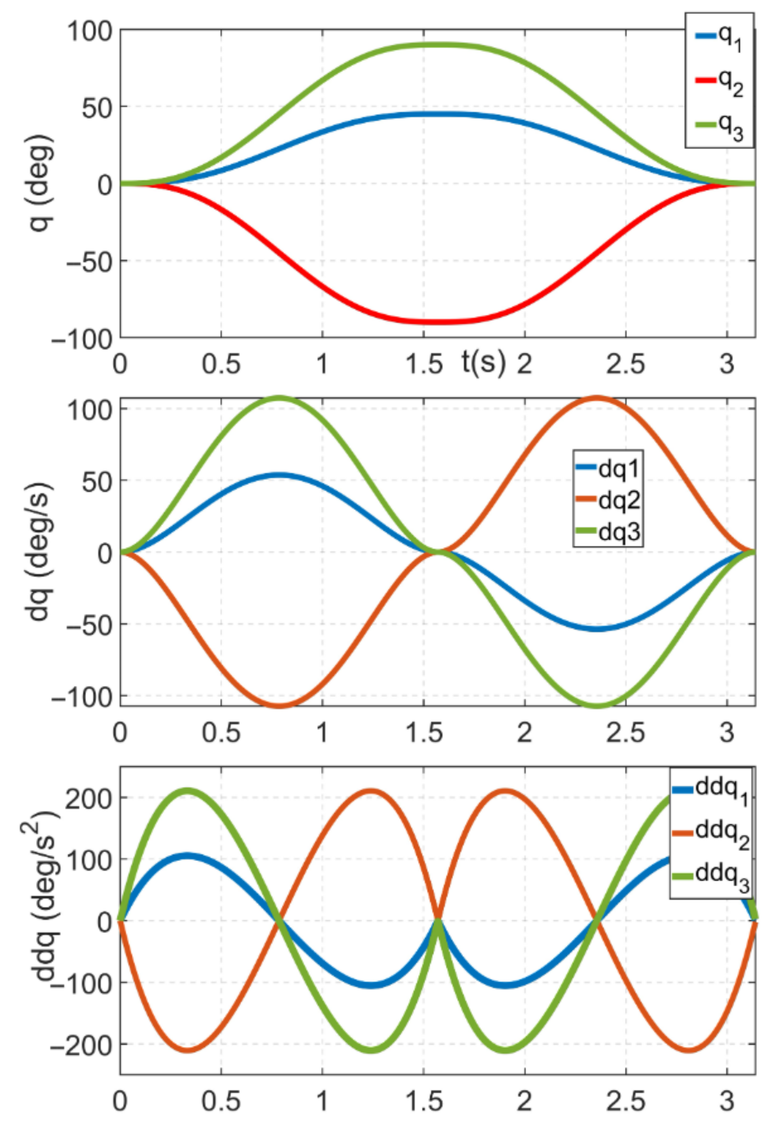
Figure 7 shows the excitation trajectories for the experimental model of the printing robot after solving the optimisation problem, given that
and
, as well as L = 5.
Subsequently, the excitation trajectory was implemented in an open control system via an automatic code generator, where each joint was controlled in “trajectory control mode” through decentralised control implemented by cascade control of the control system’s servo amplifier. Joint torque signals were recorded during this motion with a sampling period of 400
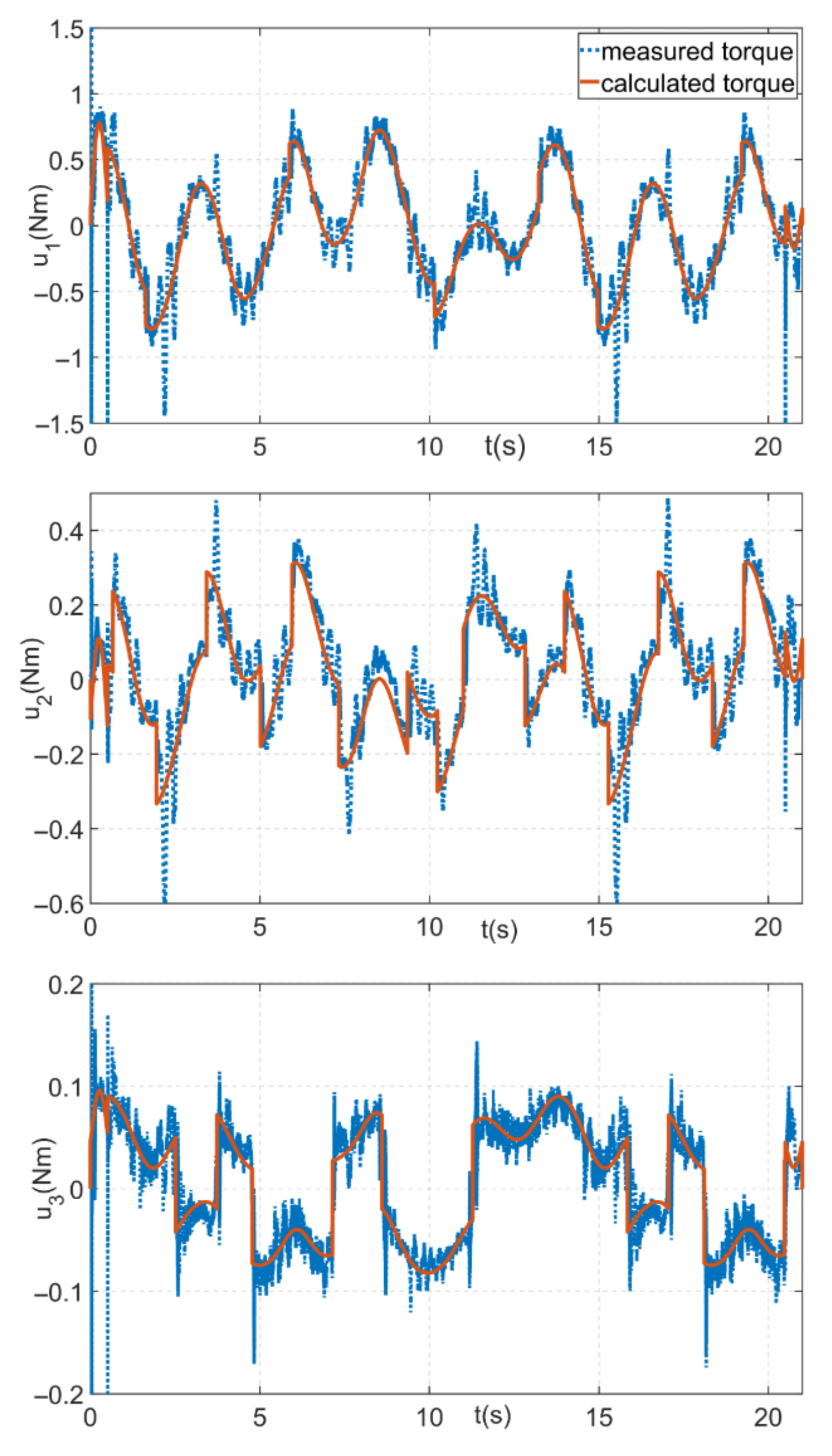
s. Then, the base inertial parameters were calculated and compared with the inertial parameters obtained from the 3D model of the experimental model of the printing robot using Autodesk Inventor. To compare the measured and reconstructed torques, the motion of the robotic arm along a different excitation trajectory was implemented and the torques on each axis were recorded. The comparison of the measured joint torques with the torques reconstructed by calculation from the identified parameters according to Equation (
7) is shown in
Figure 8, where
,
, and
directly correspond to the torques on the individual actuators of the robotic arm.
The results of the identification, the symbolic representation of the individual base inertia parameters, and the comparison of the parameters obtained from the identification against those obtained from the 3D model are shown in
Table 1.
If we consider the parameters obtained from the model as the actual parameters of the arm, the maximum percentage error of the parameter estimation would be less than 28 percent, which is not the best result. In reality, however, the assumption of considering the inertia of the parameters obtained from the 3D model as the real ones is not very relevant, because the 3D model has limited accuracy and, in addition, the influence of, e.g., supply cables, etc., on the arm. From the presented traces of torques comparing the estimated and actual torques, it can be seen that the torques calculated from the identified parameters represent the measured torques relatively well.
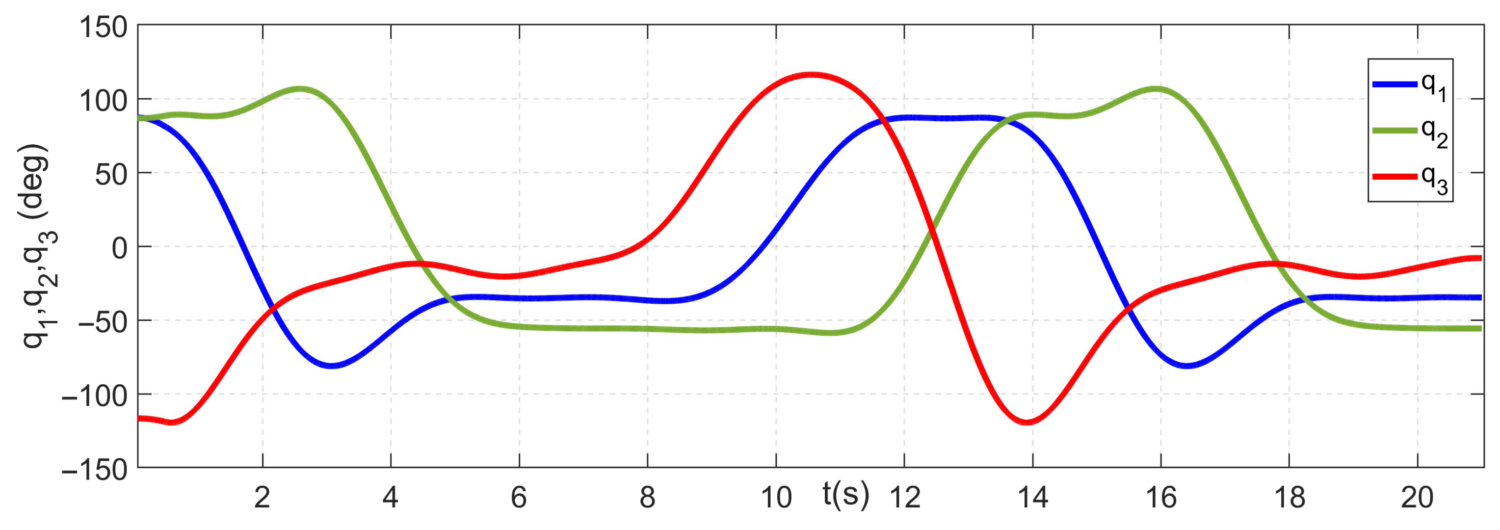
The last phase of the experiment was the implementation of the control based on the obtained dynamic model. A fifth-order polynomial in joint space was used to generate the reference trajectory. The motion of all joints was based on zero, with the motion of the first axis from
with a peak velocity of 53.71
and a peak acceleration of 105.3
, and the motion of the second and third axes from
with a peak velocity of 107.43
and a peak acceleration of 210.6
. The resulting motion corresponds to the “folding” and “unfolding” of the robotic manipulator, and the trajectory was designed purely for test control purposes, so that the axes interact.
Figure 9 demonstrates the desired trajectories for each joint.
To compare the control results based on the obtained dynamic model, the arm was first controlled using decentralised cascade control, similarly to the identification experiment, and the control deviation at each joint was measured. The individual loops of the cascade control were first tuned using the default autotuning procedure implemented by the control system manufacturer.
Table 2 demonstrates the individual controller gains obtained by the autotuning procedure.
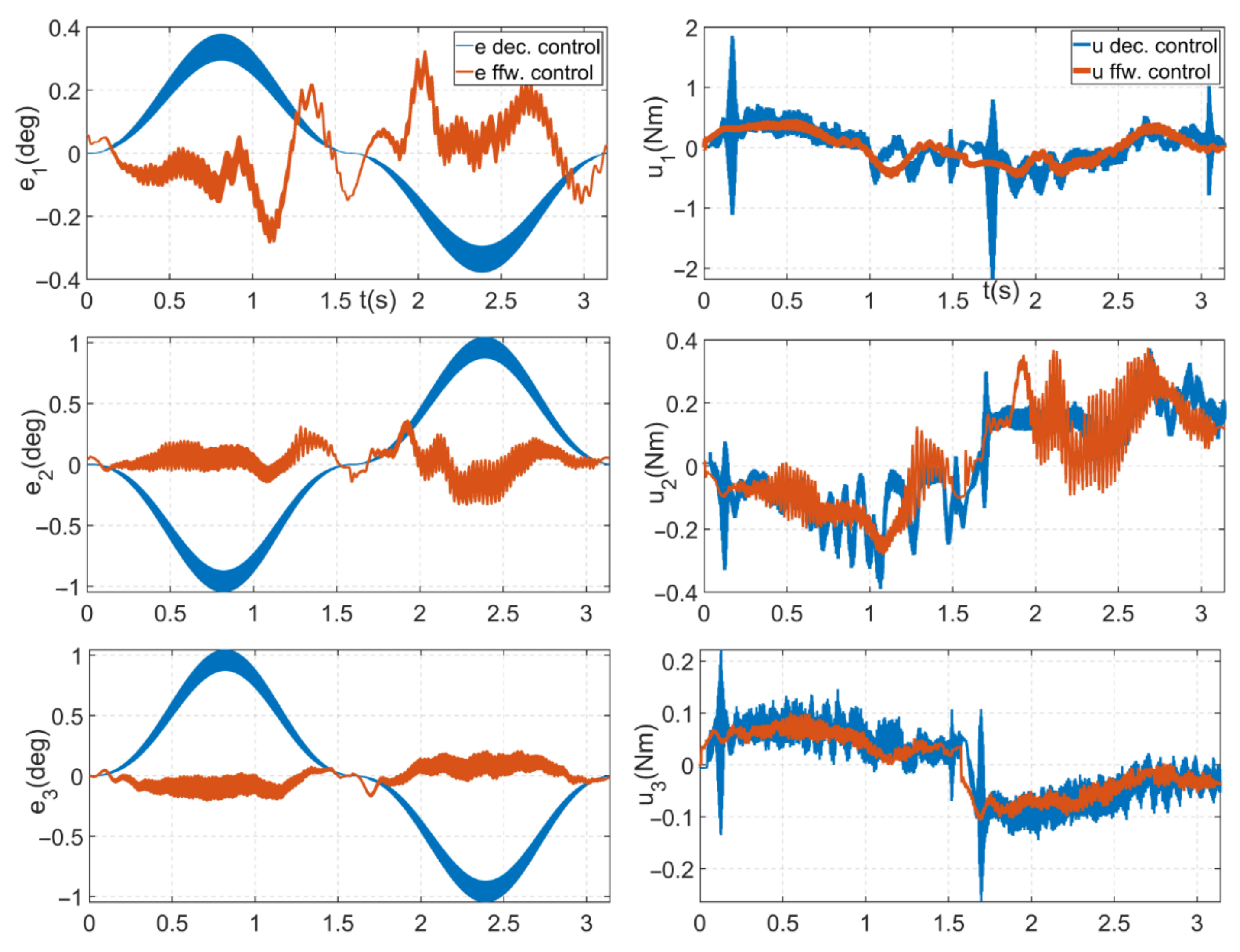
Subsequently, the implementation of the proposed feed-forward control was implemented, where an action intervention in the form of a desired torque was cyclically generated with a period of 400 s.
Figure 10 compares the trajectory error between the decentralised control and the implemented feed-forward control based on the dynamic model. The feed-forward controller reduced the trajectory errors significantly for joints 2 and 3, with peak errors of only 0.36
and 0.2271
, respectively. For joint 1, the tracking errors were similar, but the feed-forward controller had a lower control action.
6. First Generation Robotic Platform
The first generation of the robotic platform was enhanced with a number of components, peripherals, and functions compared to the zero generation platform. The platform was designed to enable testing of both the printing itself and key aspects for fully automated printing such as localisation, self-levelling, and calibration of the printing robot, along with the ability to deploy advanced control methods to achieve the best possible printing accuracy. The platform is currently being deployed and tested on an experimental print arm at a scale of 1:2 against the final print arm.
6.1. Experimental Printing Arm
The experimental print arm is based on the SCARA structure with an added rotational axis and has an identical kinematic structure to the final print arm. As can be seen in
Figure 11, the arm itself has four degrees of freedom and its kinematic structure consists of three consecutive rotational axes (a1–a3) and a final translational axis (a4). The length of the arm is 2.8 m, the vertical stroke of the endpoint is 1 m, and the maximum load on the endpoint is 35 kg. The individual members of the arm have been designed using a generative design to achieve maximum rigidity at a relatively low weight and are made from aluminium alloy using CNC chip machining technology. The arm is mounted on a base which is fitted with four lifting columns (T0–T3) with a maximum lift of up to 2.5 m.
6.2. Final Control System of the Printing Robot
The entire control system of the first-generation robotic platform is in the form of a distributed control system and is divided into four control cabinets (HR1, HR2, PR1, and PR2), which are interconnected by the POWERLINK industrial bus (PLK). The robotic platform is driven by a total of eight drives: four drives for the print arm itself and four drives for the robotic base. The individual enclosures contain the control components for the individual drives. The translational axes are driven by synchronous servo motors from B&R, which ensure very precise positioning. The arm rotary axes are driven by high-end synchronous servo motors with harmonic gears from Harmonics Drive to achieve a chatter-free linkage. The system is also ready for expansion with extruder and tangential axis drives. The extruder axis will be used to extrude the printing compound—a cement mixture—from the print head. The tangential axis represents an additional possible axis for the possibility of rotating the print nozzle in order to rotate it in line with the direction of nozzle movement for the possibility of testing different nozzle shapes.
As already outlined in the subchapter
Section 3.5 the control system includes a very powerful control PC and four servo drivers with the possibility of controlling up to 12 axes, while the servo driver for rotary axis control is extended with SafeMotion functionality based on openSafety technology. This solution allows integrated safety features such as safe speed limiting to be activated to achieve maximum safety for the operator of the print robot. The control system is complemented by a large and robust HMI for the ability to control the robot platform.
6.3. Added Peripherals
The control system is constructed with new peripherals in the form of tilt meters and lidar for the ability to test the self-levelling of the robot base and to solve print arm localisation tasks. The experimental print arm is equipped with four inclinometers from Sick to compensate for unevenness and deviations from the print plane. As can be seen in
Figure 11, the main inclinometer, labelled IN1, is located in the robot table plane. It can measure tilt in three
x,
y,
z axes and can be used to level the table with the environment. The other inclinometers, marked IN2, IN3, and IN4, are located directly on the robot arm structure. IN2 and IN3 are inclinometers with the ability to measure tilt in two
x,
y axes and are used to measure any deflection of the lidar (LD) and the end link of the arm (a3). The last inclinometer, IN4, is also tri-axial and is prepared for the case of extending the robot with a tangential axis; its output can give information about the rotation of the tangential axis on which a print head can be placed. Another peripheral is a 2D lidar from SICK, model SICK NAV350 (SICK AG, Baden-Wuerttemberg, Deutschland). LD lidar is used here for endpoint localisation and guidance capabilities.
6.4. Commissioning and Testing of the First Generation Robotic Platform and Printing Ideas
The first generation robotic platform is currently being commissioned and tested. Before actual deployment for 3D printing applications, a number of tasks need to be resolved such as calibration of the robotic arm, tuning of the individual actuator controllers to eliminate endpoint vibration, testing of localisation concepts, etc.
In order to be able to track the endpoint of the print arm along the desired print trajectory, the robot was equipped with an Ortur 10W LU2-10A laser module (Ortur Intelligent Technologies Co., Ltd, Dongguan, China), which is used in engraving machines. The module features dual-compression diode technology, which is based on the interference of the light beam from two laser diodes. Thanks to this solution, it is possible to test the repeatability and accuracy of the robot’s endpoint, along with the possibility of monitoring the vibration of the endpoint, which is clearly visible in the “engraved waveforms”. With this solution, we can take all factors into account when designing advanced control methods for the robotic arm. An example of the testing can be seen in the video, see
Figure 12, where the robot “engraves” one of the experimental print trajectories in the form of an 800 × 400 mm experimental wall element.
The robotic arm is designed for a so-called sequential printing application, in which the printing robot moves around the site and sequentially prints building structures, or parts of building structures, within its workspace. The robot can be moved either by crane or by its own mobile platform. The key issue in fully automating the sequential printing process is the localisation of the printing machine on the job site, for which the aforementioned lidar will be used.
The actual printing by the robot takes place in individual layers determined by the printing material and in steps dependent on the printing height of the object to be printed. The change of the print head height by one printed layer is realised by the last translation axis of the robot. When the robot reaches the maximum printing height of one step, the robot base is lifted by the extension columns by a predefined distance and the robot can print the next layer. The drives of the extendable columns of the robotic base are engaged between the pieces by an electronic shaft for synchronous movement and to maintain the horizontal position of the robotic base. At the beginning of printing, the individual legs can be positioned independently to compensate for surface irregularities. Thanks to the inclinometers used, this step can be carried out automatically with automatic levelling of the robot base. An example of the robot base lift test can be seen in the video, see
Figure 13, where the robot base is lifted by a defined test height of 1800 mm.
7. Discussion
According to the research conducted, there are many applications dealing with 3D concrete printing technology using robots, but very little attention is paid to the design of robotic arms and their control that would be optimal for this technology. Our solution is unique due to the use of a unique open control printing robot, which, due to its kinematic design and the control used, aims to significantly save the energy consumed in printing buildings. It is the energy consumption of the printing robot that is a key factor in terms of the sustainability of this technology.
Our printing robot is based on an SCARA structure with the addition of a rotating link and thus represents a redundant robot that is generally more complex to control. However, the complexity of the control is compensated for by the much better manipulability of the robot (possibility to print behind already printed objects) and especially by the possibility to conserve kinetic energy when printing a break in the printed curve (not having to stop the whole robot, but only its end point), which leads to energy savings.
The use of a serial kinematic robot structure with rotary linkages is advantageous for the field of 3D printing of buildings, especially because of its compactness and significantly lower weight, e.g., compared to the commonly used gantry robots. The compactness and low weight allows good transportability of the robot arm, both when moving the robot itself on the construction site and when bringing the robot to the construction site. Another significant advantage is the better resistance of the rotary linkages to the dusty environment that is common on construction sites compared to the translational linkages of gantry robots.
Of course, the use of serial robot kinematics with rotary linkages can also bring some disadvantages in terms of problematic endpoint stabilisation. This is due to the vibrations that can arise due to the dynamics of a long-length manipulator movement and pose a significant challenge to the control of such an arm.
For these reasons, testing of advanced control methods for printing robots with special kinematics, which our control system enables, is necessary.
In this paper, an open PLC-based control system for a printing robot is presented, which, thanks to its openness and the technologies used, should allow simple and time-efficient deployment of custom control algorithms. Compared to the PLC-based robotic arm control systems mentioned in the research part of the paper, the presented control system has an openness, which is achieved by using an automatic code generator. This solution allows to cover all the necessary steps from modelling, design, and simulation to the actual implementation of the control in a single environment, thus significantly simplifying and speeding up the time required for prototyping the designed control.
A real-time torque control system was designed and implemented that allows direct torque control of the robot with sampling up to 2.5 kHz, enabling significantly faster action interventions than those offered by commercially available research robotic arms. For example, Franka Emika offers a research robotic system that has an interface that enables torque control with a sampling of 1 kHz. Similarly, the fast research interface (FRI) used in KUKA lightweight robots is limited to 1 kHz sampling [
45,
46].
The advantage of the presented open control system, compared to the mentioned open control platforms of research robotic arms, is that it can suitably represent the behaviour of industrial robotic manipulators due to the industrial control system components used. Thus, the investigated control methods can also be tested in terms of aspects manifested in industrial robotic manipulators that may not be manifested in experimental research arms (e.g., significant change in moments of inertia, vibration of mechanical parts, etc.).
The openness of the control system was tested on the task of implementing model-based control for an experimental model of the printing robot. The whole process, from mathematical modelling, identification of inertial parameters, and design and implementation of the control to actual data processing and analysis, was realised thanks to an open control system in a unified Matlab/Simulink environment. To demonstrate the control implementation, a simple feed-forward control was designed, which achieved significantly better results compared to decentralised control. As a complement, it should be noted that in all conditions in
Figure 10, high frequency vibration is evident, which could result in a reduction in printing accuracy if deployed on a large printing robot. This component can be eliminated by tuning the current control in the cascade controller of the servo driver used by using suitable filters with an appropriate frequency to eliminate this vibration. However, the aim of our demonstration was not to achieve the best possible control, but to demonstrate the advantage of an open system allowing a relatively quick and easy implementation of model-based control.
The purpose of testing was mainly to verify the readiness of the open control platform for deployment on the final printing robot and to evaluate the complexity of the control implementation. The platform is ready for deployment on the final printing robot and for possible testing of more advanced control algorithms to address issues that will become apparent during the 3D printing process by the final printing robot.
8. Conclusions
This paper presents an open PLC-based control system for a unique printing robot. The control system is designed to both enable easy integration of the printing robot into the production process and easy operation by trained workers/operators and to be a suitable test bed for on-site 3D printing technology for buildings. For these purposes, it is equipped with various sensors enabling the determination and testing of key aspects for the full automation of 3D printing in building construction. In addition, emphasis was placed on the openness of the control system to allow testing of advanced control methods suitable for the unique printing robot, which was designed to be as optimal as possible for 3D printing technology. Due to its openness, the control system allows for fast and direct low-level bi-directional communication with the robot arm. The robotic arm can thus be operated even with low-level control or position, speed, and torque control with 2.5 kHz sampling, making it a suitable test bed for academic and development workers. Future work will consist of the deployment of the tested open control system platform in concrete 3D printing technology and in the design and implementation of advanced methods of controlling the printing robot according to the needs of the 3D printing application of buildings.


