Article

Inverse Kinematic Solver Based on Bat Algorithm for Robotic Arm Path Planning

1
Ecole National Sup d’ingénieurs de Tunis, University of Tunis, Tunis 1008, Tunisia
2
Institut Sup des Sciences Appliqués et de Technologie de Sousse, Université de Sousse, Sousse 4003, Tunisia
3
Research Group on Intelligent Machines, Regim-Lab, University of Sfax, BP 1173, Sfax 3038, Tunisia
4
College of Engineering and Technology, American University of Middle East, Egaila 54200, Kuwait
*
Authors to whom correspondence should be addressed.
Robotics 2023, 12(2), 38; https://doi.org/10.3390/robotics12020038
Submission received: 14 January 2023 / Revised: 28 February 2023 / Accepted: 7 March 2023 / Published: 9 March 2023

Abstract

:
The bat algorithm (BA) is a nature inspired algorithm which is mimicking the bio-sensing characteristics of bats, known as echolocation. This paper suggests a Bat-based meta-heuristic for the inverse kinematics problem of a robotic arm. An intrinsically modified BA is proposed to find an inverse kinematics (IK) solution, respecting a minimum variation of the joints’ elongation from the initial configuration of the robot manipulator to the proposed new pause position. The proposed method is called IK-BA, it stands for a specific bat algorithm dedicated to robotic-arms’ inverse geometric solution, and where the elongation control mechanism is embedded in bat agents update equations. Performances analysis and comparatives to related state of art meta-heuristics solvers showed the effectiveness of the proposed IK bat solver for single point IK planning as well as for geometric path planning, which may have several industrial applications. IK-BA was also applied to a real robotic arm with a spherical wrist as a proof of concept and pertinence of the proposed approach.

1. Introduction

Robotic manipulators are characterized by their versatility due to means of their mechanical structure that consists of serial links joined together to be like a human arm, where the motion of their end-effector is dependent on joint movements [1]. This grants them the adaptability to perform in multiple processes, from simple applications such as pick and place operations, to more complex processes that involve applications such as welding, assembly, and painting [2]. These tasks typically require adequate paths to be tracked by the robot’s end-effector [3,4]. These paths are generally described in the Cartesian space, while the end-effector position is set according to the robot joint angles. Therefore, the key issue in path tracking is the mapping between the Cartesian space of the tracked path and the joint space of the robot manipulator. Such mapping is achieved through a kinematic modeling of the robotic arm, where a forward kinematics (FK) model allows determining of the end-effector location from a specific configuration of the robot joints. The FK problem possesses a unique solution, considering that each position of the robot joints drives to a one single location of the end-effector. A common way of solving the FK problem is to use the Denavit-Hartenberg notation [5]; whereas, the inverse kinematics (IK) intends the opposite, i.e., determine the corresponding joint variables that enables the end-effector to reach a specific target position [6]. Figure 1 interprets the relation between the forward and inverse kinematics.
Unlike FK, the IK problem often has many different solutions, since one target point could be reached through multiple positions of the manipulator. Hence, solving the IK problem for robotic manipulators is a challenging task. The geometry of the robot and the nonlinear trigonometric equations that define the mapping between Cartesian space and joint space contribute to the problem’s complexity [7,8]. This problem has been approached by several conventional methods with deterministic characteristics, where their final solution is determined by the initial conditions of the problem [9]. For robots with high degrees of freedom (DOF), the IK problem is more sophisticated, hence, conventional methods require more computational processes, which slow down controlling the manipulator in real time [6,10].
Conventional methods are generally divided into algebraic, geometric, and numerical methods. Algebraic and geometric methods aim to find closed-form solutions to the problem. While they are indeed faster than numerical methods, their provided solutions are not generic but rather robot-dependent. Meanwhile the numerical methods are applicable to any kinematic structure, therefore they are not robot-dependent; however, they are generally time consuming and unable to calculate all possible solutions [11].
With the expansive usage of robot manipulators in production lines, and the prerequisite for higher productivity with high accuracy, many researchers have directed their efforts in searching for alternative approaches that tackle the IK problem while overcoming the disadvantages of conventional methods. The application of artificial neural networks (ANN) is an example of advanced investigations [12,13]. Cursi et al. [14] proposed the use of a type of ANN known as a probabilistic neural network to enhance the task accuracy of a surgical macro–micro robot manipulator. However, using ANNs suffers from long training time and lack of accuracy [15], which has motivated further investigations using other soft-computing alternatives, such as meta-heuristic (MH) algorithms. MH algorithms are characterized by non-deterministic behavior, which eases the obtaining of approximate satisfying solutions of an optimization problem with a plausible computational cost [16,17]. They are exploited to tackle the IK problem using only the FK model. Applying MH algorithms requires modeling the IK problem as an optimization problem [18], where an objective function is defined according to the manipulator’s FK model and the desired pose of the robot’s end-effector. The MH algorithm is dedicated to find the corresponding joints values that enable the robot manipulator to achieve a desired pose. In a case where the objective function is intractable or impossible to be formulated analytically, it is preferable to employ a black-box optimization approach. In this approach, a close form of the objective function is not required [19]. For instance, Cursi et al. [20] developed an open source global optimization framework for robot design. Considering that the robot design is regarded as an optimization problem with a black-box cost function; therefore, their developed framework implements a Bayesian optimization method to approximate an appropriate formulation of the objective function.
This paper suggests a sensible adjustment of a MH algorithm, known as the bat algorithm (BA) for the IK problem, IK-BA, of robot manipulators with spherical wrists, which is typical for industrial robotic arms. The main motivation of the use of the MH approach for open chain robotic arm is to avoid the singularities of the classical invers solvers. Singularities consist in configurations where the inverse kinematic equations of the robotic arm do not have a unique solution [21]. Classical IK solvers may not provide a meaningful solution at singular configurations, since the Jacobian matrix becomes singular, which means that it cannot be inverted to calculate the required joint velocities [22]. By using MH optimization approaches as IK solvers, the robotic arm can avoid these singularities by exploring alternative configurations and selecting the optimal solution based on a predefined fitness function. This approach can help to improve the overall performance and reliability of the robotic arm, allowing it to carry out complex tasks with greater accuracy and efficiency [23].
The proposed IK-BA is an intrinsically hybridization of BA, which aims to accord an IK solution, while assuring a minimal variation from the initial configuration of the robot manipulator until the solution’s position. The elongation control mechanism is embedded within BA update equations, making the proposal specific to IK. This contraction between the initial configuration and the generated solution, guarantees a shorter path compared to another IK solution provided without considering the initial configuration. The adjustment of the BA algorithm lies in modifying its update equations in a way to generate solutions affected by the initial configuration. The remaining of the paper is organized as follows: paragraph 2 details the key related works and similar proposals; paragraph 3 stands for the IK problem statements with elongation control. In paragraph 4, the BA algorithm is presented before introducing the IK-BA proposal, it ends with a flowchart describing how a path planning can be conducted using the suggested method. An experimental investigation is presented in paragraph 5, including a comparative analysis and a time assessment test, based on an industrial robotic arm. Conclusion and discussions are detailed in paragraph 6.

2. Related Works

Early applications of meta-heuristic algorithms for solving the IK problem for redundant robotic manipulators have emanated from using one of the initial paradigms of MH algorithms, which is the genetic algorithm (GA). The GA is an MH developed by Holland [24]. It is inspired by the process of natural selection and evolution, which is used to find approximate solutions to optimization and search problems. Genetic algorithms are commonly used in a variety of fields, including machine learning, engineering, to solve complex optimization problems that are difficult to solve using traditional methods [25].
Parker et al. [26] tested the GA in solving the IK problem of a 4 DOF serial manipulator, where the solution provides a minimized largest joint displacement in a point-to-point positioning task. Furthermore, Nearchou [27] suggested using a modified version of GA to solve the IK problem as a way to minimize both the end-effector’s positional error and the robot’s joint movements, while keeping the solution free from collisions with obstacles in the robot’s workspace. Both contributions used the weighted sum approach to combine the minimization of the positional error and the minimization of joint motions objectives, into one objective function. Tarokh and Zhang [28] used the same approach with an additional objective function dedicated to the orientation employing an adaptive GA to tackle the trajectory tracking problem of robot manipulator. In the weighted sum approach, a multi-objective optimization problem is transformed into a single objective, where each objective function is multiplied by a user-supplied weight. The weight value assigned to an objective function is generally proportional to the objective’s relative importance. However, the importance of an objective is a vague concept, hence, the choice of these coefficients might be inaccurate, whereas the final solution is strongly affected by the chosen weight coefficients, which eventually might lead to an inaccurate solution [29].
Another paradigm of MH algorithms is the particle swarm optimization (PSO) algorithm. It was developed in 1995 by Kennedy and Eberhart [30]. The PSO is inspired by the social behavior of birds’ flocks and fish schools. It has been applied as an IK solver, as in [31,32,33].
Adly and Abd-El-Hafiz [34] have intended to solve the IK problem with minimizing the range difference between the initial joints position and the IK solution values that represent the final position. They suggested a multi-objective optimization approach, where the first objective function is dedicated for the IK solution; meanwhile, the second function formulates the variation from the initial joint values and the solution values. They applied an extension of PSO for multi-objective optimization problems called the Time Variant Multi-Objective Particle Swarm Optimization (TV-MOPSO) algorithm [35]. This approach provides an IK solution that guaranties an optimal trajectory of the end-effector to move from one point to another. However, compared to the single objective approach, the multi-objective method is generally more time-consuming as it requires additional processes for generating a set of trade-off solutions that satisfies two or more conflicting objectives.
Rokbani et al. [36] proposed a multi-objective version of a new modified particle swarm optimization MO-m-PSO to solve the inverse kinematics of a 5-DOF robotic arm. Its IK problem is formulated as a multi-objective problem that takes into consideration the end-effector pose (position and orientation).
Various other swarm-based meta-heuristics were employed for the IK issue, such as Cuckoo Search Algorithm [37], Artificial Bee Colony [38,39], Firefly Algorithm [40,41], and Salp Swarm Algorithm [42]. Most investigations about the application of MH algorithms to the IK problem proved that MH algorithms are suitable and reliable IK solvers. Accordingly, some researchers have made further analyses attempting to employ MH algorithms for robot manipulator trajectory tracking. Lopez-Franco et al. [43] presented a comparative study on six soft-computing algorithms in solving the IK and path tracking problems, where the best algorithm according to the comparative simulations is applied on a real robot manipulator. Kanagaraj et al. [44] tested the performance of four MHs in path tracking simulations, where the algorithms are required to solve the IK problem for every point of a generated trajectory. The tested algorithms are particle swarm optimization (PSO), whale optimization algorithm (WOA), gravitational search algorithm (GSA), and the bat algorithm (BA). The simulation results confirmed the outperformance of the BA compared to the others.
When robots need to follow a specific orientation with a minimal angles variation during point-to-point tasks, the two most common approaches used are the classical weighted sum technique or multi-objective optimization methods. The weighted sum technique simplifies the problem, but may not be so accurate, while the multi-objective optimization requires more computing time. In this paper, the IK-BA is suggested to solve the IK problem assuring a minimal variation of joint angles (elongation). The proposed method takes into account the initial joint configuration that restricts the exploration of the algorithm, hence guaranteeing a limited variation of angles from the initial configuration towards the final solution. It is tested on solving the IK problem of KUKA LBR iiwa 14 R820 robotic arm; it is compared with ordinary BA, and other MH-IK solvers from the literature. The comparatives are in terms of accuracy and angles variation of their provided IK solutions.

3. Inverse Kinematics Problem

The positional accuracy of a robotic manipulator is assessed by the distance between the desired position to reach and the actual position of the robot’s end-effector, which is mathematically calculated using the following equation:
ε p = ( x x d ) 2 + ( y y d ) 2 + ( z z d ) 2
where ( x , y , z ) ,   ( x d ,   y d ,   z d ) denotes the end-effector’s coordinates and the desired coordinates, respectively. The lower the distance error ε is, the higher the accuracy.
The orientation of the end-effector could be described by a 3 × 3 rotation matrix as represented in Equation (2) below:
R = [ n x o x a x n y o y a y n z o z a z ]
where n = [ n x   n y   n z ] T , o = [ o x   o y   o z ] T and a = [ a x   a y   a z ] T are the expression of x , y and z axes, associated to the end-effector frame, relative to the base frame.
Let R d be required orientation of the end-effector. The orientation error ε r could be defined as in [45] using Equation (3), where . indicates the Euclidean norm of a matrix.
ε r = R R d R d
The IK problem aims to determine the appropriate joint angles that minimize the position error, which could be formulated as an optimization problem as denoted in Equation (4):
Find   Θ   = [ θ 1 , θ 2 , , θ n ]   that : { M i n i m i z e   ε p   a n d   ε r S u b j e c t   t o :   Θ min Θ     Θ max
where Θ is a vector of joint angles of an n-dof robot manipulator. Θ min and Θ max are vectors that represent the upper bound and the lower bound of joint angles, respectively.
Formulating the IK problem as an optimization problem enables the employment of an optimization an algorithm to determine an adequate solution.

4. Proposed Method

4.1. Bat Algorithm

The bat algorithm (BA) is a nature-inspired algorithm, developed by Yang [46]. It is built around the bio-sonar characteristics of micro-bats, known as echolocation. Most bats use echolocation to navigate and catch prey in dark places. Micro-bats are able to emit ultrasonic pulses that bounce as an echo when clashing into a surrounding object. When the echo bounces to their ears, they could estimate the location of the object, based on the delay time between the emitted sound pulse and the echo. Each pulse has a constant frequency in the range of 25 KHz to 150 KHz, and they typically last 5 to 20 ms. Micro-bats emit around 10 to 20 sound pulses every second with a loudness in the range of 110 dB. While they became quieter when hovering close to a prey, the rate of pulses per second could increase to 200.
The BA is formulated based on the principle of echolocation characteristics of micro-bats, when it is associated with an objective function as a subject of optimization.
To numerically simulate the bats behaviour for an optimization problem, each bat is formulated with a set of parameters:
  • Position X : corresponds to the position of the bat in the search space, representing a candidate solution of the optimization problem.
  • Velocity V : is the velocity of the bat, which models an incremental variation of the position between 2 successive iterations.
  • Frequency f : is the frequency of the emitted pulse. It is used to adjust the velocity change.
  • Loudness A : represents the loudness of the emitted pulse. It enables a local search around the best solution.
  • Pulse rate r : is the rate of the emitted pulses. It increases gradually along the iterations of the algorithm, assuming a consistent gradual compromise from an exploration phase to an exploitation phase.
The position X i and velocity V i of bat i are updated in the search space at each iteration t , according to the following equations:
f i = f m i n + ( f m a x f m i n ) β
V i t = V i t 1 + ( X i t X b e s t ) f i
X i t = X i t 1 + V i t
where β   [ 0 , 1 ] is a random generated vector drawn from a uniform distribution. X b e s t is the current best position (solution) among the positions of all bats. Initially each bat is assigned by a random frequency f i uniformly drawn from [ f m i n , f m a x ] using Equation (5).
A local search is performed around the selected best solution, where a new solution is locally generated using random walk using Equation (8):
X n e w = X g b e s t + ε   A t
where ε is random number in the range of [−1, 1] generated from a normal distribution. A t is the loudness at iteration t .
The loudness A decreases progressively while the rate pulse increases along the iterations. This mimics the natural behaviour of bats when they get closer to their prey. This formulated in Equations (9) and (10):
A i t + 1 = α   A i t
r i t + 1 = r i 0 [ 1 e x p ( γ   t ) ]
where α and γ are constants. r i 0 is the initial rate of pulse emission that corresponds to the maximal value r attained when t . According to Equations (9) and (10), for any 0 < α < 1 and γ > 0 , the variation of the loudness A i and the pulse rate r i , along the iterations proceeding is described as below:
A i t 0 ,   r i t   r i 0 ,   as   t
Algorithm 1 is a pseudo code that elucidates the approach of the BA.
Algorithm 1: Pseudo code of BA
Input: Fitness function: f i t ( X = [ x 1 , , x n ] T ) , Number of bats: N , Maximum number of iterations: t m a x , frequency range: f m i n and f m a x , increasing coefficient: α , Attenuation coefficient: γ
Output: Best solution X b e s t
Initialize the bat population  X i ( i = 1 ,   2 ,   ,   N )  and  V i ;
Define pulse frequency  f i  at  x i ;
Initialize pulse rates  r i  and the loudness  A i ;
while  t < t m a x  do
  for  i = 1 : N  do
   Adjust frequency using Equation (5);
   Update velocity and position using Equations (6) and (7), respectively;
   if  r i < r a n d  then // rand is a random number in [0, 1]
    Select a solution among the best solutions  X b e s t ;
    Generate a local solution around the selected best solution using Equation (8);
   End
   evaluate the new solution according to the objective;
   if  r a n d < A i   &   f ( X i ) < f ( X b e s t )  then
    Accept the new solution;
    Increase  r i  and decrease  A i  using Equations (9) and (10);
   End
   Rank the bats according to their fitness and update the best solution  X b e s t ;
  End
End

4.2. Bat Algorithm for Inverse Kinematics

In this study, a simplified version of BA is employed, where the loudness A and the pulse rate r are equivalent for all bats as in [47]; in order to make it easier to implement, reduce the computational complexity for a faster convergence of the algorithm, and to provide a better balance between exploration and exploitation.
The proposed IK-BA ensures a minimum angular variation, which could be measured using Equation (12).
V a r i a t i o n ( Θ s , Θ f ) = | | Θ s Θ f | | = i = 1 d ( Θ s Θ f ) 2
where Θ s = [ θ s 1 ,   θ s 2 , , θ s d ]   and   Θ f = [ θ f 1 ,   θ f 2 , , θ f d ] represent the positions of the initial configuration and solution’s configuration, respectively. d is the the number of DOF of a robot manipulator.
The velocity update equation is modified as in Equation (13), where the initial configuration is included in the equation to restrict the bats positions in the search space according to the initial position.
V i t = V i t 1 + ( X i t ( X b e s t + Θ s ) 2 ) f i
Another modification concerns the local search generated by Equation (8). It is modified to take into account the initial configuration at the expense of the best solution in the last iterations as in Equation (14). Furthermore, the local search acquired by this equation is realized at each iteration; hence, the condition ( r i < r a n d ) in Algorithm 1 is removed in the IK-BA.
X n e w = r t X g b e s t + ( 1 r t ) Θ s + ε   A t
Note that it is preferable to use the initial configuration instead of random positions, as initial position for at least one bat, to assure a minimal angle variation.
For the IK-BA, the bats position vector X = (   [ x 1 , , x n ] T ) corresponds to the joint positions of the robot, where each bat’s position represents a potential solution to the IK problem. The fitness function f i t ( ) denotes the difference between the desired end-effector position and the actual end-effector position, as in Equation (1). f i t ( ) is used to evaluate the quality of the solution X at each iteration of the algorithm. New potential IK solutions are generated iteratively by modifying the current solutions using the echolocation of the bat, which is numerically simulated by the algorithm’s intrinsic parameters f ,   A and r . Algorithm 2 presents the methodology of the proposed IK-BA used in this study.
Algorithm 2: IK-BA pseudo code
Input: IK fitness function: f i t ( X = [ x 1 , , x n ] T ) , Number of bats: N , Maximum number of iterations: t m a x , frequency range: f m i n and f m a x , increasing coefficient: α , Attenuation coefficient: γ , Initial configuration: Θ s = [ θ s 1 ,   θ s 2 , , θ s d ] , Target position: P = [ p x   p y   p z ]
Output: Best solution X b e s t
Initialize the bat population  X i ( i = 1 ,   2 ,   ,   N )  and  V i ;
Define pulse frequency  f i  at  x i ;
Initialize pulse rates  r i  and the loudness  A i ;
while  t < t m a x  do
  Increase  r i  and decrease  A i  using Equations (9) and (10);
  for  i = 1 : N  do
   Adjust frequency using Equation (5);
   Update velocity depending on  Θ s = [ θ s 1 ,   θ s 2 , , θ s d ]  using Equation (13) and the position and using Equation (7);
   Select a solution among the best solutions  X b e s t ;
   Generate a local solution around the selected best solution depending on   Θ s = [ θ s 1 ,   θ s 2 , , θ s d ]  using Equation (14);
   evaluate the new solution according to the fitness function fit(X) and target position  P = [ p x   p y   p z ]
   if  r a n d < A i   &     f ( X i ) < f ( X b e s t )  then
    Accept the new solution;
   end
   Rank the bats according to their fitness and update the best solution  X b e s t ;
  end
end

4.3. IK-BA for Decoupled Position-Orientation

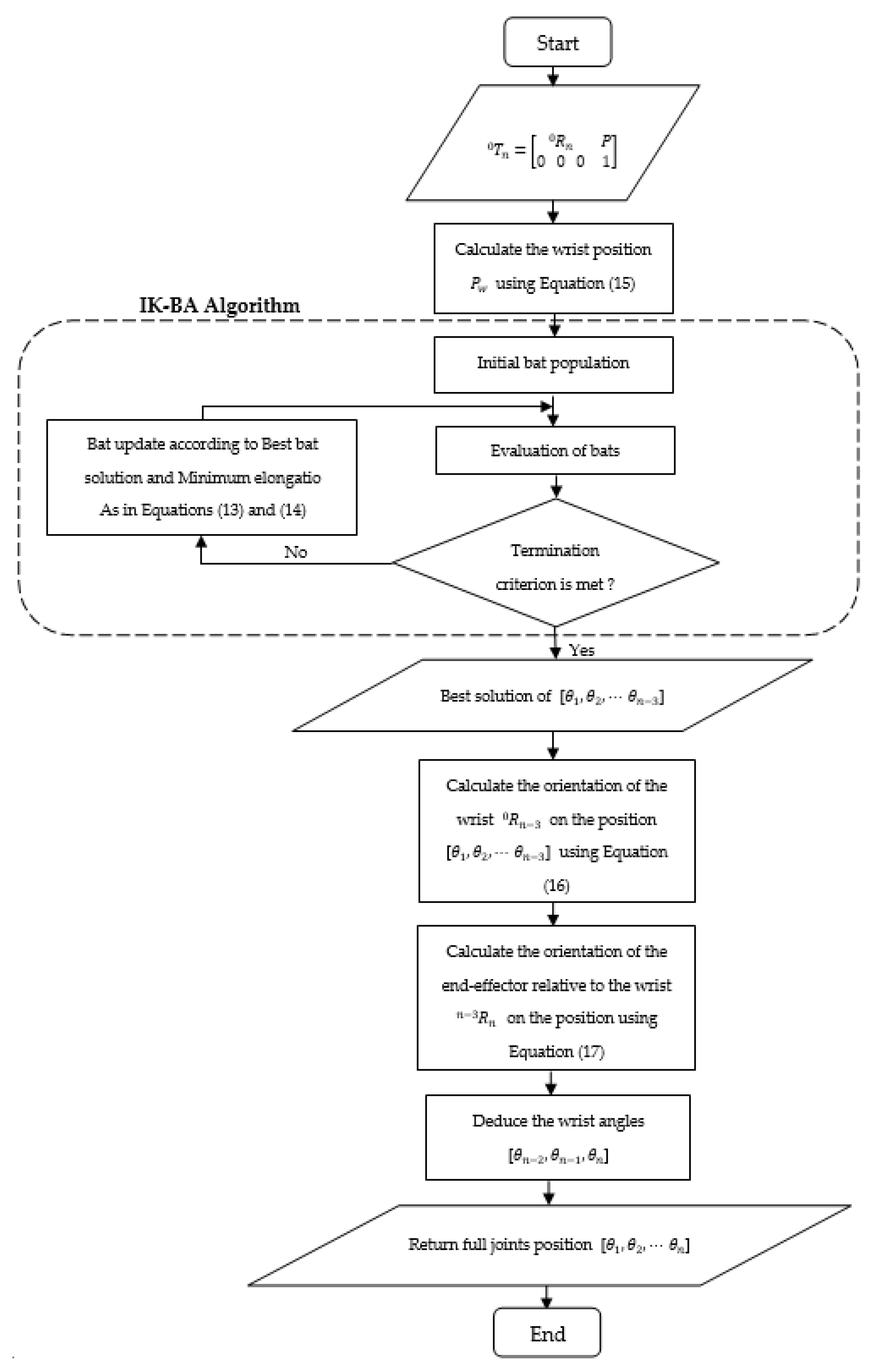
For a robot manipulator of n -dof with spherical wrist, the axes of the last three rotational joints, dedicated to the orientation of the end-effector, intersect in one point. The manipulator can be accordingly decoupled into two parts. The first ( n 3 ) joints are responsible for the position and their values would be determined using the IK-BA, whereas the last three joints would be calculated according to the required orientation. Based on the formulation in [21], the origin of the ( n 2 ) frame O ( n 2 ) (point of intersection of the three last joints, that assign the orientation) defines the wrist’s position of the arm in relation with the end-effector’s position as shown in Figure 2 and formulated in Equation (15):
P w = P d n [ R ] [ 0 0 1 ]  
where, d n is the distance between O n 1 and O n along Z n 1 .   [ R ] is a 3 × 3 rotation matrix of the end-effector relative to the base (frame 0), where its third column indicates the direction of z n and z n 1 axes with respect to the base (since z n and z n 1 are always collinear). P w and P are the vectors denoting the position of the wrist and the position of the end-effector, relative to the base frame.
To include a required orientation in addition to the position, the calculation of the three last joints value using the IK-BA is excluded. In this case, the algorithm attends to finding the values of θ i ,   i = 1 , , n 3 , that enable the wrist to be positioned in P w position, calculated by Equation (15). The remaining angles θ n 2 , θ n 1 and θ n are calculated according to the orientation of the wrist based on the θ i ,   i = 1 , , n 3 values provided by the IK-BA, and the required orientation 0 R n , using Equations (16) and (17):
0 R n 3 ( θ 1 ,   θ 2 ,   ,   θ n 3 ) = R 1 0 ( θ 1   ) × 1 R 2 ( θ 2 ) × × n 4 R n 3 ( θ n 3 )
n 3 R n ( θ n 2 ,   θ n 1 ,   θ n ) = R n 3 ( 1 ) 0 × R n 0
In a robotic arm with a spherical wrist, the orientation of the end-effector is set according to the positions of the last three joints, in which their values could be deduced from the n 3 R n orientation matrix. Thus, all the required values θ i ,   i = 1 , , n to attain a specific pose 0 T n are obtained in two phases. In a first phase, the values of θ i ,   i = 1 , , n 3 are obtained using the proposed IK-BA in order to enable the wrist of the arm to reach the position calculated using Equation (15). Furthermore, in a second phase, the required rotational matrix to reach the desired orientation is calculated using Equations (16) and (17), and the remaining three joints value θ i ,   i = n 2 , , n are deduced from the required rotational matrix.
Figure 3 is a flowchart that summarizes the entire methodology.

5. Simulation Results

The proposed IK-BA is dedicated to providing an IK solution dependent on the initial configuration. The advantage of this approach lies in solving the IK problem while minimizing the joints variation from one point to another. The proposed methodology highlights its importance in path tracking tasks for assuring a smooth variation of the joints values from point to point of the trajectory, hence a path tracking test is suggested to feature this advantage.
The performance of the IK-BA is compared with the ordinary BA, and other MH algorithms from the literature.
The kinematic structure of KUKA LBR iiwa 14 R820 robot manipulator is considered for the path tracking test.

5.1. Kinematic Modeling of the KUKA LBR Iiwa 14 R820

KUKA LBR iiwa 14 R820 is a 7-axes robot manipulator. Its kinematic structure provides it with a maximum versatility that makes it effective in collaborative tasks with human operators. Figure 4 elucidate the allocation of the KUKA LBR’s joints and their associated frames. The intrinsic parameters of the algorithms used in the simulation are indicated in Table 1.
In the Denavit–Hartenberg notation, each link relating two neighbouring joints j 1 and j is described by 4 parameters, whereas each parameter denotes a spatial transformation between the frames associated to each joint. These parameters are:
  • θ i : indicates a rotational transformation from frame j 1 to frame j around the z axis, therefore θ j is the angle between x j 1 and x j through z j 1 .
  • d j : indicates a displacement from frame j 1 to frame j along the z axis, it is measured as the distance from o j 1 to x j along the z j 1 .
  • a j : indicates a displacement from frame j 1 to frame j along the new x axis, therefore it represents the distance between z j 1 and z j axes along x j .
  • α j : indicates a rotational movement from frame j 1 to the frame j around the new z axis, therefore α j is the angle between from z j 1 to z j axes about the x j axis.
The pose (orientation and position) of frame j relative to j 1 , could be defined by a 4 × 4 homogeneous matrix, that corresponds to the product of the four transformations denoted by ( θ i , d j , a j and α j ) as implied in Equation (18):
T j j 1 = R o t z , θ j · T r a n s z , d j · T r a n s x , a j · R o t x , α j = [ C ( θ j ) S ( θ j ) 0 0 S ( θ j ) C ( θ j ) 0 0 0 0 1 0 0 0 0 1 ] · [ 1 0 0 0 0 1 0 0 0 0 1 d j 0 0 0 1 ] · [ 1 0 0 a i 0 1 0 0 0 0 1 0 0 0 0 1 ] · [ 1 0 0 0 0 C ( α j ) S ( α j ) 0 0 S ( α j ) C ( α j ) 0 0 0 0 1 ] = [ C ( θ j ) S ( θ j ) C ( α j ) S ( θ j ) S ( α j ) a i C ( θ j ) S ( θ j ) C ( θ j ) C ( α j ) C ( θ j ) C ( α j ) a i S ( θ j ) 0 S ( α j ) C ( α j ) d j 0 0 0 1 ]
Matrix T j j 1 represents the transformation matrix from frame j 1 to frame j . C ( ) and S ( ) stands for c o s ( ) and s i n ( ) functions respectively.
Table 2 represents the DH parameters of the KUKA LBR iiwa 14 R820 robot manipulator according to Figure 4.
Based on the generic homogeneous matrix of Equation (18) and the DH parameters in Table 2, the last column in the table indicates the limits of each joint. The transformation matrix between each two successive joints of KUKA LBR iiwa 18 R820 are denoted from Equations (19)–(25).
T 1 0 = [ C ( θ 1 ) 0 S ( θ 1 ) 0 S ( θ 1 ) 0 C ( θ 1 ) 0 0 1 0 d 1 0 0 0 1 ]
T 2 1 = [ C ( θ 2 ) 0 S ( θ 2 ) 0 S ( θ 2 ) 0 C ( θ 2 ) 0 0 1 0 0 0 0 0 1 ]
T 3 2 = [ C ( θ 3 ) 0 S ( θ 3 ) 0 S ( θ 3 ) 0 C ( θ 3 ) 0 0 1 0 d 3 0 0 0 1 ]
T 4 3 = [ C ( θ 4 ) 0 S ( θ 4 ) 0 S ( θ 4 ) 0 C ( θ 4 ) 0 0 1 0 d 4 0 0 0 1 ]
T 5 4 = [ C ( θ 5 ) 0 S ( θ 5 ) 0 S ( θ 5 ) 0 C ( θ 5 ) 0 0 1 0 d 5 0 0 0 1 ]
T 6 5 = [ C ( θ 6 ) 0 S ( θ 6 ) 0 S ( θ 6 ) 0 C ( θ 6 ) 0 0 1 0 0 0 0 0 1 ]
T 7 6 = [ C ( θ 7 ) S ( θ 7 ) 0 0 S ( θ 7 ) C ( θ 7 ) 0 0 0 0 1 d 7 0 0 0 1 ]
The representation of the end-effector’s pose relative to the base frame is obtained through a successive multiplication of transformation matrices between two adjacent joint frames, as denoted in Equation (26).
T 7 0 = T 1 0 · T 2 1 · T 3 2 · T 4 3 · T 5 4 · T 6 5 · T 7 6 = [ n x o x a x p x n y o y a y p y n z o z a z p z 0 0 0 1 ]
where n = [ n x   n y   n z ] T , o = [ o x   o y   o z ] T and a = [ a x   a y   a z ] T are the elements of rotational transformation matrix, that describe the orientation of the end-effector in reference to the base frame (frame 0). p x ,   p y and p z that indicates the coordinates of the end-effector’s position along the x 0 , y 0 , z 0 axes.
Each set of values of these angles θ i ,   i = 1 , , 7 results in a unique pose defined by T 7 0 . In the case of redundant robot manipulators where the number of degree of freedom is higher than the sufficient end-effector’s active joints for a certain task [50], a particular position of the end-effector might be reached through multiple different configurations of the manipulator. Unlike the forward kinematics problem, the inverse kinematics problem has infinite solutions.
The IK-BA is used in this study to determine the corresponding joint values θ i ,   i = 1 ,   ,   7 that enable the end-effector to reach a desired pose defined by T 7 0 , along with granting a minimal possible joints displacement from an initial configuration to the target pose, using the proposed IK-BA.

5.2. Path Tracking Test

The path tracking test is proposed to evaluate the performance of the algorithm in solving the IK problem for each point along a trajectory. The efficiency of the IK-BA in terms of the accuracy of the solution and angles variation from point to point within the track, is compared with the ordinary BA, Differential Evolution (DE), PSO, K-ABC and Multi Objective PSO, and MO-PSO algorithm, which tackles the IK problem as a multi-objective optimization problem, where the algorithm aims to minimize the positional error and the angles variation simultaneously, as in [34].
The proposed path for this test, consists of 20 points distributed along a helical track within the workspace of the KUKA LBR iiwa 14 R820 as shown in Figure 5. The helical trajectory is defined by its center point from the bottom C = [ x c = 60   cm ,   y c = 0   cm ,   z c = 10   cm ] relative to the base of the robot, a radius of the helix r = 20   cm , its length l = 50 cm, and a number of helices h = 2. In this test, the required orientation of the robot’s end-effector during the path tracking process is defined by Equation (27), which enables the end-effector to be normal to the base floor.
R 7 0 = [ 1 0 0 0 0 1 0 1 0 ]
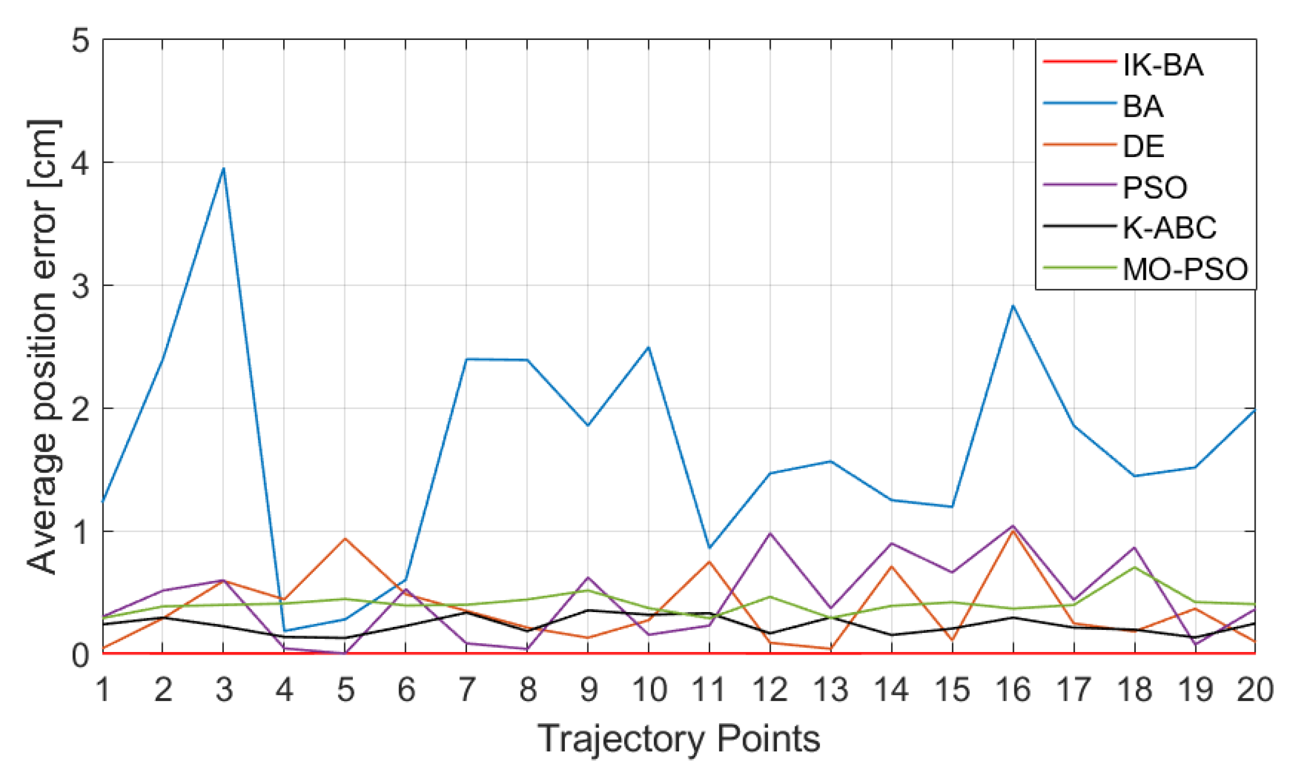
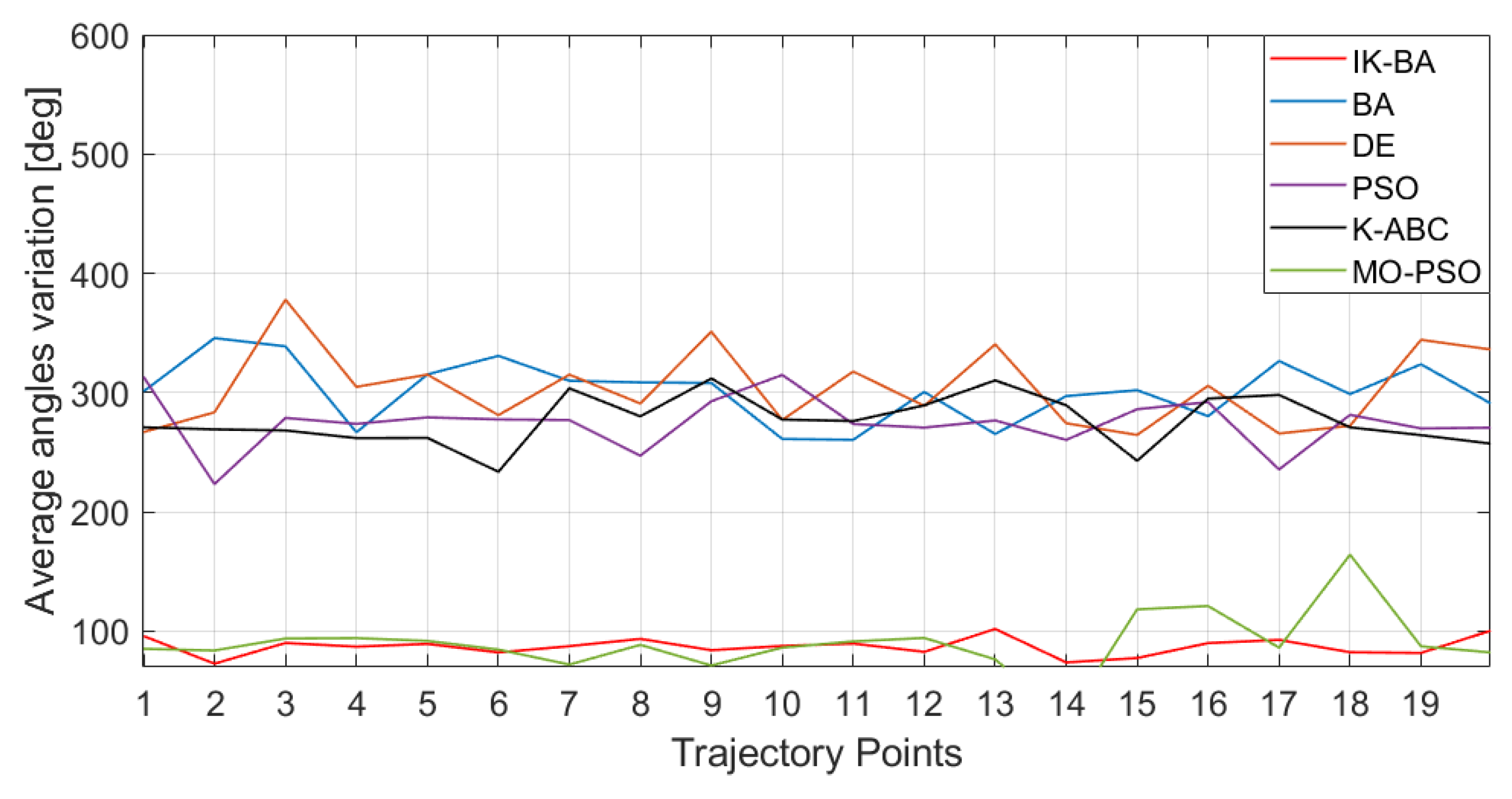
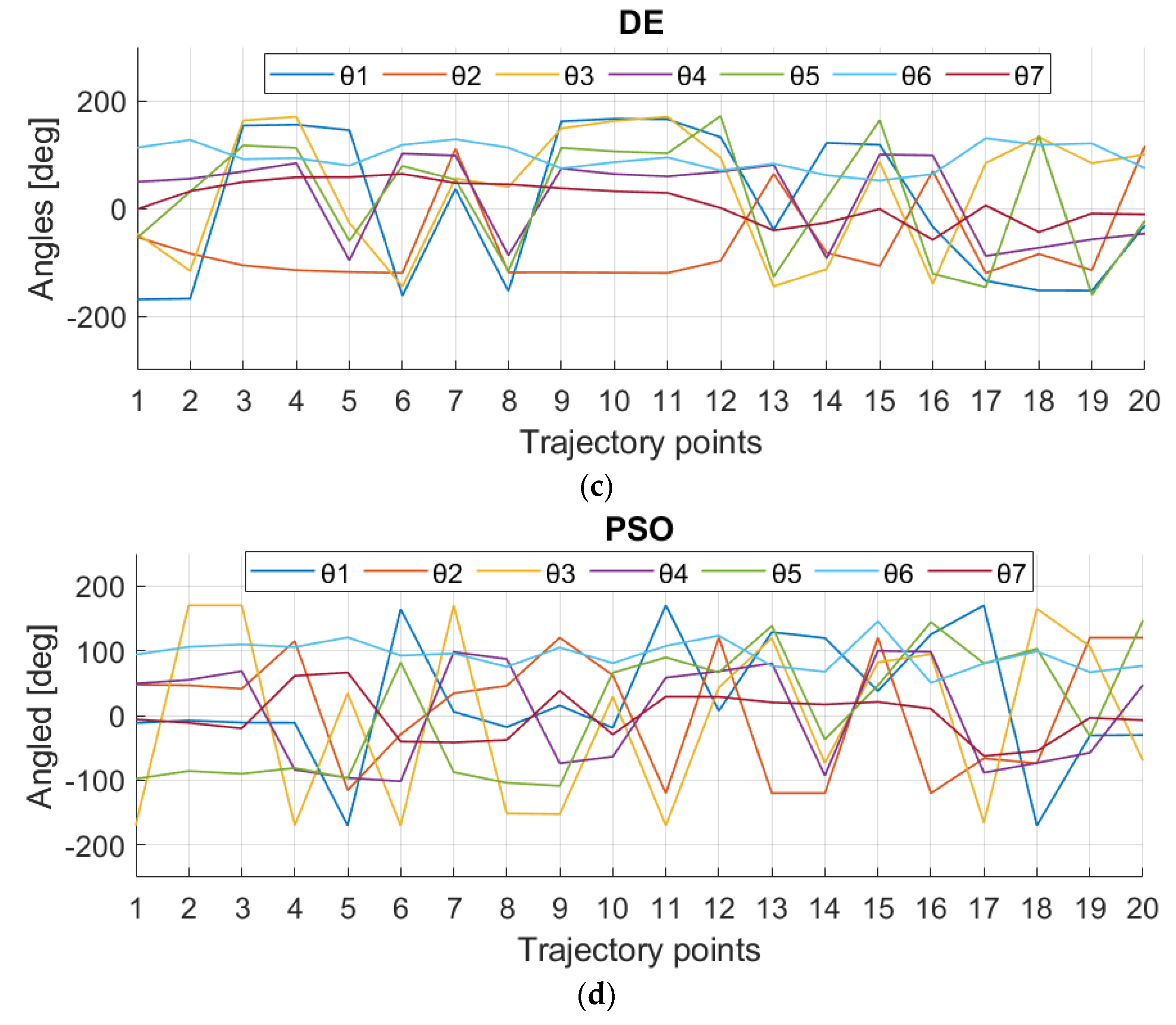
The common parameters for all the compared algorithms used in this test are population size N = 50 , and the maximum number of iterations t m a x = 200 . For reliability inception, the path tracking test is run 20 times and the average position error, angles variation and the computing taken time of the IK solution for each point of the trajectory is recorded as evaluation’s criteria of the performance of the IK-BA in comparison with the other algorithms, in path tracking task. Figure 6 shows the average error of the IK solutions for each point. Figure 7 displays the angles variation from point to point of the trajectory, noting that the angles variation of the 1st point is relative to the initial configuration of the robot. Figure 8 reveals the average calculation time taken to provide an IK solution for each point of the trajectory. Figure 9 represents the joints movement along the trajectory of the first run of the path tracking test.
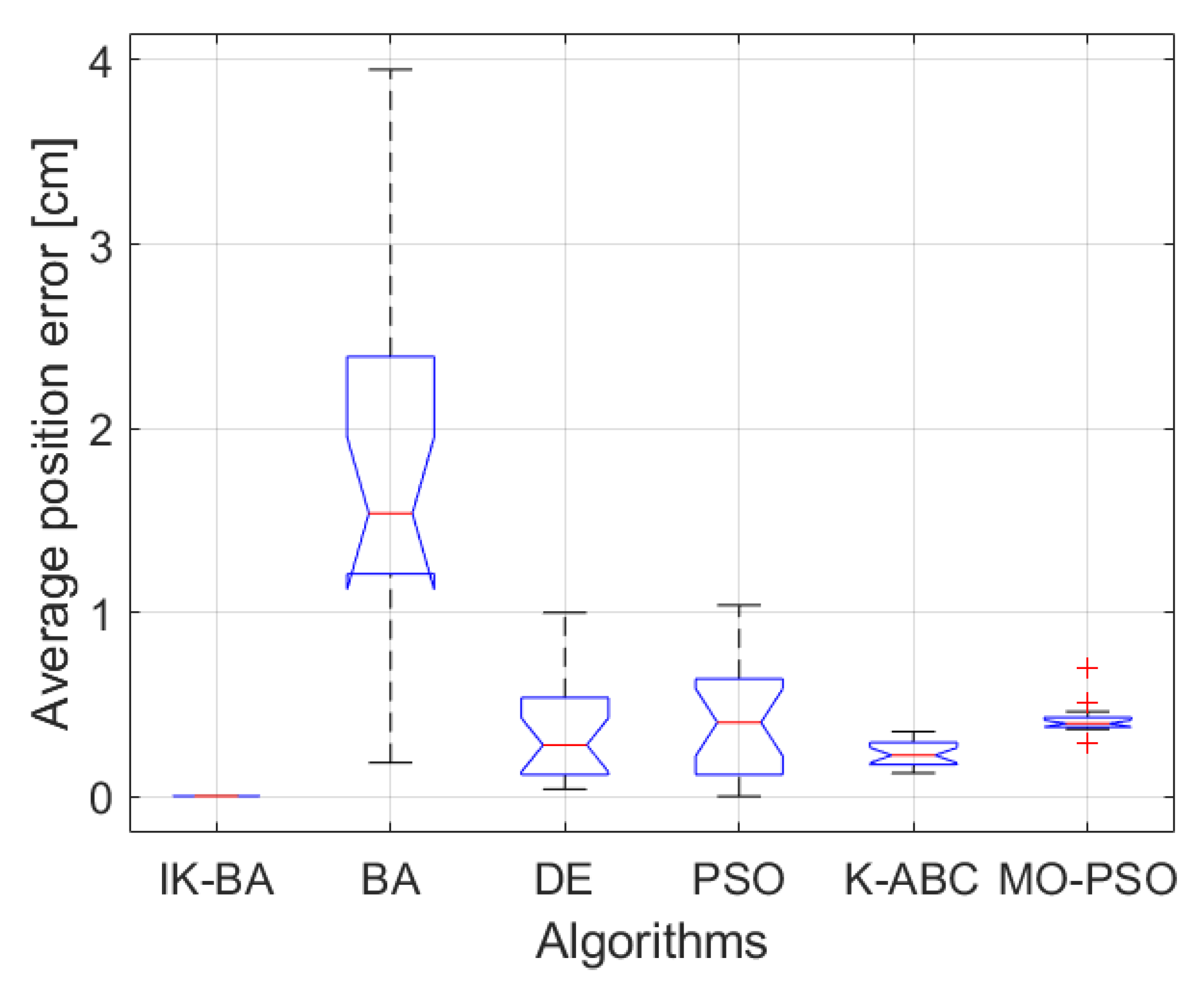
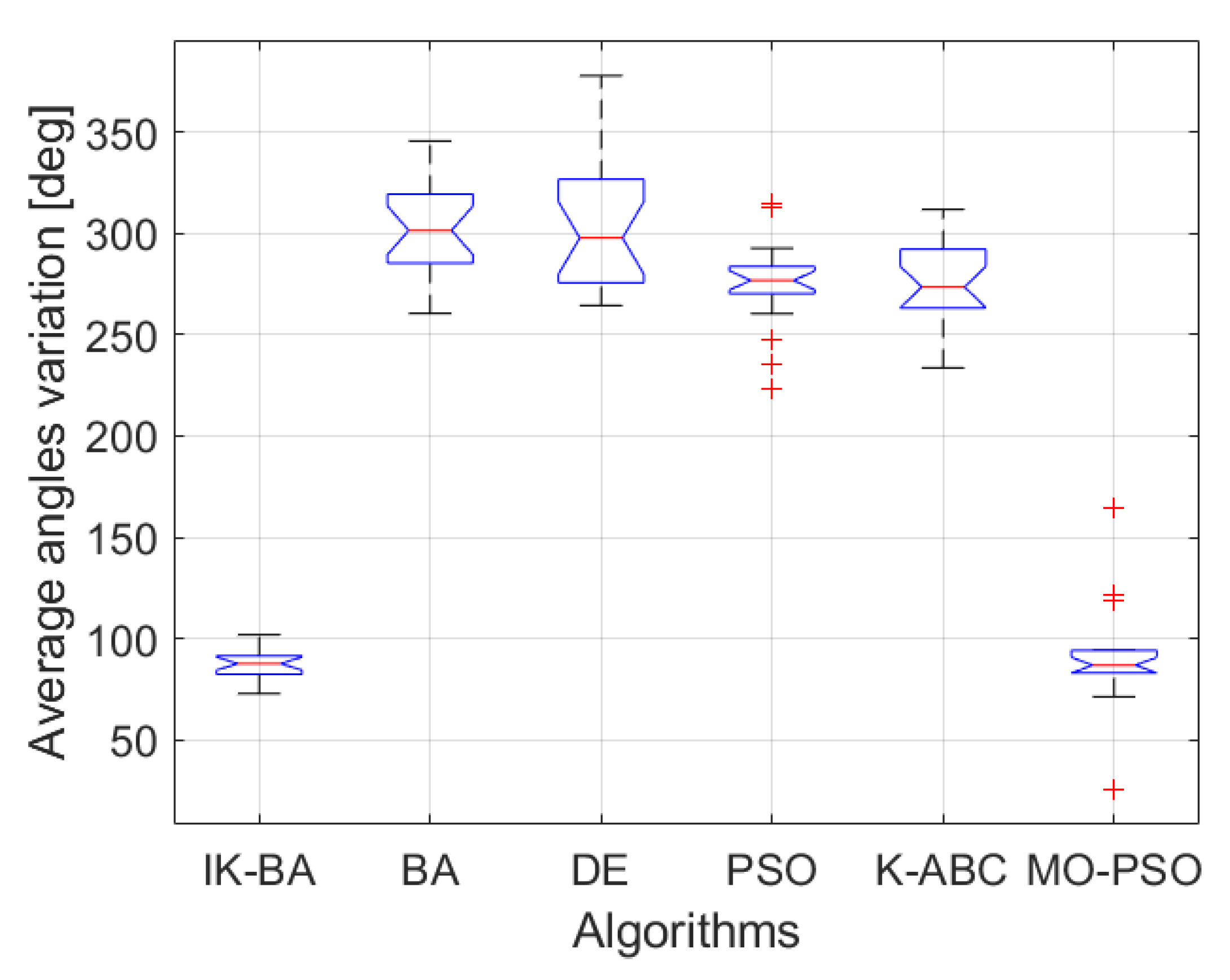
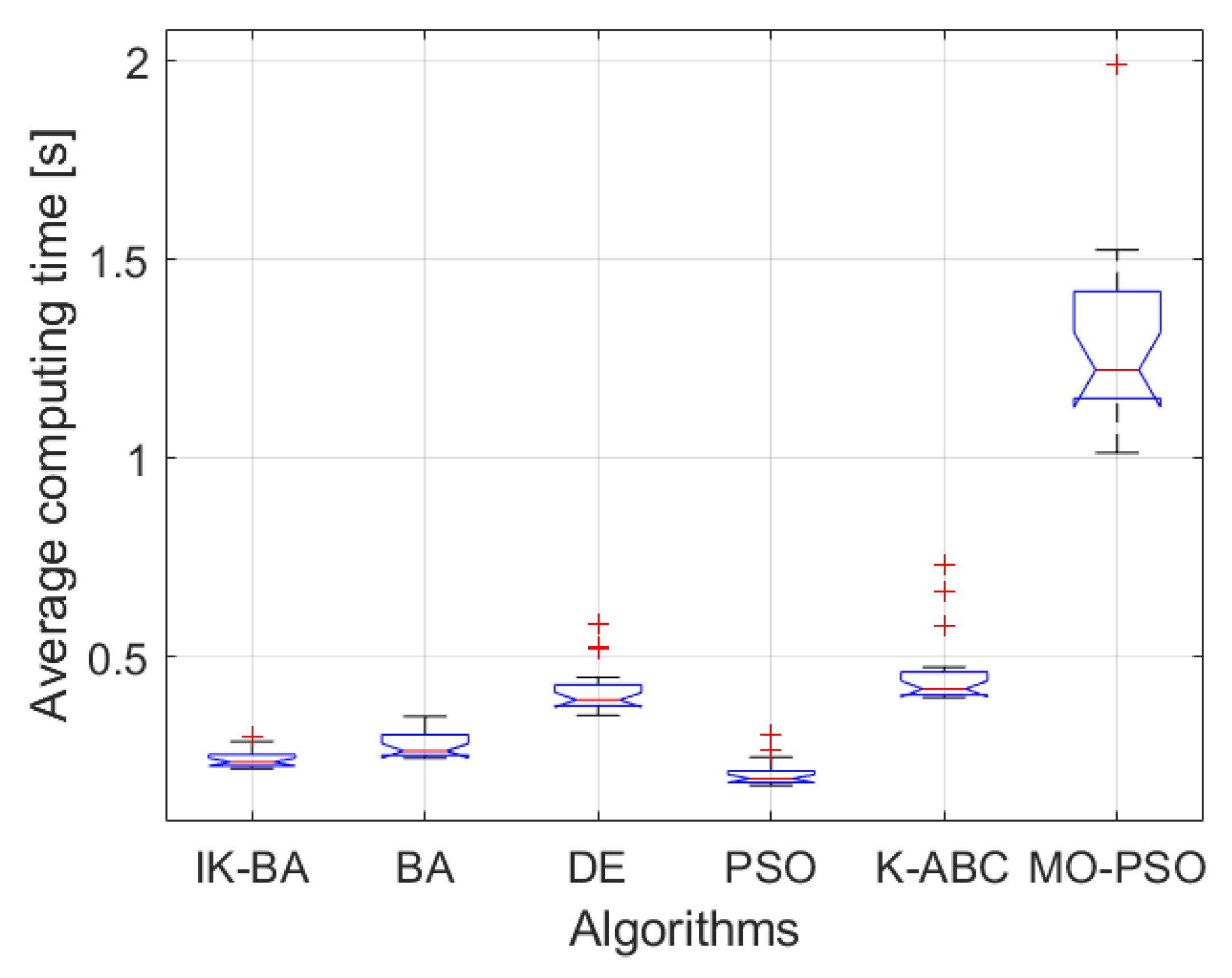
Figure 6 demonstrates that the proposed IK-BA provides finer IK solutions in terms of accuracy and repeatability since it has the least average position error among the compared algorithms. Figure 7 shows that both the IK-BA and MO-PSO algorithms present IK solutions with the least angles variation from point to point of the trajectory. This is affirmed in Figure 9, which shows that IK-BA and MO-PSO generate smooth angles variation along the trajectory, in contrary to the uneven angles variation generated by the other used algorithms. In term of computing time, Figure 8 shows that PSO has the least computational time in 200 iterations, whereas the MO-PSO ranks last in term of computing time.
The performance of the compared algorithms is statistically analysed to give an accurate measurement of the effectiveness of IK-BA compared to other algorithms. Table 3 shows the results of the statistical analyses of the employed algorithms for the path tracking test. A one-way analysis of variance (ANOVA) is also suggested to check if there is a statistical difference between the suggested algorithm and the other algorithms.
Therefore, to inspect the significant difference among the compared algorithms, the parametric statistical test ANOVA is employed, using 0.05 significance level. Table 4, Table 5 and Table 6, show the ANOVA test results for position error, angles variation and computational time, respectively.
The components of ANOVA tables are briefly explained as follows [51]:
  • Source: stands for source of variation, which could be a variation between groups (algorithms’ sample results), or error variation, indicating a variation within the groups.
  • SS: stands for sums of squares.
  • df: degrees of freedom, which indicates the number of independent data.
  • MS: mean squares, they are calculated by dividing sums of squares (SS) by their appropriate degrees of freedom.
  • F: refers to the F-statistic, which used to test the null hypothesis that the means of several groups are equal. It is calculated as the ratio of the variation between the groups to the variation within the groups.
  • Prop > F: indicates the p-value which is used to determine the level of significance of the F-statistic and helps to decide whether the null hypothesis of equal means is rejected or not.
The box plots for ANOVA tests are illustrated in Figure 10, Figure 11 and Figure 12. They represent the results of the performance of each algorithm in terms of position error, angles variation and computing time, respectively.

5.3. Time Assessment

Two-time assessments have been conducted to evaluate the potentials of IK-BA regarding time complexity and its real time potentials.
The first test was conducted using the following hardware configuration: Intel core i5 processor, with 8 Go RAM DDR3.
The time assessment for a possible evaluation of the IK-BA was done using the following configuration: intel i7 processor, with 12 Go RAM (4 Go DDR4 + 8 Go DIMM)

5.3.1. Time Assessment of the IK-BA for Real-Time Path Planning

The time assessment for a possible evaluation of the IK-BA was carried out using the following configuration: Intel i7 processor, with 4 Go RAM DDR4 + 8 Go DIMM memory. The system was running under MS Windows 11 and using MATLAB 2019. The test was performed using N = 12 ,   15   and   20 bats with the same intrinsic parameters of IK-BA presented in Table 1.
All data and variables used were cleared from one test to another. Only the operating system and MATLAB were active during the tests. The termination criterion of the algorithm processing was to a positional error ε p = 0.1   cm . The algorithm had run 20 times, where a random target point was generated at each run. All target points were generated within the workspace of the KUKA LBR iiwa 14 R820 robot.
Statistical results of the time assessment test of the proposed IK-BA are presented in Table 7. They show that IK-BA may be used as a real-time path planner when the number of agents is about 12 or less; meanwhile, for higher configuration results confirmed, it can be used offline only, meaning it can be used to plan the path before coding the robot.

5.3.2. Discussion on Time Processing of MH Inverse Solvers

The industrial processing consists in reproducing the path for a needed task, as part of a production plan. In general, the path planning is offline-generated, verified and tested through simulations, then applied, for a real validation on the target robot.
In Table 3, the computing time comparatives correspond to the processing time, where the termination criterion is defined by a maximum number of iteration t m a x = 200 iterations. The next section presents a time assessment of the IK-BA, where the termination criterion is set according to a maximum acceptable IK positional error.
The configuration used in test detailed by Table 3 is based on 20 agents for all algorithms. The termination criterion is used to ensure that the algorithm does not run indefinitely. The termination criterion can greatly affect the performance of the algorithm. Commonly, the termination criterion is defined by a maximum number of iterations, or according to an acceptable quality of the provided solution. The algorithm is stopped when the quality of the best solution found, while processing reaches a certain threshold [52].
Assuming this and in regards of the results in Table 7, it is evident that the proposed algorithm is suitable for offline path planning. It shows better time processing than its challengers, while not meeting a real-time path planning constraint (less than 50 ms). The potentials of the IK-BA as a real-time path planner are discussed in the next paragraph.
A real-time system is one that is capable to procure a deterministic response in a specified time frame. If this time frame is critical and must be strictly respected, the system is assumed to be a hard real-time system. In contrast, when the time may be subject to delay, the system is assumed to be a soft real-time system [53,54].
According to our previous experimentation, we proved that the proposal may respect a real-time constraint for each given configuration; the most effective number of bats is the one with 12 agents, where the response time is less than 50 ms.

6. Real Application

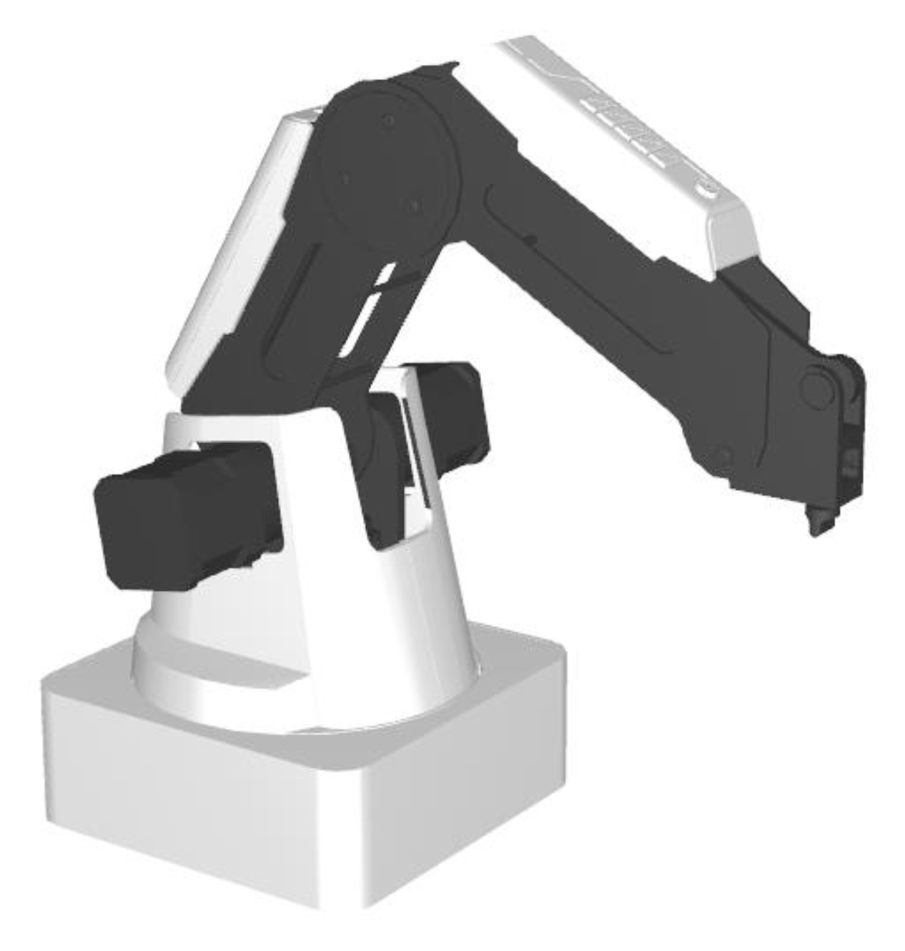
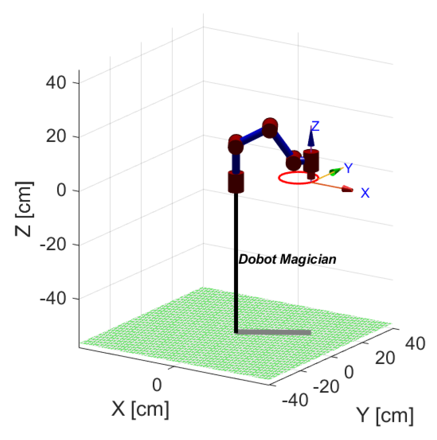
The proposed IK-BA is employed as an IK solver for the Dobot magician robotic arm. The Dobot magician robot presented in Figure 13 is a desktop 4-Dof robot that could be used for different tasks such as laser engraving, 3D printing, drawing and calligraphy.
In this application, the robot’s end-effector is intended to follow a circular trajectory discredited by 20 points distributed along the trajectory as shown in Figure 14. The circular path is defined by a center C = [ 16   cm ,   16   cm ,   0 ] . and a radius r = 7   cm , which is generated along the workspace of the Dobot magician robotic arm as revealed in Figure 15.
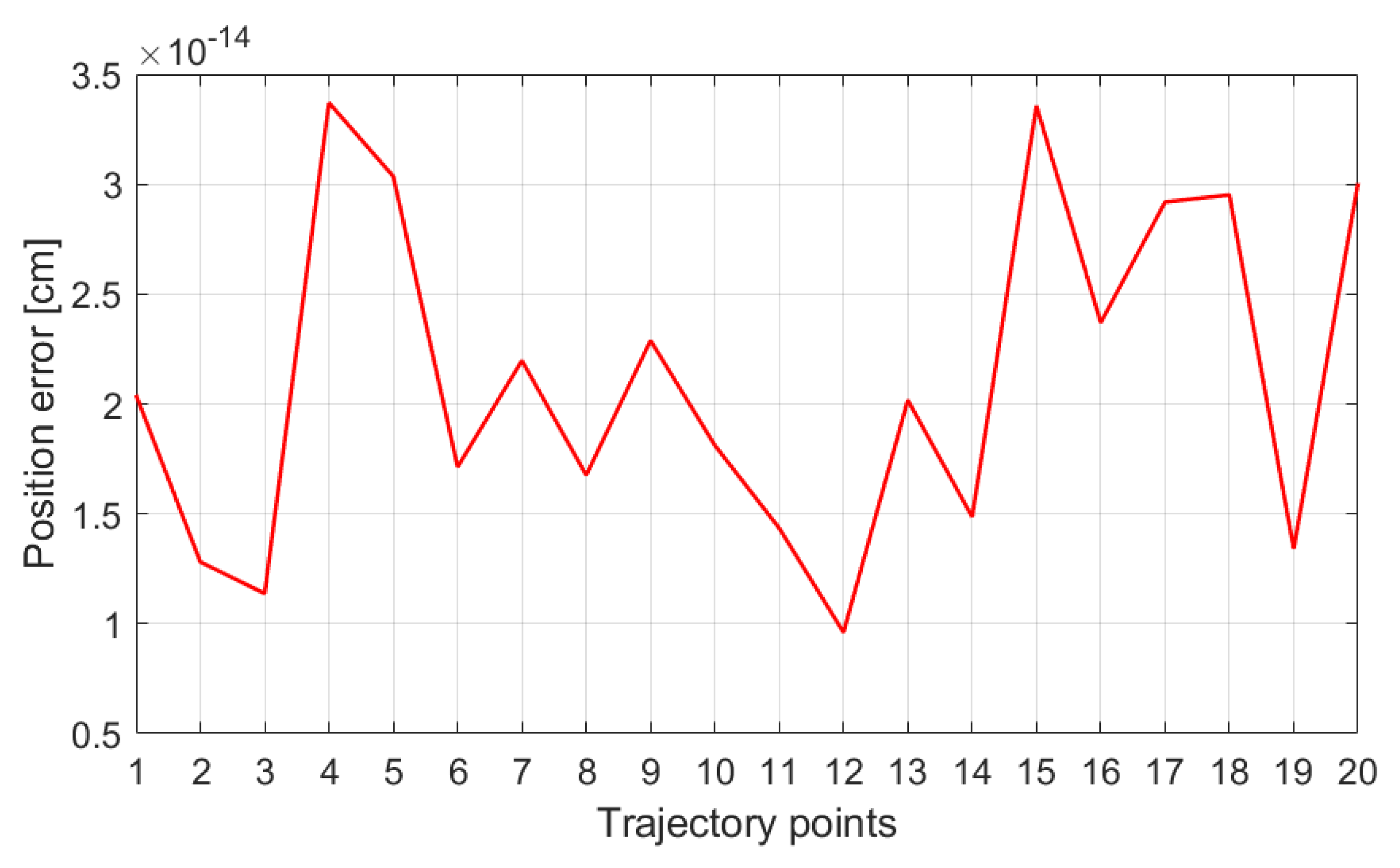
The points reached by the robot’s end-effector along with the actual trajectory points are presented in Figure 15. Figure 16 shows the corresponding generated joint angles for each point of the trajectory using IK-BA. θ 4 is set to be equal to θ 1 , to obtain a fixed orientation of the end-effector. The positional error of the robot’s end-effector is relative to the trajectory points represented in Figure 17.
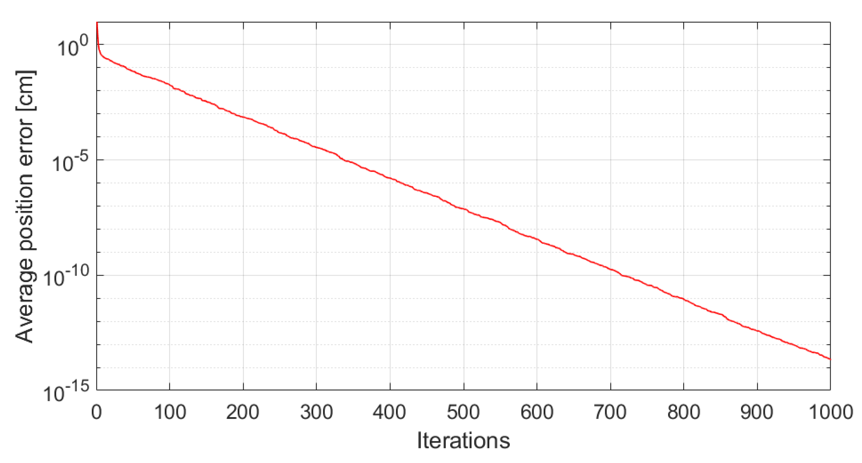
The proposed IK-BA provided accurate solutions of an error in a range of 10−14 cm. Figure 18 shows that the average error among the 20 points of the trajectory reaches 2.1196 × 10⁻¹⁴ cm along 1000 iterations. Table 8 represents the twenty joint positions used for the test, the position error of the solver in respect to pen orientation. All returned solutions obtained a precision higher than the system needs and the measured observed positions can not exceed the mechanical frame constraints of the real robot as testified by its provider.
It is important to note that the proposed solver is retuning solutions which are much higher in precision than the system can mechanically perform, since the mechanical system precision is limited to 0.02 cm [55]. A solver should always produce solutions as precisely as possible, but usually where the precision is higher than what the mechanical system can perform.

7. Conclusions

A specially improved BA algorithm variant dedicated for the IK robotic problem is suggested in this paper. The proposed method is called IK-BA; it stands for a specific bat algorithm dedicated to robotic-arms’ inverse geometric solution, where the elongation control mechanism is embedded in its update equations. The proposed IK-BA is qualified of giving accurate solutions while guaranteeing minimal joints variation from the initial position towards the target point. The importance of this feature stands out in path tracking tasks, which enables generation of smooth angle variation from point-to-point of the trajectory. This improvement is established through adjusting the update equation in such a way that it takes into account the initial angular position of the robot. When the orientation of the end-effector is required in addition to a desired end-effector position, a manipulator decoupling method is suggested, where the three last joints of the manipulator are calculated deterministically; whereas, the remaining first joints are determined using the proposed IK-BA. This methodology is tested using the simulation of path tracking task of the KUKA LBR iiwa 14 R820, in which it is required to follow a helical trajectory. The effectiveness of the proposed approach is proved by a comparative study with the standard BA algorithm and other optimization algorithms from the literature, including DE, PSO, K-ABC and MO-PSO. The statistical analyses supported by a one-way ANOVA test show that the IK-BA has the best compromise between the accuracy of the solution, the angles variation and the computing time.

Author Contributions

Conceptualization, N.R. and M.S. methodology, N.R. and M.S.; software, N.R. and M.S.; validation, all authors; formal analysis, all authors; investigation, N.R. and M.S.; resources, all authors; data curation, all authors; writing—original draft preparation, all authors; writing—review and editing, all authors; visualization, all authors; supervision, N.R. and M.A.T.; project administration, all authors; funding acquisition, all authors. All authors have read and agreed to the published version of the manuscript.

Funding

This research received no external funding.

Data Availability Statement

Not applicable.

Conflicts of Interest

The authors declare no conflict of interest.

References

  1. Yim, M.; Shen, W.; Salemi, B.; Rus, D.; Moll, M.; Lipson, H.; Klavins, E.; Chirikjian, G.S. Modular Self-Reconfigurable Robot Systems [Grand Challenges of Robotics]. IEEE Robot. Autom. Mag. 2007, 14, 43–52. [Google Scholar] [CrossRef]
  2. Wallén, J. The History of the Industrial Robot; Linköping University Electronic Press: Linköping, Sweden, 2008. [Google Scholar]
  3. Olofsson, B.; Nielsen, L. Path-Tracking Velocity Control for Robot Manipulators with Actuator Constraints. Mechatronics 2017, 45, 82–99. [Google Scholar] [CrossRef]
  4. Antonelli, G.; Chiaverini, S.; Fusco, G. An Algorithm for Online Inverse Kinematics with Path Tracking Capability under Velocity and Acceleration Constraints. In Proceedings of the 39th IEEE Conference on Decision and Control (Cat. No.00CH37187), Sydney, NSW, Australia, 12–15 December 2000; Volume 5, pp. 5079–5084. [Google Scholar]
  5. Denavit, J.; Hartenberg, R.S. A Kinematic Notation for Lower-Pair Mechanisms Based on Matrices. J. Appl. Mech. 1955, 22, 215–221. [Google Scholar] [CrossRef]
  6. Kucuk, S.; Bingul, Z. Robot Kinematics: Forward and Inverse Kinematics; IntechOpen: Rijeka, Croatia, 2006; ISBN 9783866112858. [Google Scholar]
  7. Bingul, Z.; Ertunc, H.M.; Oysu, C. Applying Neural Network to Inverse Kinematic Problem for 6R Robot Manipulator with Offset Wrist. In Proceedings of the Adaptive and Natural Computing Algorithms, Coimbra, Portugal, 21–23 March 2005; Ribeiro, B., Albrecht, R.F., Dobnikar, A., Pearson, D.W., Steele, N.C., Eds.; Springer: Vienna, Austria, 2005; pp. 112–115. [Google Scholar]
  8. Secară, C.; Vlădăreanu, L. Iterative Genetic Algorithm Based Strategy for Obstacles Avoidance of a Redundant Manipulator. In Proceedings of the 2010 American Conference on Applied Mathematics, Cambridge, MA, USA, 27–29 January 2010; World Scientific and Engineering Academy and Society (WSEAS): Stevens Point, WI, USA, 2010; pp. 361–366. [Google Scholar]
  9. Oulhadj, H.; Daachi, B.; Menasri, R. Metaheuristics for Robotics; John Wiley & Sons: Hoboken, NJ, USA, 2020; ISBN 9781786303806. [Google Scholar]
  10. El-Sherbiny, A.; Elhosseini, M.A.; Haikal, A.Y. A Comparative Study of Soft Computing Methods to Solve Inverse Kinematics Problem. Ain Shams Eng. J. 2018, 9, 2535–2548. [Google Scholar] [CrossRef]
  11. Waldron, K.J.; Schmiedeler, J. Kinematics. In Springer Handbook of Robotics; Siciliano, B., Khatib, O., Eds.; Springer Handbooks; Springer International Publishing: Cham, Switzerland, 2016; pp. 11–36. ISBN 9783319325521. [Google Scholar]
  12. Köker, R.; Öz, C.; Çakar, T.; Ekiz, H. A Study of Neural Network Based Inverse Kinematics Solution for a Three-Joint Robot. Robot. Auton. Syst. 2004, 49, 227–234. [Google Scholar] [CrossRef]
  13. Guo, J.; Cherkassky, V. Cherkassky A Solution to the Inverse Kinematic Problem in Robotics Using Neural Network Processing. In Proceedings of the International 1989 Joint Conference on Neural Networks, Washington, DC, USA, 18–22 June 1989; Volume 2, pp. 299–304. [Google Scholar]
  14. Cursi, F.; Bai, W.; Yeatman, E.M.; Kormushev, P. Task Accuracy Enhancement for a Surgical Macro-Micro Manipulator with Probabilistic Neural Networks and Uncertainty Minimization. IEEE Trans. Autom. Sci. Eng. 2022, 1–16. [Google Scholar] [CrossRef]
  15. Wichapong, K.; Bureerat, S.; Pholdee, N. Solving Inverse Kinematics of Robot Manipulators by Means of Meta-Heuristic Optimisation. IOP Conf. Ser. Mater. Sci. Eng. 2018, 370, 012056. [Google Scholar] [CrossRef]
  16. Abdel-Basset, M.; Abdel-Fatah, L.; Sangaiah, A.K. Chapter 10—Metaheuristic Algorithms: A Comprehensive Review. In Computational Intelligence for Multimedia Big Data on the Cloud with Engineering Applications; Sangaiah, A.K., Sheng, M., Zhang, Z., Eds.; Intelligent Data-Centric Systems; Academic Press: Cambridge, MA, USA, 2018; pp. 185–231. ISBN 9780128133149. [Google Scholar]
  17. Tian, Z.; Fong, S. Survey of Meta-Heuristic Algorithms for Deep Learning Training; IntechOpen: Rijeka, Croatia, 2016; ISBN 9789535125938. [Google Scholar]
  18. Ahuactzin, J.M.; Gupta, K.K. The Kinematic Roadmap: A Motion Planning Based Global Approach for Inverse Kinematics of Redundant Robots. IEEE Trans. Robot. Autom. 1999, 15, 653–669. [Google Scholar] [CrossRef]
  19. Jones, D.R.; Schonlau, M.; Welch, W.J. Efficient Global Optimization of Expensive Black-Box Functions. J. Glob. Optim. 1998, 13, 455–492. [Google Scholar] [CrossRef]
  20. Cursi, F.; Bai, W.; Yeatman, E.M.; Kormushev, P. GlobDesOpt: A Global Optimization Framework for Optimal Robot Manipulator Design. IEEE Access 2022, 10, 5012–5023. [Google Scholar] [CrossRef]
  21. Craig, J.J. Introduction to Robotics: Mechanics and Control; Pearson Educación: London, UK, 2005; ISBN 9789702607724. [Google Scholar]
  22. Spong, M.W.; Hutchinson, S.; Vidyasagar, M. Robot Modeling and Control, 1st ed.; Wiley: Hoboken, NJ, USA, 2005; ISBN 9780471649908. [Google Scholar]
  23. Abdor-Sierra, J.A.; Merchán-Cruz, E.A.; Rodríguez-Cañizo, R.G. A Comparative Analysis of Metaheuristic Algorithms for Solving the Inverse Kinematics of Robot Manipulators. Results Eng. 2022, 16, 100597. [Google Scholar] [CrossRef]
  24. Holland, J.H. Adaptation in Natural and Artificial Systems: An Introductory Analysis with Applications to Biology, Control and Artificial Intelligence; MIT Press: Cambridge, MA, USA, 1992; ISBN 9780262581110. [Google Scholar]
  25. Goldberg, D.E.; Holland, J.H. Genetic Algorithms and Machine Learning. Mach. Learn. 1988, 3, 95–99. [Google Scholar] [CrossRef]
  26. Parker, J.K.; Khoogar, A.R.; Goldberg, D.E. Inverse Kinematics of Redundant Robots Using Genetic Algorithms. In 1989 IEEE International Conference on Robotics and Automation; IEEE Computer Society: Washington, DC, USA, 1989; pp. 271–276. [Google Scholar]
  27. Nearchou, A.C. Solving the Inverse Kinematics Problem of Redundant Robots Operating in Complex Environments via a Modified Genetic Algorithm. Mech. Mach. Theory 1998, 33, 273–292. [Google Scholar] [CrossRef]
  28. Tarokh, M.; Zhang, X. An Adaptive Genetic Algorithm for Real-Time Robotic Trajectory Tracking. IFAC Proc. Vol. 2006, 39, 199–204. [Google Scholar] [CrossRef]
  29. Yang, X.-S. Chapter 14—Multi-Objective Optimization. In Nature-Inspired Optimization Algorithms; Yang, X.-S., Ed.; Elsevier: Oxford, UK, 2014; pp. 197–211. ISBN 9780124167438. [Google Scholar]
  30. Kennedy, J.; Eberhart, R. Particle Swarm Optimization. In Proceedings of the ICNN’95—International Conference on Neural Networks, Perth, WA, Australia, 27 November–1 December 1995; Volume 4, pp. 1942–1948. [Google Scholar]
  31. Rokbani, N.; Alimi, A.M. Inverse Kinematics Using Particle Swarm Optimization: A Statistical Analysis. Procedia Eng. 2013, 64, 1602–1611. [Google Scholar] [CrossRef] [Green Version]
  32. Huang, H.-C.; Chen, C.-P.; Wang, P.-R. Particle Swarm Optimization for Solving the Inverse Kinematics of 7-DOF Robotic Manipulators. In Proceedings of the 2012 IEEE International Conference on Systems, Man, and Cybernetics (SMC), Seoul, Republic of Korea, 14–17 October 2012; pp. 3105–3110. [Google Scholar]
  33. Rokbani, N.; Slim, M.; Alimi, A.M. The Beta Distributed PSO, β-PSO, with Application to Inverse Kinematics. In Proceedings of the 2021 National Computing Colleges Conference (NCCC), Taif, Saudi Arabia, 27–28 March 2021; pp. 1–6. [Google Scholar]
  34. Adly, M.A.; Abd-El-Hafiz, S. Inverse Kinematics Using Single- and Multi-Objective Particle Swarm Optimization. In Proceedings of the 2016 28th International Conference on Microelectronics (ICM), Giza, Italy, 17–20 December 2016. [Google Scholar] [CrossRef]
  35. Tripathi, P.K.; Bandyopadhyay, S.; Pal, S.K. Multi-Objective Particle Swarm Optimization with Time Variant Inertia and Acceleration Coefficients. Inf. Sci. 2007, 177, 5033–5049. [Google Scholar] [CrossRef] [Green Version]
  36. Rokbani, N.; Neji, B.; Slim, M.; Mirjalili, S.; Ghandour, R. A Multi-Objective Modified PSO for Inverse Kinematics of a 5-DOF Robotic Arm. Appl. Sci. 2022, 12, 7091. [Google Scholar] [CrossRef]
  37. Bayati, M. Using Cuckoo Optimization Algorithm and Imperialist Competitive Algorithm to Solve Inverse Kinematics Problem for Numerical Control of Robotic Manipulators. Proc. Inst. Mech. Eng. Part I J. Syst. Control. Eng. 2015, 229, 375–387. [Google Scholar] [CrossRef]
  38. El-Sherbiny, A.; Elhosseini, M.A.; Haikal, A.Y. A New ABC Variant for Solving Inverse Kinematics Problem in 5 DOF Robot Arm. Appl. Soft Comput. 2018, 73, 24–38. [Google Scholar] [CrossRef]
  39. Zhang, L.; Xiao, N. A Novel Artificial Bee Colony Algorithm for Inverse Kinematics Calculation of 7-DOF Serial Manipulators. Soft Comput. 2019, 23, 3269–3277. [Google Scholar] [CrossRef]
  40. Rokbani, N.; Casals, A.; Alimi, A.M. IK-FA, a New Heuristic Inverse Kinematics Solver Using Firefly Algorithm. In Computational Intelligence Applications in Modeling and Control; Azar, A.T., Vaidyanathan, S., Eds.; Studies in Computational Intelligence; Springer International Publishing: Cham, Switzerland, 2015; pp. 369–395. ISBN 9783319110172. [Google Scholar]
  41. Dereli, S.; Köker, R. Calculation of the Inverse Kinematics Solution of the 7-DOF Redundant Robot Manipulator by the Firefly Algorithm and Statistical Analysis of the Results in Terms of Speed and Accuracy. Inverse Probl. Sci. Eng. 2020, 28, 601–613. [Google Scholar] [CrossRef]
  42. Rokbani, N.; Mirjalili, S.; Slim, M.; Alimi, A.M. A Beta Salp Swarm Algorithm Meta-Heuristic for Inverse Kinematics and Optimization. Appl. Intell. 2022, 52, 10493–10518. [Google Scholar] [CrossRef]
  43. Lopez-Franco, C.; Diaz, D.; Hernandez-Barragan, J.; Arana-Daniel, N.; Lopez-Franco, M. A Metaheuristic Optimization Approach for Trajectory Tracking of Robot Manipulators. Mathematics 2022, 10, 1051. [Google Scholar] [CrossRef]
  44. Kanagaraj, G.; Masthan, S.S.; Yu, V.F. Meta-Heuristics Based Inverse Kinematics of Robot Manipulator’s Path Tracking Capability Under Joint Limits. Mendel 2022, 28, 41–54. [Google Scholar] [CrossRef]
  45. Lopez-Franco, C.; Hernandez-Barragan, J.; Alanis, A.Y.; Arana-Daniel, N. A Soft Computing Approach for Inverse Kinematics of Robot Manipulators. Eng. Appl. Artif. Intell. 2018, 74, 104–120. [Google Scholar] [CrossRef]
  46. Yang, X.-S. A New Metaheuristic Bat-Inspired Algorithm. In Nature Inspired Cooperative Strategies for Optimization (NICSO 2010); González, J.R., Pelta, D.A., Cruz, C., Terrazas, G., Krasnogor, N., Eds.; Studies in Computational Intelligence; Springer: Berlin/Heidelberg, Germany, 2010; pp. 65–74. ISBN 9783642125386. [Google Scholar]
  47. Yang, X.-S. Chapter 10—Bat Algorithms. In Nature-Inspired Optimization Algorithms; Yang, X.-S., Ed.; Elsevier: Oxford, UK, 2014; pp. 141–154. ISBN 9780124167438. [Google Scholar]
  48. Gupta, A. BAT Optimization Algorithm. Available online: https://www.mathworks.com/matlabcentral/fileexchange/68981-bat-optimization-algorithm (accessed on 31 August 2022).
  49. Martínez-Cagigal, V. Multi-Objective Particle Swarm Optimization (MOPSO)—File Exchange—MATLAB Central. Available online: https://www.mathworks.com/matlabcentral/fileexchange/62074-multi-objective-particle-swarm-optimization-mopso (accessed on 17 September 2022).
  50. Chiaverini, S.; Oriolo, G.; Walker, I.D. Kinematically Redundant Manipulators. In Springer Handbook of Robotics; Siciliano, B., Khatib, O., Eds.; Springer: Berlin/Heidelberg, Germany, 2008; pp. 245–268. ISBN 9783540303015. [Google Scholar]
  51. Sawilowsky, S.S. Nonparametric Tests of Interaction in Experimental Design. Rev. Educ. Res. 1990, 60, 91–126. [Google Scholar] [CrossRef]
  52. Arora, J.S. Chapter 17—Nature-Inspired Search Methods. In Introduction to Optimum Design, 4th ed.; Arora, J.S., Ed.; Academic Press: Boston, MA, USA, 2017; pp. 739–769. ISBN 9780128008065. [Google Scholar]
  53. Liu, J.W.S. Real-Time Systems, 1st ed.; Prentice Hall: Upper Saddle River, NJ, USA, 2000; ISBN 9780130996510. [Google Scholar]
  54. Laplante, P.A. Real-Time Systems Design and Analysis: Laplante/Real-Time Systems Design; John Wiley & Sons, Inc.: Hoboken, NJ, USA, 2004; ISBN 9780471648291. [Google Scholar]
  55. Nguyen, H. Design of Laser Engraving Environment for Dobot Magician. Bachelor’s Thesis, Häme University of Applied Sciences, Hämeenlinna, Finland, 2022. [Google Scholar]
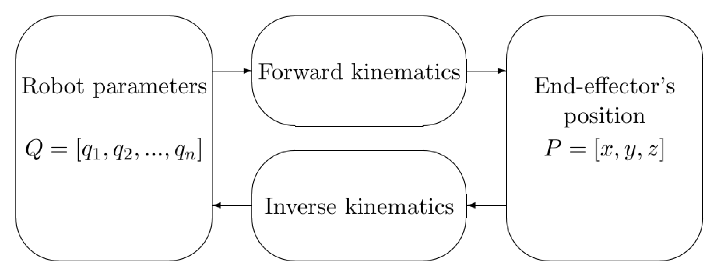
Figure 1. Relation between forward and inverse kinematics.
Robotics 12 00038 g001
Figure 2. Wrist’s position relative to the end-effector’s position.
Robotics 12 00038 g002
Figure 3. Flowchart of the proposed methodology.
Robotics 12 00038 g003
Figure 4. Kinematic scheme of KUKA LBR iiwa 14 R820.
Robotics 12 00038 g004
Figure 5. Helical trajectory for the path tracking test.
Robotics 12 00038 g005
Figure 6. Average position error in path tracking.
Robotics 12 00038 g006
Figure 7. Average angles variation from point-to-point in path tracking.
Robotics 12 00038 g007
Figure 8. Average computing time for IK solutions from point-to-point in path tracking.
Robotics 12 00038 g008
Figure 9. Generated joint angles along the trajectory using (a) IK-BA (b) BA (c) DE (d) PSO (e) K-ABC (f) MO-PSO.
Robotics 12 00038 g009aRobotics 12 00038 g009bRobotics 12 00038 g009c
Figure 10. Box plot of the ANOVA test of average position error.
Robotics 12 00038 g010
Figure 11. Box plot of the ANOVA test of average angles variation.
Robotics 12 00038 g011
Figure 12. Box plot of the ANOVA test of average computational time.
Robotics 12 00038 g012
Figure 13. Dobot magician robot.
Robotics 12 00038 g013
Figure 14. Actual trajectory and end-effector’s trajectory.
Robotics 12 00038 g014
Figure 15. Dobot magician robot and circular trajectory.
Robotics 12 00038 g015
Figure 16. Generated joint angles using IK-BA along the trajectory.
Robotics 12 00038 g016
Figure 17. Position error between the robot’s end-effector and the target point of the trajectory.
Robotics 12 00038 g017
Figure 18. Average position error curve along 1000 iterations.
Robotics 12 00038 g018
Table 1. Intrinsic parameters values for the IK-BA and the ordinary BA.
AlgorithmParametersValues
IK-BAFrequency range [ f m i n ,   f m a x ] [0, 2]
Increasing coefficient ( α ) 0.97
Attenuation coefficient ( γ )0.1
Loudness for each bat ( A i t )1
Initial pulse rate ( r i t )1
BA
[48]
Frequency range [ f m i n ,   f m a x ] [0, 2]
Increasing coefficient ( α ) 0.5
Attenuation coefficient ( γ )0.5
Loudness for each bat ( A i t )Random number in the range of [0, 1]
Initial pulse rate ( r i t )0.001
DE
[45]
Scaling factor ( F )0.6
Cross-over factor ( C )0.9
PSO
[43]
Inertia weight ( w )1.1312
Individual confidence factor ( c 1 )2.0149
Swarm confidence factor ( c 2 )0.53514
K-ABC
[38]
No intrinsic parameters
MO-PSO
[49]
Inertia weight ( w )0.5
Individual confidence factor ( c 1 )2
Swarm confidence factor ( c 2 )2
Number of grids in each dimension ( N g r i d )20
Maximum velocity ( V m a x )5
Uniform mutation percentage ( u m u t )0.5
Table 2. DH parameters of KUKA LBR iiwa 18 R820 robot manipulator.
Link i θ i d i a i α i [deg]Range [deg]
1 θ 1 d 1 0−90[−170, 170]
2 θ 2 0090[−120, 120]
3 θ 3 d 3 090[−170, 170]
4 θ 4 00−90[−120, 120]
5 θ 5 d 5 0−90[−170, 170]
6 θ 6 0090[−120, 120]
7 θ 7 d 7 00[−175, 175]
Table 3. Statistical analyses of the performance of the employed algorithms.
AlgorithmPerformanceMeanMedianStdMaximumMinimum
IK-BAPosition error [cm]0.00190.00191.7824 × 10−40.00220.0016
Angles variation [deg]87.191687.57797.8247101.874072.8021
Computing time [s]0.24390.23590.02290.30220.2195
BAPosition error [cm]1.68491.53740.90693.94870.1830
Angles variation [deg]301.5794301.553025.2466345.7477260.4859
Computing time [s]0.28000.26420.03350.35110.2462
DEPosition error [cm]0.36530.27930.29290.99810.0387
Angles variation [deg]303.6915297.838332.8049377.9527264.5489
Computing time [s]0.41540.39240.06170.58500.3534
PSOPosition error [cm]0.43820.40190.33121.03840.0000
Angles variation [deg]274.7692276.861821.9459314.8747223.3415
Computing time [s]0.20690.19460.03360.30290.1769
K-ABCPosition error [cm]0.23180.22320.07220.35150.1270
Angles variation [deg]276.6456273.564520.9967311.8878233.6387
Computing time [s]0.45910.42000.09260.73180.3980
MO-PSOPosition error [cm]0.40750.39600.08910.70140.2871
Angles variation [deg]89.960286.803625.6630164.179425.7217
Computing time [s]1.28531.22220.22821.98881.0135
Table 4. ANOVA test results for position error comparatives.
SourceSSdfMSFProb > F
Algorithms35.033857.006840.76857.2225 × 10−24
Error19.59291140.1719
Total54.6267119
Table 5. ANOVA test for angles variation comparatives.
SourceSSdfMSFProb > F
Algorithms1.0877 × 10652.1754 × 105388.93967.1885 × 10−70
Error6.3761 × 104114559.3091
Total1.1514 × 106119
Table 6. ANOVA test for computing time comparatives.
SourceSSdfMSFProb > F
Algorithms16.470053.2940293.97662.1670 × 10−63
Error1.27741140.0112
Total17.7474119
Table 7. Statistical results of time assessment test (time is in ms).
Number of BatsMean Time in msMedianStdMaximumMinimum
1248.0145.810.167.232.6
1561.0964.1012.8592.3541.81
2083.7573.0328.9680.0647.88
30180,94101.29149.67448.4469.52
Table 8. Generated joint angles and their corresponding error using IK-BA for the 20 points of the trajectory.
Trajectory PointsJoint Angles [deg]Position Error [cm]
θ 1 θ 2 θ 3 θ 4
134.866.549.534.82.04 × 10−14
238.769.645.638.71.28 × 10−14
342.971.443.542.91.14 × 10−14
447.171.443.547.13.37 × 10−14
551.369.645.651.33.04 × 10−14
655.266.549.555.21.71 × 10−14
758.662.654.858.62.20 × 10−14
861.258.461.161.21.68 × 10−14
962.854.668.062.82.29 × 10−14
1062.851.575.262.81.81 × 10−14
1160.649.582.260.61.43 × 10−14
1256.048.888.356.09.61 × 10−14
1349.048.892.049.02.02 × 10−14
1441.048.892.041.01.49 × 10−14
1534.048.888.334.03.36 × 10−14
1629.449.582.229.42.37 × 10−14
1727.251.575.227.22.92 × 10−14
1827.254.668.027.22.95 × 10−14
1928.858.461.128.81.34 × 10−14
2031.462.654.831.43.00 × 10−14
Disclaimer/Publisher’s Note: The statements, opinions and data contained in all publications are solely those of the individual author(s) and contributor(s) and not of MDPI and/or the editor(s). MDPI and/or the editor(s) disclaim responsibility for any injury to people or property resulting from any ideas, methods, instructions or products referred to in the content.