Article

A Novel Adaptive Sliding Mode Controller for a 2-DOF Elastic Robotic Arm †

1
Department of Engineering Sciences, University of Agder (UiA), Jon Lilletuns vei 9, 4879 Grimstad, Norway
2
Department of Electrical and Electronic Engineering, Ho Chi Minh City University of Technology (HCMUT), Ho Chi Minh City 700000, Vietnam
*
Author to whom correspondence should be addressed.
This paper is an extended version of our paper published in Tuan, H.M.; Sanfilippo, F.; Hao, N.V. An Adaptive Sliding Mode Controller for a 2-DOF Elastic Robotic Arm. Proc. of the 4th International Conference on Intelligent Technologies and Applications (INTAP 2021), Grimstad, Norway, 2021. accepted for publication.
Robotics 2022, 11(2), 47; https://doi.org/10.3390/robotics11020047
Submission received: 24 February 2022 / Revised: 24 March 2022 / Accepted: 29 March 2022 / Published: 5 April 2022
(This article belongs to the Special Issue Intelligent Technologies and Robotics)

Abstract

:
Collaborative robots (or cobots) are robots that are capable of safely operating in a shared environment or interacting with humans. In recent years, cobots have become increasingly common. Compliant actuators are critical in the design of cobots. In real applications, this type of actuation system may be able to reduce the amount of damage caused by an unanticipated collision. As a result, elastic joints are expected to outperform stiff joints in complex situations. In this work, the control of a 2-DOF robot arm with elastic actuators is addressed by proposing a two-loop adaptive controller. For the outer control loop, an adaptive sliding mode controller (ASMC) is adopted to deal with uncertainties and disturbance on the load side of the robot arm. For the inner loops, model reference adaptive controllers (MRAC) are utilised to handle the uncertainties on the motor side of the robot arm. To show the effectiveness of the proposed controller, extensive simulation experiments and a comparison with the conventional sliding mode controller (SMC) are carried out. As a result, the ASMC has a 50.35% lower average RMS error than the SMC controller, and a shorter settling time (5% criterion) (0.44 s compared to 2.11 s).

1. Introduction

Cobots are primarily passive robots that are meant to work alongside humans in close proximity. In our daily life, cobots assist humans in numerous situations, such as in search and rescue (SAR) missions [1], surveillance and inspection [2], medical support [3], etc. One aspect that sets cobots apart from traditional robots is their capacity to reduce the amount of damage caused by unexpected collisions in a dynamic collaborative working environment. This ability can be achieved in a variety of ways, including the use of force/torque sensors [4], elastic actuators, or a collision detection algorithm, without modifying the physical configuration of the robot [5]. As it is efficient and low-cost, adopting elastic actuators is one of the most common approaches. Elastic actuators provide several advantages compared to rigid actuators, including the ability to filter shock loads and facilitate force regulation. The major goal of using elastic actuators to control robots is to increase the performance of tracking tasks for the joints. Elastic actuators, on the other hand, have a lower force control bandwidth; hence, their position control is slower than stiff actuators. Furthermore, with elastic actuators, uncertainties and disturbances in the system might create oscillation and instability.
To address these challenges, the following contributions are presented in this study:
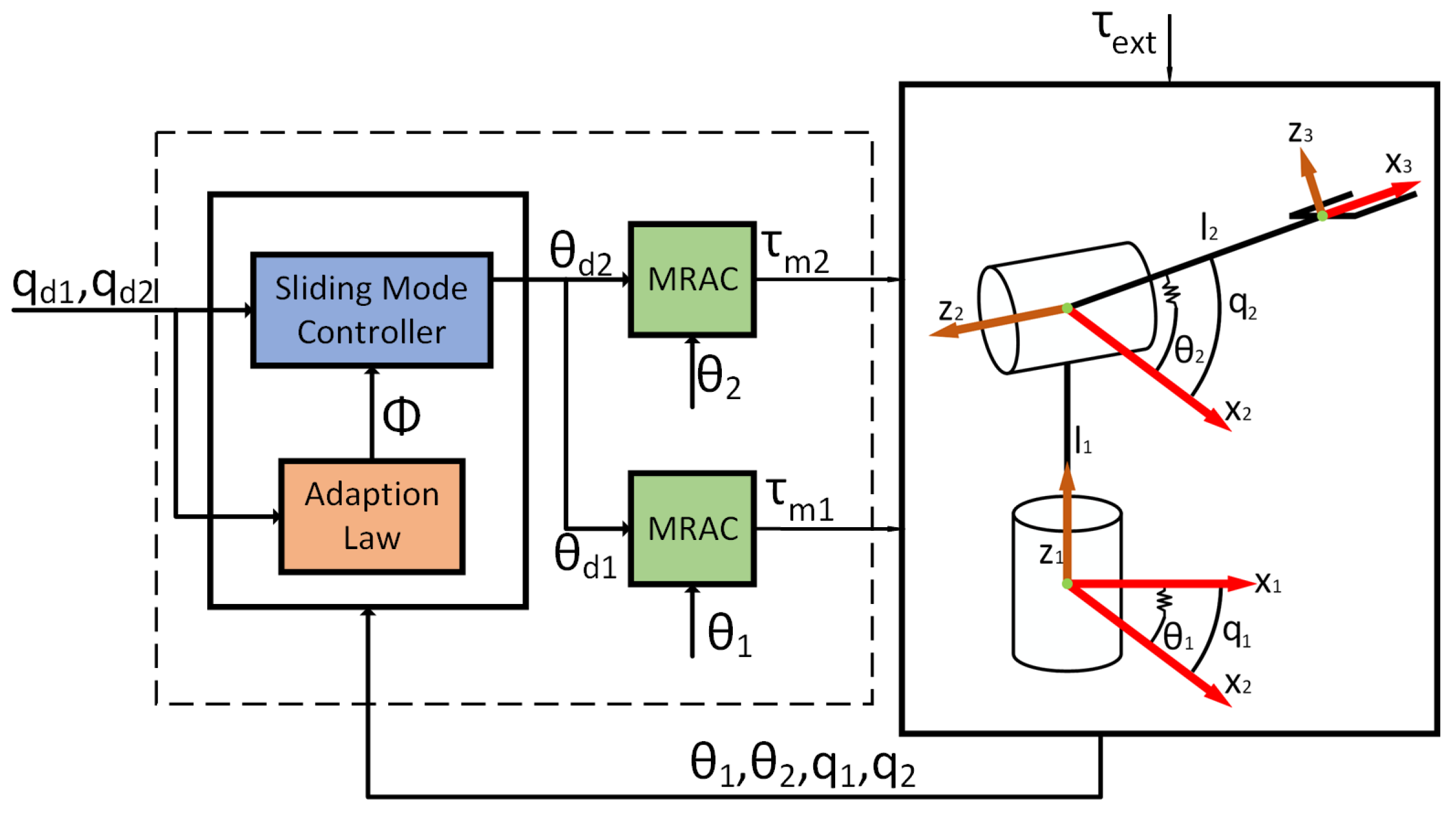
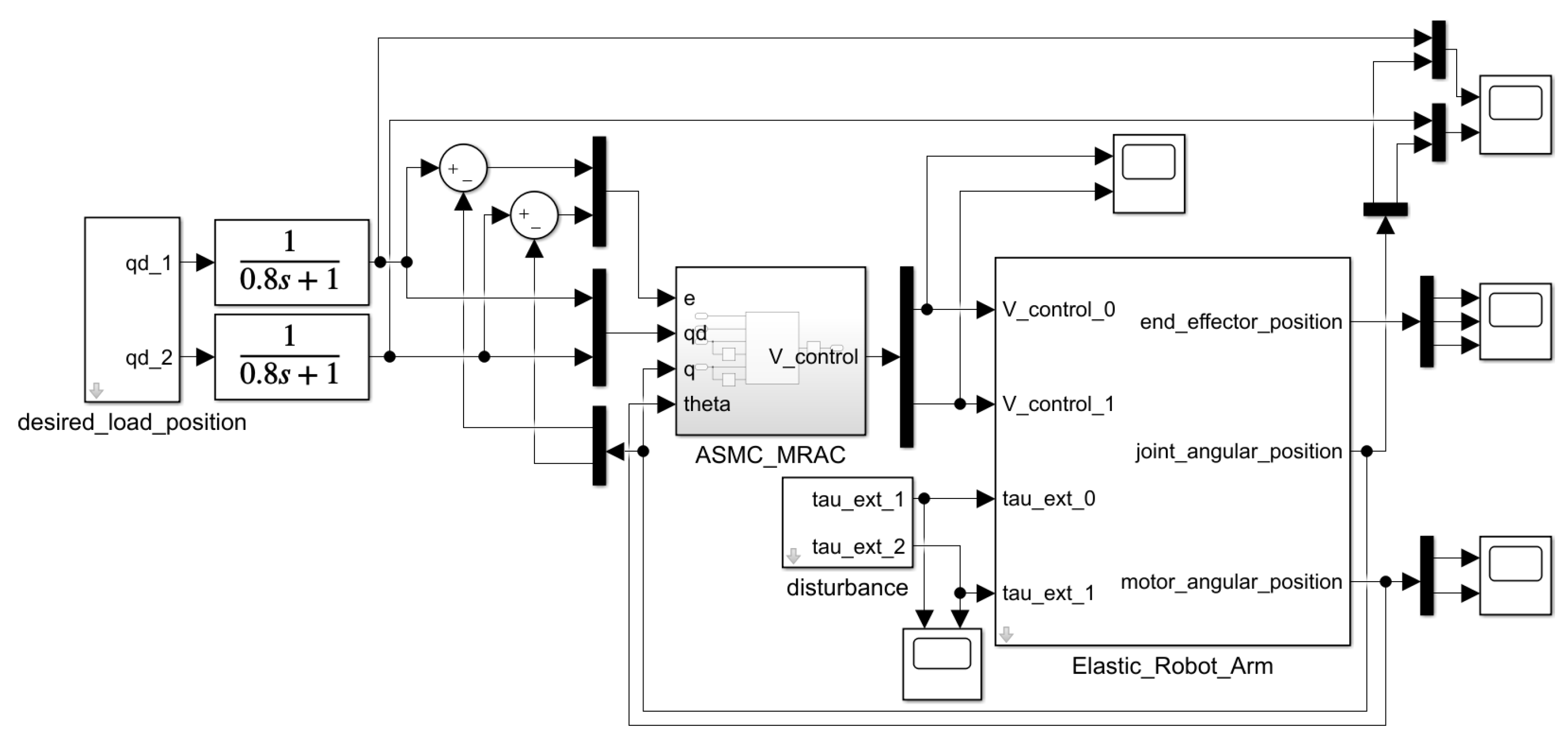
  • An adaptive control mechanism is proposed to deal with the controlling task of a 2-DOF elastic robot arm. The control mechanism has two loops. The outer loop is an adaptive sliding mode controller (ASMC) to deal with uncertainties and disturbances on the load side of the robot arm. The output of this loop is the desired angular position of the motors. The inner loop consists of the model reference adaptive controllers (MRAC) to stabilise the motor side of the robot arm;
  • Extensive simulation experiments and a comparison with the conventional sliding mode controller are conducted to demonstrate the effectiveness of the proposed controller.
The following is a breakdown of the paper’s structure. Section 2 provides an overview of relevant studies. The mathematical model of the considered 2-DOF robot arm with elastic actuators is described in Section 3. Then, the proposed controller is presented in Section 4. To verify the efficiency of the controller, related simulation results are outlined in Section 5. Finally, conclusions and future works are discussed in Section 6.

2. Related Research Work

Elastic actuators and elastic robots are applied in various applications, which are summarised in Table 1. In Reference [6], NASA Valkyrie [7], a humanoid robot with series elastic actuators, is applied for deployment in improvised explosive devices (IEDs) response. In Reference [8], a series-elastic actuated snake robot is proposed, which is able to navigate in pipe bends and junctions. Elastic actuators are also adopted in rehabilitation robots [9,10,11].
There is much research related to the control algorithm of elastic actuators and elastic robots. One of the earliest pieces of research utilises feed-forward terms and a proportional integral derivative (PID) control loop [15]. In Reference [16], by combining the adaptive back-stepping and the dynamic surface control techniques, an adaptive fuzzy output feedback control approach is developed. In Reference [17], a cascade robust control mechanism is introduced. The robustness is proved by L2-gain attenuation from the disturbance caused by uncertainties to performance for the outer loop, and by Lyapunov’s second method for the inner loop. In Reference [18], the synthesis of robust controllers, based on H loop shaping and μ -synthesis for both position control and vibration damping in a spatial flexible L-shape mechanism with gravity, is proposed. In [19], a feedback control law and an observer are proposed based on the finite-element method and model reduction. Regarding robustness, among the methods of control, a sliding mode controller (SMC) is a simple approach, which exhibits stability against parameter variations, unmodelled dynamics and external disturbances [20]. In [21], a hierarchical non-singular terminal SMC is proposed, which can ensure a faster convergence rate of the systems states to zero within a finite time and is singularity free. In Reference [22], a voltage-based SMC is proposed, which has a low computational volume. Despite the inherent advantages of robustness compared to the disturbances, the performance of SMCs can be affected by changing the system parameters [23]. Therefore, adaptive sliding mode controllers (ASMCs) are also commonly considered. In Reference [24], the adaptive fuzzy sliding mode controller is proposed to stabilise the attitude of the flexible satellite. In Reference [25], a fuzzy adaptive sliding mode-based feedback linearisation controller is proposed. A feedback linearisation approach is utilised to change the nonlinear dynamics to a linear dynamics; then, a sliding mode control strategy is implemented as a trajectory tracking controller. A fuzzy system is applied to regulate the controller gains. In Reference [26], a voltage-based sliding mode controller is combined with an adaptive estimator. However, a controller that can deal with uncertainties at the load side and the motor side at the same time is still missing.
To address these challenges, our research group previously presented a two-loop feedback controller [27]. Then, in Reference [28], we compared this controller and a reinforcement learning algorithm. Then, in Reference [29], we implemented the controller on a two DOFs robot arm with elastic actuators. However, to the best of our knowledge, an adaptive control aiming to both stabilize the system and deal with uncertainties to eliminate the influence of external force/torque has not been released. In Reference [30], we started our research on this aspect and presented some preliminary results. In this paper, we extended our research by presenting more simulation experiments. We also made a comparison with the conventional sliding mode controller to show the effectiveness of the proposed algorithm.

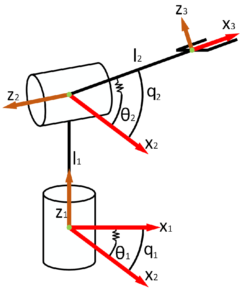
3. Mathematical Model of the 2-DOF Elastic Robot Arm

The mathematical model of the 2-DOF robot arm with elastic joints is introduced in this section.
The diagram of the 2-DOF robot arm with elastic joints is shown in Figure 1. Based on this diagram, the Denavit–Hartenberg (DH) parameters are shown on Table 2, where d is the offset along the z-axis to the common normal, θ is the angle about the z-axis, from the old x-axis to new x-axis, a is the length of the common normal, and α is the angle about common normal, from old z-axis to new z-axis.
Denote q = [ q 1 q 2 ] T and θ = [ θ 1 θ 2 ] T as the load side and the motor side angular positions, respectively. The elastic robot arm in this paper is modelled as a two-side system: the load side system and the motor side system. They are attached to each other by the torque of the spring. The dynamic equations of the robot arm are shown in Equations (1) and (2):
M ( q ) q ¨ + C ( q , q ˙ ) q ˙ + G ( q ) K s ( θ q ) = τ e x t
J θ ¨ + K s ( θ q ) = τ m
where M ( q ) is the mass matrix, C ( q , q ˙ ) is the Coriolis and centrifugal torque matrix, G ( q ) is the gravitational torque vector, K s is the diagonal matrix of spring stiffness, J is the inertia matrix of the motors, τ e x t is the external torque, and τ m is the motor torques. The dynamics of the load side and motor side are presented in Equations (1) and (2), respectively. Equation (1) has the form of a typical robotic dynamic model. The difference is that, instead of the motor torque, the load side is controlled by an elastic force K s ( θ q ) . This elastic force is created from the motor torque by creating a deviation between motor ( θ ) and load (q) angular positions. This is shown in the Equation (2).

4. Controller Design

In this Section, the proposed control algorithm is presented.
The diagram of the proposed controller is shown in Figure 2. The proposed controller has two loops. In the outer loop, the centralised ASMC is implemented to tackle uncertainties and disturbances. In the inner loop, there is one MRAC for each joint to stabilise the motor side. The MRAC was presented in our previous papers [27,29]. Firstly, the conventional sliding mode controller is established. Rewrite Equation (1) as follows:
q ¨ = M ( q ) 1 C ( q , q ˙ ) q ˙ + G ( q ) + M ( q ) 1 K s ( θ q ) = A ( q , q ˙ ) + B ( q ) 1 ( θ q )
where A ( q , q ˙ ) = M ( q ) 1 C ( q , q ˙ ) q ˙ + G ( q ) , B ( q ) = K s 1 M ( q ) and B ( q ) 1 = M ( q ) 1 K s .
The tracking error is defined as:
e = q d q
where q d = ( q d 1 q d 2 ) T is the desired load position vector.
The sliding surface is defined with the PID form as:
σ = e ˙ + K p e + K i 0 t e d t
in which,
K p = K p 1 0 0 K p 2 , K i = K i 1 0 0 K i 2
with K p 1 , K p 2 , K i 1 , K i 2 > 0 as design parameters that need to be suitably tuned so that the characteristic polynomials are strictly Hurwitz [31,32,33]. This ensures that, in the sliding-mode phase, l i m t > e ( t ) = 0 and the system is globally asymptotically stable. The integral term added to the standard PD sliding surface has the effect of eliminating the steady-state error and modifying the reaching time [31,32].
Take the time-derivative of the sliding surface:
σ ˙ = e ¨ + K p e ˙ + K i e = ( q ¨ d + K p e ˙ + K i e ) q ¨ = ( q ¨ d + K p e ˙ + K i e ) + A ( q , q ˙ ) B ( q ) 1 ( θ q )
Denote the control input of the sliding surface in reaching phase as u. Then, the nominal control signal of the sliding mode controller, the desired motor position θ d , is defined as:
σ ˙ = u ( q ¨ d + K p e ˙ + K i e ) + A ( q , q ˙ ) B ( q ) 1 ( θ d q ) = u θ d = B ( q ) A ( q , q ˙ ) + q ¨ d + K p e ˙ + K i e u + q
Next, the adaption law is presented. Although it has many advantages, the conventional sliding-mode controller can not be directly implemented because the real system matrices are unknown. Therefore, an adaptation law is proposed using Lyapunov stability criteria. Denote A ^ ( q , q ˙ ) , B ^ ( q ) as the estimated parameter matrices and rewrite Equation (4) as:
θ d = B ^ ( q ) A ^ ( q , q ˙ ) + q ¨ d + K p e ˙ + K i e u + q
Substituting Equation (5) into Equation (3), we have:
σ ˙ = ( q ¨ d + K p e ˙ + K i e ) + A ( q , q ˙ ) B ( q ) 1 ( θ d q ) = ( q ¨ d + K p e ˙ + K i e u ) + A ( q , q ˙ ) B ( q ) 1 B ^ ( q ) A ^ ( q , q ˙ ) + q ¨ d + K p e ˙ + K i e u + u = B ( q ) 1 ( B ^ ( q ) B ( q ) ) ( q ¨ d + K p e ˙ + K i e u ) + ( B ^ ( q ) A ^ ( q , q ˙ ) B ( q ) A ( q , q ˙ ) ) + u = B ( q ) 1 Φ Φ * Ψ + u
where,
Φ = B ^ ( q ) B ^ ( q ) A ^ ( q , q ˙ )
and
Φ * = B ( q ) B ( q ) A ( q , q ˙ )
are estimated and real system dynamics matrices, respectively, and
Ψ = q ¨ d + K p e ˙ + K i e u 1 .
Denote Δ Φ as the deviation between the real system dynamics matrix Φ * and the estimated system dynamics matrix Φ :
Δ Φ = Φ Φ * .
Then, Equation (6) is as follows:
σ ˙ = B ( q ) 1 Δ Φ Ψ + u
A Lyapunov function is chosen as:
V = σ σ T + B ( q ) 1 Δ Φ Δ Φ T B ( q ) T .
Taking the derivative of the Lyapunov function, we have:
V ˙ = σ ˙ σ T + σ σ ˙ T + B ˙ ( q ) 1 Δ Φ Δ Φ T B ( q ) T + B ( q ) 1 Δ ˙ Φ Δ Φ T B ( q ) T + B ( q ) 1 Δ Φ Δ ˙ Φ T B ( q ) T + B ( q ) 1 Δ Φ Δ Φ T B ˙ ( q ) T = u σ T + σ u T + B ( q ) 1 Δ Φ ( Ψ σ T + Δ ˙ Φ T B ( q ) T + Δ Φ T B ˙ ( q ) T ) + ( σ Ψ T + B ( q ) 1 Δ ˙ Φ + B ˙ ( q ) 1 Δ Φ ) Δ Φ T B ( q ) T .
The time derivative of inertia matrix can be ignored if it is small enough [34]. If the adaption law is chosen as:
Δ ˙ Φ = α σ Ψ T ,
with α as a 2-by-2 matrix of constants; then, V ˙ becomes as follows:
V ˙ = u σ T + σ u T + B ( q ) 1 Δ Φ Ψ σ T ( α T B ( q ) T I ) + ( B ( q ) 1 α I ) σ Ψ T Δ Φ T B ( q ) T .
The following assumptions are made:
Assumption 1.
B ( q ) 1 and Δ Φ are bounded.
Assumption 2.
We can find a matrix α such that B ( q ) 1 α I 0
The matrices B ( q ) 1 and Δ Φ contain trigonometric functions and bounded physical parameters. Therefore, the Assumption 1 is acceptable. In addition, because the matrix B ( q ) 1 is bounded, the Assumption 2 can be satisfied through system parameter estimation and further tuning of the matrix α . From the Assumption 2, V ˙ becomes:
V ˙ = u σ T + σ u T .
Selecting the control input u is a crucial step in designing ASMC. The fundamental control input is the first-order one u = U s i g n ( σ ) , with U as a positive number. Nevertheless, this can cause chattering phenomenon. This phenomenon is the reason for the low control accuracy, high wear of moving mechanical parts, and high heat losses in power electronic boards, as well as the electrical motors [35]. High-order sliding mode control signals were proposed to deal with this [36,37,38]. Although these control signals are able to maintain the sliding mode properties and eliminate the chattering problem [35], more information is demanded by the controller [38]. An r-order sliding-mode controller requires derivatives of the sliding surface up to order r [38]. On the other hand, the “super-twisting” second-order sliding controller, introduced by Levant [37,39], only requires the measurements of the sliding surface. Therefore, the “super-twisting” second-order sliding controller is chosen in this work. This control input is presented as follows:
u = u 1 + u 2 u 1 = U | σ | t a n h ( σ ) u ˙ 2 = 1.1 U t a n h ( σ )
where U is a positive constant, which should be sufficiently large to assure good tracking performance. The term u ˙ 2 = 1.1 U t a n h ( σ ) describes the leakage of the “super-twisting” second-order sliding controller [40]. In addition, the t a n h ( σ ) is used instead of s i g n ( σ ) because it creates a smoother control signal.
By adopting the “super-twisting” second-order sliding algorithm, the term u σ T + σ T u is negative definite [35,41]. Thus, the adaptive system is stable.
In adaptive controllers, disturbances and uncertainties can lead to the parameter drift phenomenon, where the estimated parameters gradually drift before suddenly diverging sharply. To tackle this, a dead zone [42] is added to reduce the influence of the parameter drift phenomenon, therefore increasing the stability of the whole system. This is achieved as follows:
Δ ˙ Φ = B ^ ( q ) 1 σ Ψ T if others 0 if e ( i ) < ϵ e and e ˙ ( i ) < ϵ e d o t , i
where ϵ e and ϵ e d o t are the dead-zone boundary for the errors and the derivatives of the errors.
There are four parameters that need to be tuned in the proposed approach, namely, K p , K i , α and U. A discussion on the effect of these parameters and how to tune them is presented here. K p and K i constitute the sliding surface and affect the convergence of the error. Generally, K p has a role as the proportional gain of a traditional PID controller [43]. Choosing an appropriate value of K p would make the system stable [43]. If the value of K p is too large, the system may be destabilised, and if the value of K p is too small, the system may converge sluggishly [43]. The integral gain K i affects the rates of error integration. In addition, K p and K i have to be chosen such that the characteristic polynomials
s 2 + K p 1 s + K i 1 = 0 s 2 + K p 2 s + K i 2 = 0
with s as the variable in the frequency domain, are strictly Hurwitz [31,32,33]. Many methods have been adopted to choose the parameters for the sliding surface. In this paper, the trial-and-error method is used. Alternative methods are also applied in the literature, e.g., the Ziegler–Nichols method [44], particle swarm optimisation [44], evolutionary algorithms [45], etc.
The parameter α could be chosen such that the Assumption A2 (that is B ( q ) 1 α I 0 ) is satisfied. In practice, the values in matrix B ( q ) 1 can be obtained from the design or the values can be measured. In addition, the angular load positions q have to be operated within a predefined range. Therefore, we can easily estimate the range of matrix B ( q ) 1 and use that to choose the values in α . The value of parameter U is chosen by trial and error. The larger the value of U, the better the tracking performance. However, if the value of U is too large, it could destabilise the system.

5. Simulation

In this Section, simulations implemented in matlab simulink [46] to verify the efficiency of the proposed controller are presented. Figure 3 shows the simulation diagram. Two low-pass filters are added at the input side of the system to smooth the input signal. The simulation parameters are shown in Table 3. The parameters of the proposed approach are shown in Table 4. In addition, to clarify the effectiveness of the proposed controller, it is compared with a conventional SMC-MRAC scheme. Two input signals are used: sine wave and square wave. Furthermore, simulations in disturbed conditions are also presented. There are two types of simulated disturbances: sine wave and square wave. The sine waveform disturbances have a 5-Nm amplitude and 2-Hz frequency. The square waveform disturbances have a 2-Nm amplitude and 0.5-Hz frequency for joint 1, and a 2-Nm amplitude and 0.25-Hz frequency for joint 2. Moreover, a simulation with step input is also presented to analyse the transient and chattering dynamics of the proposed algorithm. In this paper, two specifications are utilised to evaluate the proposed ASMC algorithm: root mean square (RMS) error and total variance of the control signal [47]. The RMS error, which is calculated as
e r m s = 1 N n = 1 N e 2 , N is the amount of sample ,
is used to evaluate the tracking performance [47]. The total variance of the control signal, which is calculated as
Δ T V = n = 1 N | u ( n + 1 ) u ( n ) | ,
is used to evaluate the chattering phenomenon [47]. The RMS errors of the simulations with sine and square wave inputs are presented in Table 5 and Table 6, respectively. The RMS errors and the total variance of the control signal of the simulation with step input is presented in Table 7.

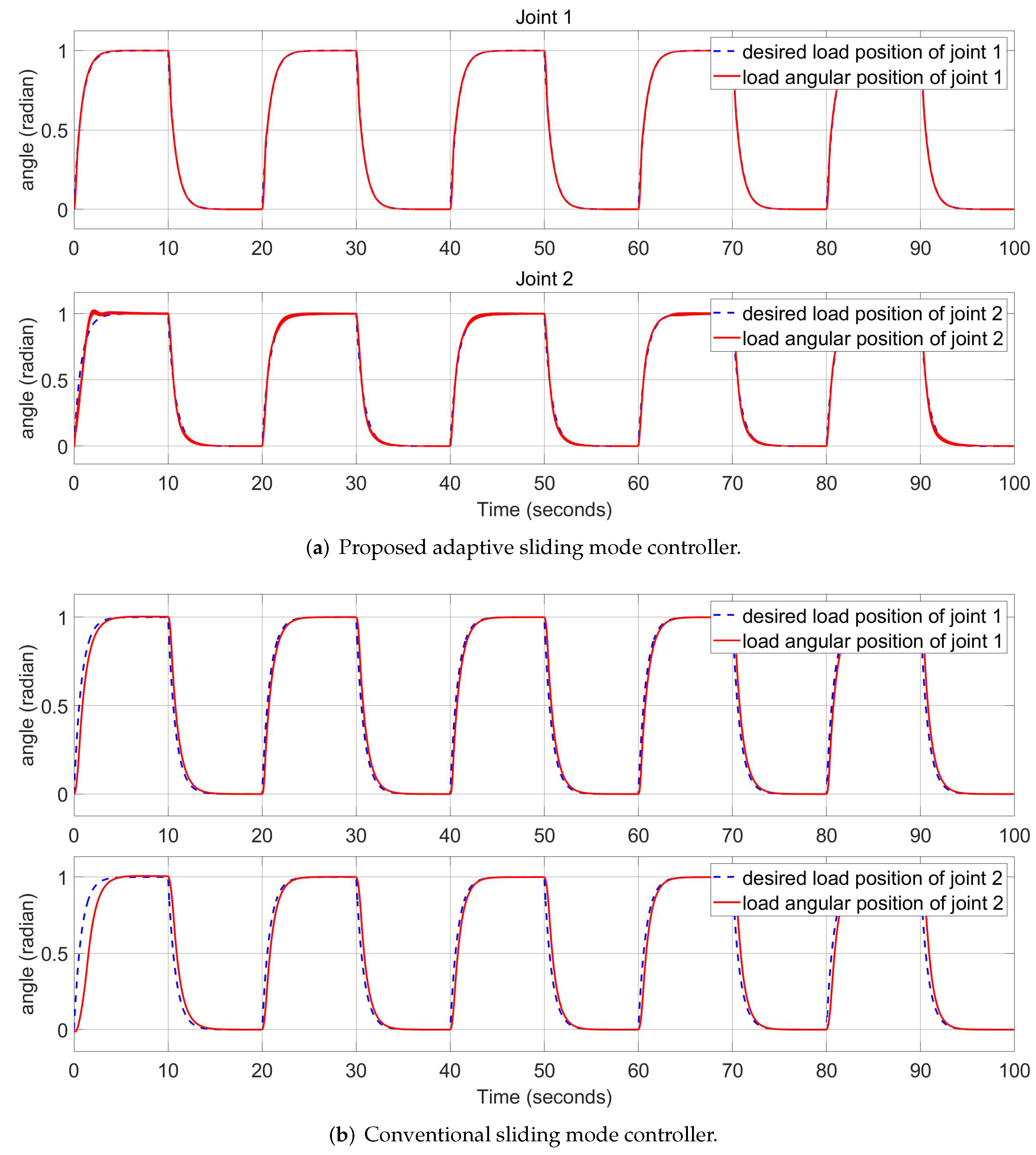
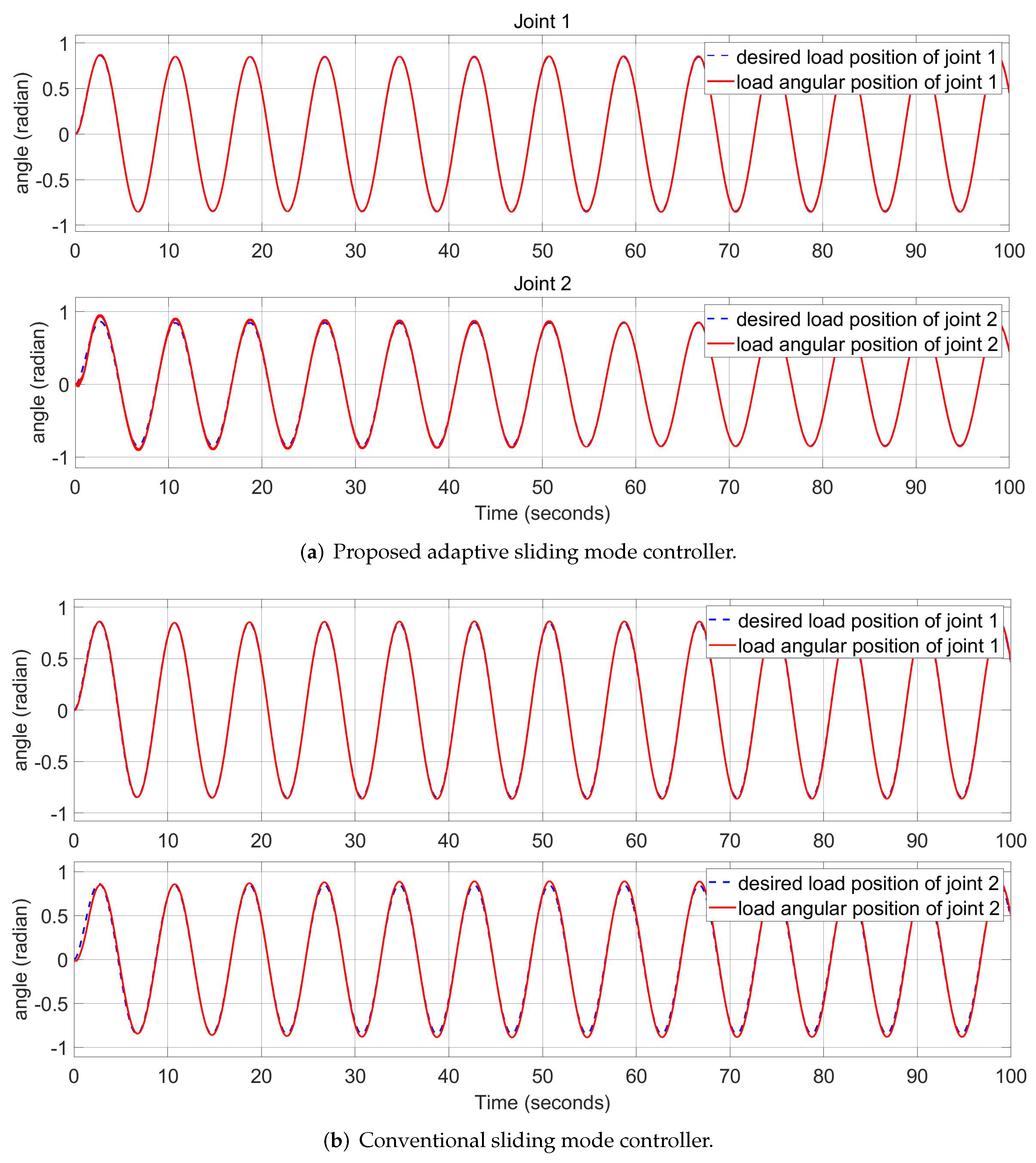
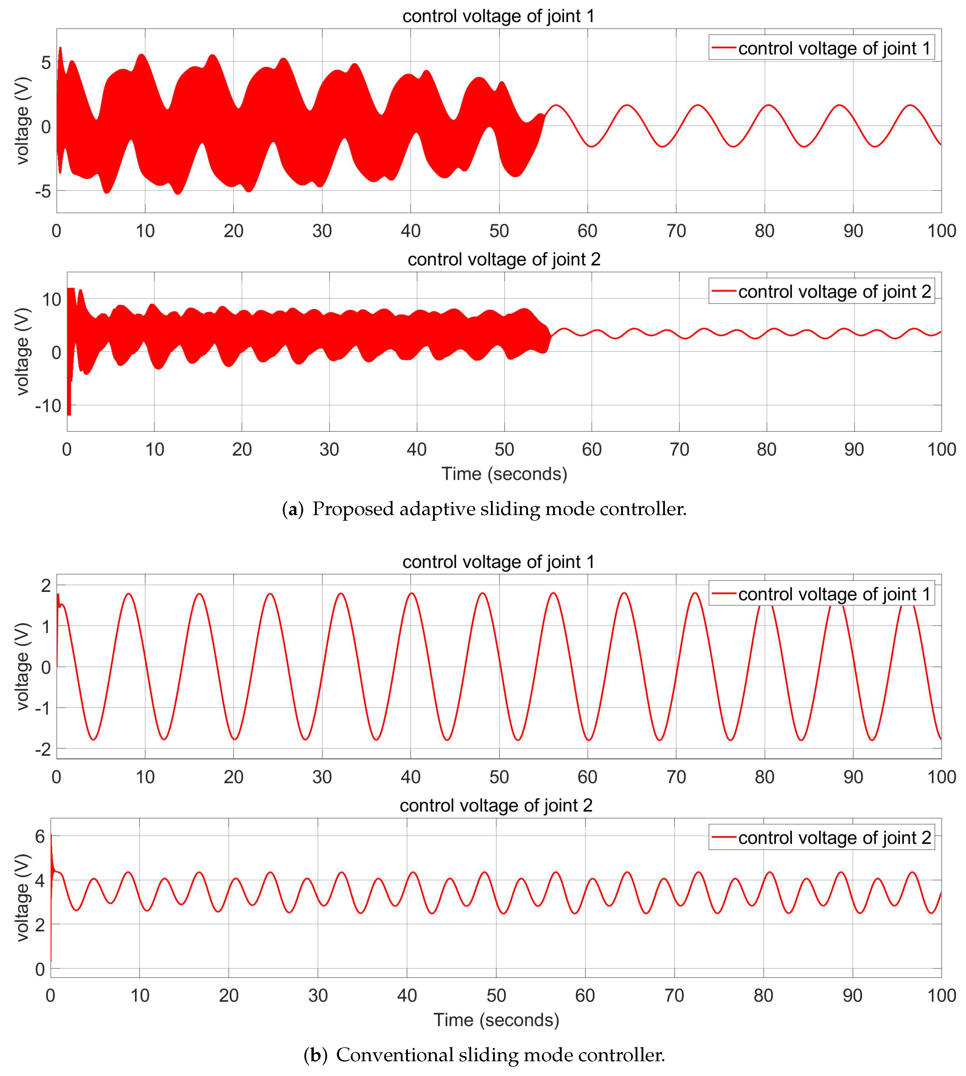
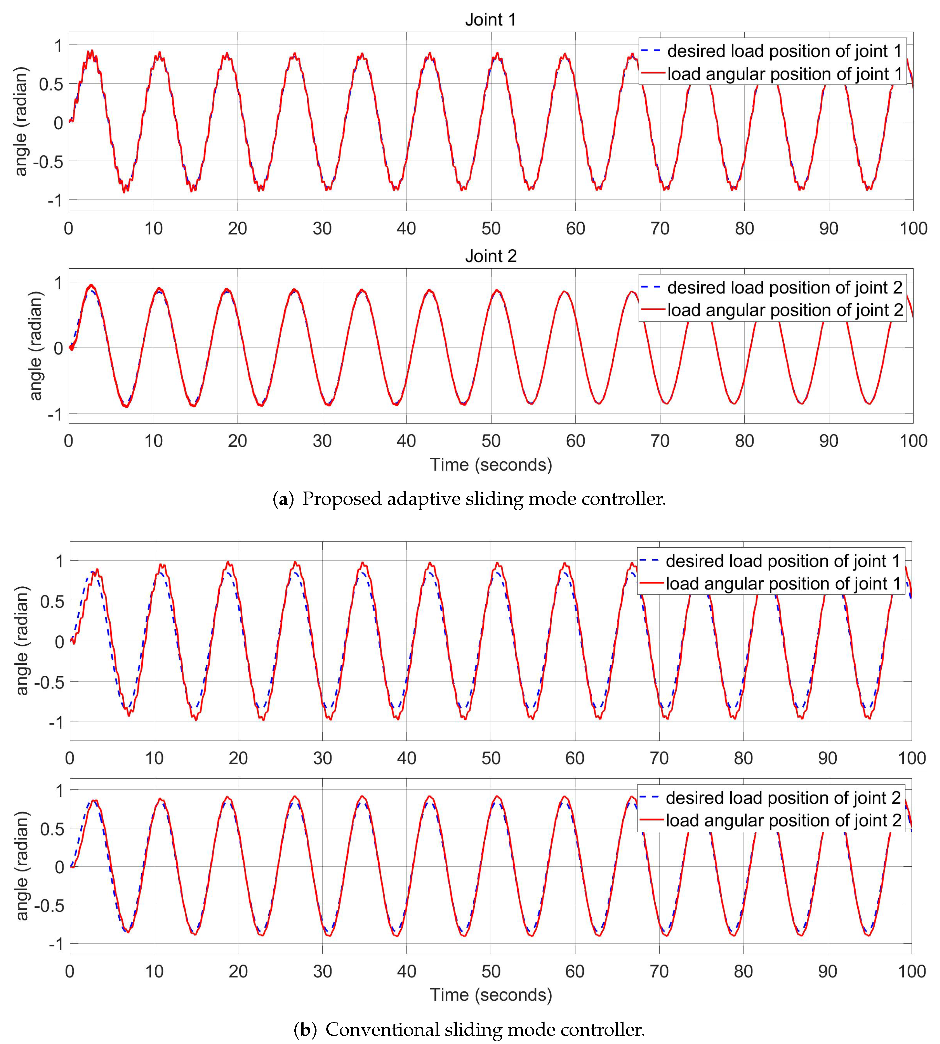
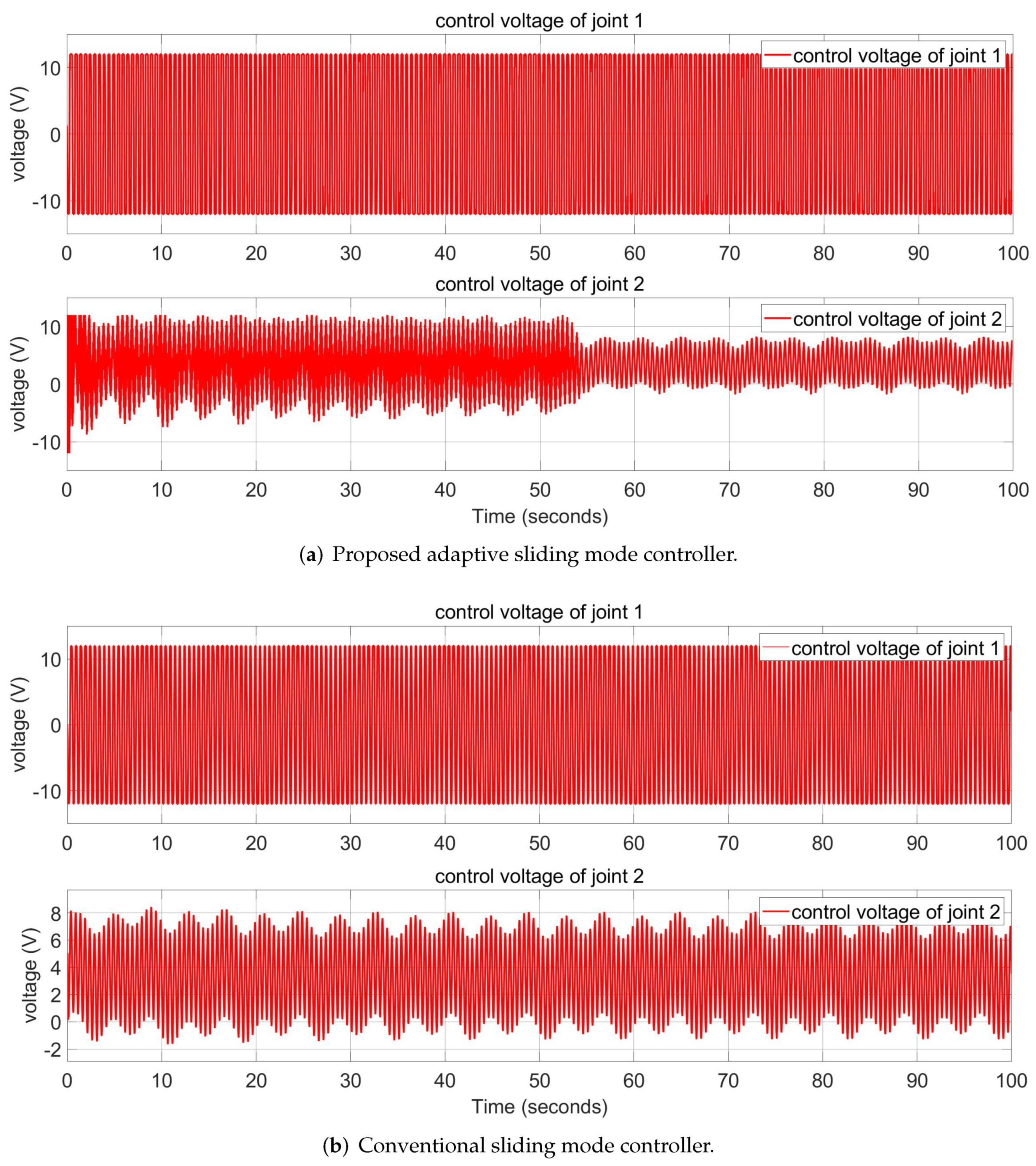
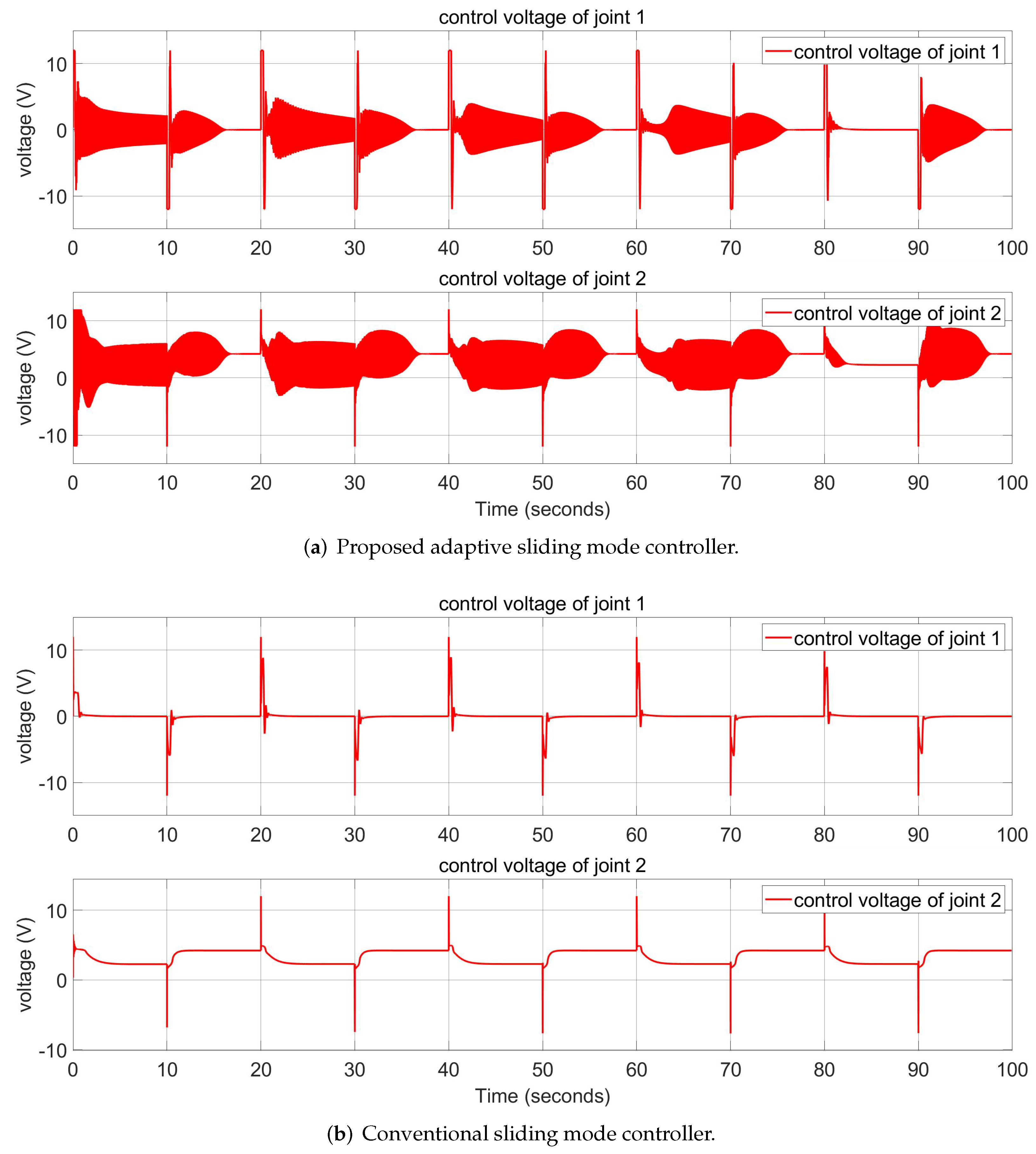
5.1. Sine Wave Input

Figure 4 shows the angular position response of the robot arm in normal condition of the proposed ASMC and the conventional SMC. We can see that the ASMC has a similar quality to a conventional SMC in the normal condition. In Figure 5, the control voltage of the controllers are shown. The fluctuation stage at the beginning in Figure 5a occurs when the ASMC is in the learning phase. After that phase, the ASMC uses the same voltage shape as the SMC for the tracking task.
Figure 6 and Figure 7 show the angular position responses of the robot arm in the disturbed conditions of the proposed ASMC and conventional SMC. They show the systems with the sine wave and square wave disturbances, respectively. It is clear that the ASMC outperforms the conventional SMC in disturbed conditions. Figure 8 and Figure 9 show the control voltage in disturbed conditions with sine wave and square wave disturbances, respectively. After the learning phase, the ASMC uses the same voltage level as the SMC. In addition, the control voltage fluctuates due to the presence of disturbances. As shown in Table 5, the RMS errors of the ASMC are lower than the SMC, implying that the performance of the ASMC is better than the conventional SMC in the simulated cases.

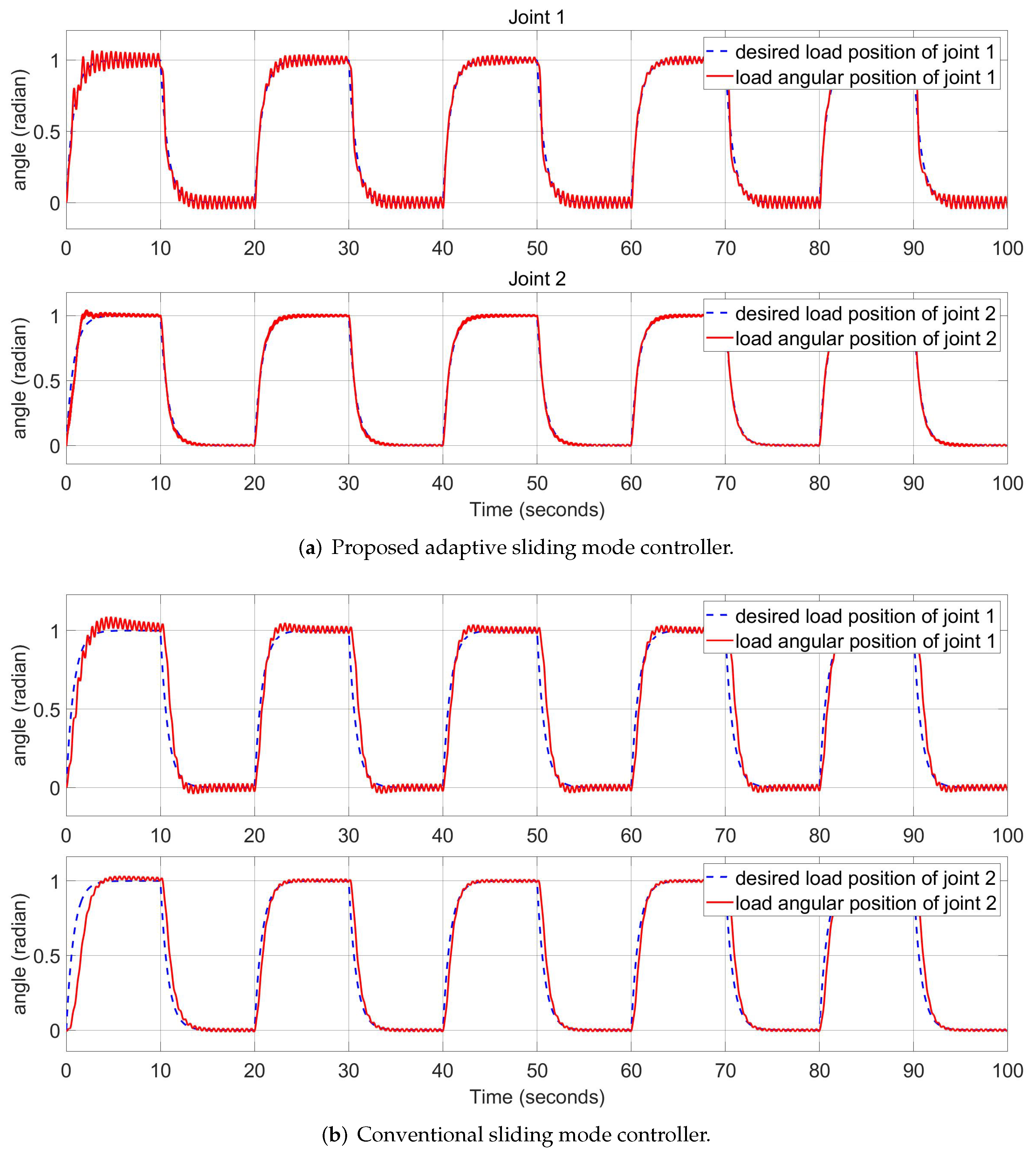
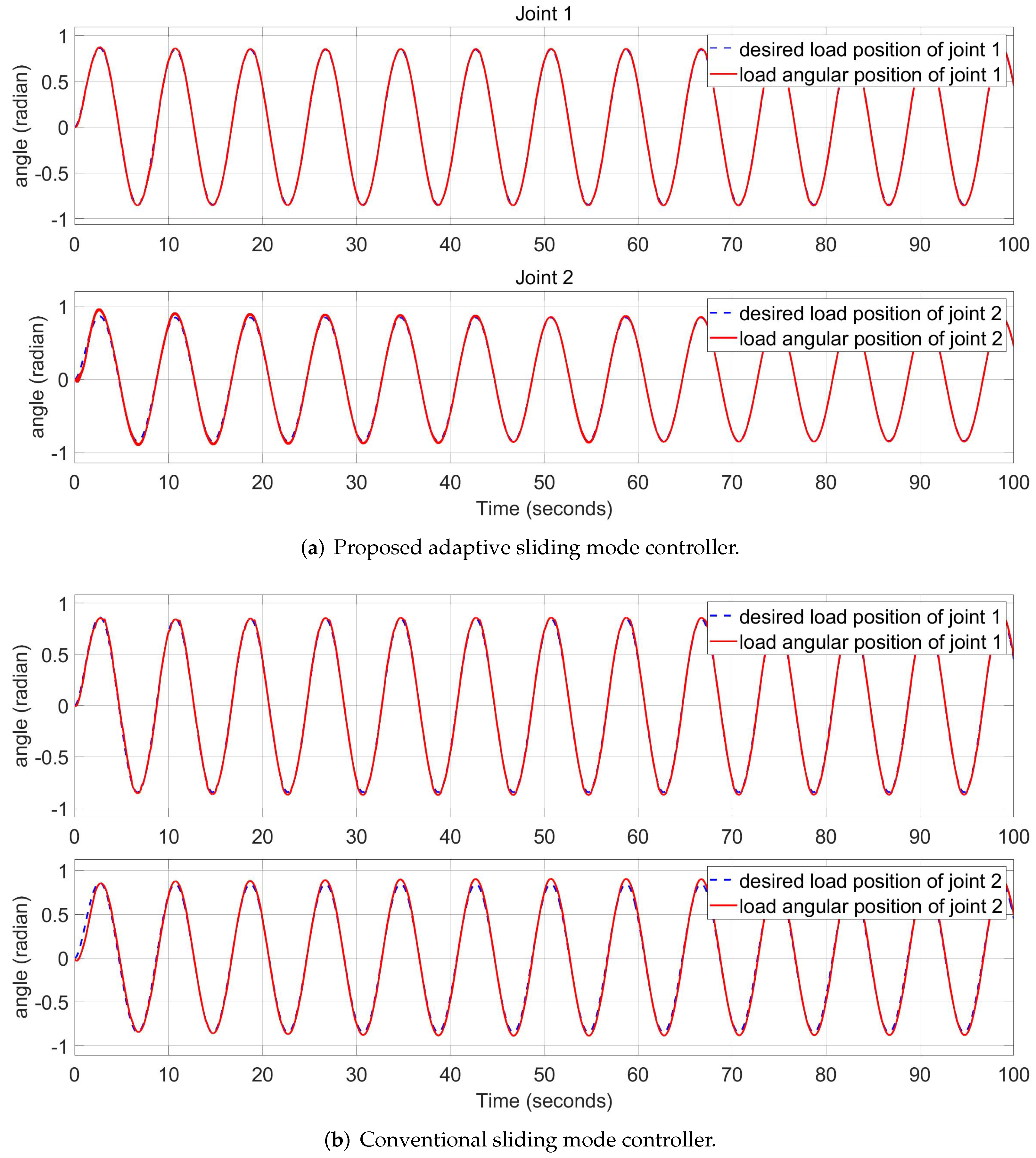
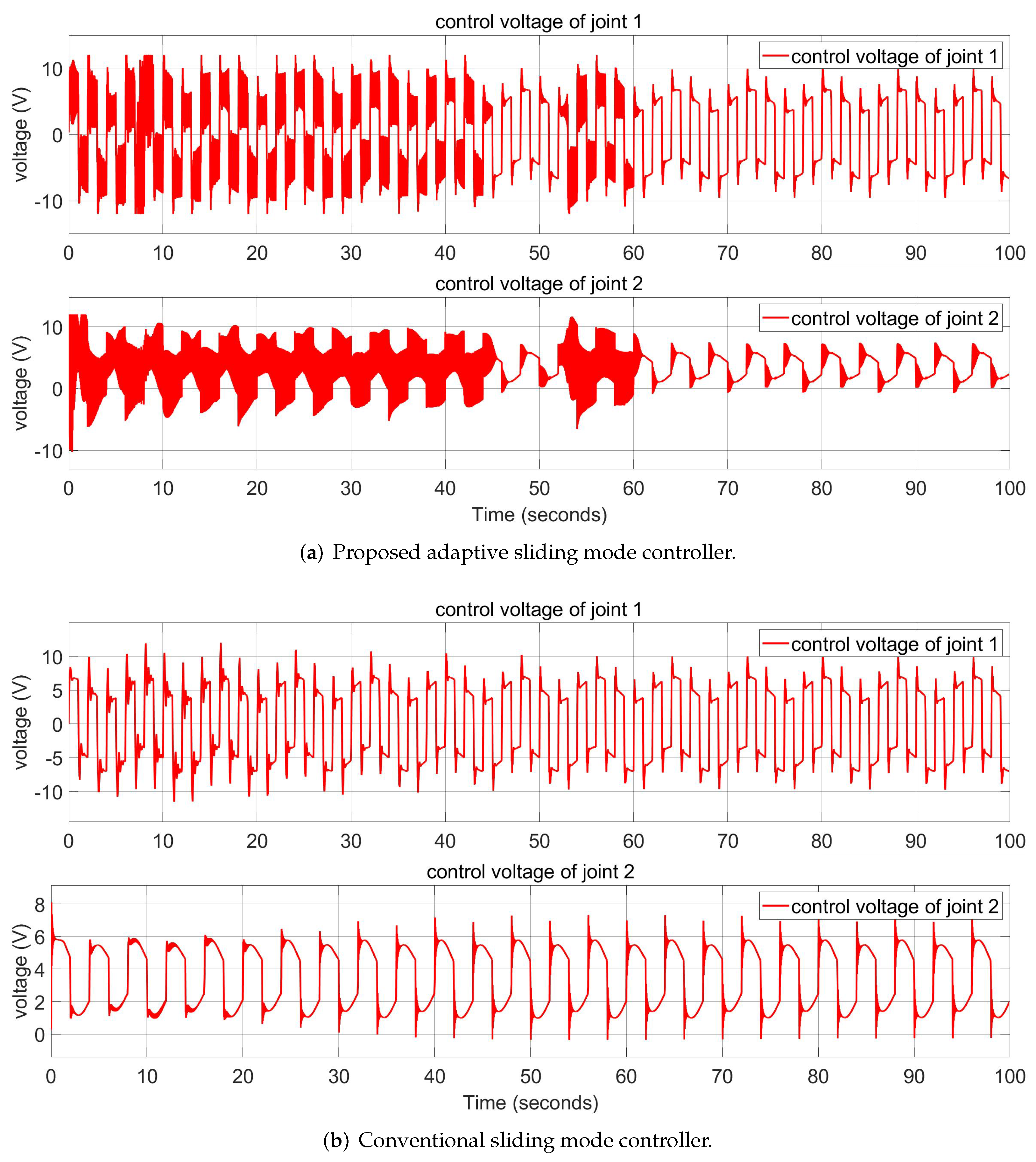
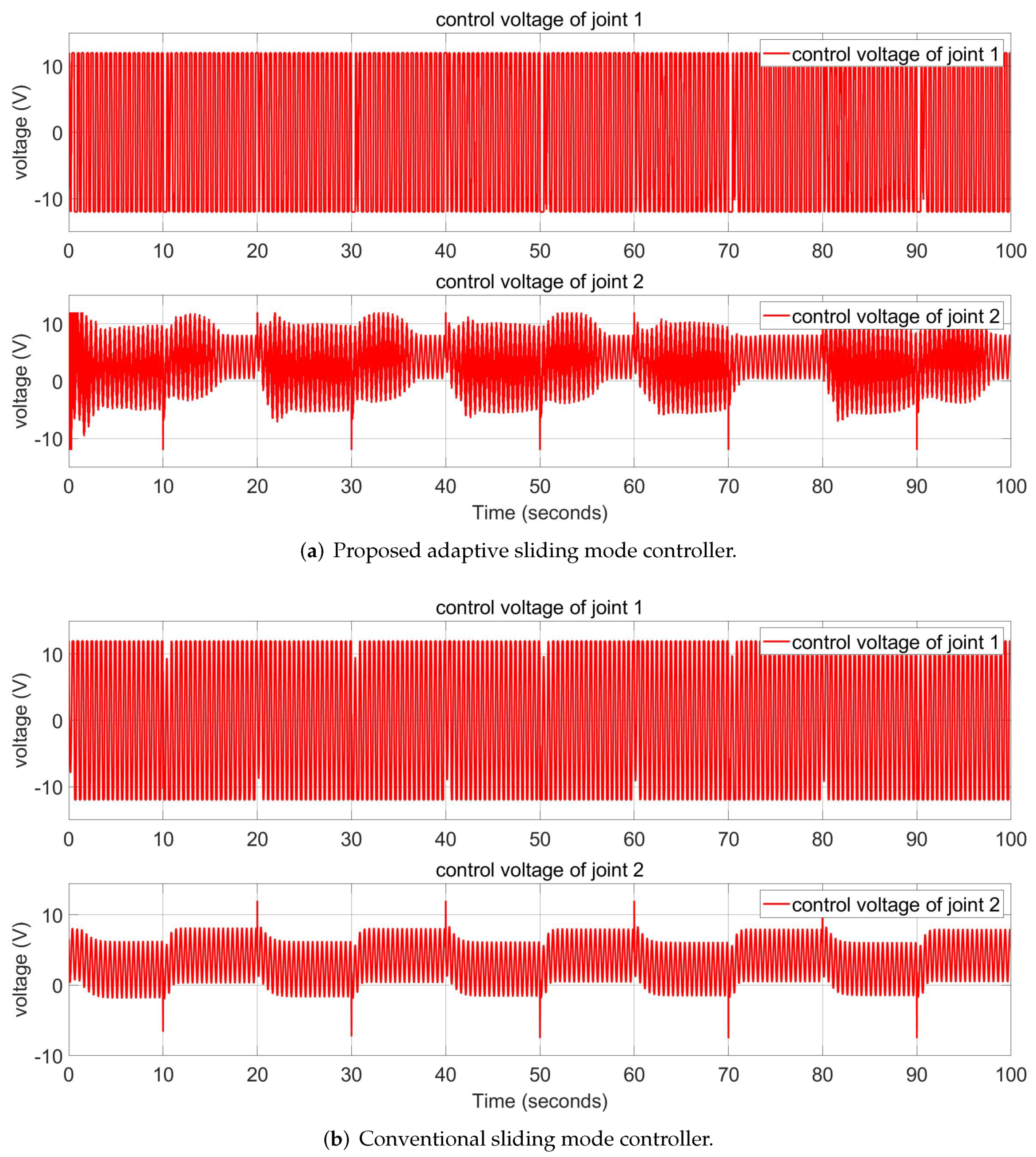
5.2. Square Wave Input
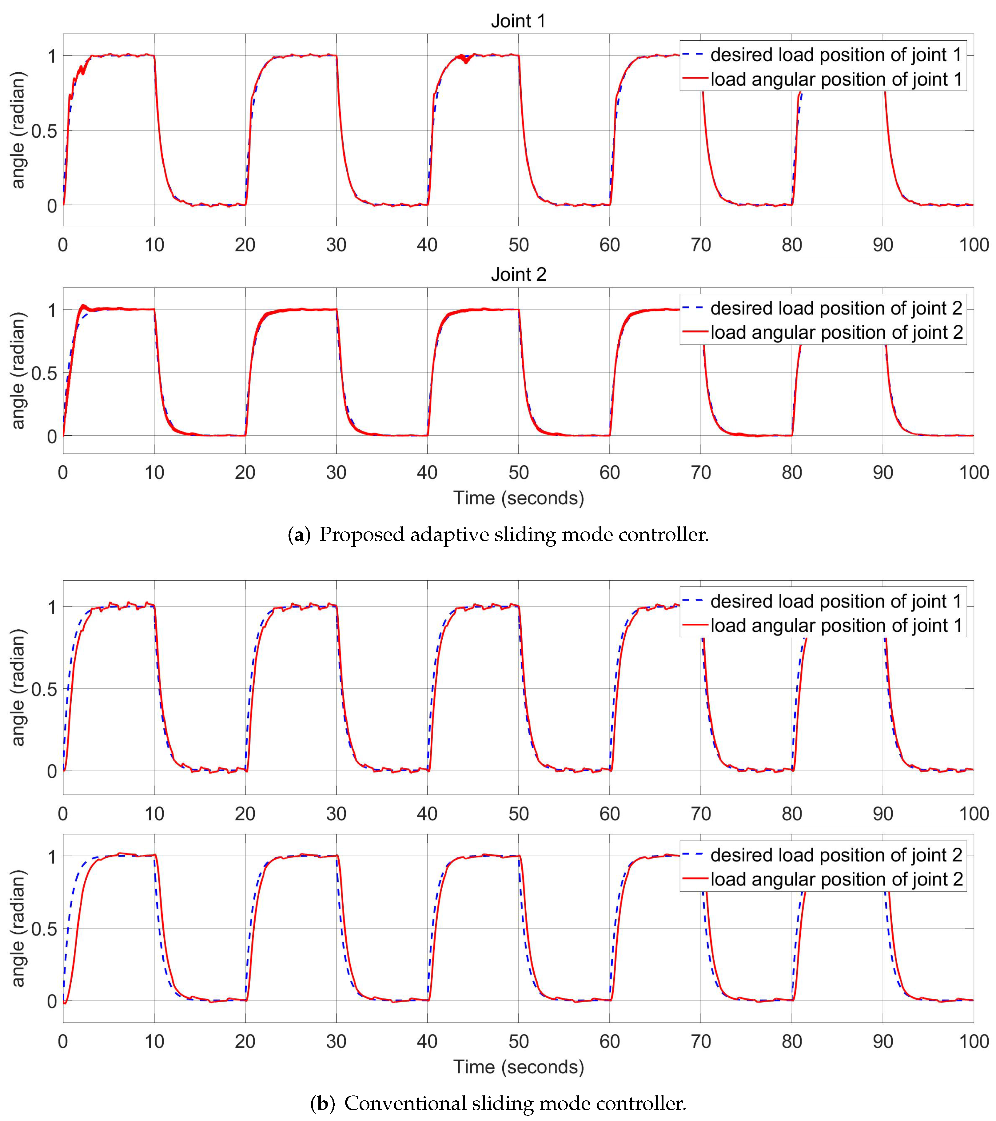
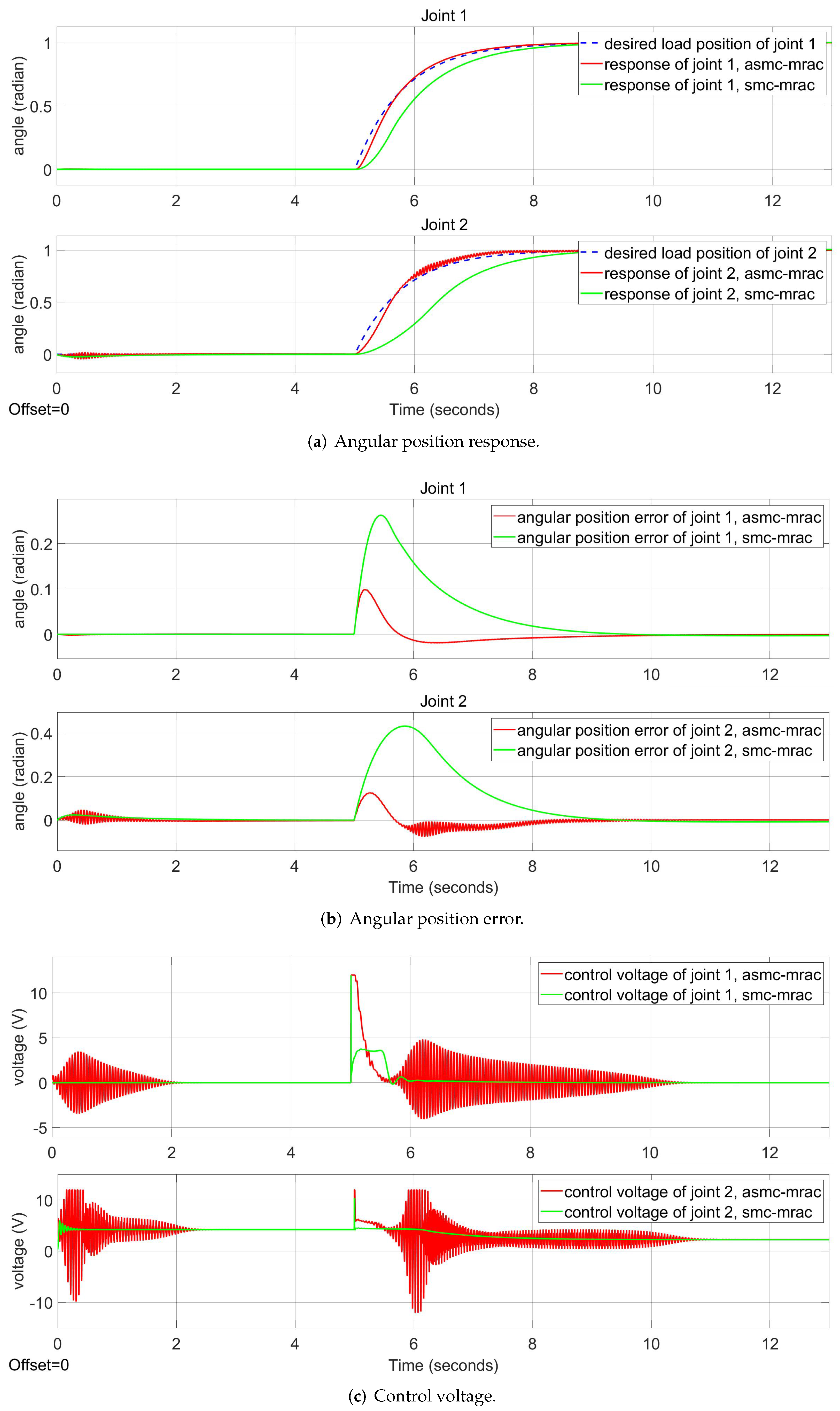
Figure 10 shows the angular position response of the robot arm in normal conditions for the proposed ASMC and conventional SMC with square wave input. The performance of the ASMC improves over time when the adaptive controller can adapt to the system parameters. Overall, after the learning phase, the performance of the ASMC is not inferior to the SMC. Figure 11 presents the control voltage of the two controllers. The ASMC has more voltage fluctuation than the conventional SMC. However, this fluctuation decreases over time.
Figure 12 and Figure 13 show the angular position response of the robot arm in disturbed conditions of the proposed ASMC and the SMC. The systems with sine and square wave disturbances are shown in Figure 12 and Figure 13, respectively. The ASMC has a better tracking performance than the SMC in both cases. The control voltage diagrams of the robot joints are illustrated in Figure 14 and Figure 15. Overall, the control voltage of the proposed ASMC fluctuates more than the conventional SMC. On the other hand, the ASMC has a good tracking performance. This is more clearly indicated through the RMS error in Table 6. The ASMC has a 50.35% lower average RMS error than the SMC controller.

5.3. Step Input

In this section, the simulation with step input and the analysis of the transient and chattering dynamics of the proposed algorithm are introduced. Figure 16 shows the angular position response, error and the control voltage of proposed ASMC and SMC. The RMS error and the total variance in the control signal are shown in Table 7. As illustrated in Figure 16, the ASMC has a better tracking performance than the SMC. The proposed ASMC also has a shorter settling time (5% criterion) than the conventional SMC (0.44 s compared to 2.11 s). However, from the total variance in the control signal in Table 1, the ASMC has a higher chattering phenomenon. The chattering phenomenon can be reduced by decreasing the control parameter U, although this increases the rise and settling time.

6. Conclusions

In this work, we introduced a two-loop controller. To deal with uncertainties and interference on the load side of the robot arm, an adaptive sliding mode controller (ASMC) is proposed in the outer loop. Model reference adaptive controllers (MRAC) are adopted for each joint in the inner loop to address uncertainty on the robot arm’s motor side. The usefulness of the presented ASMC algorithm in stabilising the system in the presence of uncertainties and disturbances is proved through detailed simulated studies. Accordingly, the ASMC has a 50.35% lower average RMS error than the SMC controller. It also has a shorter settling time (5% criterion) (0.44 s compared to 2.11 s). However, this improvement comes at the expense of an increase in the total variance of the control signal.
In the future, the proposed method should be implemented on a real elastic robotic arm. In our previous work [29], a physical 2-DOF robot arm with elastic joints was introduced. We will carry out further empirical experiments on this prototype to demonstrate the effectiveness of the proposed algorithm. In addition, we will expand the controller in the case of robots with an arbitrary number of degrees-of-freedom. Furthermore, we will also address and prove local and global asymptotic stability. The controller could be verified on several types of robots (legged robots, snake robots, etc.). Regarding snake robots, our group is planning to validate the proposed method on Serpens, a highly compliant, low-cost snake robot with series elastic actuators, previously presented in [48,49,50].

Author Contributions

Conceptualisation, F.S., H.M.T. and N.V.H.; methodology, F.S., H.M.T. and N.V.H.; investigation, F.S. and H.M.T.; resources, F.S. and N.V.H.; writing—original draft preparation, F.S. and H.M.T.; writing—review and editing, F.S., H.M.T. and N.V.H.; project administration, F.S.; funding acquisition, F.S. All authors have read and agreed to the published version of the manuscript.

Funding

This research was funded by the Top Research Centre Mechatronics (TRCM), University of Agder (UiA), Norway, https://www.uia.no/en/research/priority-research-centres/top-research-centre-mechatronics-trcm (accessed on 23 March 2022).

Institutional Review Board Statement

Not applicable.

Informed Consent Statement

Not applicable.

Conflicts of Interest

The authors declare no conflict of interest. The funders had no role in the design of the study; in the collection, analyses, or interpretation of data; in the writing of the manuscript, or in the decision to publish the results.

Abbreviations

The following abbreviations are used in this manuscript:
ASMCAdaptive sliding mode controller
MRACModel reference adaptive8controllers
SARSearch and rescue

References

  1. Govindarajan, V.; Bhattacharya, S.; Kumar, V. Human-robot collaborative topological exploration for search and rescue applications. In Distributed Autonomous Robotic Systems; Springer: Tokyo, Japan, 2016; pp. 17–32. [Google Scholar]
  2. Brito, T.; Queiroz, J.; Piardi, L.; Fernandes, L.A.; Lima, J.; Leitão, P. A Machine Learning Approach for Collaborative Robot Smart Manufacturing Inspection for Quality Control Systems. Procedia Manuf. 2020, 51, 11–18. [Google Scholar] [CrossRef]
  3. Mokaram, S.; Aitken, J.M.; Martinez-Hernandez, U.; Eimontaite, I.; Cameron, D.; Rolph, J.; Gwilt, I.; McAree, O.; Law, J. A ROS-integrated API for the KUKA LBR iiwa collaborative robot. IFAC-PapersOnLine 2017, 50, 15859–15864. [Google Scholar] [CrossRef]
  4. Li, W.; Han, Y.; Wu, J.; Xiong, Z. Collision Detection of Robots Based on a Force/Torque Sensor at the Bedplate. IEEE/ASME Trans. Mechatron. 2020, 25, 2565–2573. [Google Scholar] [CrossRef]
  5. Xiao, J.; Zhang, Q.; Hong, Y.; Wang, G.; Zeng, F. Collision detection algorithm for collaborative robots considering joint friction. Int. J. Adv. Robot. Syst. 2018, 15, 1729881418788992. [Google Scholar] [CrossRef] [Green Version]
  6. Jorgensen, S.J.; Lanighan, M.W.; Bertrand, S.S.; Watson, A.; Altemus, J.S.; Askew, R.S.; Bridgwater, L.; Domingue, B.; Kendrick, C.; Lee, J.; et al. Deploying the nasa valkyrie humanoid for ied response: An initial approach and evaluation summary. In Proceedings of the 2019 IEEE-RAS 19th International Conference on Humanoid Robots (Humanoids), Toronto, ON, Canada, 15–17 October 2019; pp. 1–8. [Google Scholar]
  7. Paine, N.; Mehling, J.S.; Holley, J.; Radford, N.A.; Johnson, G.; Fok, C.L.; Sentis, L. Actuator control for the NASA-JSC Valkyrie humanoid robot: A decoupled dynamics approach for torque control of series elastic robots. J. Field Robot. 2015, 32, 378–396. [Google Scholar] [CrossRef]
  8. Rollinson, D. Control and Design of Snake Robots. Ph.D. Thesis, Carnegie Mellon University, Pittsburgh, PA, USA, 2014. [Google Scholar]
  9. Sergi, F.; Lee, M.M.; O’Malley, M.K. Design of a series elastic actuator for a compliant parallel wrist rehabilitation robot. In Proceedings of the 2013 IEEE 13th International Conference on Rehabilitation Robotics (ICORR), Seattle, WA, USA, 24–26 June 2013; pp. 1–6. [Google Scholar]
  10. Chen, T.; Casas, R.; Lum, P.S. An elbow exoskeleton for upper limb rehabilitation with series elastic actuator and cable-driven differential. IEEE Trans. Robot. 2019, 35, 1464–1474. [Google Scholar] [CrossRef]
  11. dos Santos, W.M.; Siqueira, A.A. Impedance control of a rotary series elastic actuator for knee rehabilitation. IFAC Proc. Vol. 2014, 47, 4801–4806. [Google Scholar] [CrossRef] [Green Version]
  12. Tsagarakis, N.G.; Li, Z.; Saglia, J.; Caldwell, D.G. The design of the lower body of the compliant humanoid robot “cCub”. In Proceedings of the 2011 IEEE International Conference on Robotics and Automation, Shanghai, China, 9–13 May 2011; pp. 2035–2040. [Google Scholar]
  13. Sanfilippo, F.; Azpiazu, J.; Marafioti, G.; Transeth, A.A.; Stavdahl, Ø.; Liljebäck, P. A review on perception-driven obstacle-aided locomotion for snake robots. In Proceedings of the 14th International Conference on Control, Automation, Robotics and Vision (ICARCV), Phuket, Thailand, 13–15 November 2016; pp. 1–7. [Google Scholar]
  14. Sanfilippo, F.; Azpiazu, J.; Marafioti, G.; Transeth, A.A.; Stavdahl, Ø.; Liljebäck, P. Perception-driven obstacle-aided locomotion for snake robots: The state of the art, challenges and possibilities. Appl. Sci. 2017, 7, 336. [Google Scholar] [CrossRef]
  15. Williamson, M.M. Series Elastic Actuators. Master’s Thesis, Massachusetts Institute of Technology, Cambridge, MA, USA, 1995. [Google Scholar]
  16. Li, Y.; Tong, S.; Li, T. Adaptive fuzzy output feedback control for a single-link flexible robot manipulator driven DC motor via backstepping. Nonlinear Anal. Real World Appl. 2013, 14, 483–494. [Google Scholar] [CrossRef]
  17. Yeon, J.S.; Yim, J.; Park, J.H. Robust control using recursive design method for flexible joint robot manipulators. J. Mech. Sci. Technol. 2011, 25, 3205–3213. [Google Scholar] [CrossRef]
  18. Barjuei, E.S.; Boscariol, P.; Vidoni, R.; Gasparetto, A. Robust control of three-dimensional compliant mechanisms. J. Dyn. Syst. Meas. Control 2016, 138, 101009. [Google Scholar] [CrossRef]
  19. Thieffry, M.; Kruszewski, A.; Duriez, C.; Guerra, T.M. Control design for soft robots based on reduced-order model. IEEE Robot. Autom. Lett. 2018, 4, 25–32. [Google Scholar] [CrossRef] [Green Version]
  20. Shokoohinia, M.R.; Fateh, M.M. Robust dynamic sliding mode control of robot manipulators using the Fourier series expansion. Trans. Inst. Meas. Control 2019, 41, 2488–2495. [Google Scholar] [CrossRef]
  21. Rsetam, K.; Cao, Z.; Man, Z. Hierarchical non-singular terminal sliding mode controller for a single link flexible joint robot manipulator. In Proceedings of the IEEE 56th Annual Conference on Decision and Control (CDC), Melbourne, VIC, Australia, 12–15 December 2017; pp. 6677–6682. [Google Scholar]
  22. Soltanpour, M.R.; Moattari, M. Voltage based sliding mode control of flexible joint robot manipulators in presence of uncertainties. Robot. Auton. Syst. 2019, 118, 204–219. [Google Scholar]
  23. Tajdari, F.; Kabganian, M.; Khodabakhshi, E.; Golgouneh, A. Design, implementation and control of a two-link fully-actuated robot capable of online identification of unknown dynamical parameters using adaptive sliding mode controller. In Proceedings of the Artificial Intelligence and Robotics (IRANOPEN), Qazvin, Iran, 9 April 2017; pp. 91–96. [Google Scholar]
  24. Guan, P.; Liu, X.J.; Liu, J.Z. Adaptive fuzzy sliding mode control for flexible satellite. Eng. Appl. Artif. Intell. 2005, 18, 451–459. [Google Scholar] [CrossRef]
  25. Mahmoodabadi, M.; Nejadkourki, N. Trajectory Tracking of a Flexible Robot Manipulator by a New Optimized Fuzzy Adaptive Sliding Mode-Based Feedback Linearization Controller. J. Robot. 2020, 2020, 8813217. [Google Scholar] [CrossRef]
  26. Zaare, S.; Soltanpour, M.R.; Moattari, M. Adaptive sliding mode control of n flexible-joint robot manipulators in the presence of structured and unstructured uncertainties. Multibody Syst. Dyn. 2019, 47, 397–434. [Google Scholar] [CrossRef]
  27. Hua, T.M.; Sanfilippo, F.; Helgerud, E. A robust two-feedback loops position control algorithm for compliant low-cost series elastic actuators. In Proceedings of the IEEE International Conference on Systems, Man and Cybernetics (SMC), Bari, Italy, 6–9 October 2019; pp. 2384–2390. [Google Scholar]
  28. Sanfilippo, F.; Hua, T.M.; Bos, S. A comparison between a two feedback control loop and a reinforcement learning algorithm for compliant low-cost series elastic actuators. In Proceedings of the 53rd Hawaii International Conference on System Sciences (HICSS 2020), Maui, HI, USA, 7–10 January 2020. [Google Scholar]
  29. Tuan, H.M.; Sanfilippo, F.; Hao, N.V. Modelling and Control of a 2-DOF Robot Arm with Elastic Joints for Safe Human-Robot Interaction. Front. Robot. AI 2021, 8, 679304. [Google Scholar] [CrossRef]
  30. Tuan, H.M.; Sanfilippo, F.; Hao, N.V. An Adaptive Sliding Mode Controller for a 2-DOF Elastic Robotic Arm. In Proceedings of the 4th International Conference on Intelligent Technologies and Applications (INTAP 2021), Grimstad, Norway, 11–13 October 2021. [Google Scholar]
  31. Tokat, S.; Fadali, M.S.; Eray, O. A classification and overview of sliding mode controller sliding surface design methods. In Recent Advances in Sliding Modes: From Control to Intelligent Mechatronics; Springer: Cham, Switzerland, 2015; pp. 417–439. [Google Scholar]
  32. Khan, A.H.; Li, S. Sliding mode control with PID sliding surface for active vibration damping of pneumatically actuated soft robots. IEEE Access 2020, 8, 88793–88800. [Google Scholar] [CrossRef]
  33. Eker, I. Sliding mode control with PID sliding surface and experimental application to an electromechanical plant. ISA Trans. 2006, 45, 109–118. [Google Scholar] [CrossRef]
  34. Konno, A.; Uchiyama, M. Vibration suppression control of spatial flexible manipulators. Control Eng. Pract. 1995, 3, 1315–1321. [Google Scholar] [CrossRef]
  35. Rivera, J.; Garcia, L.; Mora, C.; Raygoza, J.J.; Ortega, S. Super-twisting sliding mode in motion control systems. Sliding Mode Control 2011, 1, 237–254. [Google Scholar]
  36. Emel’Yanov, S.; Korovin, S.; Levantovskii, L. Higher-order sliding modes in binary control systems. Sov. Phys. Dokl. 1986, 31, 291. [Google Scholar]
  37. Levant, A. Sliding order and sliding accuracy in sliding mode control. Int. J. Control 1993, 58, 1247–1263. [Google Scholar] [CrossRef]
  38. Fridman, L.; Levant, A. Higher order sliding modes. Sliding Mode Control Eng. 2002, 11, 53–102. [Google Scholar]
  39. Levant, A. Robust exact differentiation via sliding mode technique. Automatica 1998, 34, 379–384. [Google Scholar] [CrossRef]
  40. Lee, S.D.; Lee, B.K.; You, S.S. Sliding Mode Control with Super-Twisting Algorithm for Surge Oscillation of Mooring Vessel System. J. Korean Soc. Mar. Environ. Saf. 2018, 24, 953–959. [Google Scholar] [CrossRef]
  41. Moreno, J.A.; Osorio, M. A Lyapunov approach to second-order sliding mode controllers and observers. In Proceedings of the 2008 47th IEEE Conference on Decision and Control, Cancun, Mexico, 9–11 December 2008; pp. 2856–2861. [Google Scholar]
  42. Lavretsky, E. Adaptive control: Introduction, overview, and applications. In Lecture Notes from IEEE Robust and Adaptive Control Workshop; IEEE: Seattle, WA, USA, 9–13 June 2008. [Google Scholar]
  43. Lin, C.H.; Hsiao, F.Y. Proportional-integral sliding mode control with an application in the balance control of a two-wheel vehicle system. Appl. Sci. 2020, 10, 5087. [Google Scholar] [CrossRef]
  44. Soon, C.C.; Ghazali, R.; Jaafar, H.I.; Hussien, S.Y.S. Sliding mode controller design with optimized PID sliding surface using particle swarm algorithm. Procedia Comput. Sci. 2017, 105, 235–239. [Google Scholar] [CrossRef]
  45. Loucif, F.; Kechida, S. Sliding mode control with pid surface for robot manipulator optimized by evolutionary algorithms. In Recent Advances in Engineering Mathematics and Physics; Springer: Cham, Switzerland, 2020; pp. 19–32. [Google Scholar]
  46. MATLAB Version 9.5.0.944444 (R2018b); The Mathworks, Inc.: Natick, MA, USA, 2018.
  47. Furat, M.; İlyas, E. Experimental evaluation of sliding-mode control techniques. Çukurova Üniv. Mühendis.-Mimar. Fak. Derg. 2012, 27, 23–37. [Google Scholar]
  48. Sanfilippo, F.; Helgerud, E.; Stadheim, P.A.; Aronsen, S.L. Serpens, a low-cost snake robot with series elastic torque-controlled actuators and a screw-less assembly mechanism. In Proceedings of the 5th IEEE International Conference on Control, Automation and Robotics (ICCAR), Beijing, China, 19–22 April 2019; pp. 133–139. [Google Scholar]
  49. Sanfilippo, F.; Helgerud, E.; Stadheim, P.A.; Aronsen, S.L. Serpens: A Highly Compliant Low-Cost ROS-Based Snake Robot with Series Elastic Actuators, Stereoscopic Vision and a Screw-Less Assembly Mechanism. Appl. Sci. 2019, 9, 396. [Google Scholar] [CrossRef] [Green Version]
  50. Duivon, A.; Kirsch, P.; Mauboussin, B.; Mougard, G.; Woszczyk, J.; Sanfilippo, F. The new design of Serpens, a highly compliant low-cost snake robot. In Proceedings of the 4th International Conference on Intelligent Technologies and Applications (INTAP 2021), Grimstad, Norway, 11–13 October 2021. [Google Scholar]
Figure 1. Diagram of the elastic robot arm.
Robotics 11 00047 g001
Figure 2. The overall system with a centralised ASMC and two MRACs.
Robotics 11 00047 g002
Figure 3. Simulation on matlab simulink.
Robotics 11 00047 g003
Figure 4. (a,b) Angular position response of the robot arm with sine wave input in normal condition.
Robotics 11 00047 g004
Figure 5. (a,b) Control voltage of the robot joints with sine wave input in normal condition.
Robotics 11 00047 g005
Figure 6. (a,b) Angular position response of the robot arm with sine wave input in disturbed condition with sine wave disturbance.
Robotics 11 00047 g006
Figure 7. (a,b) Angular position response of the robot arm with sine wave input in disturbed condition with square wave disturbance.
Robotics 11 00047 g007
Figure 8. (a,b) Control voltage of the robot joints with sine wave input in disturbed condition with sine wave disturbance.
Robotics 11 00047 g008
Figure 9. (a,b) Control voltage of the robot joints with sine wave input in disturbed condition with square wave disturbance.
Robotics 11 00047 g009
Figure 10. (a,b) Angular position response of the robot arm with square wave input in normal condition.
Robotics 11 00047 g010
Figure 11. (a,b) Control voltage of the robot joints with square wave input in normal condition.
Robotics 11 00047 g011
Figure 12. (a,b) Angular position response of the robot arm with square wave input in disturbed condition with sine wave disturbance.
Robotics 11 00047 g012
Figure 13. (a,b) Angular position response of the robot arm with square wave input in disturbed condition with square wave disturbance.
Robotics 11 00047 g013
Figure 14. (a,b) Control voltage of the robot joints with square wave input in disturbed condition with sine wave disturbance.
Robotics 11 00047 g014
Figure 15. (a,b) Control voltage of the robot joints with square wave input in disturbed condition with square wave disturbance.
Robotics 11 00047 g015
Figure 16. (ac) Angular position response, error and control voltage of proposed ASMC and conventional SMC algorithms.
Robotics 11 00047 g016
Table 1. Applications of elastic actuators.
Type of RobotsHumanoid RobotSnake RobotRehabilitation Robot
ApplicationsNASA Valkyrie [7]
COMAN [12]
POAL [13,14]RiceWrist [9]
ULIX [10]
rotary SEA [11]
Table 2. Denavit-Hartenberg parameters.
d θ a α
Joint 1 l 1 q 1 0 π / 2
Joint 20 q 2 l 2 π / 2
Table 3. System parameters.
ParameterValueParameterValueParameterValue
Gear ratio
( N 1 , N 2 )
10Spring stiffness
( K s 1 , K s 2 )
1500, 1200Load inertia
( J l 1 , J l 2 )
0.1
Load damping coefficient
( D l 1 , D l 2 )
0.2Motor damping coefficient
( D m 1 , D m 2 )
0.027Motor inertia
( J m 1 , J m 2 )
0.003
Motor mass
( m m 1 , m m 2 )
1Link mass
( m l 1 , m l 2 )
6, 4Link length
( l 1 , l 2 )
0.3
Table 4. Parameters of the proposed adaptive sliding mode controller.
ParameterValueParameterValueParameterValue
K p 3 0 0 3 K i 1 0 0 1 α 10 7 × 5 0 0 5
U400 ϵ e π 18 ϵ e d o t π 6
Table 5. The root mean square errors of the angular position response with sine wave input in normal condition and disturbed conditions.
Operating
Condition
Normal
Condition
Sine Wave
Disturbance
Square Wave
Disturbance
Controller Type
ASMC-MRACJoint 10.0099290.0258490.014397
Joint 20.0264020.0266010.029558
SMC-MRACJoint 10.0118130.1025620.017625
Joint 20.0336020.0550170.038218
Table 6. The root mean square errors of the angular position response with square wave input in normal condition and disturbed conditions.
Operating
Condition
Normal
Condition
Sine Wave
Disturbance
Square Wave
Disturbance
Controller Type
ASMC-MRACJoint 10.0131860.0336160.023396
Joint 20.0291230.0289370.031433
SMC-MRACJoint 10.0496050.0910400.058128
Joint 20.0851580.0925270.100103
Table 7. Performance specifications in the simulation with step input.
Performance
Specs
RMS ErrorTotal Variance of
Control Signal
Controller Type
ASMC-MRACJoint 10.0161700.083913
Joint 20.0252500.220392
SMC-MRACJoint 10.0647490.002466
Joint 20.1294570.002836
Publisher’s Note: MDPI stays neutral with regard to jurisdictional claims in published maps and institutional affiliations.

