Abstract
Currently, a large number of investigations are being carried out in the area of robotics focused on proposing solutions in the field of health, and many of them have directed their efforts on issues related to the health emergency due to COVID-19. Considering that one of the ways to reduce the risk of contagion is by avoiding contact and closeness between people when exchanging supplies such as food, medicine, clothing, etc., this work proposes the use of a planar cable-driven parallel robot for the transport of supplies in hospitals whose room distribution has planar architecture. The robot acts in accordance with a procedure proposed for each task to be carried out, which includes the process of disinfection (based on Ultraviolet-C light) of the supplies transported inside the robot’s end effector. The study presents a design proposal for the geometry of the planar cable-driven parallel robots and its end effector, as well as the software simulations that allow evaluating the robot’s movement trajectories and the responses of the position control system based on Fuzzy-PID controllers.
1. Introduction
The use of robots has made it possible to provide numerous solutions in different areas of health care, an example of this being those applications aimed at preventing the transmission of respiratory diseases. Furthermore, a growing number of robot applications with large areas of movement are being applied in logistics, storing, construction, etc. In this section, some research papers that report on these types of applications are summarized.
In the case presented in [1], the public acceptance of autonomous delivery robots (ADR) for last-mile freight deliveries is investigated. This characteristic of contactless distribution can promote mass delivery through these robots. In [2], the use of an autonomous mobile robot guided by GPS for the delivery of packages is proposed, and in [3], a robot that monitors the temperature and the distance of people in public places is presented.
Planar cable-driven parallel robots (CDPR) have also been used as tools for the medical treatment of people. Among the reported works, in [4], a robot equipped with Hall effect sensors is presented, which allows estimating the position in real-time of an endoscopic capsule that moves in the intestine of a person during a clinical procedure. In [5], a reconfigurable planar CDPR is designed for the rehabilitation of the lower extremities in the wrench-closure gait trajectory. In [6], a three degrees-of-freedom (DOF) CDPR is studied in different types of rehabilitation strategies for upper limbs that have lost motor skills due to cardiovascular conditions.
One of the main advantages of planar CDPRs is their ease of adaptation to large vertical work areas, especially those with a flat topology. Considering the approach of the present work that involves movements of the robot on surfaces of hospital buildings, three important aspects to take into account can be highlighted: the implementation in large surfaces of movement, the planning of trajectories and a stage/process of disinfection inside of the end effector (EE). A summary of research papers covering these subjects is presented as follows:
- Implementations in large surfaces of movementIn [7], the use of a scalable robot applied to the construction and/or maintenance of building facades is proposed. The study includes a prototype of the cable-driven robot, a prototype of the wall facade and a prototype of a building. In [8], the design concepts and optimized geometries of a planar CDPR applied to the storage of goods in racks are presented. Simulations of the system are also developed, and the potential use of the robot for precise loading and unloading of containers is analyzed. In [9], a study of logistics robots in the industry is presented, showing a lack of applications based on CDPR. The Technological Readiness Level (TRL) is used as rank index to classify current projects using CDPR in storage applications. The TRL index goes from 1 (for technology in a stage of initial research) to 9 (for technology working in an operational system). For the twelve cases analyzed, the highest TRL rank identified by the authors is 5/6.
- Planning of trajectoriesAn important aspect in robotics is trajectory planning, which can be treated with different approaches. For example, in [10], a distributed route planning method for multiple robots using Lagrangian decomposition technique is proposed, which allows travel of the robots without collision and deadlock. In [11], a space-time network is proposed to map the robot constraints in the route planning framework and to generate collision-free routes of the multi-robot system. On the other hand, in [12], a 6-1-6 polynomial trajectory planner is proposed to allow the movement of a CDPR, which simulates underwater conditions in an underwater humanoid robot.
- Disinfection using Ultraviolet-C lightEfficiency and simplicity have a great influence when choosing the best method for the disinfection of materials. The ultraviolet light disinfection technique has been reported in numerous research papers, some of which describe its characteristics and advantages. In [13], a device with Ultraviolet-C (UV-C) light is used to disinfect mobile phones. The disinfection cycle lasts 30 s, after which a reduction of pathogenic and total bacteria in a range of 90–99% is achieved. In [14], a low-cost sterilizer box using UV light is proposed as protection against COVID-19. In [15], the efficacy between UV-C light, with a wavelength of 254 nm, and pulsed xenon ultraviolet (PX-UV) light, with a wavelength between 100 and 280 nm, is compared in hospital rooms at a distance of 1.2 m from the objective to be disinfected, determining that the UV-C efficiency is greater. Another example can be found in [16], where the design of a device that is placed as a wrist strap is presented for the disinfection of hands and held objects. A control system is integrated into the UV-C emitter head, which regulates the intensity and duration of the UV-C radiation. On the other hand, in [17], a complete study about the advantages and limitations of UV-C radiation applied to the disinfection of foods is presented.
Considering the health emergency caused by COVID-19, in this work, we propose a simulation study for the use of a planar CDPR transporting supplies in hospital buildings whose room layouts allow access from the outside of the facade of the rooms. The proposed robot must follow defined trajectories that will allow linear movement between the supply position and the chosen room position. The system also considers an end effector that performs disinfection using UV-C light during its journey, allowing a reduction in the risk of contagion of the disease. The research major contributions are: a novel use of a known robot topology, the design of an end effector that can disinfect the supplies put inside it by UV light, the programming of the trajectories so that the EE does not rotate, the modeling of the robot dynamics and the wind disturbances acting on the robot.
2. Materials and Methods
2.1. Mechanical Structure of the Proposed Planar CDPR
Figure 1 shows the simplified diagram of the mechanical structure of the proposed planar CDPR. Its fixed structure houses the pulleys that guide the cables that make up the robot’s extremities. The cables are independently connected at one end to an actuator (electric motor) that wind or unwind them according to the requirements of the control system, and at the other end, they are anchored to a mobile structure considered the operating end or end effector of the robot. The labels shown in the mechanism in Figure 1 correspond to:
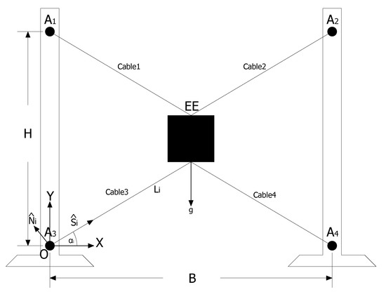
Figure 1.
Simplified scheme of the mechanical structure for the proposed planar CDPR.
- A1, A2, A3 and A4: cable guide pulleys and anchor points on fixed structure;
- EE: end effector;
- B: robot base defined by the horizontal distance between pulleys;
- H: robot height defined by the vertical distance between pulleys.
The origin of the system of axes is at the bottom left of the structure. Vector represents the direction along the i-th cable, represent a normal direction respect to the i-th cable, and is the angle between X-axis and .
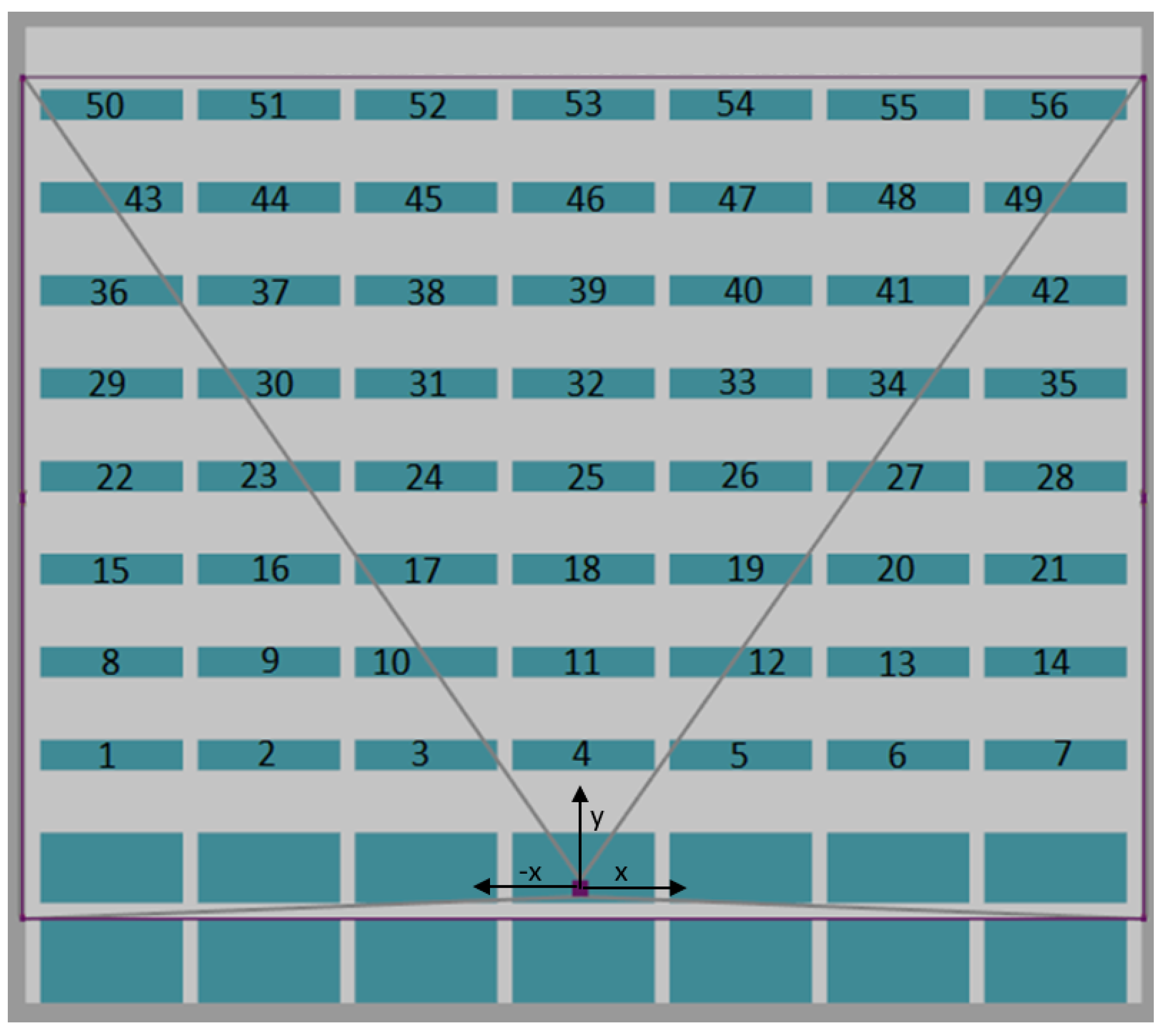
The working area of the robot’s EE can theoretically be considered the area between the ends of the pulley’s support structure; however, in practice, it will be reduced depending on different mechanical and control factors, one of which may be the maximum tension in the cables. The dimensions of the robot are directly related to the dimensions of the facade surface, where the rooms of the health center are located. For this study, a hypothetical case is considered based on one hospital building, which has 10 floors, of which the upper 8 have 7 rooms located cross-wise on the facade. The end effector will have access to 56 rooms, as shown in Figure 2. The dimensions correspond to a base of 40 m by a height of 30 m, and each room has specific coordinates. For example, the room numbered as “6” would have the coordinates [] = [7.125 m, 3.5 m]; meanwhile, the supply point is located in the lower central part of the building and is set as the coordinates origin.
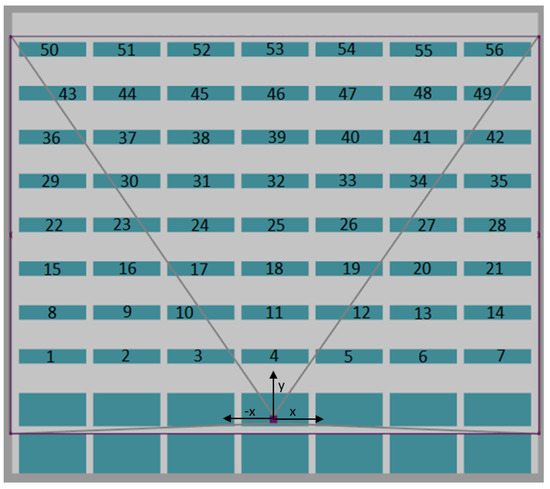
Figure 2.
Scheme of the facade of the hospital building.
Taking into account the tasks that the robot will develop, which include the transport of supplies, food, medicines and clothing, a maximum load capacity of 40 kg was considered. Additionally, an EE weight of 10 kg is considered, which is estimated from the EE design dimensions and considering a structure of light and resistant material, such as injected plastic and aluminum, in addition to the weight of batteries and electronic elements for the LED light, transmission of data and position sensing. The final design of the EE would have an estimated total weight of 50 kg, and the details of its design are given in Section 2.4.
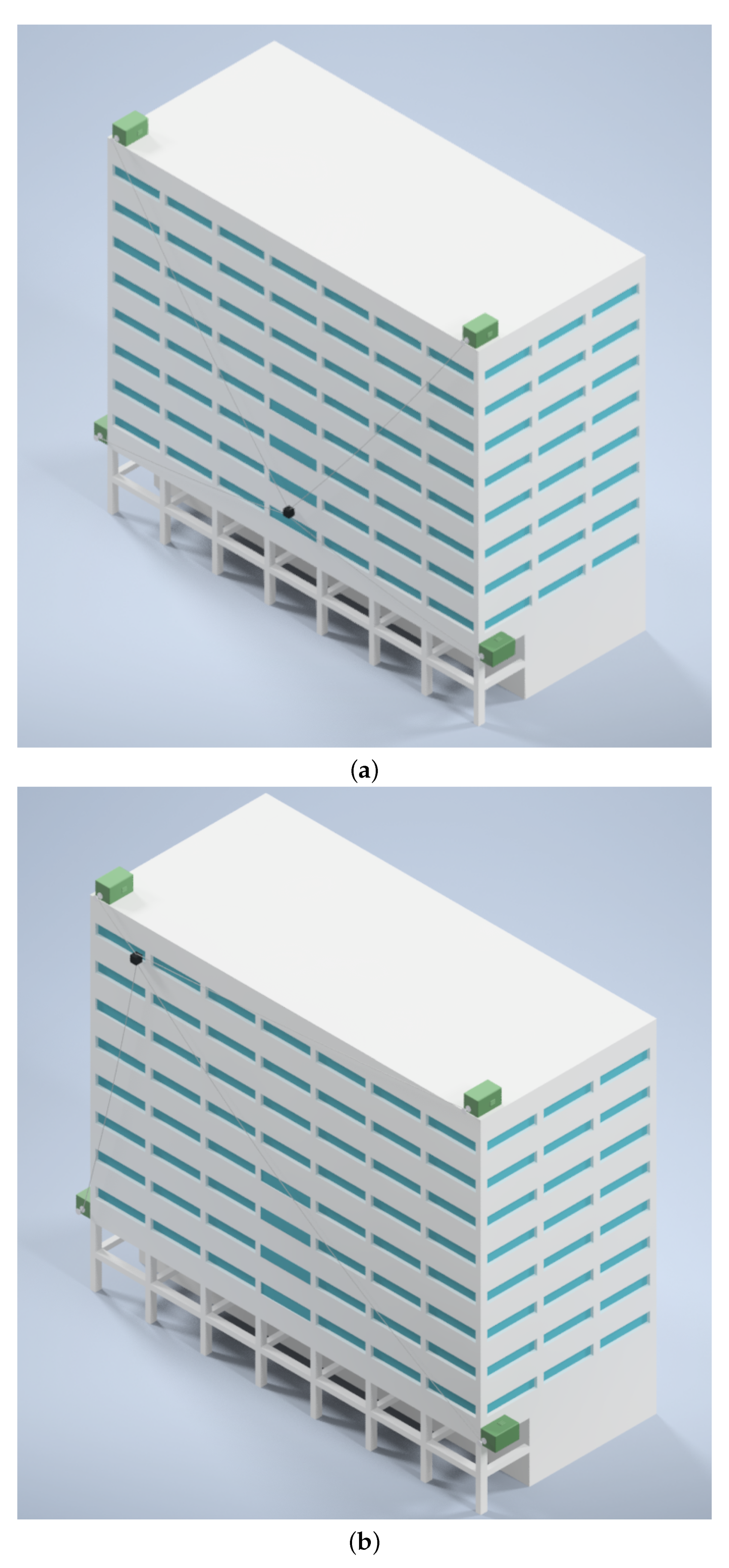
In Figure 3a,b, detailed views of the planar CDPR attached to the facade of the hypothetical hospital building are shown. In each figure, a perspective for different positions of the end effector can be seen, namely: the EE positioning in room 11 in Figure 3a and the EE positioning in room 50 in Figure 3b.
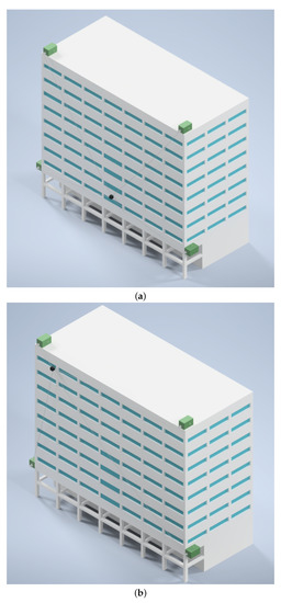
Figure 3.
Detailed views of the planar CDPR attached to the facade of the hospital building. (a) End effector positioning in room 11. (b) End effector positioning in room 50.
To be able to carry out the simulations, the dynamic model of the system is required, in which the external forces in the EE, the weight of the EE, the friction damping forces of the environment where the robot works and the forces developed in the robot cables are taken into account [18,19]. The resulting model is described by Equations (1)–(4), where Equations (1) and (2) describe the forces in axes x and y, respectively, acting on the EE. Inside these equations, the intermediate terms and are defined, which are, in turn, developed in Equations (3) and (4) [18].
where
The different forces applied to the EE correspond to: external forces (, ), gravitational forces (), forces developed in the EE due to its acceleration () and damping forces due to friction in the environment where the robot moves (). The cables are actuated by means of the forces impressed by the actuators. The cables have constant density and are actuated by forces . is the recollection or extension speed, and is the angular speed in each wire. The speed of the cable’s center of mass is composed by a longitudinal component in direction and a normal component in direction .
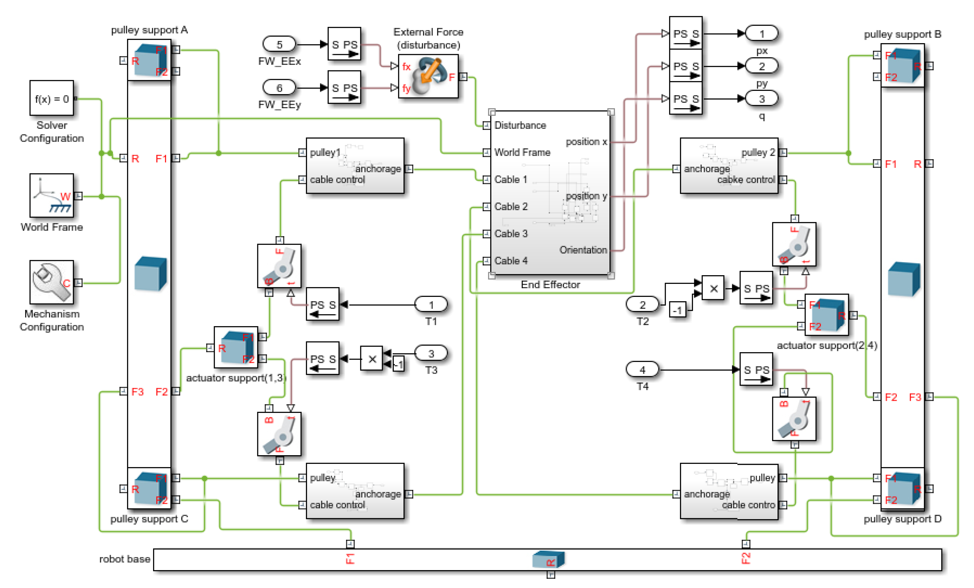
To develop the simulations, the robot has been modeled with MATLAB/Simscape, as shown in the block scheme of Figure 4. This software allows the simulation of mechanisms assembled with physical components available in its library, which includes mechanical properties, such as inertia, friction, the action of gravity, among others. The scheme of the proposed CDPR operating on the facade of the hospital building is depicted in Figure 2. For this exemplary implementation, the coordinates origin is set in the lower central part of the building.
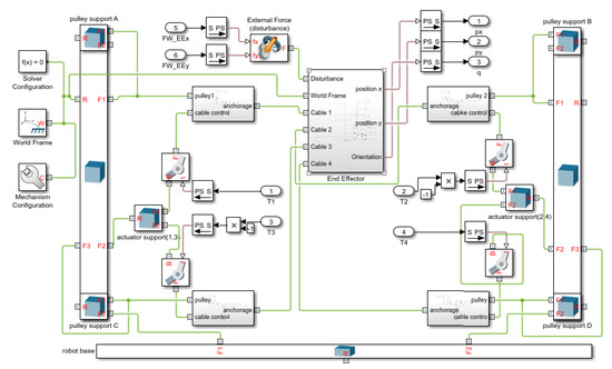
Figure 4.
Block scheme of proposed planar CDPR prototype model implemented in MATLAB/Simscape.
2.2. Position Control Topology
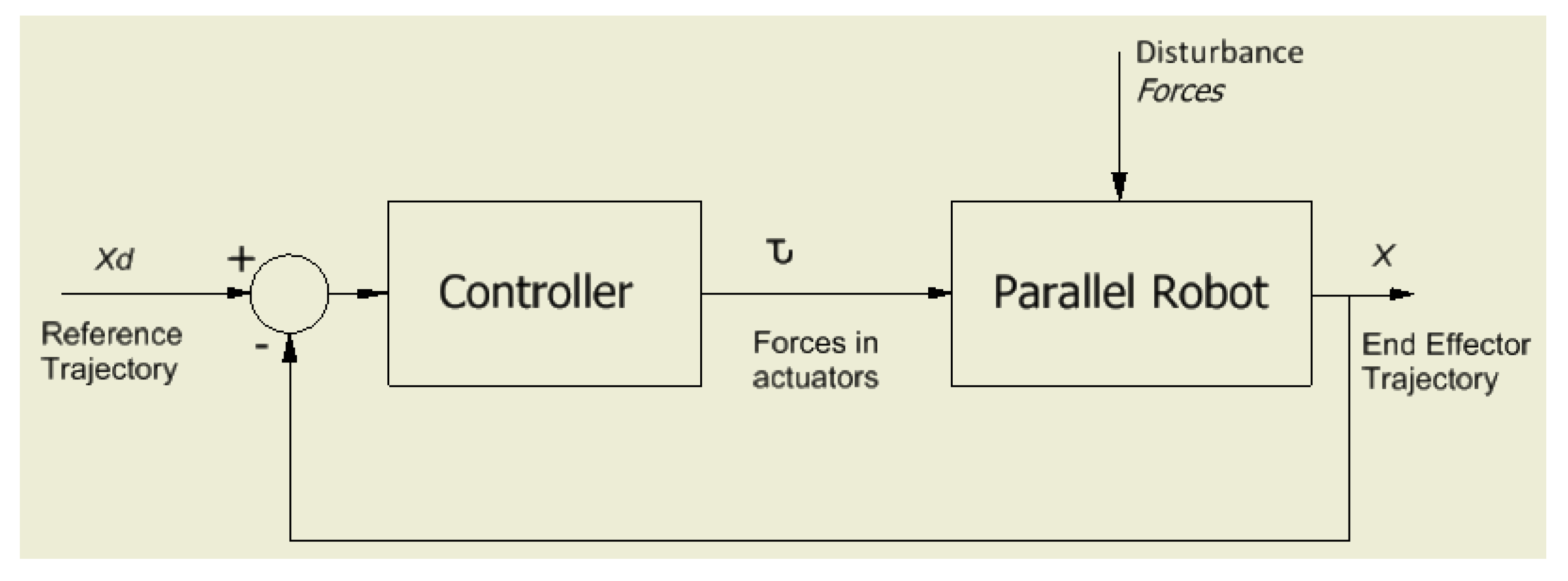
For this application, a position control topology is required [20], which can be treated in two ways: one referring to joint space (by using encoders in the motors and/or in the pulleys) and the other referring to task space (by using absolute position measurements). To ensure the best positioning of the EE, the position control in the task space is used, in which the absolute position of the EE is directly fed back. To measure this position, an inertial measurement unit (IMU) arranged in the EE is proposed, the data of which will be transmitted by a Wi-Fi wireless module. It should be noted that the IMU takes the initial reference values of the robot’s home position as input for the estimation of the absolute position during the movement. This information would be refreshed every time the robot is positioned at home. The general block diagram for the control topology is shown in Figure 5.
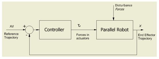
Figure 5.
General scheme for the position control topology for a parallel robot, considering its action in the task space. Adapted from Ref. [19].
Regarding the structures of the control topologies used in robotics, these can be designed as coupled or uncoupled, depending on the feasibility [20,21]. For the case of the CDPR in Figure 1, a decoupled control structure is proposed for each axis of action of the EE [19], and its scheme is observed in Figure 6.
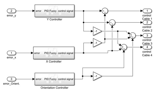
Figure 6.
Block diagram of the implementation in MATLAB/Simulink of the decoupled control structure for the positioning and orientation of the proposed planar CDPR.
2.3. Trajectory Planning
The next aspect to consider in the control design is the trajectory planning, which allows determining the sequence of positions that the robot’s EE will travel and must meet smoothness and continuity requirements [22]. These requirements must also be met by speed, acceleration and jerk functions. Many forms of trajectory planners can be found in the literature, among them are the interpolating polynomials that allow meeting the previous requirements of continuity and smoothness. Considering that the jerk corresponds to the third derivative of the position, its smoothness and continuity will be guaranteed with the choice of polynomials of the fourth order (or higher) in the start and end stages of the trajectory, while, in the central stage, it could be used at the rated speed of the actuators, so a first order polynomial could be chosen. Consequently, the basic and minimum structure of the interpolating polynomials would be a 4-1-4 structure to meet the previously described requirements.
One approach that can be used for planning is the use of the polynomial trajectory 6-1-6 [23], which consists of a polynomial sequence composed of a sixth-order polynomial in the acceleration and deceleration sections, linked with a polynomial of order one in the central section, which guarantees a constant speed. This generic 6-1-6 polynomial structure is represented by equations [12]:
The values are considered along each axis of the robot, being:
- , and : positions reached during the sections of acceleration, constant speed and deceleration, respectively;
- : maximum speed that can be developed;
- : acceleration and deceleration time;
- : total time required to develop the whole trajectory.
The execution time of a trajectory depends on three important aspects:
- Maximum speed to be developed in the EE of the robot, which will be related with the dimensioning of the actuators;
- Time required for the disinfection of the transported supplies;
- Distance between the supply point and the target room.
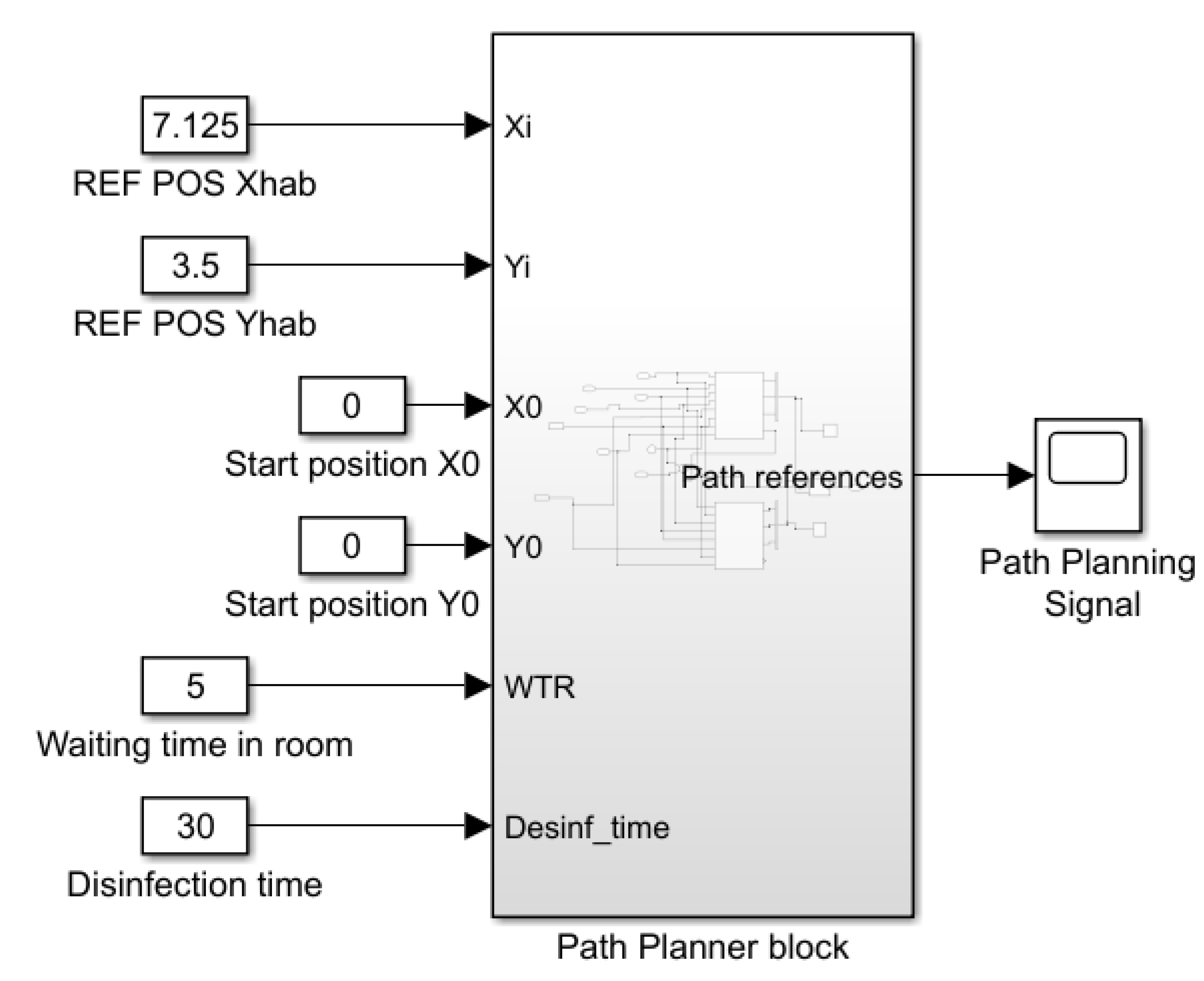
In this design, the disinfection process is set to 30 s [13]. If the duration of the planned trajectory from the supply point to the destination point is less than the disinfection time, the duration of the trajectory is extended to assure the disinfection process is completed. The same consideration is applied for the time of the return trajectory. The trajectory planner block is shown in Figure 7.

Figure 7.
Block diagram of the trajectory planner for the planar CDPR, developed in MATLAB/Simulink.
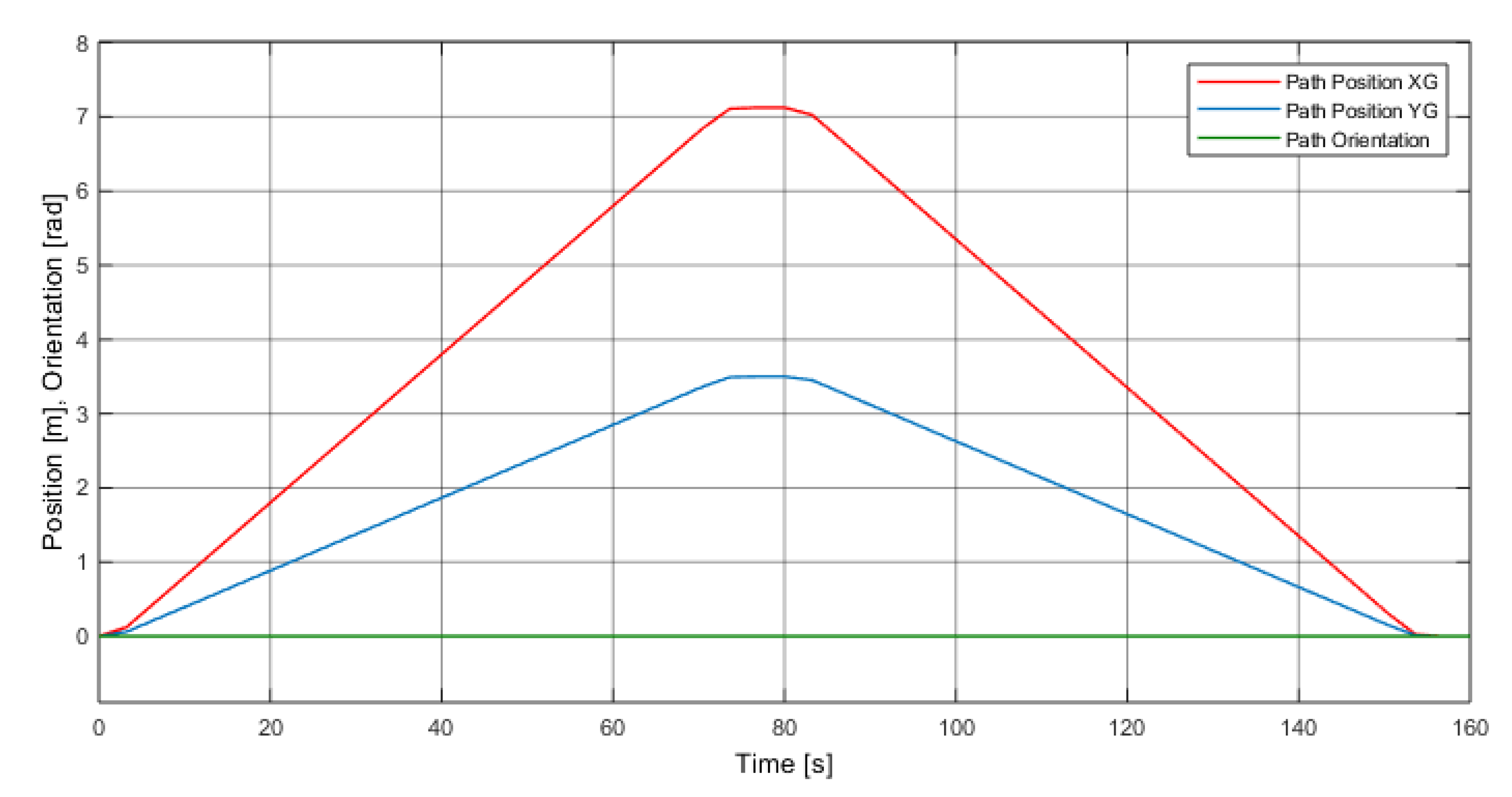
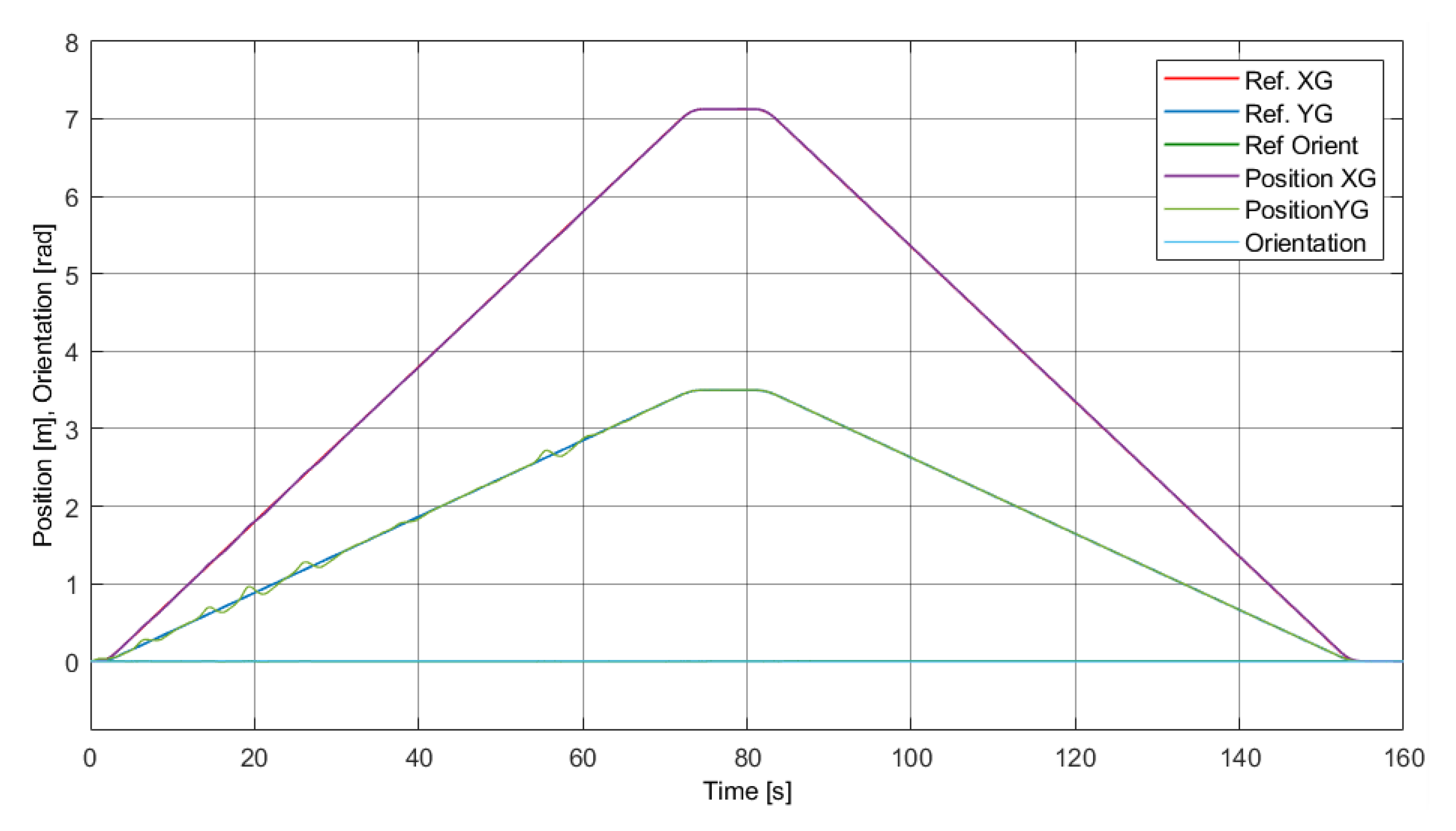
The planned trajectory in axes X and Y, along which the robot’s EE moves from the supply point towards a room, will be as shown in Figure 8, in which a minimum time of 5 s is considered to collect the supplies in the room prior to the automatic return of the EE to the supply point. This time is automatically extended while the door of the EE remains open. The initial coordinates of the trajectory correspond to the supply point [] = [0 m, 0 m] and, as an example of analysis, the coordinates of room 6 will be used, which are [] = [7.125 m, 3.5 m]. The orientation reference of the end effector is 0°, to guarantee that no rotational movements are developed, avoiding the displacement of objects inside the EE.
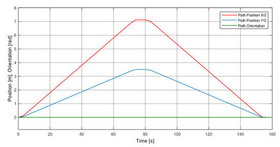
Figure 8.
Example of planned trajectories for the and positions of the center of mass and for the orientation of the EE of the planar CDPR.
2.4. Structure of the Disinfection System
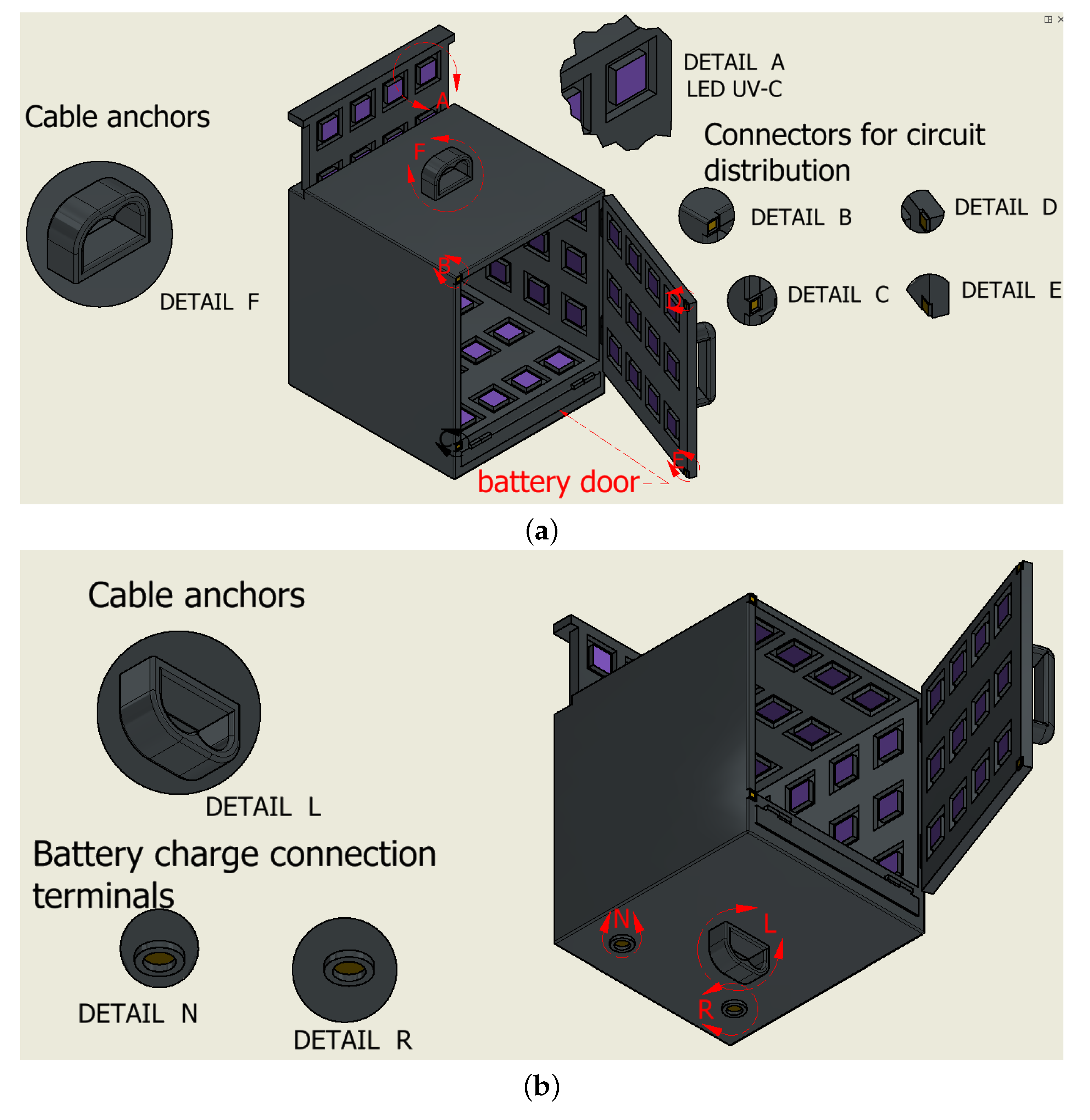
For the design of the robot’s EE, typical dimensions were taken into account for the supplies to be transported for a person in isolation, such as clothing, medicines, food, personal hygiene products, etc. Figure 9a shows the cubic design of the EE, where each edge measures 60 cm. A disinfection system has been included using UV LEDs arranged on the internal walls of the EE, as shown in the detail A of Figure 9a. There are many models of UV LEDs from different manufacturers with relatively low costs. For example, the CS63CUV365C from ChromeLED is a UV LED in a 0603 surface mount package with a 150-degree viewing angle. With 72 units of this LED covering the whole inside surface of the EE, a total power of 8 W is required when all LEDs are on. As mentioned in the previous section, the light exposure time will be at least 30 s. To power the LED system, a battery is incorporated into the lower part of the EE, which will be recharged when the robot is at the supply point. For this, a pair of terminals are included in the lower part of the EE, which are shown in detail in Figure 9b.
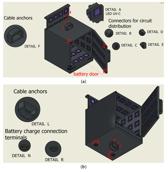
Figure 9.
Top and bottom views for the end effector. (a) Proposed design for the end effector. (b) Detail of the design of the battery recharging terminals at the bottom of the end effector.
Regarding cable anchor points, the use of duplicate cables is proposed to improve stability against movements transversal to the work plane [8]. This aspect of the design is shown in details F and G of Figure 9a for the case of the anchor points of the upper cables, and in details L and M of Figure 9b for the case of the lower cables. In this way, the upper cables are mainly responsible for the proper positioning of the EE, while the lower cables fulfill the function of keeping the EE without rotation, improving its stability [24].
3. Results
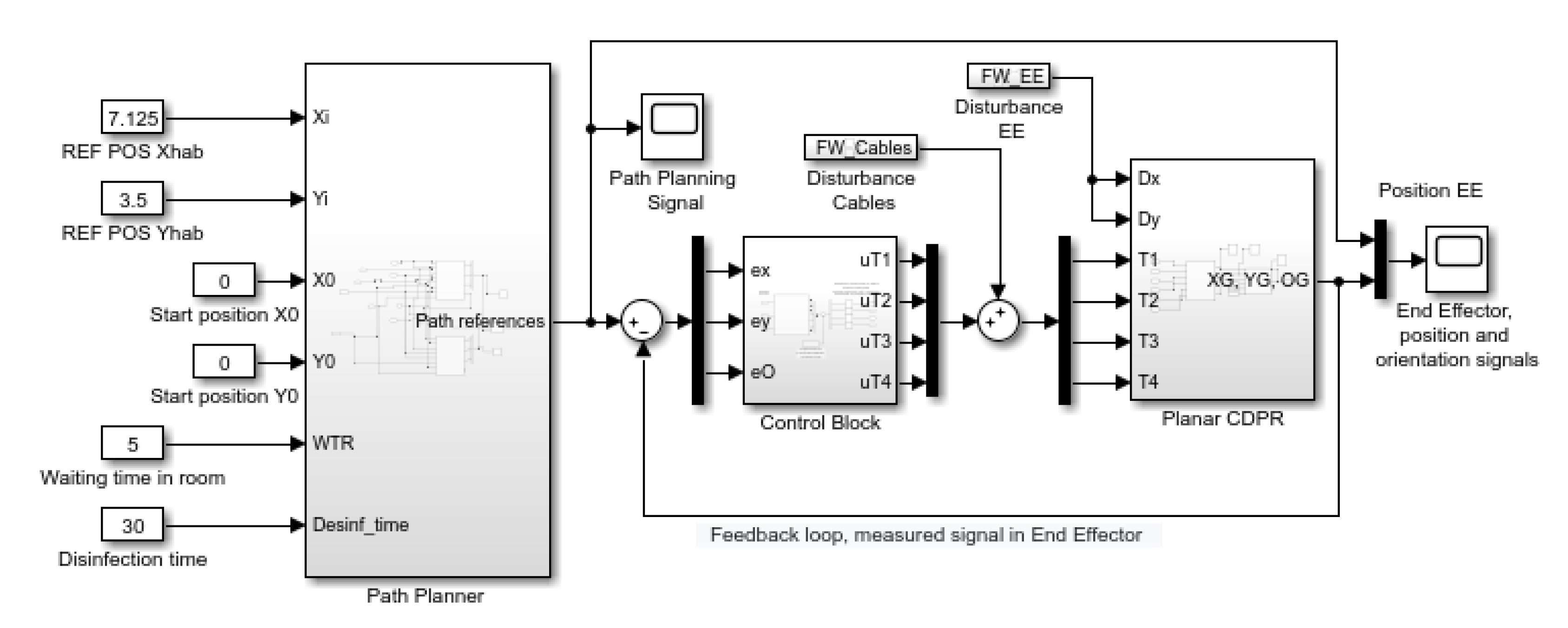
The implementation in MATLAB/Simulink of the proposed control system allows evaluating the robot movements and integrates the stages of: trajectory planning, position control stage and the dynamic model of the planar CDPR. The general block diagram of the implementation is shown in Figure 10.
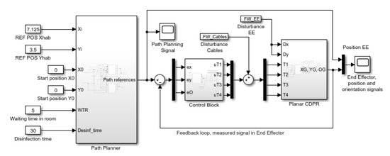
Figure 10.
Integrated trajectory planning, control system and dynamic model for the planar CDPR, developed in MATLAB/Simulink.
General Process of Operation of the Robot during the Transport of Supplies
To control the robot, it is necessary to have predefined the paths that it must follow, for which, based on the polynomial structure 6-1-6, the following parameters are assigned to the planning block:
- Starting point of the route: corresponds to the coordinates of the supply point where the EE receives the load to be transported.
- Destination point: refers to the position of the room where the transported supplies will be delivered.
- Disinfection time: corresponds to the time in which the disinfection system must act; this time is included within the movement time of the robot, being able to affect its movement speed to guarantee the required time of exposure to UV-C light.
- Waiting time in room: allows supplies to be collected and/or deposited by the user within the EE.
After a delivery or reception in the room, the trajectory planner allows developing the automatic return route of the robot to the supply point. Figure 8 shows the planned path for the robot’s movement from a supply point to a destination point and its return to the supply point.
The motion control scheme of each axis using a decoupled structure is shown in Figure 11. According to [19], the controllers can be classic PIDs or Fuzzy-PID controllers. For this case, and aware of the high non-linearities of the system, the use of Fuzzy-PID controllers is proposed since their ease of tuning and the fact that it is not required to know the mathematical model of the plant. For its tuning, the technique reported in [19] is used.
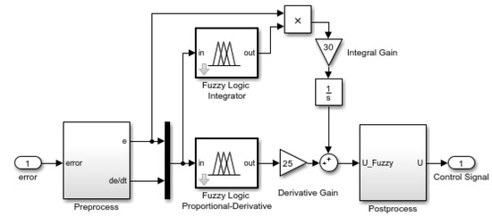
Figure 11.
Motion control scheme for each axis using a decoupled structure [19].
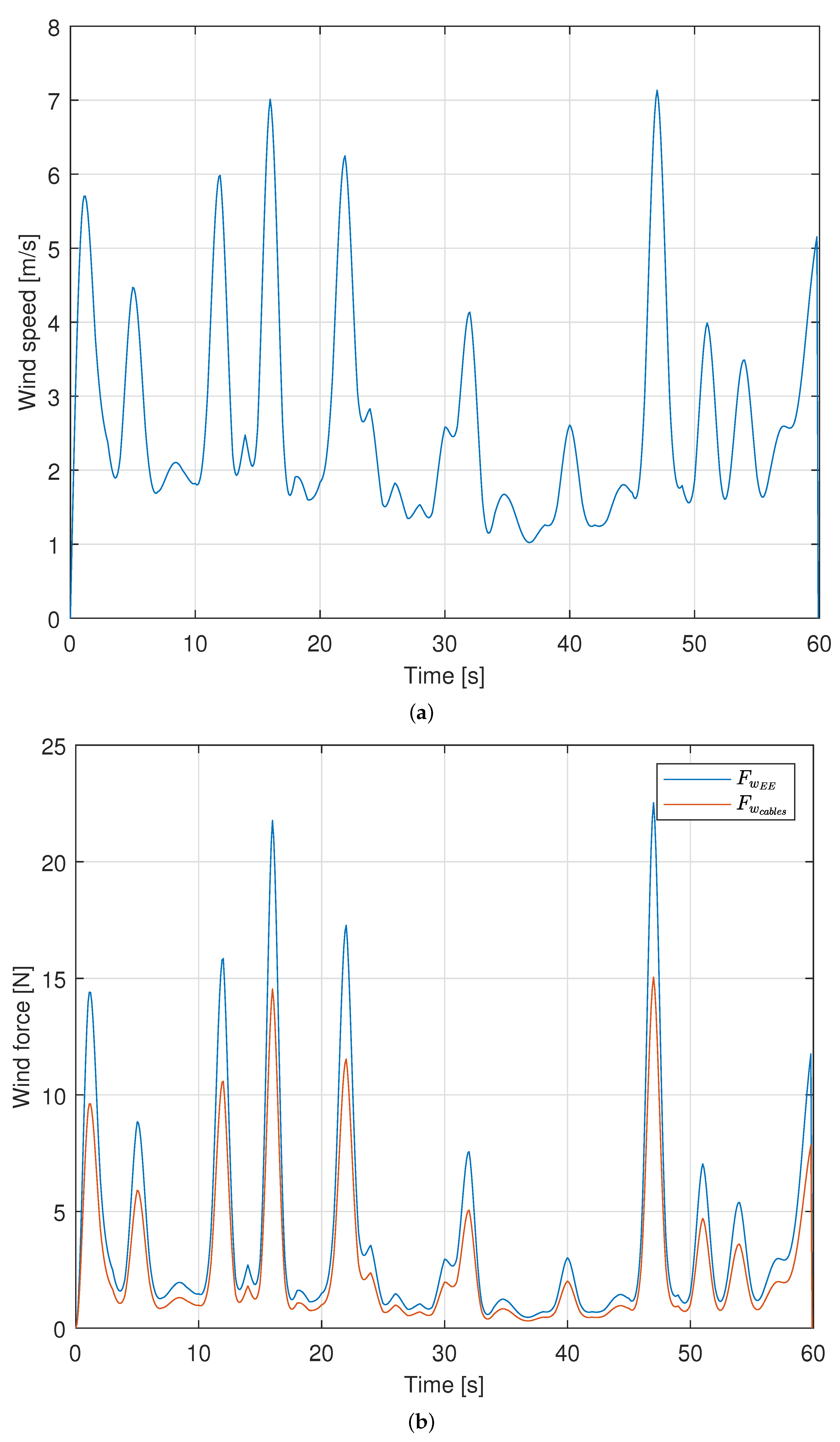
Considering that the robot operates outdoors, disturbing effects on the position of the EE, mainly due to wind, are considered. There are many approaches to obtain wind models, such as deterministic, stochastic and hybrid, presenting each of them advantages and drawbacks depending on the specific application. In this study, the wind model proposed in [25] is used, which implements a general stochastic synthesis of geophysical processes that enable a good approximation to almost any type of dependence and marginal distribution function of real process. For the example of wind speed, the authors check the validity of the model against real data of wind speed obtained from a database of Johns Hopkins University (www.me.jhu.edu/meneveau/datasets/datamap.html, accessed on 23 July 2021). The complete derivation of the model is omitted here for the sake of simplicity, but the details can be obtained in Section 4.3 of [25]. To obtain the output data of wind, the model requires five input parameters: mean (), standard deviation (), skewness (), kurtosis () and a Hurst parameter (H) required in the Hurst–Kolomogorov process used in the proposed model. From experimental measures of wind speed, the following values are set: m/s, m/s, and . For the Hurst parameter, a value of is used, as suggested by the authors of [25]. The model is set to obtain the equivalent of 60 s of wind speed data, and the resulting profile is shown in Figure 12a.
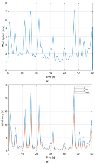
Figure 12.
Wind speed profile and resulting forces applied as a disturbance to the planar CDPR. (a) Wind speed profile obtained from the stochastic model. (b) Resulting forces due to wind.
From this profile, the forces exerted by the wind on the cables and the EE can be obtained as:
where is the density of the air (1.2 kg/m for air at normal temperature and pressure); is the frontal area of the CDPR; and is the drag coefficient, which depends on the geometry of the EE, diameter and longitude of the cables, Reynolds number, among others parameters. If a wind speed direction normal to the plane is assumed, the drag coefficient for the EE can be obtained from [26], approximating the geometry of the EE as a cube, resulting in . The frontal area for the EE considering sides of 0.6 m results in m. For the cables, a cylindrical shape can be used as a good approximation, and for the calculation of the front area, the diameter and longitude of the cable is required. Considering the structure of the hospital building used as an example in this work and supposing the CDPR in the coordinates origin, the combined exposed longitude of the cables will be 112 m. This longitude will vary for other positions of the CDPR; for example, if the CDPR is in the center of the working area (approximately in between of rooms 25 and 32), the combined exposed longitude will be 100 m. For the CDPR operating in the corners of the working area (for example room 50), the combined exposed longitude will be 120 m. If a mean value of 112 m is used for the longitude and a diameter of 4 mm is considered, the frontal area results in m. The drag coefficient can be obtained again from [26], resulting in . Applying Equation (8), the expressions relating wind speed and exerted forces in the EE and in the cables result in:
Using the profile of wind speed shown in Figure 12a, the forces acting on the CDPR are calculated and shown in Figure 12b.
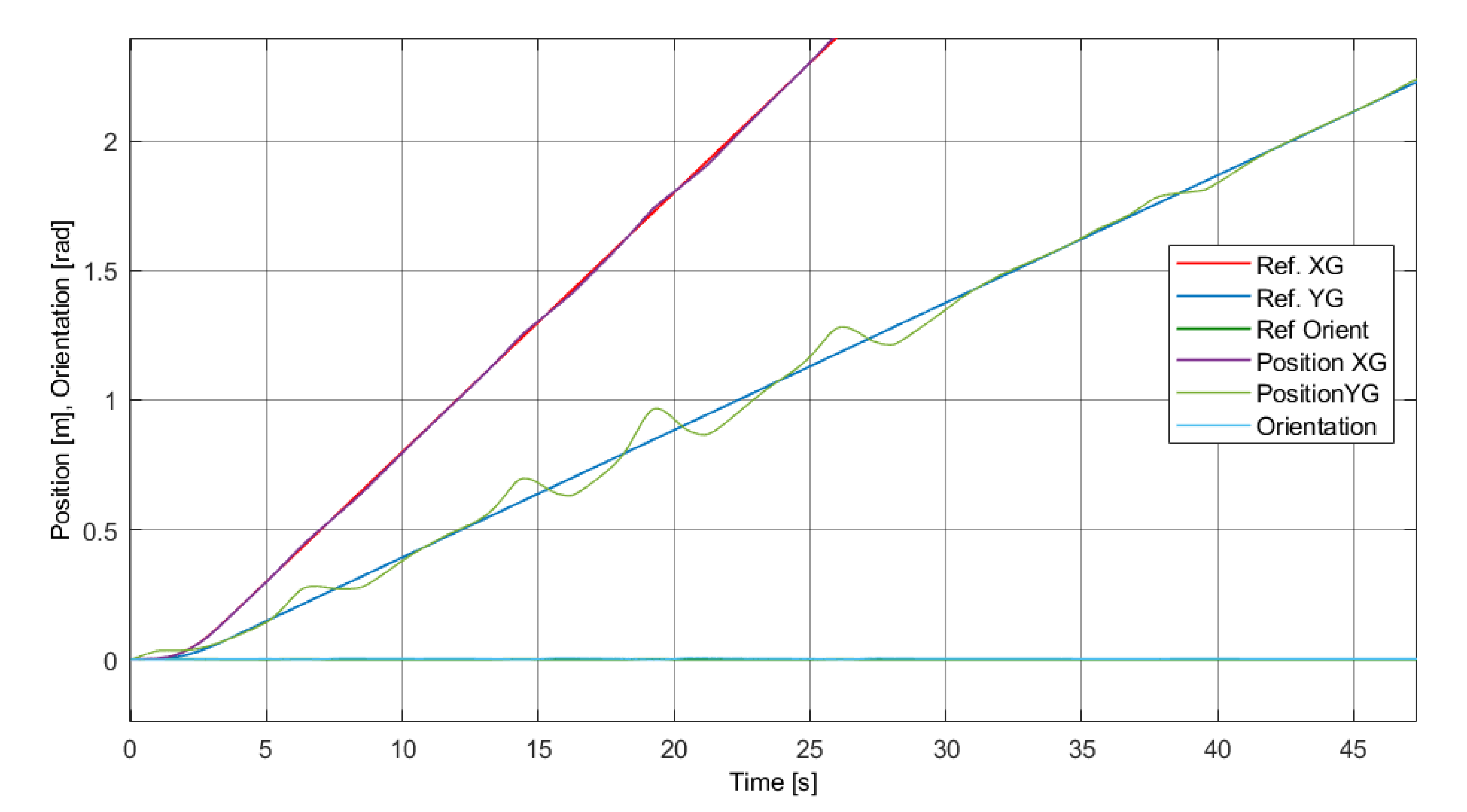
These forces are applied as disturbance to the model of the planar CDPR shown in Figure 4 and the simulated result for this example case is shown in Figure 13.
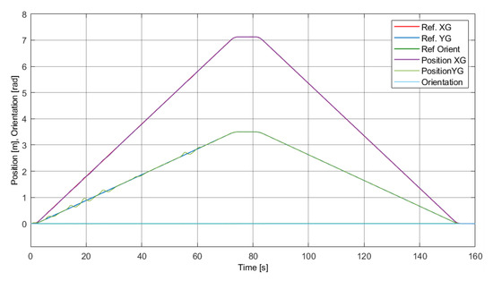
Figure 13.
Response of the robot for the task of transporting to a room and its return to the point of supply.
Additionally, the following parameters have been set to test the system:
- Starting point of the route: [] = [0 m, 0 m], which is set in the bottom center of the facade.
- Destination point: [] = [7.125 m, 3.5 m] considering room 6 as an example.
- Disinfection time: 30 s based on [13].
- Waiting time in room: 5 s.
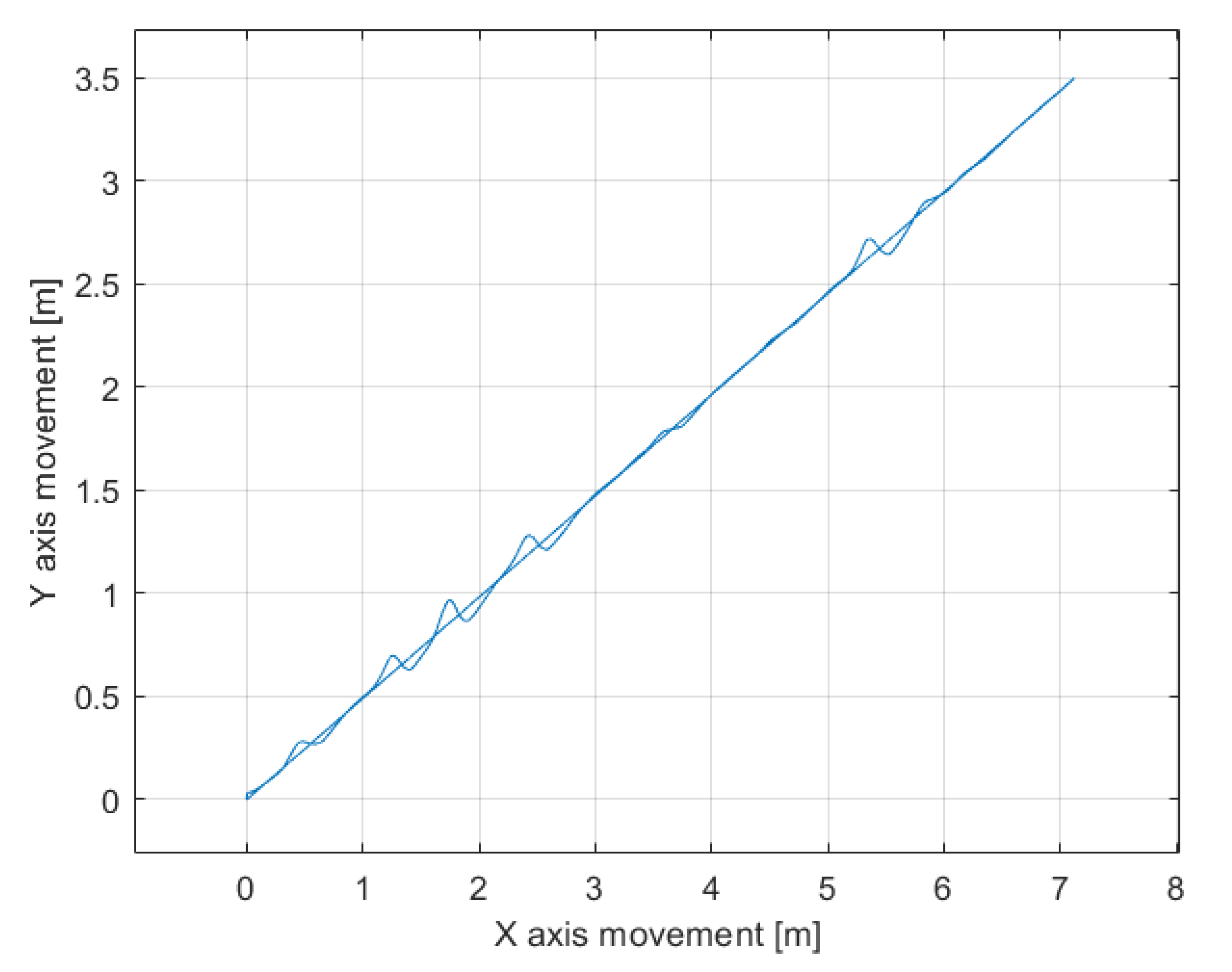
It can be seen that the positions of and closely track the planned reference trajectories imposed by the trajectory planner block, and the controller performance shows a rejection of the applied disturbances. The same response shown in Figure 13 is also depicted in Figure 14 but represented in an plane.
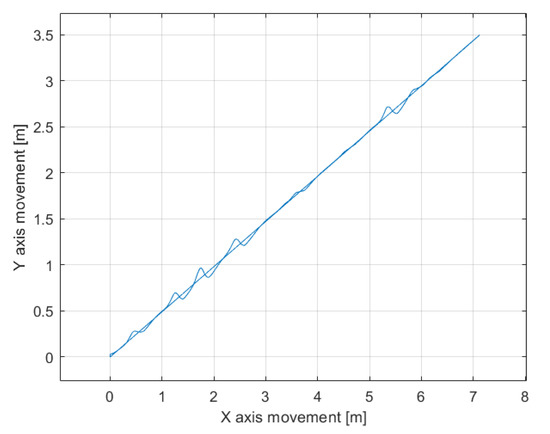
Figure 14.
The same response shown in Figure 13 represented in an plane.
4. Discussion
In Figure 13, it can be seen that the movement from the supply point to the robot’s destination point allows the time set for disinfection to be covered. After reaching the target position, the robot is parked for a minimum time of 5 s. As previously described, as long as the door to the EE is open, the robot will remain in the room. The return path of the robot also makes it possible to complete the disinfection process, taking into account that after an interaction with the user of the room, a new disinfection of the supplies that are sent to the supply point is necessary. Figure 15 zooms in on the tracking responses shown in Figure 13. At the beginning of the trajectory, a greater tracking error is observed in the variable, which is due to the action of gravity. For the same reason, the disturbance mostly affects the trajectory in the direction of the Y axis. The error has a maximum value of approximately 0.15 m, although when considering the dimensions of the total working area of the CDPR, it can be considered a minor effect.
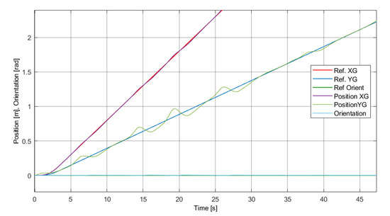
Figure 15.
Detailed view of the initial phase of the robot’s response for the task of transporting to a room.
5. Conclusions
This research work proposes a transportation alternative for health treatment facilities that helps to reduce the spread of contagious diseases, such as COVID-19. Its implementation is relatively inexpensive and fast as it requires minimal architectural intervention in buildings for the adaptation of pulley supports for the robot cables. Additionally, a wide work area can be covered, and its dimensions can be changed by redesigning the length of the robot cables.
The proposed transport of supplies includes disinfection during the robot’s movement path, eliminating the additional time required for this process when it is carried out in a traditional way by human operators. The use of the robot reduces the risk of contagion between the operators and the recipients who are in the rooms since contact or closeness between people is eliminated; at the same time, the traffic by stairs or corridors of those who transport or provide supplies is reduced or eliminated.
To summarize, the major contributions of this paper are: a novel application of a planar CDPR for transporting supplies in hospital buildings; the disinfection of the supplies carried inside the end effector by using ultraviolet light; the programming of trajectories in such a way that the time it takes to go through them is enough for the disinfection process and so that the end effector does not rotate, thus maintaining the object’s stability; the test of control loops on a dynamic model of the whole system, which includes: the mass of cables, end effector, supplies and lengths of cables for a target facade of 40 m wide and 30 m high; and the rejection of disturbances caused by wind gusts on the cables and the end effector.
This work will be complemented by other investigations currently in progress, which will cover in greater detail aspects related to the parking of the end effector, the design of the battery recharging terminals, the anchors and the number of cables, among other topics. Furthermore, future works will include the modeling of more weather effects and the corresponding control action response.
Author Contributions
Conceptualization, M.C. and R.S.; Methodology, M.C., R.S. and C.G.; Investigation, M.C., J.G. and J.V.; Software, R.S., C.G. and M.C.; Writing—Review and Editing, M.C., C.C., J.G., J.C. and J.V. All authors have read and agreed to the published version of the manuscript.
Funding
This research was supported by: The Spanish Government Projects under Grant DPI2014-57220-C2-1-P, Grant PGC2018-095939-B-I00, in part by the “RoboCity2030 DIH-CM Madrid Robotics Digital Innovation Hub, S2018/NMT-4331” and funded by the “Programas Actividades I+D en la Comunidad de Madrid”, in part by Structural Funds of the EU and the GIIRA research group at Universidad Politécnica Salesiana, Ecuador.
Acknowledgments
The authors want to thank to the health specialists for the valuable contributions to this research: María Angélica Orellana González, Pneumology Specialist, Head of the Pneumology Unit and responsible of the COVID-19 area, 6th floor of the Hospital de Especialidades José Carrasco Arteaga, IESS. Cuenca, Ecuador. Diego Xavier Carpio López, General Practitioner, Resident Physician of the Infectology COVID-19 Area at the Hospital de Especialidades José Carrasco Arteaga, IESS. Cuenca, Ecuador.
Conflicts of Interest
The authors declare no conflict of interest. The funders had no role in the design of the study; in the collection, analyses, or interpretation of data; in the writing of the manuscript, or in the decision to publish the results.
References
- Pani, A.; Mishra, S.; Golias, M.; Figliozzi, M. Evaluating public acceptance of autonomous delivery robots during COVID-19 pandemic. Transp. Res. Part Transp. Environ. 2020, 89, 102600. [Google Scholar] [CrossRef]
- Abrar, M.M.; Islam, R.; Shanto, M.A.H. An Autonomous Delivery Robot to Prevent the Spread of Coronavirus in Product Delivery System. In Proceedings of the 2020 11th IEEE Annual Ubiquitous Computing, Electronics and Mobile Communication Conference, UEMCON 2020, New York, NY, USA, 28–31 October 2020; Institute of Electrical and Electronics Engineers Inc.: Piscataway, NJ, USA, 2020; pp. 0461–0466. [Google Scholar] [CrossRef]
- Sathyamoorthy, A.J.; Patel, U.; Savle, Y.A.; Paul, M.; Manocha, D. COVID-Robot: Monitoring Social Distancing Constraints in Crowded Scenarios. arXiv 2020, arXiv:2008.06585. [Google Scholar]
- Kim, M.C.; Kim, E.S.; Park, J.O.; Choi, E.; Kim, C.S. Robotic Localization Based on Planar Cable Robot and Hall Sensor Array Applied to Magnetic Capsule Endoscope. Sensors 2020, 20, 5728. [Google Scholar] [CrossRef] [PubMed]
- Abbasnejad, G.; Yoon, J.; Lee, H. Optimum kinematic design of a planar cable-driven parallel robot with wrench-closure gait trajectory. Mech. Mach. Theory 2016, 99, 1–18. [Google Scholar] [CrossRef]
- Jin, X.; Jun, D.I.; Jin, X.; Seon, J.; Pott, A.; Park, S.; Park, J.O.; Ko, S.Y. Upper limb rehabilitation using a planar cable-driven parallel robot with various rehabilitation strategies. In Mechanisms and Machine Science; Kluwer Academic Publishers: Dordrecht, The Netherlands, 2015; Volume 32, pp. 307–321. [Google Scholar] [CrossRef]
- Elia, L.; Alonso, R.; Cañada, J. HEPHAESTUS—Highly Automated Physical Achievements and Performances Using Cable Robots Unique Systems. Proceedings 2018, 2, 558. [Google Scholar] [CrossRef] [Green Version]
- Bruckmann, T.; Lalo, W.; Nguyen, K.; Salah, B. Development of a storage retrieval machine for high racks using a wire robot. In Proceedings of the ASME Design Engineering Technical Conference; American Society of Mechanical Engineers Digital Collection: New York, NY, USA, 2012; Volume 4, pp. 771–780. [Google Scholar] [CrossRef]
- Alias, C.; Nikolaev, I.; Magallanes, E.G.C.; Noche, B. An Overview of Warehousing Applications based on Cable Robot Technology in Logistics. In Proceedings of the 2018 IEEE International Conference on Service Operations and Logistics, and Informatics, SOLI 2018, Singapore, 31 July–2 August 2018; Institute of Electrical and Electronics Engineers Inc.: Piscataway, NJ, USA, 2018; pp. 232–239. [Google Scholar] [CrossRef]
- Nishi, T.; Ando, M.; Konishi, M.; Imai, J. A Distributed Route Planning Method for Multiple Mobile Robots Using Lagrangian Decomposition Technique. In Proceedings of the IEEE International Conference on Robotics and Automation, Taipei, Taiwan, 14–19 September 2003; Volume 3, pp. 3855–3861. [Google Scholar] [CrossRef]
- Xin, J.; Meng, C.; Schulte, F.; Peng, J.; Liu, Y.; Negenborn, R.R. A Time-Space Network Model for Collision-Free Routing of Planar Motions in a Multirobot Station. IEEE Trans. Ind. Inform. 2020, 16, 6413–6422. [Google Scholar] [CrossRef]
- Barroso, A.R.; Saltaren, R.; Portilla, G.; Cely, J.S.; Carpio, M. Smooth Path Planner for Dynamic Simulators Based on Cable-Driven Parallel Robots. In Proceedings of the International Conference on Smart Systems and Technologies 2018, SST 2018, Osijek, Croatia, 10–12 October 2018; Institute of Electrical and Electronics Engineers Inc.: Piscataway, NJ, USA, 2018; pp. 145–150. [Google Scholar] [CrossRef]
- Malhotra, S.; Wlodarczyk, J.; Kuo, C.; Ngo, C.; Glucoft, M.; Sumulong, I.; Smit, M.A.; Bender, J.M. Shining a light on the pathogenicity of health care providers’ mobile phones: Use of a novel ultraviolet-C wave disinfection device. Am. J. Infect. Control 2020, 48, 1370–1374. [Google Scholar] [CrossRef] [PubMed]
- Santhosh, R.; Yadav, S. Low Cost Multipurpose UV-C Sterilizer Box for Protection Against COVID’19. In Proceedings of the 2021 International Conference on Artificial Intelligence and Smart Systems (ICAIS), Coimbatore, India, 25–27 March 2021; pp. 1495–1498. [Google Scholar] [CrossRef]
- Nerandzic, M.M.; Thota, P.; Sankar C, T.; Jencson, A.; Cadnum, J.L.; Ray, A.J.; Salata, R.A.; Watkins, R.R.; Donskey, C.J. Evaluation of a pulsed xenon ultraviolet disinfection system for reduction of healthcare-associated pathogens in hospital rooms. Infect. Control Hosp. Epidemiol. 2015, 36, 192–197. [Google Scholar] [CrossRef] [PubMed] [Green Version]
- El Majid, B.; Motahhir, S.; El Hammoumi, A.; Lebbadi, A.; El Ghzizal, A. Preliminary Design of a Smart Wristband Disinfectant to Help in Covid-19 Fight. Inventions 2020, 5, 32. [Google Scholar] [CrossRef]
- Guerrero-Beltran, J.A.; Barbosa-Canovas, G.V. Advantages and Limitations on Processing Foods by UV Light. Food Sci. Technol. Int. 2004, 10, 137–147. [Google Scholar] [CrossRef]
- Taghirad, H. Parallel Robots: Mechanics and Control, 1st ed.; CRC Press: Boca Raton, FL, USA, 2013. [Google Scholar]
- Carpio, M.; Saltaren, R.; Viola, J.; Calderon, C.; Guerra, J. Proposal of a Decoupled Structure of Fuzzy-PID Controllers Applied to the Position Control in a Planar CDPR. Electronics 2021, 10, 745. [Google Scholar] [CrossRef]
- Kaur, A.; Kaur, A. Comparison of Mamdani-Type and Sugeno-Type Fuzzy Inference Systems for Air Conditioning System. Int. J. Soft Comput. Eng. IJSCE 2012, 2, 323–325. [Google Scholar]
- Carpio-Alemán, M.; Orozco-Tupacyupanqui, W.; Betancur-Betancur, M. Design and simulation of a fuzzy controller for Vertical Take off and Landing (VTOL) systems. In Proceedings of the 2016 IEEE International Autumn Meeting on Power, Electronics and Computing, ROPEC 2016, Zihuatanejo, Mexico, 9–11 November 2016; Institute of Electrical and Electronics Engineers Inc.: Piscataway, NJ, USA, 2017; pp. 1–6. [Google Scholar] [CrossRef]
- Ponce, P. Inteligencia Artificial Con Aplicaciones a la Ingeniería, 1st ed.; Alfaomega: Mexico City, Mexico, 2010; pp. 1–376. [Google Scholar]
- Merlet, J. Parallel Robots, 2nd ed.; Springer: Berlin/Heidelberg, Germany, 2006; p. 402. [Google Scholar]
- Carpio Alemán, M.; Saltaren, R.; Rodriguez, A.; Portilla, G.; Placencia, J. Rotational Workspace Expansion of a Planar CDPR with a Circular End-Effector Mechanism Allowing Passive Reconfiguration. Robotics 2019, 8, 57. [Google Scholar] [CrossRef] [Green Version]
- Dimitriadis, P.; Koutsoyiannis, D. Stochastic synthesis approximating any process dependence and distribution. Stoch. Environ. Res. Risk Assess. 2018, 32, 1493–1515. [Google Scholar] [CrossRef]
- Kelbaliyev, G.I. Drag coefficients of variously shaped solid particles, drops, and bubbles. Theor. Found. Chem. Eng. 2011, 45, 248–266. [Google Scholar] [CrossRef]


Publisher’s Note: MDPI stays neutral with regard to jurisdictional claims in published maps and institutional affiliations. |
© 2021 by the authors. Licensee MDPI, Basel, Switzerland. This article is an open access article distributed under the terms and conditions of the Creative Commons Attribution (CC BY) license (https://creativecommons.org/licenses/by/4.0/).