Article

Simulating Ionising Radiation in Gazebo for Robotic Nuclear Inspection Challenges

1
Department of Electrical and Electronic Engineering, University of Manchester, Manchester M13 9PL, UK
2
Department of Engineering, Lancaster University, Lancaster LA1 4YW, UK
3
Oxford Robotics Institute, University of Oxford, Oxford OX2 6NN, UK
*
Author to whom correspondence should be addressed.
Robotics 2021, 10(3), 86; https://doi.org/10.3390/robotics10030086
Submission received: 31 May 2021 / Revised: 29 June 2021 / Accepted: 2 July 2021 / Published: 7 July 2021
(This article belongs to the Special Issue Advances in Robots for Hazardous Environments in the UK)

Abstract

:
The utilisation of robots in hazardous nuclear environments has potential to reduce risk to humans. However, historical use has been largely limited to specific missions rather than broader industry-wide adoption. Testing and verification of robotics in realistic scenarios is key to gaining stakeholder confidence but hindered by limited access to facilities that contain radioactive materials. Simulations offer an alternative to testing with actual radioactive sources, provided they can readily describe the behaviour of robotic systems and ionising radiation within the same environment. This work presents a quick and easy way to generate simulated but realistic deployment scenarios and environments which include ionising radiation, developed to work within the popular robot operating system compatible Gazebo physics simulator. Generated environments can be evolved over time, randomly or user-defined, to simulate the effects of degradation, corrosion or to alter features of certain objects. Interaction of gamma radiation sources within the environment, as well as the response of simulated detectors attached to mobile robots, is verified against the MCNP6 Monte Carlo radiation transport code. The benefits these tools provide are highlighted by inclusion of three real-world nuclear sector environments, providing the robotics community with opportunities to assess the capabilities of robotic systems and autonomous functionalities.

Graphical Abstract

1. Introduction

The use of robotics to remove humans from hazardous environments has been increasing in recent years [1]. In particular, robotic solutions have been used to decrease the risk to radiation workers during routine and emergency scenarios in the nuclear sector [2]. Robots can be designed to monitor ambient radiation levels and identify contamination [3,4,5], monitor spent fuel and assets [4,6] and handle materials [7,8], amongst other general inspection tasks, whilst monitoring their own internal radiation exposure to avoid damage to circuitry and materials [9].
The use of robots has been highlighted as a key area for development for nuclear decommissioning and monitoring efforts in the United Kingdom [4] as well as globally [2], with the possibility to not only protect human health, but to reduce cost, accelerate operations, and improve repeatability and information collection capabilities through in situ sampling and inspection. However, robotic solutions need to demonstrate safe and reliable operation in a number of scenarios before their adoption will be widespread. Without this, stakeholder confidence in the use of autonomous robots will be low, resulting in limited uptake of such systems. Recently, the UK nuclear industry suggested that software validation and verification, along side specific trials, will be a necessary part of testing robotic systems before deployment into the most harsh environments [10].
One solution is to use representative facilities [2,11,12,13]. These allow for testing of a robot’s capabilities in a realistic demonstration site, without the presence of certain hazards. However, by lacking these critical hazardous components, there will be a fundamental impact on the autonomous behaviour of a robotic system, which can raise concerns over insufficient testing. It is imperative that algorithms and autonomous elements of these systems are exposed to situations where radiological or other hazardous materials are present to force the testing of reactionary behaviours.
Gaining access to active sites for continuous testing of systems can be difficult, typically due to security, radiation exposure, and contamination concerns. Moreover, minimising radiation exposure in accordance with the principals of ALARP (As Low As Reasonably Practicable) can greatly limit the strength of radioactive sources used in laboratory trials and testing. Though these scenarios have utility, they are ultimately unrepresentative of the most challenging radiation environments faced by robots, which can contain large quantities of mixed and dispersed radioactive materials [14].
To reduce the need for excessive deployments into active scenarios during routine development of robotic systems and to reduce lead times and operator exposure in accordance with ALARP, a method to test robotic capabilities within a simulated radiation field is required. Furthermore, there exists a growing requirement for robots, particularly whilst under development, to have compatibility with the Robot Operating System (ROS), including at a regulatory or governmental level [15]. As a result, an increasing number of bespoke and Commercial-Off-The-Shelf (COTS) platforms and radiation sensing instruments are being made ROS compatible [3,5,16,17,18,19]. Currently no existing codified solution to simulate complex radiation fields and sensors in a ROS compatible manner is available to researchers and industrial operators, greatly inhibiting development of nuclear-relevant robots.
Simulation tools have been a useful resource for the robotics community for many years, removing the need for access to sites or physical robots. These simulation environments provide safe scenarios in which to test robots and algorithms, whilst removing many of the previously highlighted issues regarding site access, variety and safety. One popular simulation environment used in the robotics community is Gazebo [20], offering physics based simulations of robot mechanisms and sensors with extensive ROS integration. This allows for control of simulated robots in the same way real systems would be used with ROS, with the ability to run the same code on both. These simulation tools are useful, but can be challenging to set up and to edit. For tasks such as environmental monitoring, they can often be difficult to extend with additional functionality.
This work addresses this pressing need by providing a simulation based approach for extensive testing of robotics in nuclear environments. It presents the use of the natively ROS-compatible physics simulator Gazebo [20] with a custom radiation sensor plugin implemented to mimic the behaviour of radioactive sources and sensors. This allows for an environment in which developers can continue to leverage the existing functionality of Gazebo to model robots, their sensors (such as LiDAR and cameras) and their interactions with physical environments, whilst providing the additional capability to simulate radiation fields. Simulated radiation sensors can publish information directly to ROS, enabling rapid development of algorithms and autonomous behaviours pertaining to radiation with the rest of the robot’s general functionality. Simulations have been identified as a key resource for predicting, planning, verification, and validation of research [21], and this work allows developers to exploit simulated environments more effectively for nuclear-centric robotics.
Tools are also provided and demonstrated to quickly build and prepare simulated environments that contain items that would commonly be found in facilities requiring inspection in nuclear scenarios, such as storage drums with differing structural conditions (deformation, swelling, corrosion etc.). Multiple radiation sources of varying locations and magnitudes can be easily generated along with multiple radiation detectors of defined sensitivity response.
The article will present how these tools can be used to generate complex and unique environments before presenting an example of realistic radiation mapping of an environment, through the use of the radiation plugin integration, which previously has not been possible. Using the radiation plugin with the world building tools presented gives the users the ability to develop algorithms which try to reduce/limit total dose received by a robot by avoiding high dose areas, without having to access such a facility. The environments developed interact with the radiation to shield and attenuate the radiation measured by the robot.
Currently, there exist several challenges issued by organisations to promote remote inspection of nuclear environments. These challenges contain many of the generic difficulties faced by industry and include the IAEA (International Atomic Energy Agency) Robotics Challenge [22], the European Robotics Hackathon ENRICH [23], Sellafield Ltd Game Changers challenges [24] and the Fukushima Robot Test Field [25]. In this same manner, this work provides prearranged test environments in which users can benchmark robot platforms, closely referenced to real-world deployment opportunities, based on facilities in the UK such as Sellafield and Culham Centre for Fusion Energy (CCFE). In each environment, activities have been suggested based on the needs of UK nuclear stakeholders. These are centred around key activities which rely on sensors reporting on radiation, radiation mapping, source identification, and monitoring of robot health.
The article is structured as follows: Section 2 details the usage of the world builder tools and the Gazebo implementation for the radiation sensor plugin and its underlying physics approach. Demonstration and benchmarking of the radiation simulation is reported in Section 3, followed by a discussion of the limitations and challenge scenarios in Section 4. Final concluding remarks are found in Section 5.

2. Materials and Methods
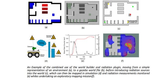
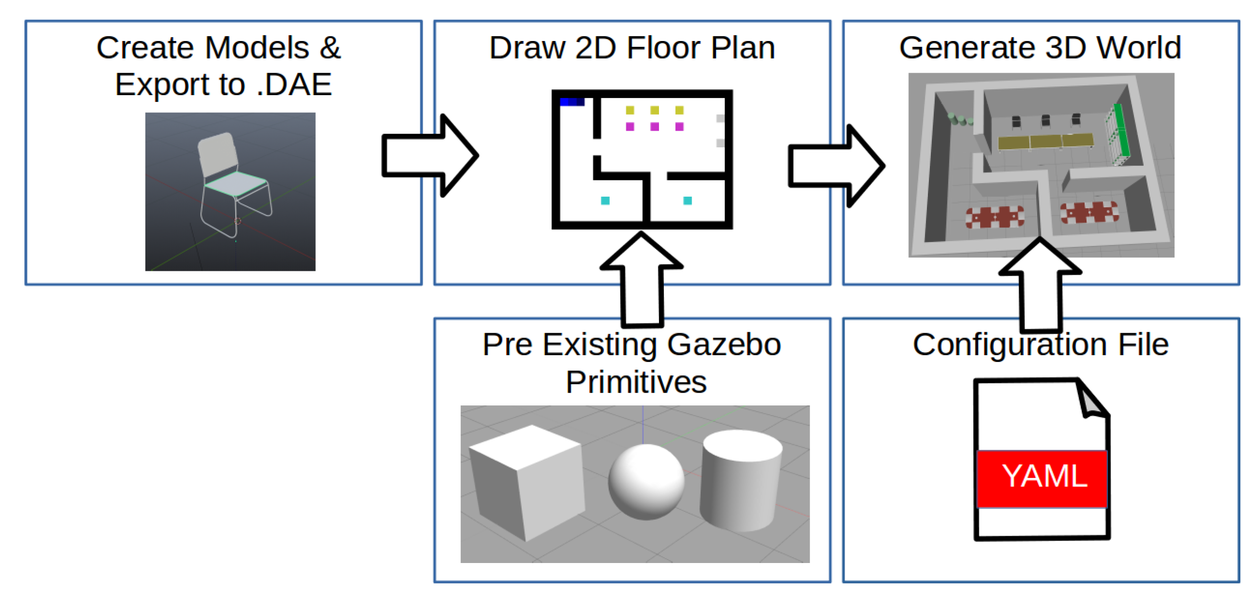
2.1. World Building

The main motivation for providing world builder tools is to give typical users the ability to test in a variety of realistic environments, when access to hazardous scenarios is restricted. For the nuclear example, the International Atomic Energy Authority classifies radioactive material into several levels of severity, with all but the lowest level being deemed as controlled substances [26,27]. This makes accessing these materials for testing and the facilities which house them difficult. The only materials which are allowed to be released are of very low levels of activity and often only released for scientific research, making access to realistic hazards extremely scarce. This may also be the case for biological or chemical substances which pose a threat to human health. These limitations impose barriers when trying to design and test monitoring algorithms which take such hazards into account. When testing in real-world facilities that contain hazardous substances, secondary dangers such as structural damage may be too great to allow on-site access—for example, the building damage at the Fukushima Daiiachi power station [28].
This has led many to build example environments for testing robots, with either no or analogous hazards [11,12,13,29]. These test facilities try to provide realistic scenarios for testing and rehearsals of robot missions without the possibility of severe consequences in the event of an error [30,31]. Whilst helpful, it can be hard to test scenarios exhaustively and mimic specific effects of some hazards, which could have a significant operational impact. This can make it difficult for operators and stakeholders to have confidence in algorithms designed for specific scenarios, due to the limited amount of testing.
A popular framework in the robotics community is the robot operating system (ROS). ROS is compatible with a number of simulation tools such as CoppeliaSim (formerly V-REP), Webots and its default, Gazebo [32,33,34,35]. Gazebo offers realistic physics modelling of environments, robots and their sensors. Gazebo environments are described using Simulation Description Format (SDF) files which contain attributes and relationships between objects within the world, with examples being position, colour, shape, linkage to another body, etc. These objects can be either Gazebo primitives, such as cubes, spheres, cylinders, or Colleda meshes which can be used to display arbitrarily complex models. Whilst being an invaluable tool, generating these files manually, particularly for complex environments of many elements, can be tedious and therefore limits the number of environments used for trials.
This has led to the development of tools which are able to rapidly generate environments from data such as floor plans or representative images. Lavrenov et al. [36] used robot derived occupancy grid images to produce a binary height map based on obstacles. The tools developed by Abbyasov et al. [37] allow for large environments to be generated from greyscale images. However, these environments are made of a single continuous mesh extruded from the floor, with a single texture, and only allowing variation in the height component. These existing world generation toolkits do not allow for the generation of individual models or elements in the Gazebo SDF file, rather the whole world described as a single monolithic mesh. The limitations of existing world generation toolkits can make it difficult to extend them to incorporate additional hazards or unique features, making them unsuitable for monitoring tasks, where differences between similar entities in an environment need to be detected. Furthermore, these tools are limited to static environments, and are not readily suited to allowing for evolution of environments based on time or environmental factors.
This article presents and makes available a toolbox which addresses some of these limitations, offering several key features for rapidly producing complex environments suitable for industrial inspection challenges. These environments can be made of both simple geometric models or complex meshes which are used as building blocks in the larger world using a variety of models and textures. These environments can then be altered and deformed to simulate dynamics or degradation in a structured or random way to simulate the passage of time in an environment. This implementation is then extended to work with the radiation sensor plugins, explained in Section 2.2, which allow for phenomena not included in Gazebo’s physics engines to be modelled (e.g., radiation or thermal transport). Explanations of how each of these features has been addressed are presented throughout this section.

2.1.1. Graphical Environment Builder

The work flow of how to generate an environment from a user-defined image using the tools covered in this section is shown in Figure 1, where an image and a configuration file can be used with custom or existing models to generate an environment. Some examples of user defined images and the subsequent generate Gazebo world can be seen in Figure 2. Where this tool goes beyond previous world builders is by allowing custom models to be used as building blocks in the world builder to procedurally generate an environment. This allows for significantly more complex environments to be generated in a rapid manner.
Existing models and primitives can be placed into an environment by drawing a pixel representation of the environment, where different RGB colours can be used to represent different models/variations of models. The colour can also modify the size, or how many models to stack on top of each other; this can be seen in Figure 2a, where a representative drawing has been used to generate an environment. Blue indicates cylinders, representing storage drums, and red indicates cuboid volumes representing other environmental features. Note how the drums and blocks are stacked to different heights in Figure 2d based on the shade of blue or red used.
The effect of different colours and their shades is specified in the associated configuration file. These contain information on how the image is related to the simulated world in terms of scale, centring, positional noise, colouring, along with filepaths of any custom models or textures used. This can be seen in Figure 2b, where custom drums with a higher mesh density have been introduced using the grey pixels and normal cylinder primitives with blue. In Figure 2k, a complete environment has been produced using custom coloured pixels in in Figure 2h to represent custom elements such as storage drums, chairs, desks tables and bookshelves. Figure 2i,l shows how a full CAD model of an environment can be imported using this toolkit, extending its utility beyond pictorial representations.

2.1.2. Procedural World Generation

As many elements in an environment can be copies of a single model, it can be difficult to test algorithms which rely on or aim to detect differences indicative of wear or a failure condition.
In real-world environments, there will typically be subtle or even major variations between similar objects. To include differentiation between models, a service has been developed, which allows for worlds which have multiple identical elements to be exported into a new environment, where alterations from the initial model are made, making each model instance unique. These alterations can be driven in a number of ways. An example is the addition of “salt and pepper noise” to the model, causing perfectly smooth surfaces to become rough. The workflow for generating environments with unique models is shown in Figure 3 with an example of noise added to models after export, shown in Figure 4.

2.1.3. Procedural World Evolution

Once a version of the world has been generated where each element is unique, a user can specify models and textures which can be altered through time to reflect naturally occurring processes. Using a set of configuration files it is possible to define which models are able to be deformed, have their textures altered, be moved within/removed from the environment, or any combination of the aforementioned, with each subsequent generation of the simulation. This can be applied to all models or to a subset of models selected either manually or randomly.
To allow for effective physical degradation of objects within an environment, the models used must be of a sufficiently high mesh density. Many primitive models use fewer vertices, to reduce computational overheads. Unfortunately, low polygon shapes do not respond well to the previously described augmentations of shape and texture. For effective modification, any models used should be created with a high mesh density. If a model is not of a sufficient mesh density, scripts are provided as part of this toolkit to increase the mesh density, as shown in Figure 5.
Implemented deformations are used to represent, bulging of vessels due to increased pressure, damage causing dents, and ageing of paint/corrosion of materials through discolouration, all common issues in degrading environments. These environments can be constantly iterated to provide sustained degradation over the equivalent of months or years for testing and development of robotic systems. The workflow of how to evolve an environment is shown in Figure 6 with examples of the implemented evolutions shown in Figure 7.
Evolutionary deformations can be either random or defined mathematically. For bulging, each vertices in the model is altered based on the desired axis of deformation, bulge scale factor and its distance to a defined bulge centre point. Figure 7 shows how changing the centre location within the barrel can cause different types of bulging. The example labelled uniform deformation had the centre of the model defined as its bulge centre, whilst the nonuniform deformation had its centre defined towards the upper right corner of the barrel, as displayed.
Likewise, discolouration can be achieved either through the addition of salt and pepper noise to an entire texture, weighted in the red, green, and blue channels as required to make textures nonuniform/discoloured, or texturing effects can be implemented. One implemented texturing effect is corrosion, achieved by defining the RGB limits of the colour of metal oxides and a ratio (which describes the state of corrosion) in a configuration file. A random or specified position is then selected on the texture map associated the model and a random expansion is applied until the number of “corroded” pixels is equal to the total number of pixels multiplied by the ratio. This can be repeated through iterations causing a random expansion each time. An example of corrosion and bulging applied to an evolved environment is shown in Figure 8, compared to the first iteration in Figure 2e.

2.1.4. Environmental Hazard Generation

These tools have been designed to integrate and work with nonphysical and visual effects. It is possible to attach environmental elements to any model within the world through the use of gazebo plugins and a configuration file. For demonstrative purposes, this article uses the ionising radiation plugin, developed as part of this work and described in Section 2.2; however, the same technique could be used to add elements such as realistic heat or chemical sources depending on what the simulation requires.
To support these environmental effects, some considerations need to be made when initially setting up the environment, with certain effects being driven on a per model basis. For example, attenuation of ionising radiation through objects requires knowledge of the object material, which is achieved through the model’s name, an example being containment_vessel_aluminium to specify aluminium. This allows Gazebo to identify and apply the correct attenuation factor of gamma flux passing through objects when calculating the sensed level of radiation.
An example of the integration of adding environmental elements can be seen in Figure 9, where radiation sources have been added to various elements within the environment implemented through the presented tools. A sensor was added to a mobile robot with the result of running a characterisation mission shown in Figure 9c. Here, it can be seen how objects in the environment can easily have environmental elements attached to them, with other objects interacting with these radiation sources, in this case shielding the robot from gamma flux.

2.2. Modelling Radiation

This section focuses on reproducing the spatial behaviour of gamma-ray flux intensity from point sources of radioactive decay, and considers phenomena such as the attenuation through various materials. Whilst the work can be extended to simulate other types of radiation in the future, for example, alpha and beta, at this stage the work focused on gamma radiation as it is gamma environments that present the most immediate challenge to human workers and where robotic systems offer the greatest potential. Furthermore, electronic components and robot materials are susceptible to damage from gamma radiation, and as such robots may need to actively monitor and act upon the dose rate of gamma that they receive. In contrast, although it may be necessary for a robot to actively avoid alpha and beta sources to minimise the spread of contamination, these radiation sources are typically unable to penetrate the chassis of a robot and cause damage and are therefore not considered in this work. More exotic particles, such as neutrons and those found in extraterrestrial environments, are also not considered. However, they will be necessary in the future as fusion facilities and accident scenarios may well contain neutron sources.
The majority of ground, aerial and marine robots that are deployed to undertake survey missions, for mapping, imaging and characterisation tasks, focus on gamma radiation [2,38], and therefore modelling gamma-rays has most utility to the wider research and industrial communities at this time. These robot systems may rely on autonomous behaviours that try to maximise coverage or data quality, either independently or in conjunction with robot dose monitoring. For survey tasks and to monitor robot health, radiation detectors are required to provide the robot with information regarding the radiation environment. These sensors may be mounted inside or outside the chassis of a robot depending on its purpose.
Figure 10 demonstrates some of the challenges facing robots in remote inspection tasks. Firstly, there can be multiple radioactive sources in three dimensions which influence the radiation flux experienced by the robot and its sensors. The intensity of this flux is strongly correlated to the distance from the source. Secondly, in unstructured nuclear environments, there may be existing shielding materials or objects of arbitrary shape which attenuate radiation, and this effect needs to be accounted for. Finally, robotic components and radiation detectors may be collimated or have innate sensitivity profiles based on their orientation to incoming flux; therefore, the orientation of the robot can greatly impact the measured dose or intensity of radiation.

2.2.1. Underlying Model

In this work, sources are defined by coordinates in Cartesian space and an activity value (in Becquerels) and a series of functions then define the intensity observed by a simplified simulated detector as a function of distance, d, from the origin of the source. For gamma sources, the intensity with distance is often approximated as an inverse square relationship [39], i.e., I d 1 / d 2 . To avoid numerical instabilities as d 0 , I d , a softening term ϵ can be used in quadrature with d [40], which is negligibly small for most calculations.
However, to better reflect the physical reality of a detector as it approaches a source, in this work the intensity of radiation is modelled as the flux incident on a detector of circular profile. The solid angle, Ω , subtended by this pseudo detector then provides a fraction of total fluence captured from the source. The total solid angle is given as 4 π , and therefore the fraction of total flux I at distance d is given by Equation (1).
I d = Ω 4 π = I 0 2 1 d r 2 + d 2
As d 0 , the intensity reduces to half the total source intensity, a physically more realistic result than more common inverse square distance approximations. The radius of the pseudo detector r is deliberately kept small at 1 × 10 2 m as to give users a more predictable inverse square distance approximation at larger length scales. The detector is modelled as always facing normal to all sources; therefore, Equation (1) holds regardless of position or orientation of the detector to the source.
When passing through a medium, gamma-rays are attenuated. In air this attenuation is negligible over short distances of a few meters; however, for denser materials attenuation can be significant over distances of only a few centimetres. With a nonzero attenuation coefficient, α , the intensity should be reduced upon exiting a medium in accordance to the Beer–Lambert Law (Equation (2)).
I v = I u exp ( α z )
The intensity exiting an attenuating medium I v is a function of the inbound intensity I u , and the distance travelled z in metres. The attenuation coefficient α has units m 1 , and can be defined by the user on a per material basis to provide the desired scaling of attenuation for object scale lengths in the simulated environment. Common values for linear attenuation coefficients can be calculated from NIST database of X-ray mass attenuation coefficients [41].
Real-world detectors are not uniformly sensitive to radiation with respect to orientation, mostly due to geometric factors. Furthermore, detectors may be more or less efficient with respect to other sensor designs for similar geometry. Sensors may be collimated with materials such as tungsten or lead to greatly localise sensitivity to a particular orientation relative to a point source [19,42]. The response of the detector can be modified to account for these idiosyncrasies through use of a user-specified sensitivity function. This sensitivity function η ( θ ) allows users to describe the response of detectors due to their geometry, efficiency or collimation, or can be ignored to mimic an isotropic uniform detector. The orientation of a source relative to the detector frame is given by the angle relative to the (0, 1, 0) direction in the sensor frame and users merely choose an included default profile, such as uniform or Gaussian, or define a custom function which returns a value between 0–1 as a function of said orientation.
I = i η i I 0 i 2 1 d i r 2 + d i 2 j exp ( α j z j )
Equation (3) describes the eventual detected radiation intensity as the sum of all contributions from i sources in an environment at their respective distances, d, sensor orientation sensitivity, η , source activity, I 0 and attenuation due to j objects with their respective coefficients and length of medium. How this is implemented in the Gazebo physics simulator will now be discussed.

2.2.2. Gazebo Implementation

Previous use of physics simulators and video game engines to recreate nuclear environments has largely been separated into two sub categories. There have been efforts to model radiation fields, predominantly for dosimetry training [43] and dose estimation of radiation workers, or to model robot deployment into mock nuclear facilities [44,45]. The former contains inverse square distance estimations of radiation exposure rate but not robot interaction, whereas the latter has simulated robot systems without radiation field estimations. Recently, work has been undertaken to model a Compton camera with only primitive geometries with ROS and Gazebo [46]; however, robotic systems for nuclear inspection utilise a wide variety of sensor types [47].
A priority of this implementation is to maximise its utility to robotic systems developers, whilst minimising the barrier to entry associated with learning new software. Gazebo is the default physics simulator accompanying installations of ROS, and the majority of tutorials and resources available for developers are designed with Gazebo in mind. This places Gazebo as a natural choice for a physics simulation environment to include ionising radiation.
Gazebo already offers simulation of sensors such as LiDAR, depth and RGB cameras, and the interaction between radiation sources, sensors, and environmental elements are handled using the same physics simulation capabilities. The simulator developed in this work defines individual sources of constant activity attached to a physical object, e.g., embedded in an existing asset or as a standalone primitive model. A pseudo sensor object is then loaded, which registers all the currently loaded sources in the simulation, and continues to monitor the contribution from each source during the simulation.
To calculate 3D euclidean distances between the object origins of sources and pseudo sensors, this implementation uses the native ODE (Open Dynamics Engine) physics library in Gazebo. This provides distance values for Equation (3), whilst also providing collision information for an imaginary ray between a source and a sensor object. When the imaginary ray passes through an environmental object, the object properties and entry/exit coordinates are provided to calculate the path length z through said object. The attenuation coefficient is retrieved from a lookup table which maps the material name of an object to its respective coefficient. The product of these attenuation contributions is calculated for each source.
The resolution of the line length estimation is 1 × 10 4 m, much finer than features in the environment or components such as the robot chassis thickness. However, this resolution can be increased at the cost of additional computation.
To provide modification of detector sensitivity based on orientation, the dot product between the ( 0 , 1 , 0 ) axis in the sensor frame, and the vector between the detector and a source provides the relative angle between them. This angle is an input to produce a sensitivity value between 0–1 based on the desired function, e.g., Gaussian.
Once each factor has been accounted for (distance, attenuation and sensitivity), the total intensity is calculated as the sum of all contributions from all registered sources. The sensor object publishes intensity as a ROS message at a default rate of 1 Hz, but can be modified to use a user defined rate. The reported rate from the sensor object can be then integrated or averaged using subsequent processing steps to mimic sensors which average dose rate [48] or report accumulated dose seen in real-world active environments.
Radioactive decay is by its nature a stochastic process. For a steady state or long-lived source, the expected number of decay events over a given period is described by a Poisson distribution [39], the real world impact is that a detector observes an apparent fluctuation in count events over the same measurement period. As this consideration is fundamental to nuclear detection and measurement, this work offers a reflection of this physical behaviour. Users can include or disregard random fluctuations based on a flag defined during the setup of a Gazebo environment. The intensity expressed in Equation (3) is passed as the mean (typically expressed as λ ) of a Poisson random generator, where a single integer value is returned to represent detector events. These discrete values of detector events then share the same variance as would be observed of true random radioactive decay processes.
The fluctuation introduced by using Poisson variance can sometimes be a nuisance when fault finding, checking repeatability and integration testing, or tuning autonomous systems. For this reason, the user may choose to enable or disable this feature, much like the sensitivity function previously discussed. Values published by ROS are either continuous values, or integer values based on a Poisson distribution of mean equal to the continuous value.
Though technically the units of the reported rates are detector counts per second, users can easily use this as a proxy for other units, e.g., Sv/hr, as the strength of each source is defined by the user. Often a user has a desired intensity at a known distance from a source, either from experiment or from the literature. As a simple rule for determining a source strength, if neither attenuation coefficient nor sensitivity function corrections are used, using Equation (1) the intensity at 1 m is ≈ I 0 2.5 × 10 5 .

3. Results

3.1. Benchmarking

The Gazebo implementation of modelling radiation fields was compared against a Monte Carlo simulation of the same geometry. The simulation code used was the well established MCNP6 [49,50], designed for radiation transport studies, with each run generating 100 million photons in an isotropic pattern. The gamma intensity estimates made in Gazebo did not feature a noise profile, to add in clarity in assessing if the relationship with distance and attenuation functions correctly.
This experiment was undertaken to determine if the Gazebo simulation implementation describes both the relationship with distance, and with attenuating materials correctly. To this end, the test environment consists of a point source, with three attenuating objects placed at cardinal directions and one direction left unperturbed. These attenuating objects were placed 0.3 m from the source, either modelled as water or concrete, two common media found in nuclear environments. Each object either has differing attenuation coefficient or thickness to test the two major parameters for estimating attenuation.
The radiation source was chosen as a Caesium-137 point source as it is a common isotope found in radiological inspection, with only a single dominant 0.66 MeV gamma emission considered in this work. Designers of the Quince robot immediately deployed at Fukushima considered Cs-137 as the most relevant isotope during robot design and inspection [9], whereas for regions around the legacy Chernobyl site, Cs-137 continues to be used as a primary isotope for detection [51]. For the MCNP simulation, flux impinging on a modelled perfect detector was recorded at 1 cm resolution from the source in each cardinal direction based on the same 3D geometry of a point source with three objects. As the Gazebo implementation only considers mono-energetic models, in MCNP the total flux was spectrally filtered to only account for contributions from Cs-137 in a small window around 0.66 MeV. The Gazebo simulation was sampled using a 1 × 1 mm grid resolution in 2D to record the intensity measured by a pseudo detector of uniform sensitivity.
Figure 11 shows the test environment built using the world builder tools. It consists of three attenuating media labelled A–C, placed orthogonal to the point source. The objects labelled A and B are based on water, with 5 and 10 cm thicknesses, respectively, and therefore B should exhibit approximately the square of the attenuation to A. Object C is modelled as concrete, with a greater linear attenuation coefficient than water, i.e., for the same 5 cm thickness as water, the attenuation should be greater. The linear attenuation coefficients for water and concrete are ≈ 8.956 × 10 2 cm 1 and ≈ 18.943 × 10 2 cm 1 ; therefore, over 5 cm, using Equation (2), the attenuation is ≈ 0.64 and ≈ 0.39 , respectively. For 10 cm of water the attenuation factor is expected to be ≈ 0.41 , very similar to concrete of only half the thickness.
As air itself is an attenuating medium, to be consistent with MCNP simulations free space was also modelled with a linear attenuation coefficient of ≈ 9.706 × 10 5 cm 1 . Values for linear attenuation were calculated using mass attenuation coefficients and densities from the NIST database of X-ray attenuation coefficients [41], including the three additional objects in the simulations.
Figure 12 compares MCNP normalised values directly with those from Gazebo. It is clear the correct trend with distance is observed in Gazebo with respect to the MCNP benchmark. For the different materials and thicknesses of objects in the environment, attenuation phenomena are correctly modelled as a distinct decrease in intensity when compared to the unattenuated case. Moreover, the attenuation appears to be at the same scale for both simulations, demonstrating the efficacy of the simpler Gazebo simulation.
The MCNP simulations took approximately one hour to compute each data point in Figure 12; in comparison, the radiation component of the gazebo simulation was running at the same speed as the physics simulation and capable of reporting new radiation observations in the order of 1 × 10 6 times faster than MCNP before reaching hardware limitations in this instance. It is clear that running Monte Carlo particle transport simulations, such as MCNP, is not tenable for a real-time physics simulator such as Gazebo; however, the lightweight implementation presented in this work can effectively approximate radiation fields from a mono-energetic point source at speeds necessary for effective simulations.

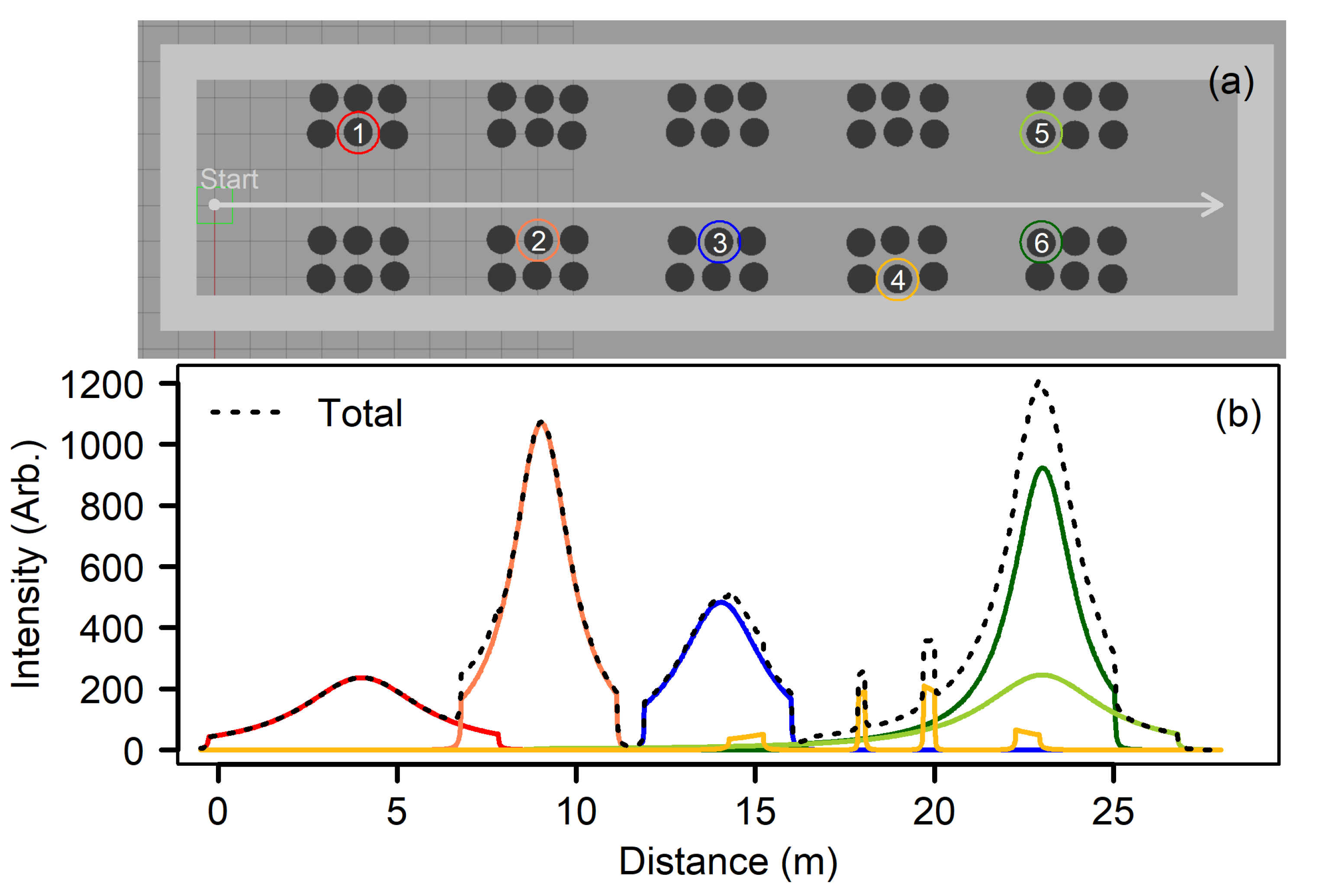
3.2. Multiple Radiation Sources in 3D

Having demonstrated the simulation can correctly model radiation intensity for a single source, performance with multiple sources was investigated. As a demonstration, six sources of equal strength were placed in an environment where they were embedded within objects representing storage drums objects. Figure 13 shows the arrangement of drums in the environment, built using the previously described world builder tools, with Figure 2g providing a template and Figure 2j as the resulting Gazebo world. Drums with radiation sources embedded are highlighted with a coloured circle and a reference number. Drums were arranged in six groups of 2 × 3, with three layers stacked on top of each other for a total of 18 drums per grouping. The sources were placed in drums at the bottom layer at the same height as the sensor, with source 3 placed in a drum 1 m above this in the middle layer. This environment is a simplified version based on a real-world waste storage facility discussed in Section 4.2.2. A pseudo sensor with uniform sensitivity traversed from left to right between the drums covering a distance of 28 m, indicated by a grey arrow.
The path taken is deliberately shifted by 1 m to be closer to the bottom row of drum arrangements. As all sources are of equal strength, it is expected that at closest approach these sources should yield greater gamma flux due to the decreased distance (e.g., source 2 compared to source 1). However, there is included some offset in where the drums are placed to represent a more realistic environment. Each drum is modelled as containing water, capable of attenuating radiation emitted from other drums, therefore producing a complex radiation field, with contributions from many sources.
Figure 13 shows the Gazebo detector intensity as a function of travel distance when only individual sources were present, and the case where all sources were present. As expected, the impact of distance is clear, with sources placed further from the sensor path registering fewer counts compared to those that were 1 m closer. Furthermore, the additional vertical distance of source 3 (≈ 1.4 m) yields a reduction in detected counts compared to source 2, demonstrating correct behaviour across three dimensions. This distance also invokes a pattern through simple geometry, where further sources subtend a greater path length before being rapidly attenuated at the shoulders of the distribution by nearby drums. For example, source 1 has an extent of ≈ 8.0 m, whereas sources 2 or 3 have a smaller extent of ≈ 4.5 m. The rapid decrease in intensity due to attenuation by other drums is not seen for sources 5 and 6, which have an unobstructed path as the detector approaches them (distance < 24 m).
It can be seen in Figure 13, with all sources present, that there are locations which demonstrate increased radiation intensity compared to the single source cases, due to the accumulative contributions from multiple sources. For example, peak intensities for sources 5 and 6 are approximately 250 and 950, respectively, whereas the peak intensity in combination is approximately 1200. Moreover, the unique features due to source 4, located in the back row of drums, are present superimposed on the broader contributions of nearby sources 5 and 6, as well as source 3.
The unique contribution from source 4 is a direct consequence of drums placed between the detector and drum containing the radiation source. These drums act to greatly attenuate emitted radiation, producing clear shine paths for gamma photons in the gaps between them, observed at roughly 15, 18, 20 and 23 m positions.
It is evident that the sensor can report the accumulative contribution of radiation intensity from multiple sources in 3D space, including for scenarios where the radiation field may be quite complex as a consequence of attenuating materials in the environment. The addition of sources can be extended beyond the six demonstrated in this experiment, and is only limited by processing capabilities of the simulation hardware. During development of these tools, it was observed that even with a greatly increased sensor update rate of 100 Hz, for realistic environments such as the drum store it was possible to include tens of sources, tens of detectors, whilst maintaining the same Gazebo real-time factor of 1.00 on a modest laptop computer with hundreds objects present in the scene. At a typical sensor update rate of 1 Hz, it is not anticipated that radiation simulation will negatively impact computational performance in the majority of cases.

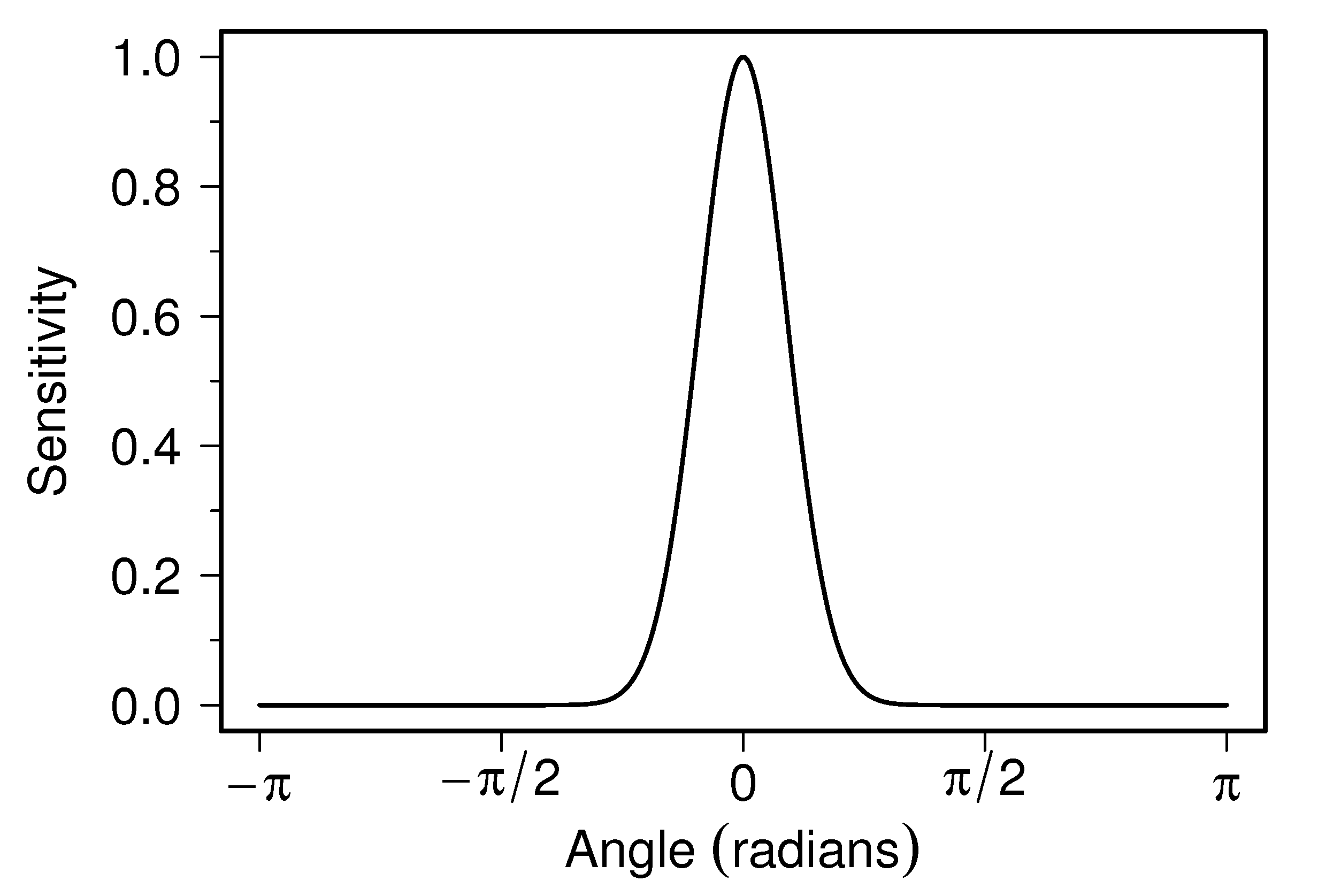
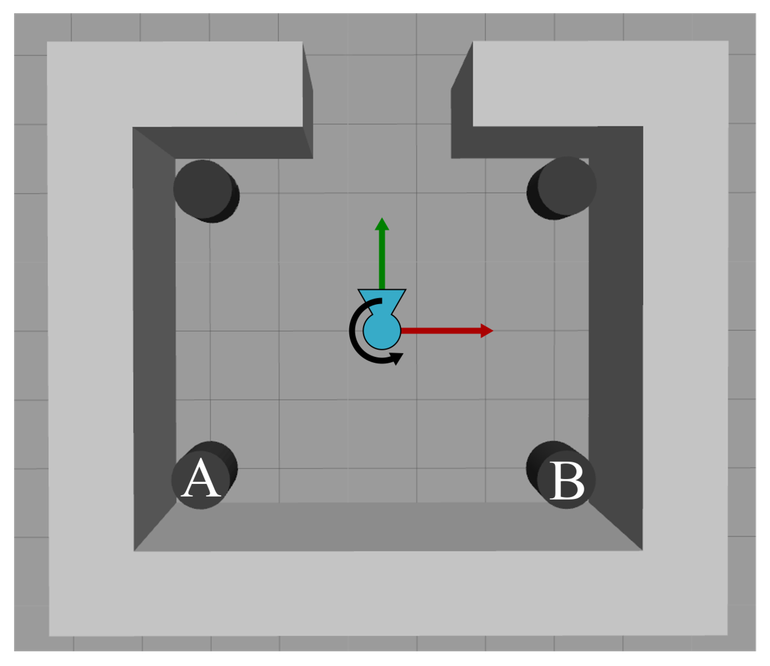
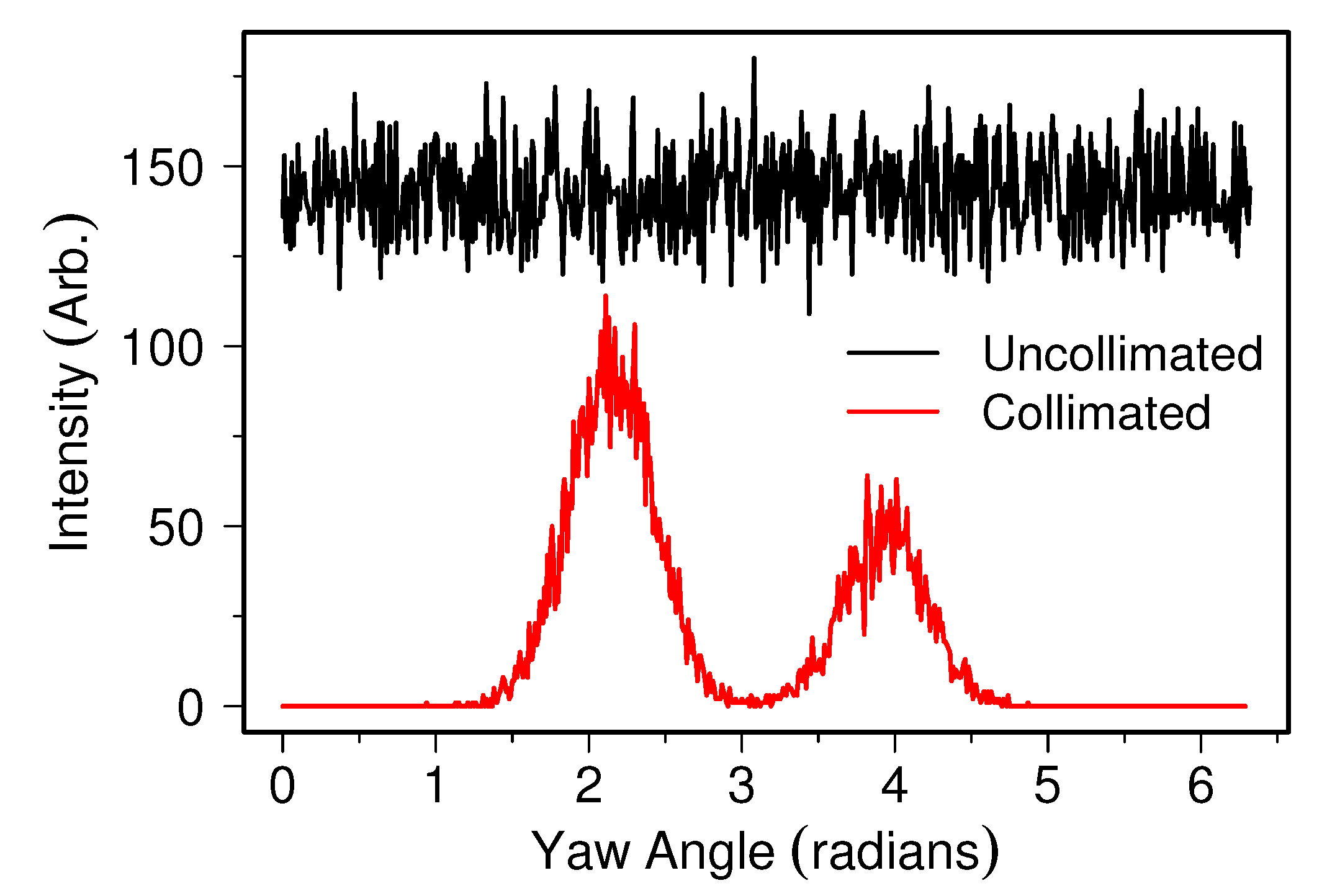
3.3. Detector Collimation Using Sensitivity Functions

Some detector designs have a high degree of sensitivity to radiation flux as a function of their geometry, producing an inherent limited field of view [52]. The use of collimation with radiation detectors may increase this anisotropy to allow for improved spatial isolation of incident particles to a more narrow field of view. This has been used on robots to aid in localisation and spectral identification of sources [42,53], including imaging of operational nuclear reactors [19]. With obvious utility to operators, this behaviour has been replicated in this work.
Miller et al. [42] demonstrate a straightforward use of a collimated LaBr 3 scintillator detector on a robot platform to provide a measure of radiation intensity as a function of robot yaw angle, therefore localising multiple sources in an environment. The following experiment emulates this capability by introducing a simple sensitivity envelope to a pseudo detector.
The sensitivity response is taken as a simple Gaussian function with full width half maximum 38 (≈ 0.28 radians), as an approximation to the detector sensitivity function as reported in [42]. The maximum response, where sensitivity is unity is aligned with the y axis of the detector, shown in Figure 14. The sensor is therefore highly insensitive to sources behind itself or at extreme angles to the sides. The sensor is also modelled with Poisson variance to mimic the random fluctuations of decay events of radioactive sources.
Figure 15 shows the sensor centred in a Gazebo environment surrounded by four drums at equal distance of 3.2 m facing the yaw = 0 direction. Drums A and B contain radiation sources, with approximate relative strength 100 and 50 counts per second, respectively, at the sensor location. This environment is modelled on mock nuclear case studies accessible through the UK National Nuclear User Facility, discussed in Section 4.2.1.
As the detector rotates in position, the field of view of the detector is directed towards different drums. Figure 16 presents the detected radiation intensity as a function of yaw angle for both uncollimated and collimated cases. In the uncollimated case, the detector always measures the cumulative contribution of the two sources. When the pseudo sensor is collimated, it is clear that the locations of individual radiation sources can be identified; moreover, it is evident the relative strength of each source is different.
Figure 16 shows the same behaviour found in [42], demonstrating that approximating collimation and detector geometric response through the use of the provided sensitivity functions performs correctly to mimic the response seen in real-world detectors on robots. Moreover, the use of a Poisson variance provides the expected fluctuation in detected radiation intensity, as evidenced by the uncollimated case.

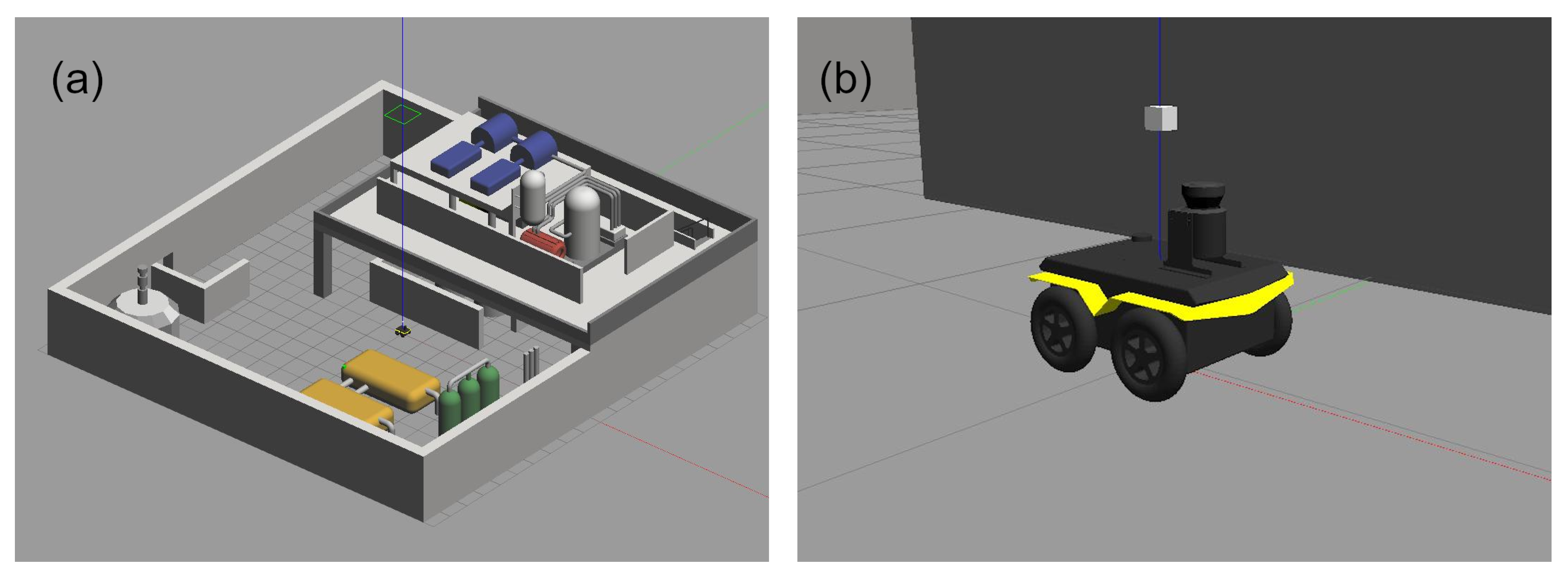
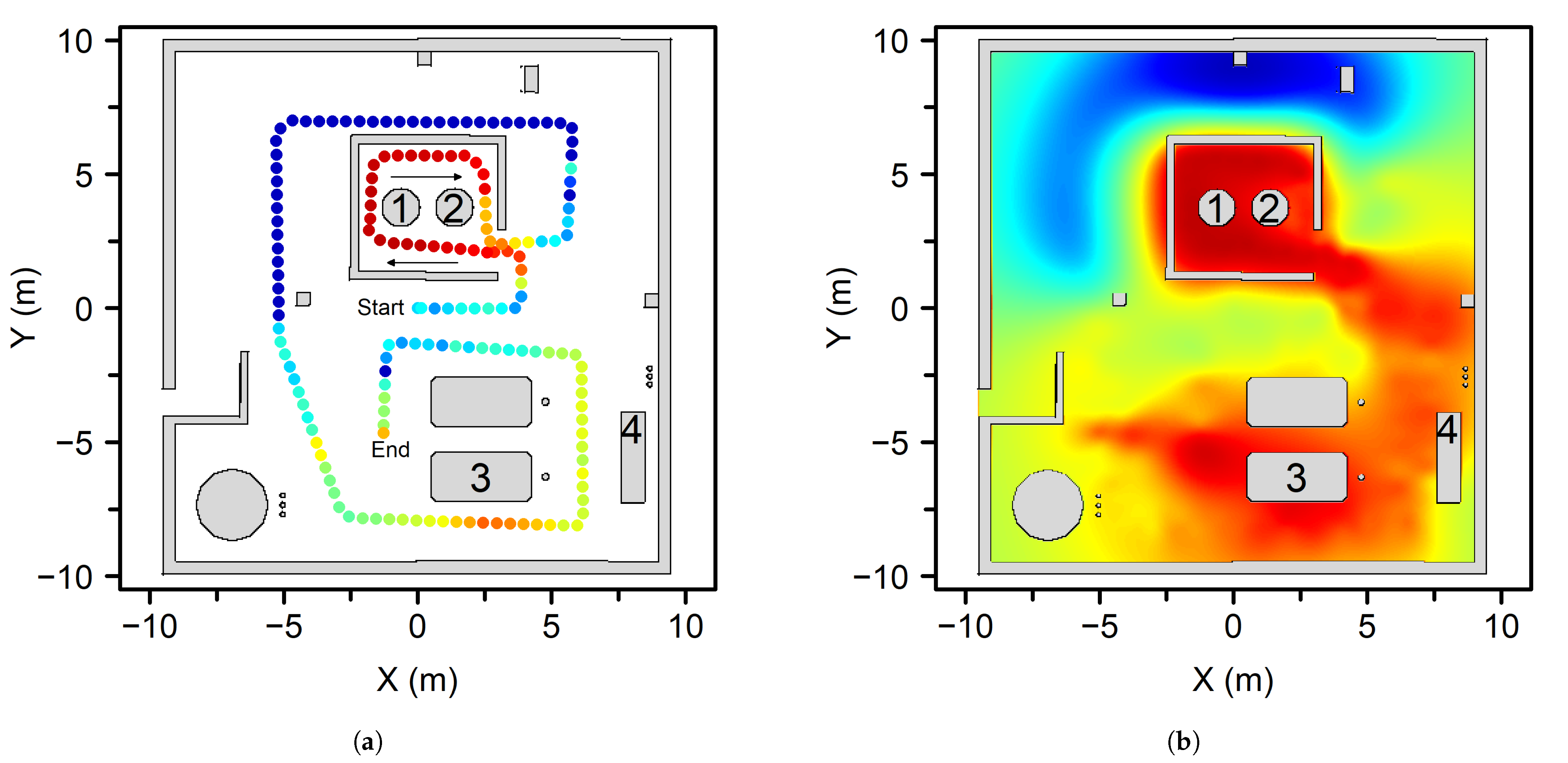
3.4. Integration with Robots in Complex Environments

Previous experiments have only showcased the sensor operating as an individual entity, traversing an environment with differing radiation field conditions. For applications and testing of robotic systems, it is necessary to demonstrate a pseudo-sensor in operation attached to a robotic platform and in a representative environment.
To this end, an uncollimated sensor with Poisson variance enabled was attached to a simulated Clearpath Jackal, with the robot manually controlled to explore an environment representative of an active nuclear facility at Sellafield Ltd, discussed in Section 4.2.3. Figure 17 shows the rendered Gazebo model of the nuclear facility, with the robot and attached sensor. The robot was limited to a maximum linear speed of 0.5 m/s, whilst the radiation sensor published observations at a rate of 1 Hz.
Radiation observations collected by the robot with its position are presented in Figure 18a. Four radiation sources were placed in the environments labelled 1–4, attached to models in the environment with varying relative activity values of 5000, 900, 500, and 200 respectively. The position of the robot, and therefore the radiation sensor, was derived using the available ROS SLAM (Simultaneous Localisation and Mapping) package Gmapping using wheel odometry, IMU (interial measurement unit), and 2D LiDAR. Blue represents a low dose rate and green through orange to red represents a higher dose rate. Materials in the environment, including the walls and the objects which housed radiation sources, all act to attenuate radiation.
The measured dose rate at a given robot location and the accumulated total dose experienced by the robot is reported in Figure 19. As the robot first approaches sources 1 and 2, there is a clear increase in local dose rate and therefore total received dose. As the robot traverses behind effective shielding concrete walls, this drops to very low levels. Once it approaches sources 3 and 4, there is again an increase in local dose rate; however, it is lower due to the proportionally lower activity sources.
The damaging influence of ionising radiation on electronics can be a concern for robotic systems developers [7,9], as such during an inspection mission it may be beneficial for a robot to avoid radiation or retreat to a safe location. By monitoring the accumulated dose received by the robot, it can be used to set thresholds for robot health and trigger autonomous behaviours, much like a human responding to alarms from a personal dosimeter. This work provides a safer means by which to develop autonomous behaviours without the requirement of exposure to actual radioactive sources, which may damage robotic systems, for prolonged periods.
Robot-collected data can be further processed in real-time or post-inspection to infer conditions in the environment, driving development of robot behaviours or for planning of future missions. For example, using the technique outlined in [5] the robot collected data in Figure 18b was interpolated onto the map of the facility to give a more intuitive description of the radiation field and its features.
This interpolated map shows hot spots in the environment around each source. Attenuation is also demonstrated, including attenuation of source 1 by the object source 2 is embedded in. Attenuation due to concrete walls is clearly visible around sources 1 and 2. The shine path of gamma radiation through the opening in the walled off area directed in the +x, −y direction has been reconstructed through interpolation. This information could inform future missions to avoid this area, travelling through areas of lower dose rate to minimise total dose.
The simulated radiation capability provided by this work has utility to be exploited for numerous robotic platform development challenges for nuclear environments. Describing the behaviour of gamma radiation from point sources accurately, and its interaction with environmental objects.

4. Discussion

4.1. Limitations of Current Implementation of Radiation

To maintain a computationally lightweight solution only a minimal viable description of radiation behaviour has been utilised. This preserves computation resources for not only running the physics simulation, which alone can become unwieldy in complex environments, but for robot algorithms and autonomy. As a result some physical assumptions must be enforced which limit the description this implementation can provide.
Firstly, all radiation sources are described as point sources. It has been previously demonstrated that radiation sources in real-world nuclear environments may be distributed or highly collimated; however, the use of only point sources greatly reduces computational overhead and is a common assumption in nuclear inspection. Users who wish to include diffuse nonpoint sources can approximate this through the use of many point sources in close proximity, a common approach in more sophisticated simulation suites [54,55,56]. As this implementation is computationally lightweight the use of many sources is possible.
The exclusion of scattering and reflections, reported in real-world nuclear environments [39,57], is also an attempt to reduce computational requirements. To include true nonpoint sources, and more importantly scattering phenomena, typically requires the need for full Monte Carlo radiation transport modelling [58], therefore ionising radiation simulations will commonly exclude this functionality to increase speed [54,55]. Despite ongoing research into ray-tracing and light transport simulations [59], they often rely on computational acceleration with dedicated graphics processing for real-time use. To be useful and run concurrently at equivalent real-time speeds of the physics simulation, this considerable escalation in hardware requirements was deemed too great to ask of users compared to the simplistic but effective offering in this work.
Users should understand however that this compromise of speed over accuracy can lead to discrepancies between simulated detector behaviour and real-world detector behaviour, which may have consequences when developing reconstruction approaches. Surfaces such as bench tops and walls may appear as weak distributed sources when in very close proximity to a source, which is not captured in this approach. Furthermore, for very strong or highly collimated sources, despite only small fractions of reflected photons from a surface, the high source intensity may lead to detection of backscattered gamma photons from surfaces large distances from a source [5]. In short, in real-world deployment, spurious scattering may lead to abundance of apparent weak or diffuse sources, but the impact on analysis is entirely dependant on the approach used.
To maintain simplicity each source is assumed to be the same isotope. The benefit being that all sources are treated as emitting mono-energetic photons; therefore, the attenuation coefficients of materials can easily be expressed as a single value. Users do not have to consider the impact of photon energy on attenuation coefficients, detector response or modelling subsequent decay pathways. If required, some aspects of this can be emulated through the construction of appropriate sensitivity functions on a per detector basis. The addition of multiple coefficients for multiple energies is not prohibited by the current methods used, and could be implemented in future work. This also means that other species (alpha, beta, neutron) could also be included in this implementation in future work.
Furthermore, each source is treated as having an individually specified constant activity in time, which is not the case for real radioactive material as the progressive decay into daughter products alters the overall activity. However, on the time scales of a single robot mission, for long lived radioisotopes this approximation holds. Short-lived isotopes such as those used for medical imaging and therapeutic treatments may be poorly represented by a fixed activity source over the duration (minutes to hours) of a robotic inspection mission. Temporal changes in background or source production, for example, during ramp-up and shut down of a reactor, cannot be directly driven by source activity.

4.2. Modelled Nuclear Environments and Challenges

The environments presented are examples of trial opportunities and real-world challenges faced by the UK nuclear sector. Common tasks include radiation field characterisation, source localisation, drum integrity monitoring (i.e., monitoring for swelling due to gas production or corrosion), inventory management (through use of barcode reading on drums), and physical reconstruction. There are also opportunities to optimise these activities as well as maintain the health of the robot through the use of autonomous behaviours. The challenge tasks presented are not intended to be exhaustive, but representative of common industrial operations, and users are encouraged to augment the environments to suit their development needs.

4.2.1. NNUF-HR Drum Store Demonstrator

The National Nuclear User Facility-Hot Robotics (NNUF-HR) builds on existing infrastructure to provide enhanced research capabilities across the UK [60]. One of its sites, based near The University of Manchester Dalton Cumbrian Facility, houses a small mock drum storage facility which can be used by researchers to demonstrate and trial robotic systems.
Having both the physical environment and its simulated digital twin available enables researchers to develop systems, sensing, algorithms, and autonomous behaviours rigorously before deploying physical hardware. The facility consists of a 5 × 5 m space, with four waste storage drums located around the space. Active sources can also be placed at locations around the facility to mimic contamination detection or general survey operations. This environment was the basis for the experiment undertaken in Section 3.3, with the generated simulation space shown in Figure 15.
Along with reconfigurable drum locations, in the space are walls and objects which attenuate radiation, therefore making mapping and localisation tasks more complex, and allowing for some variation in challenges for more robust validation. This simplified geometry makes prediction of robot behaviour easier, whilst providing enough freedom to define specific inspection challenges.
The suggested assessment for this scenario is for mobile or static manipulator robots to localise sources in the environment. Using emerging techniques such as scene data fusion [61], leverage other robotic sensing modalities to further identify which objects contain radionuclides.

4.2.2. UKAEA CCFE Drum Store

The UK Atomic Energy Authority (UKAEA) activities at their CCFE (Culham Centre for Fusion Energy) site (Oxford, UK), namely relating to Fusion research at the JET (Joint European Torus) and MAST (Mega-Amp Spherical Tokamak) facilities produce tritiated and neutron activated waste which is stored on site [62]. Furthermore, with the future FTF (Fusion Technologies Facility) and H3AT (Hydrogen-3 Advanced Technology) facilities on-site expected to handle and manage tritiated and irradiated waste [63], there is an increasing need to catalogue and monitor waste storage solutions.
The waste handling facility stores Low Level Waste (LLW) materials in UN approved 200 litre steel transport drums [64], stacked on pallets up to three units tall [65]. Each item is tagged with an identifying marker, either through laser etching or a label for tracking purposes as part of a radioactive inventory management system. The simulated space is approximately 12 × 36 m in size, with a varying number of drums arranged throughout the space.
Health monitoring of these drums is a primary concern for this facility. Deformation caused by gas accumulation, mishandling, and indications of corrosion are indicators of poor drum conditions. This information is collected and stored against the drum identifier and must be repeated at intervals as part of long-term monitoring activities. Furthermore, the does rate of each package must be assessed [62]. Figure 20 shows initial testing of a mobile robot being deployed into the drum store facility to undertake a health monitoring mission. The software tools this work provides includes the ability to subtly or drastically deform and add visual elements mimicking corrosion to models, including storage drums, in the environment. These can then be evolved over time to simulate the progress of time between survey activities.
The tasks suggested for this scenario, based on stakeholder needs, is to assess the dose rate for each new asset when it enters the facility, track the location of drums and monitor their physical health, and monitor for changes in ambient dose rate. As this is currently performed manually, automation through use of a mobile robot would be beneficial.

4.2.3. Sellafield Ltd. Inspection Challenge

The United Kingdom Nuclear Decommissioning Authority (NDA) forecast a cost in excess of GBP 200 bn over the next 120 years to address legacy and future sites across the UK [66]. To reduce both cost and time associated with decommissioning and remediation of nuclear sites, effective characterisation of environments and materials has been highlighted as a critical requirement [67].
Sellafield is the largest nuclear site in the UK and is home to some of the most difficult challenges in the NDA estate [68]. With a legacy of civil and defence operations spanning over 70 years [69], the NDA and Sellafield Ltd prioritise reduction in the highest risks, which by their nature are often complex, sometimes with limited information regarding their current state [68]. To reduce risk to human health, Sellafield Ltd have begun to adopt robotics to aid in carrying out inspection and decommissioning tasks [70].
As part of the UK EPSRC Robotics for Nuclear Environments project (EP/P01366X/1), Sellafield Ltd provided a representative facility for simulated robot deployment. This representation does not match any specific building or facility on-site, but offers an example of scales and geometry associated with active nuclear environments, including features such as pipework, vessels and stairways, and has been used previously to represent a typical nuclear facility [35].
The facility is approximately 19 m × 16 m, with a mezzanine situated in one corner 3 m above ground level. Industrial equipment and instruments are installed throughout the space, with pipe networks connecting some structures. Figure 17 shows the environment simulated in Gazebo.
The suggested trial for this environment is to map the ambient dose rate in the facility (such as Figure 18b), with the possibility of employing autonomous components to complete this task more effectively (with respect to user based heuristics e.g., time, accuracy/data quality). Furthermore, a robot should monitor its internal radiation exposure (see Figure 19), and attempt to prolong mission lifetime by reducing continued exposure through autonomous behaviours.

4.3. World Builder Tools

The tools that have been developed provide a simple way of building complex environments, such as those described in Section 4.2, for use with the Gazebo simulator on a per model basis. Figure 2 shows how the tools developed are able to offer more than the current state of the art [36,37], with its ability generate complex environments from multiple meshes and how it can make each element unique. The tools are then able to go beyond previous tools evolving the environment so that it degrades in a realistic manner and offers the integration of none visual/physical hazards, such as radiation, whilst keeping mesh densities low where possible to offer minimal impact on the physics engine.
These key benefits should aide users in development of algorithms designed for long term monitoring of changing environments, with the option of introducing environmental hazards in a realistic way, which was previously not possible.
Whilst demonstrating some possible ways of degrading an environment, the tools are not limited to only those showcased in this work, with other potential evolutionary features being trivial to implement. It is envisioned that these tools could be extended for disaster responses, such as chemical spillage or fire rescue scenarios. It is unlikely robotic platform developers will have regular access to a variety of facilities with different scenarios and hazards for extensive and repeat testing in the presence of such hazards, making these kinds of tools invaluable.

5. Conclusions

Simulation of ionising radiation allows testing and development of robotic systems, in a safe and repeatable manner. This work provides tools to rapidly develop a variety of environments and model realistic behaviour of gamma radiation and its interaction with environmental objects in real-time, inside the popular ROS compatible physics simulator Gazebo. The performance was assessed against the Monte Carlo radiation transport code MCNP6 and demonstrated correct behaviour expected for mono-energetic radiation point sources. As a simple-to-use research tool, the addition of ionising radiation in simulations can be used to rigorously assess long-term robot performance in real-world scenarios, and as such three case studies are made available by the authors based on nuclear inspection challenges in the United Kingdom.
The tools used to generate and evolve environments, along with the gazebo radiation plugin used throughout this article are available at the links provided in the Supplementary Material.

Supplementary Materials

Environment Builder Tools: https://www.github.com/EEEManchester/gazebosim_world_generator (accessed on 6 July 2021); Gazebo Radiation Plugin: https://www.github.com/EEEManchester/gazebo_radiation_plugin (accessed on 6 July 2021).

Author Contributions

Investigation, T.W.; software, T.W. and A.W.; validation and formal analysis A.W. and M.L.; writing–original draft preparation, A.W. and T.W.; supervision and writing–review and editing, B.L. and N.H. All authors have read and agreed to the published version of the manuscript.

Funding

This research was supported by UK Research and Innovation via the TORONE consortium grant number EP/P018505/1 and RAIN research hub EP/R026084/1. B.L. acknowledges support from the Royal Academy of Engineering, UK, CiET1819\13.

Institutional Review Board Statement

Not applicable.

Informed Consent Statement

Not applicable.

Data Availability Statement

Publicly available datasets were analyzed in this study. This data can be found here: https://github.com/EEEManchester/Radiation_Simulation_Data_For_MDP.git.

Conflicts of Interest

The authors declare no conflict of interest.

References

  1. Trevelyan, J.; Hamel, W.R.; Kang, S.C. Robotics in Hazardous Applications. In Springer Handbook of Robotics; Springer International Publishing: Berlin, Germany, 2016; pp. 1521–1548. [Google Scholar] [CrossRef]
  2. Tsitsimpelis, I.; Taylor, C.J.; Lennox, B.; Joyce, M.J. A review of ground-based robotic systems for the characterization of nuclear environments. Prog. Nucl. Energy 2019, 111, 109–124. [Google Scholar] [CrossRef]
  3. Bird, B.; Griffiths, A.; Martin, H.; Codres, E.; Jones, J.; Stancu, A.; Lennox, B.; Watson, S.; Poteau, X. Radiological Monitoring of Nuclear Facilities: Using the Continuous Autonomous Radiation Monitoring Assistance Robot. IEEE Rob. Autom. Mag. 2018, 1. [Google Scholar] [CrossRef]
  4. Sellafield Ltd. The 2017/18 Technology Development and Delivery Summary; Crown: London, UK, 2018. [Google Scholar]
  5. West, A.; Tsitsimpelis, I.; Licata, M.; Jazbec, A.; Snoj, L.; Joyce, M.; Lennox, B. Use of Gaussian Process Regression for Radiation Mapping of a Nuclear Reactor with a Mobile Robot. Sci. Rep. 2021. [Google Scholar] [CrossRef]
  6. Groves, K.; West, A.; Gornicki, K.; Watson, S.; Carrasco, J.; Lennox, B. MallARD: An Autonomous Aquatic Surface Vehicle for Inspection and Monitoring of Wet Nuclear Storage Facilities. Robotics 2019, 8, 47. [Google Scholar] [CrossRef] [Green Version]
  7. Zhang, K.; Hutson, C.; Knighton, J.; Herrmann, G.; Scott, T. Radiation Tolerance Testing Methodology of Robotic Manipulator Prior to Nuclear Waste Handling. Front. Robot. AI 2020, 7. [Google Scholar] [CrossRef] [PubMed] [Green Version]
  8. Aitken, J.M.; Veres, S.M.; Shaukat, A.; Gao, Y.; Cucco, E.; Dennis, L.A.; Fisher, M.; Kuo, J.A.; Robinson, T.; Mort, P.E. Autonomous Nuclear Waste Management. IEEE Intell. Syst. 2018, 33, 47–55. [Google Scholar] [CrossRef] [Green Version]
  9. Nagatani, K.; Kiribayashi, S.; Okada, Y.; Otake, K.; Yoshida, K.; Tadokoro, S.; Nishimura, T.; Yoshida, T.; Koyanagi, E.; Fukushima, M.; et al. Gamma-ray irradiation test of electric components of rescue mobile robot Quince. In Proceedings of the 2011 IEEE International Symposium on Safety, Security, and Rescue Robotics, Kyoto, Japan, 1–15 November 2011. [Google Scholar] [CrossRef]
  10. Smith, R.; Cucco, E.; Fairbairn, C. Robotic Development for the Nuclear Environment: Challenges and Strategy. Robotics 2020, 9, 94. [Google Scholar] [CrossRef]
  11. Ohashi, H.; Inaba, Y.; Nishihara, T.; Inagaki, Y.; Takeda, T.; Hayashi, K.; Katanishi, S.; Takada, S.; Ogawa, M.; Shiozawa, S. Performance test results of mock-up test facility of httr hydrogen production system. J. Nucl. Sci. Technol. 2004, 41, 385–392. [Google Scholar] [CrossRef]
  12. Kwon, K.C.; Song, S.J.; Park, W.M.; Lyu, S.P. The real-time functional test facility for advanced instrumentation and control in nuclear power plants. IEEE Trans. Nucl. Sci. 1999, 46, 92–99. [Google Scholar] [CrossRef]
  13. Kawabata, K.; Mori, F.; Shirasaki, N.; Tanifuji, Y.; Hanari, T. Towards enhancement of test facilities for supporting nuclear decommissioning by remote technology. In Proceedings of the 2017 IEEE/SICE International Symposium on System Integration (SII), Taipei, Taiwan, 11–14 December 2017. [Google Scholar] [CrossRef]
  14. Nancekievill, M.; Watson, S.; Green, P.R.; Lennox, B. Radiation Tolerance of Commercial-Off-The-Shelf Components Deployed in an Underground Nuclear Decommissioning Embedded System. In Proceedings of the 2016 IEEE Radiation Effects Data Workshop (REDW), Portland, OR, USA, 11–15 July 2016. [Google Scholar] [CrossRef]
  15. Schneider, F.E.; Welle, J.; Wildermuth, D.; Ducke, M. Unmanned multi-robot CBRNE reconnaissance with mobile manipulation System description and technical validation. In Proceedings of the 13th International Carpathian Control Conference (ICCC), High Tatras, Slovakia, 28–31 May 2012. [Google Scholar] [CrossRef]
  16. von Frankenberg, F.; McDougall, R.; Nokleby, S.; Waller, E. A Mobile Robotic Platform for Generating Radiation Maps. In Intelligent Robotics and Applications; Springer: Berlin/Heidelberg, Germany, 2012; pp. 407–416. [Google Scholar] [CrossRef]
  17. Guzman, R.; Navarro, R.; Ferre, J.; Moreno, M. RESCUER: Development of a Modular Chemical, Biological, Radiological, and Nuclear Robot for Intervention, Sampling, and Situation Awareness. J. Field Robot. 2015, 33, 931–945. [Google Scholar] [CrossRef]
  18. Sharp, A.; Kruusamae, K.; Ebersole, B.; Pryor, M. Semiautonomous dual-arm mobile manipulator system with intuitive supervisory user interfaces. In Proceedings of the 2017 IEEE Workshop on Advanced Robotics and its Social Impacts (ARSO), Austin, TX, USA, 8–10 March 2017. [Google Scholar] [CrossRef]
  19. Tsitsimpelis, I.; West, A.; Licata, M.; Aspinall, M.D.; Jazbec, A.; Snoj, L.; Martin, P.A.; Lennox, B.; Joyce, M.J. Simultaneous, Robot-Compatible γ-Ray Spectroscopy and Imaging of an Operating Nuclear Reactor. IEEE Sens. J. 2021, 21, 5434–5443. [Google Scholar] [CrossRef]
  20. Koenig, N.; Howard, A. Design and use paradigms for gazebo, an open-source multi-robot simulator. In Proceedings of the 2004 IEEE/RSJ International Conference on Intelligent Robots and Systems (IROS), Sendai, Japan, 28 September–2 October 2004. [Google Scholar] [CrossRef] [Green Version]
  21. Stepney, S.; Polack, F.A. Engineering Simulations as Scientific Instruments: A Pattern Language; Springer International Publishing: Cham, Switzerland, 2018. [Google Scholar] [CrossRef]
  22. International Atomic Energy Agency. Robotics Challenge 2017. Available online: https://www.iaea.org/topics/safeguards-in-practice/robotics-challenge-2017 (accessed on 25 June 2021).
  23. European Robotics. ENRICH—The European Robotics Hackathon. Available online: https://enrich.european-robotics.eu/ (accessed on 25 June 2021).
  24. FIS 360. Game Changers Challenges. Available online: https://www.gamechangers.technology/challenge (accessed on 25 June 2021).
  25. Fukushima Innovation Coast Initiative Promotion Organization. Fukushima Robot Test Field [Japanese]. Available online: https://www.fipo.or.jp/robot/overview (accessed on 25 June 2021).
  26. Bagatin, M. Ionizing Radiation Effects in Electronics: From Memories to Imagers; CRC Press: Boca Raton, FL, USA, 2016. [Google Scholar] [CrossRef]
  27. George, J.S. An overview of radiation effects in electronics. In AIP Conference Proceedings; American Institute of Physics Inc.: College Park, MD, USA, 2019; Volume 2160, p. 060002. [Google Scholar] [CrossRef]
  28. Kawatsuma, S.; Fukushima, M.; Okada, T. Emergency response by robots to Fukushima-Daiichi accident: Summary and lessons learned. Ind. Robot. Int. J. 2012, 39, 428–435. [Google Scholar] [CrossRef]
  29. Wu, Y. CLEAR-S: An integrated non-nuclear test facility for China lead-based research reactor. Int. J. Energy Res. 2016, 40, 1951–1956. [Google Scholar] [CrossRef] [Green Version]
  30. Kawabata, K.; Suzuki, K.; Isowa, M.; Horiuchi, K.; Ito, R. Development of a robot simulation system for remotely operated robots for operator proficiency training and robot performance verification. In Proceedings of the 2017 14th International Conference on Ubiquitous Robots and Ambient Intelligence (URAI), Jeju, Korea, 28 June–1 July 2017. [Google Scholar] [CrossRef]
  31. Kawabata, K.; Suzuki, K. Development of a Robot Simulator for Remote Operations for Nuclear Decommissioning. In Proceedings of the 2019 16th International Conference on Ubiquitous Robots (UR) IEEE, Jeju, Korea, 24–27 June 2019. [Google Scholar] [CrossRef]
  32. Michel, O. Webots: Symbiosis between virtual and real mobile robots. In Lecture Notes in Computer Science; Including Subseries Lecture Notes in Artificial Intelligence and Lecture Notes in Bioinformatics; Springer: Berlin/Heidelberg, Germany, 1998; Volume 1434, pp. 254–263. [Google Scholar] [CrossRef]
  33. Rohmer, E.; Singh, S.P.N.; Freese, M. CoppeliaSim (formerly V-REP): A Versatile and Scalable Robot Simulation Framework. In Proceedings of the International Conference on Intelligent Robots and Systems (IROS), Tokyo, Japan, 3–7 November 2013. [Google Scholar]
  34. Noori, F.M.; Portugal, D.; Rocha, R.P.; Couceiro, M.S. On 3D simulators for multi-robot systems in ROS: MORSE or Gazebo? In Proceedings of the SSRR 2017 15th IEEE International Symposium on Safety, Security and Rescue Robotics, Shanghai, China, 11–13 October 2017; pp. 19–24. [Google Scholar] [CrossRef]
  35. Pitonakova, L.; Giuliani, M.; Pipe, A.; Winfield, A. Feature and Performance Comparison of the V-REP, Gazebo and ARGoS Robot Simulators. In Towards Autonomous Robotic Systems; Springer International Publishing: Cham, Switzerland, 2018; pp. 357–368. [Google Scholar] [CrossRef] [Green Version]
  36. Lavrenov, R.; Zakiev, A. Tool for 3D Gazebo map construction from arbitrary images and laser scans. In Proceedings of the 2017 10th International Conference on Developments in eSystems Engineering (DeSE), Paris, France, 14–16 June 2017; pp. 256–261. [Google Scholar]
  37. Abbyasov, B.; Lavrenov, R.; Zakiev, A.; Yakovlev, K.; Svinin, M.; Magid, E. Automatic tool for Gazebo world construction: From a grayscale image to a 3D solid model. In Proceedings of the 2020 IEEE International Conference on Robotics and Automation (ICRA), Paris, France, 31 May–31 August 2020; pp. 7226–7232. [Google Scholar]
  38. Connor, D.; Martin, P.G.; Scott, T.B. Airborne radiation mapping: Overview and application of current and future aerial systems. Int. J. Remote Sens. 2016, 37, 5953–5987. [Google Scholar] [CrossRef]
  39. Knoll, G.F. Radiation Detection and Measurement, 4th ed.; John Wiley & Sons: Hoboken, NJ, USA, 2010. [Google Scholar]
  40. Dehnen, W.; Read, J.I. N-body simulations of gravitational dynamics. Eur. Phys. J. Plus 2011, 126. [Google Scholar] [CrossRef]
  41. Hubbell, J.; Seltzer, S. Tables of X-ray Mass Attenuation Coefficients and Mass Energy-Absorption Coefficients (Version 1.4). 2004. Available online: http://physics.nist.gov/xaamdi (accessed on 25 June 2021).
  42. Miller, A.; Machrafi, R.; Mohany, A. Development of a semi-autonomous directional and spectroscopic radiation detection mobile platform. Radiat. Meas. 2015, 72, 53–59. [Google Scholar] [CrossRef] [Green Version]
  43. Machado, D.M.; Cotelli, A.; Galvão, D.; Mól, A.C.; Carvalho, P.V.; Vidal, M.C.R. Use Dosimetry Virtual Tool for Security Studies Physics and Nuclear. Procedia Manuf. 2015, 3, 1765–1771. [Google Scholar] [CrossRef]
  44. Bridgwater, T.; Giuliani, M.; van Maris, A.; Baker, G.; Winfield, A.; Pipe, T. Examining Profiles for Robotic Risk Assessment. In Proceedings of the 2020 ACM/IEEE International Conference on Human-Robot Interaction ACM, Cambridge, UK, 24–26 March 2020. [Google Scholar] [CrossRef] [Green Version]
  45. West, C.; Arvin, F.; Cheah, W.; West, A.; Watson, S.; Giuliani, M.; Lennox, B. A Debris Clearance Robot for Extreme Environments. In Towards Autonomous Robotic Systems; Springer International Publishing: Cham, Switzerland, 2019; pp. 148–159. [Google Scholar] [CrossRef]
  46. Baca, T.; Jilek, M.; Manek, P.; Stibinger, P.; Linhart, V.; Jakubek, J.; Saska, M. Timepix Radiation Detector for Autonomous Radiation Localization and Mapping by Micro Unmanned Vehicles. In Proceedings of the 2019 IEEE/RSJ International Conference on Intelligent Robots and Systems (IROS), Macau, China, 3–8 November 2019. [Google Scholar] [CrossRef]
  47. Marques, L.; Vale, A.; Vaz, P. State-of-the-Art Mobile Radiation Detection Systems for Different Scenarios. Sensors 2021, 21, 1051. [Google Scholar] [CrossRef]
  48. Groves, K.; Hernandez, E.; West, A.; Wright, T.; Lennox, B. Robotic Exploration of an Unknown Nuclear Environment Using Radiation Informed Autonomous Navigation. Robotics 2021, 10, 78. [Google Scholar] [CrossRef]
  49. Werner, C.J.; Bull, J.S.; Solomon, C.J.; Brown, F.B.; McKinney, G.W.; Rising, M.E.; Dixon, D.A.; Martz, R.L.; Hughes, H.G.; Cox, L.J.; et al. MCNP Version 6.2 Release Notes. In Technical Report LA-UR-18-20808; Los Alamos National Laboratory: Los Alamos, NM, USA, 2018. [Google Scholar]
  50. Werner, C.J. (Ed.) MCNP Users Manual-Code Version 6.2. In Technical Report LA-R-17-29981; Los Alamos National Laboratory: Los Alamos, NM, USA, 2017. [Google Scholar]
  51. Connor, D.T.; Wood, K.; Martin, P.G.; Goren, S.; Megson-Smith, D.; Verbelen, Y.; Chyzhevskyi, I.; Kirieiev, S.; Smith, N.T.; Richardson, T.; et al. Radiological Mapping of Post-Disaster Nuclear Environments Using Fixed-Wing Unmanned Aerial Systems: A Study From Chornobyl. Front. Robot. AI 2020, 6. [Google Scholar] [CrossRef] [Green Version]
  52. Ardiny, H.; Witwicki, S.; Mondada, F. Autonomous Exploration for Radioactive Hotspots Localization Taking Account of Sensor Limitations. Sensors 2019, 19, 292. [Google Scholar] [CrossRef] [Green Version]
  53. Sato, Y.; Terasaka, Y.; Utsugi, W.; Kikuchi, H.; Kiyooka, H.; Torii, T. Radiation imaging using a compact Compton camera mounted on a crawler robot inside reactor buildings of Fukushima Daiichi Nuclear Power Station. J. Nucl. Sci. Technol. 2019, 56, 801–808. [Google Scholar] [CrossRef]
  54. Szőke, I.; Louka, M.N.; Bryntesen, T.R.; Bratteli, J.; Edvardsen, S.T.; RøEitrheim, K.K.; Bodor, K. Real-time 3D radiation risk assessment supporting simulation of work in nuclear environments. J. Radiol. Prot. 2014, 34, 389–416. [Google Scholar] [CrossRef] [Green Version]
  55. Caracena, T.M.; Goncalves, J.G.M.; Peerani, P.; Vidal, E.V. A Variable Point Kernel Dosimetry Method for Virtual Reality Simulation Applications in Nuclear Safeguards and Security. IEEE Trans. Nucl. Sci. 2013, 60, 3862–3871. [Google Scholar] [CrossRef] [Green Version]
  56. Yang, L.; Liu, Y.; Peng, M.; Ayodeji, A.; Chao, N. Voxel-based point kernel method for dose rate assessment of non-uniform activity and self-shielding sources in nuclear facility decommissioning. Radiat. Phys. Chem. 2019, 164, 108381. [Google Scholar] [CrossRef]
  57. Jazbec, A.; Kos, B.; Ambrožič, K.; Snoj, L. Dose rate calculations at beam tube no. 5 of the JSI TRIGA mark II research reactor using Monte Carlo method. Appl. Radiat. Isot. 2021, 168, 109510. [Google Scholar] [CrossRef]
  58. Agostinelli, S.; Allison, J.; Amako, K.; Apostolakis, J.; Araujo, H.; Arce, P.; Asai, M.; Axen, D.; Banerjee, S.; Barrand, G.; et al. Geant4—A simulation toolkit. Nucl. Instrum. Meth. A 2003, 506, 250–303. [Google Scholar] [CrossRef] [Green Version]
  59. Baranoski, G.V.; Krishnaswamys, A. Light & Skin Interactions: Simulations for Computer Graphics Applications; Morgan Kaufmann Publishers: Burlington, MA, USA, 2010. [Google Scholar]
  60. National Nuclear Users Facility. Hot Robotics Facility. Available online: https://www.nnuf.ac.uk/hot-robotics (accessed on 25 June 2021).
  61. Vetter, K.; Barnowski, R.; Cates, J.W.; Haefner, A.; Joshi, T.H.; Pavlovsky, R.; Quiter, B.J. Advances in Nuclear Radiation Sensing: Enabling 3-D Gamma-Ray Vision. Sensors 2019, 19, 2541. [Google Scholar] [CrossRef] [Green Version]
  62. Reynolds, S.; Newman, M.; Coombs, D.; Witts, D. JET experience on managing radioactive waste and implications for ITER. Fusion Eng. Des. 2016, 109–111, 979–985. [Google Scholar] [CrossRef]
  63. Chapman, I.T.; Morris, A.W. UKAEA capabilities to address the challenges on the path to delivering fusion power. Philos. Trans. R. Soc. A 2019, 377, 20170436. [Google Scholar] [CrossRef]
  64. Bell, A.C.; Williams, J.; Neilson, J.D.; Perevezentsev, A. Detritiation Processes Needed for JET Operation and Their Wider Applicability. Fusion Sci. Technol. 2002, 41, 626–631. [Google Scholar] [CrossRef]
  65. Bayram, H. Remote Inspection Working Group (RIWG) Trials in Drummed Waste Store. Available online: https://rainhub.org.uk/remote-inspection-working-group-riwg-trials-in-drummed-waste-store/ (accessed on 25 June 2021).
  66. Nuclear Decommissioning Authority. Nuclear Decommissioning Authority Annual Report and Accounts 2017/18; Dandy Booksellers Ltd.: London, UK, 2018. [Google Scholar]
  67. Nuclear Decommissioning Authority. Nuclear Decommissioning Authority Strategy: Strategy Effective from April 2016; The Stationery Office: London, UK, 2016. [Google Scholar]
  68. Nuclear Decommissioning Authority. The Nuclear Decommissioning Authority: Progress with Reducing Risk at Sellafield; National Audit Office: London, UK, 2018. [Google Scholar]
  69. Sellafield Ltd. Cleaning Up Sellafield: Annual Review 2017/18. Available online: https://www.gov.uk/government/publications/sellafield-ltd-publishes-201718-annual-review-of-performance (accessed on 25 June 2021).
  70. Sellafield Ltd. Annual Review of Performance 2016/17. Available online: https://www.gov.uk/government/publications/annual-review-of-performance-201617 (accessed on 25 June 2021).
Figure 1. Steps required to generate a custom environment for Gazebo.
Robotics 10 00086 g001
Figure 2. Example of how a representative images and CAD models can be used to create a simulation environment. Inputs are shown above with the resulting model shown below for each pair. Sub-figure pairs (a,d) show a storage facility, (b,e) a challenge environment used in Section 4.2.1, (c,f) the representative drum store used in Section 4.2.2, (g,j) a corridor of barrels used in Section 3.2, (h,k) depict an office environment using custom models as building blocks and (i,l) show a CAD model of a representative nuclear facility used in Section 4.2.3.
Robotics 10 00086 g002
Figure 3. Steps required to generate a environment with unique models.
Robotics 10 00086 g003
Figure 4. Stochastic deformation of exported barrel model, adding noise to the vertices in the model to make each barrel unique.
Robotics 10 00086 g004
Figure 5. Example of model with low density mesh being modified for use with physical deformation tools.
Robotics 10 00086 g005
Figure 6. Steps required to evolve environment for Gazebo.
Robotics 10 00086 g006
Figure 7. Examples of object and environmental evolution between simulation iterations.
Robotics 10 00086 g007
Figure 8. Evolved of the simple world created in Figure 2e.
Robotics 10 00086 g008
Figure 9. Example of integration of world builder materials and radiation sensors/sources plugin. Radiation locations have been highlighted and colour coded as green, yellow and red to show low, medium and high level radiation sources, respectively.
Robotics 10 00086 g009
Figure 10. Example of issues facing robotic inspection tasks, with multiple radiation sources, detector sensitivity profiles and unknown environments.
Robotics 10 00086 g010
Figure 11. Log radiation intensity as a function of distance and attenuation due to objects from Gazebo simulation. Single point source located at ( 0 , 0 ) , marked with a cross. A and B have attenuation coefficients of water, C is concrete. Colour scaling has been augmented for clarity, with high values (> 3.5 ) set to red.
Robotics 10 00086 g011
Figure 12. A comparison of radiation intensity as a function of distance and attenuation due to objects between Gazebo and MCNP.
Robotics 10 00086 g012
Figure 13. (a) Top view of Gazebo environment with drums in arrangements of three by two, stacked three units high. Drums emitting radiation are highlighted with a coloured circles. (b) Measured radiation intensity for each source individually and with all sources present.
Robotics 10 00086 g013
Figure 14. Gaussian sensitivity function used with collimated pseudo detector.
Robotics 10 00086 g014
Figure 15. Collimated detector represented as a blue icon with four drums in Gazebo. Drums A and B contain simulated radioactive sources.
Robotics 10 00086 g015
Figure 16. Measured detector intensity with respect to yaw angle, with two radiation sources present.
Robotics 10 00086 g016
Figure 17. Gazebo representation of a Sellafield Ltd facility (a), with close up of Clearpath Jackal robot with attached sensor location indicated with a grey cube (b).
Robotics 10 00086 g017
Figure 18. (a) Point radiation count rate observations in a representative nuclear facility. Blue indicates low count rate, red indicates high count rate. (b) Interpolated radiation map from point measurements, radiation sources and their shine paths are more readily visible.
Robotics 10 00086 g018
Figure 19. Dose rate and accumulative dose during the nuclear inspection task.
Robotics 10 00086 g019
Figure 20. Photograph of a mobile robot undertaking teleoperated inspection of the CCFE drum store, equipped with visual, 3D reconstruction, and radiation detection instrumentation.
Robotics 10 00086 g020
Publisher’s Note: MDPI stays neutral with regard to jurisdictional claims in published maps and institutional affiliations.

