Article

Nut Unfastening by Robotic Surface Exploration

1
Extreme Robotics Laboratory, School of Metallurgy & Materials Science, University of Birmingham, Birmingham B15 2TT, UK
2
The Faraday Institution, Quad One, Harwell Science and Innovation Campus, Didcot OX11 0RA, UK
*
Author to whom correspondence should be addressed.
Rastegarpanah and Ner are the joint first authors of this work.
Robotics 2021, 10(3), 107; https://doi.org/10.3390/robotics10030107
Submission received: 14 July 2021 / Revised: 3 September 2021 / Accepted: 10 September 2021 / Published: 14 September 2021
(This article belongs to the Special Issue Control of Robots Physically Interacting with Humans and Environment)

Abstract

:
In this paper, we present a novel concept and primary investigations regarding automated unfastening of hexagonal nuts by means of surface exploration with a compliant robot. In contrast to the conventional industrial approaches that rely on custom-designed motorised tools and mechanical tool changers, we propose to use robot fingers to position, grasp and unfasten unknown random-sized hexagonal nuts, which are arbitrarily positioned in the robot’s task space. Inspired by how visually impaired people handle unknown objects, in this work, we use information observed from surface exploration to devise the unfastening strategy. It combines torque monitoring with active compliance for the robot fingers to smoothly explore the object’s surface. We implement a shape estimation technique combining scaled iterative closest point and hypotrochoid approximation to estimate the location as well as contour profile of the hexagonal nut so as to accurately position the gripper fingers. We demonstrate this work in the context of dismantling an electrically driven vehicle battery pack. The experiments are conducted using a seven degrees of freedom (DoF)–compliant robot fitted with a two-finger gripper to unfasten four different sized randomly positioned hexagonal nuts. The obtained results suggest an overall exploration and unfastening success rate of 95% over an average of ten trials for each nut.

1. Introduction

Day-by-day increase in the use of electrically driven vehicles will eventually lead to an increase in the number of depleted lithium-ion batteries (LIBs) to recycle. This is one of the major challenges at the forefront of automotive industries [1]. Unfastening hexagonal nuts to dismantle LIB components as well as to separate storage cells is a crucial step in this recycling process. Currently, this is being performed manually by trained workers, who follow safety protocols while dismantling. Nevertheless, this is hazardous in that poisonous gasses along with flames are released in the case of any un-discharged cell explosion. One way to deal with this is by robotising the dismantling process. This not only increases the safety levels, but also reduces the operating costs. In this context, in contrast to the conventional methods using motorised screwdrivers, we propose a surface exploration-based strategy to unfasten arbitrarily positioned random-sized hexagonal bolts by means of a collaborative robot fitted with a parallel jaw gripper as seen in Figure 1.
Industrial automation methods rely on highly structured environments in which robots make pre-programmed repetitive actions with respect to exactly known objects in fixed positions. Nevertheless, developing flexible robotic systems that can be generalised to a variety of objects and can handle uncertainties remains a major challenge at the frontier of AI and vision research. For the task of (un-)fastening, a popular option is to use motorised tools or wrenches that are mounted on the robot end effectors. To this extent, Jia et al. [2] investigated automated fastening strategies for assembly, while Li et al. believed these strategies to not be directly applicable for disassembly [3]. Unbolting during disassembly comes with positional or orientation uncertainties, due to the initial assembly process or in-life usage. The size and shape of the bolt or nut might change over time, due to various factors, such as friction, force, and temperature. Consequently, their threads might become distorted in-use. Different approaches have been proposed to tackle the uncertainties of unfastening: focusing on using advanced machine vision and control algorithms [4,5]; developing special-purpose tools [6,7]; or, proposing a sequential robotic framework [3]. Nevertheless, the main problem still persists, i.e., obtaining a generalised approach that can handle nuts with a variety of sizes and thickness and can accomplish the task with decent positioning accuracy.
In this paper, we present a robotic framework that can perform the unfastening of hexagonal nuts by means of a two-finger gripper. Inspired by how visually impaired people handle unknown objects, in this work, we use information observed from surface exploration to devise the unfastening strategy, i.e., to identify the position of the nut and suitable faces to position the gripper fingers. We rely on tactile information rather than vision to eliminate any uncertainties caused due to perception. Moreover, these objects are texture-less and reflective, which makes them difficult to recognise or track using vision. Overall, the main contributions of this work are as follows:
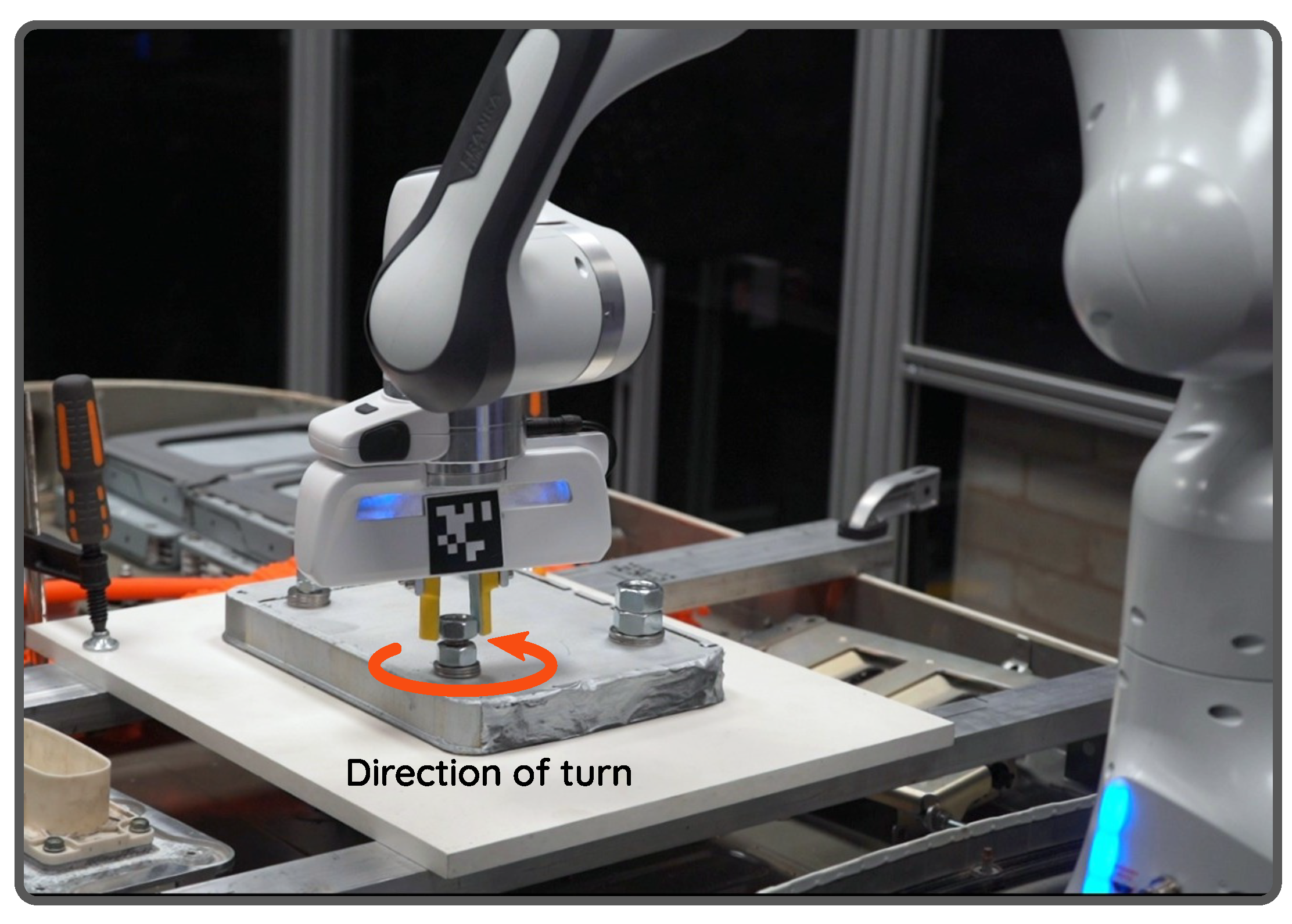
  • We have developed a decentralised and generalised framework for nut unfastening. In contrast to the existing conventional methodologies that use motorised screwdrivers, our approach uses robot fingers. This makes our approach agnostic to the size of the nut. To the best of our knowledge, no known studies have ever performed this task using robot fingers.
  • We have developed a surface exploration control strategy combining torque monitoring with active compliance in order to guide the robot fingers to explore the task space. The positional data observed from this step are used by our contact modelling scheme to identify the location of the nut. For the sake of contact modelling, a scaling iterative closest point (SICP) technique along with hypotrochoid approximation is integrated with our exploration scheme. This allows us to identify suitable faces to accurately position robot fingers to grasp and rotate sequentially to accomplish unfastening.
We perform experiments validating our approach by unfastening multiple nuts that are of different sizes and are positioned arbitrarily in the robot task space. It is worth noting that the nut sizes are not known a priori and are estimated during the trial. A seven degrees of freedom (DoF) robot fitted with a two-finger hand is used for this purpose. The major benefit of our approach is that it eliminates the need for additional expensive special-purpose hardware, such as mechanical tool changers and unfastening tools. In addition, it is easy to generalise to a variety of nuts as long as the size fits within the maximum gripper stroke. The experiments performed in our laboratory environment emulate the real EV battery recycling setup.
In the remainder of this paper, Section 2 surveys the related approaches. Section 3 presents the developed unfastening methodology. Section 4 reports the experiments conducted to validate the proposed method and discusses the performance of the system. Finally, Section 5 concludes the paper.

2. Related Work

The potential for flexible robotic systems has been studied for a long time and a significant amount of research is being carried out on this topic. Previously, robotised fastening or unfastening was studied in the literature as a key task in both assembly and dismantling processes. Different strategies are proposed for automating this task. One of the earliest works by Apley et al. presents an approach to diagnose the actual state of the system while unfastening a screw [8]. He concluded that the unscrewing torque is the most reliable signal to interpret the state of the robot during unfastening. Later, Zuo et al. developed a custom-designed screwnail for unscrewing to overcome the geometrical uncertainties of a handled product [9]. However, it is not clear whether any of these methods can provide a reliable solution if the screw is too tight to move.
Various approaches have been made available in the literature for robotising screw or nut unfastening [3,7,10,11,12]. Very recently, Li et al. proposed a sequence of actions with a cobot to unscrew a hexagonal headed screw in which the robot performs a spiral search motion in order to engage an electric nutrunner onto the screw [3]. A “peg-in-hole” style controller with torque monitoring was used to position the tool to hold the screw. However, it is not clear whether their system can handle screws of different sizes without a tool change. A similar approach with a new bit-changing mechanism for unscrewing is presented in [7]. A torque estimation method using a wrench held by a three-finger hand is presented in [13]. Although the used setup is interesting to perform nut fastening tasks, the work focuses only on estimating forces for industrial robots without joint torque sensors. Recently, Pfeiffer et al. presented a robotic system centred on a humanoid platform, using a motorised wrench tool to demonstrate nut fastening [14]. Like ours, their system uses visual servoing to navigate the robot towards the desired object, and then switches to admittance control to position and fasten nuts. There are other special-purpose systems designed for various screw-related tasks. A visual servoing-based fastening robot is presented in [15]. Similarly, a mobile fastening robotic system is presented in [16]. Although most of these systems are flexible, they lack generalisation for nut sizes and often require additional hardware to change tools. Apart from these, some works targeted the designing of special-purpose fastening tools for robots. One such tool is presented in [17]. We refer the reader to [18] for more interesting nut-fastening tools. In addition, a few works presented intelligent control strategies to accomplish nut fastening. In this regard, a fuzzy logic-based controller is presented in [19] and a neural network-based monitoring schema for screw fastening is presented in [20].
In contrast to the aforementioned approaches, inspired by the way humans perform unbolting using their fingers, our approach uses the robot’s gripper fingers to unfasten a nut. Moreover, most of the previous studies have used external force-torque sensors to measure the interaction force between the robot end effector and the screw. However, in this study, as a step towards reducing the setup costs, we rely only on the measured joint torques. The required torque at the beginning of the unbolting process is high, while this amount is very low at the disengage point, where the nut is completely removed from the bolt’s threads. Identifying the required torque for unbolting requires a robust control strategy. Within this context, Mironov et al. developed a force-based control strategy for robotic unscrewing in which the data are extracted from a skilled human during manual screwing and unscrewing [11]. Estimating the nut’s tightening torque is also a challenging task for the robot. To solve this problem, Berger et al. proposed an experience-based framework that does not need pre-knowledge about the robot platform by training the sensor data to learn the task models [13]. However, this method cannot be generalised, as the robot configuration must be the same in both offline training and online training. In [3], Li et al. proposed a control strategy combining torque and position monitoring with active compliance in which the untightening torque is produced by a force-feedback nutrunner and the torque feedback monitored by the end effector of a cobot during various stages of unfastening (i.e., approach, search and engage, unfasten, and assess).

3. Materials and Methods

In this section, we present the technical details of our method. As mentioned before, we use the tactile information to model the shape of the nut and devise a strategy to grasp and unfasten a hexagonal nut. The proposed pipeline, depicted in Figure 2, consists of the following modules: system initialisation, where the robot is visually guided into the task-space; data acquisition where the robot starts exploring the scene and collects contact positional data; contact modelling where the nut pattern and its position are identified from the acquired data; and finally, task execution, where the robot is commanded to perform nut unfastening by executing a sequence of motions. These are presented below.

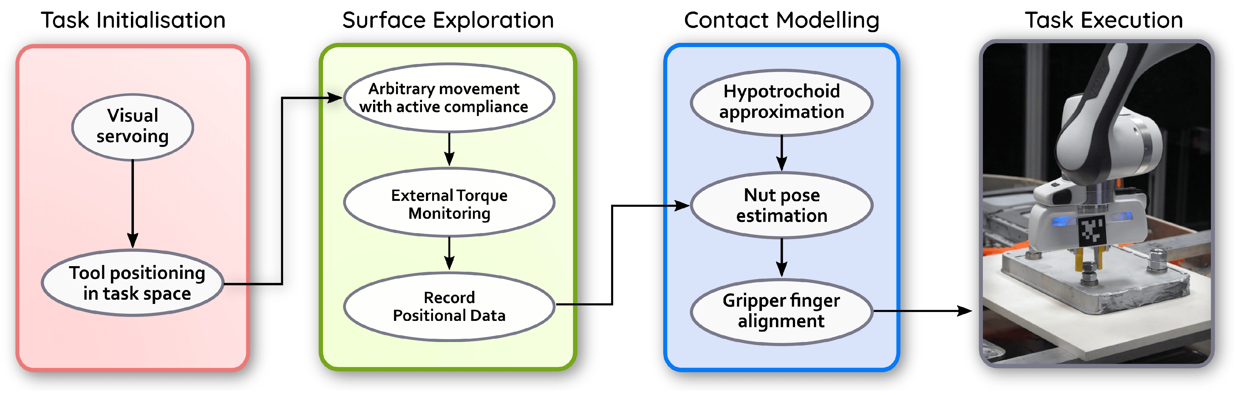
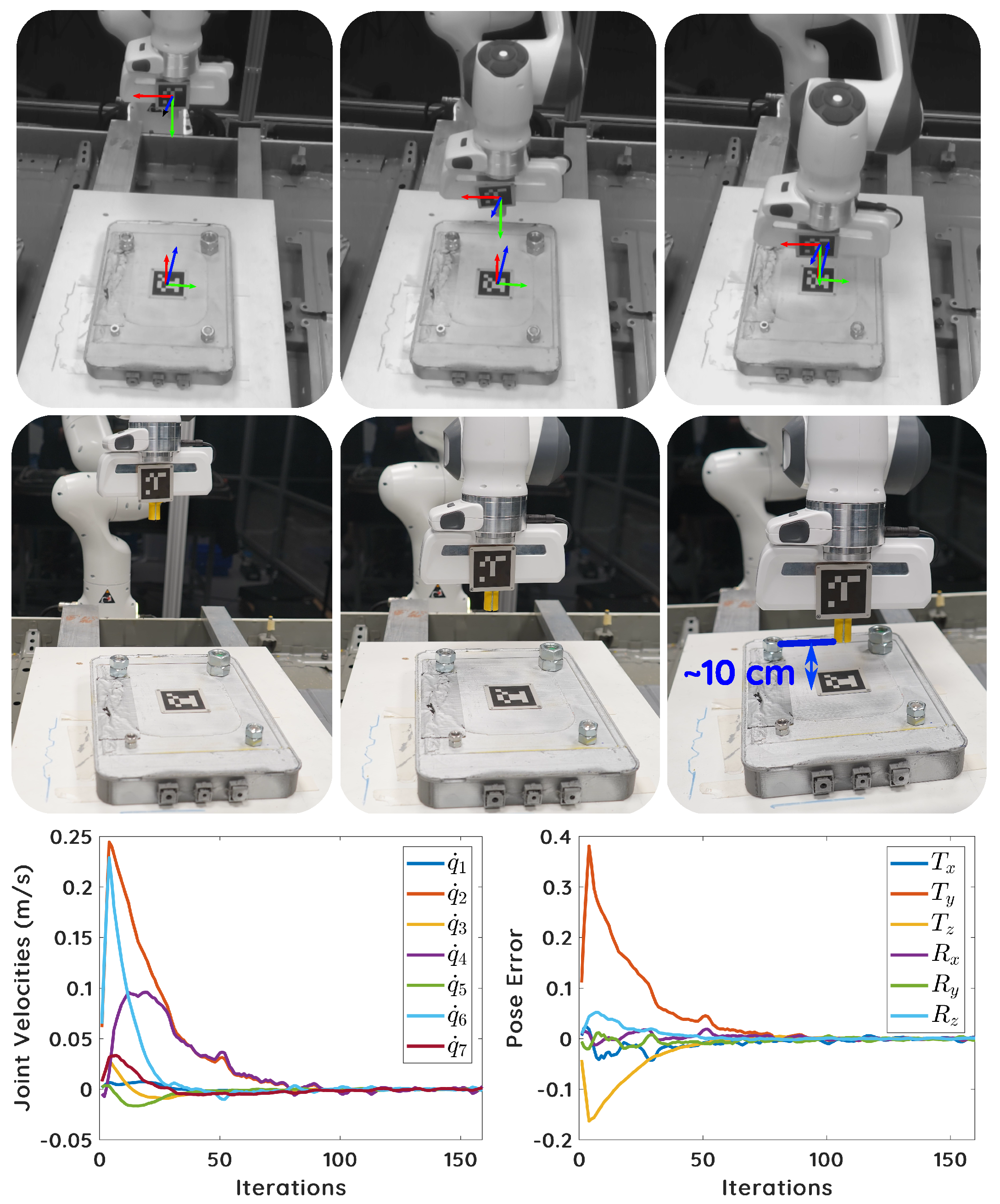
3.1. Guiding the Robot into Task-Space

The first step in our pipeline is to position the robot at a pose from where it can start the surface exploration. For this work, we consider a pose where the robot end effector (two-finger hand) is at the height of 10 cm above the task object as our initial pose. Although a human operator can perform this task by hand-guidance, to maintain the safety protocol, we use a conventional pose-based visual servoing method based on fiducial marker tracking. Alternatively, any other visual pose tracking can be used. To demonstrate the proof of concept, we attach markers on both the robot end effector and the task object. By considering the object marker pose as the reference pose for visual servoing, we drive the robot into task-space by regulating the pose error. In order to avoid “blind spots” while visual tracking, the eye-to-hand configuration is used in this work.
The homogeneous matrices c d M o and c M o denote respectively the desired (object) and current (end-effector) poses. To drive the robot, the pose error e given in (1) is regulated.
e = c d M c = c d M o c M o 1
Considering q ˙ as the input velocities to the robot controller, the following eye-to-hand visual servoing scheme, given by (2), is employed.   
q ˙ = λ L c V f f V e e J e e
where λ , L , and e J e represent the positive scalar gain, the image interaction matrix [21], and the robot Jacobian expressed in its end effector frame, respectively. c V f is the twist transformation matrix, and f V e is the velocity twist matrix. ( · ) represents the matrix pseudo-inverse. Since the camera is scene-mounted, Equation (2) is written as follows:
q ˙ = λ L c V f I 3 f t e 0 3 I 3 e J e e
where I represents the identity matrix, and f t e is the translation vector. The control law in (3) guarantees exponential convergence. Now since the used robot contains a redundant joint, we explore the robot’s nullspace to avoid joint limits and singularities. By adding the nullspace term as the secondary task, the final control law is given as follows:
q ˙ = λ L c V f I 3 f t e 0 3 I 3 e J e e + λ N N q ˙ n N = I e J e e J e
where λ N is the secondary task scalar gain, N is the nullspace projection, and q ˙ n is the secondary task velocity. In this work, we follow the schema mentioned in [22] to choose q ˙ n . Since the secondary task is operated in the robot’s nullspace, it has no effect on the primary visual servoing task. Figure 3 illustrates our visual servoing process and its convergence.

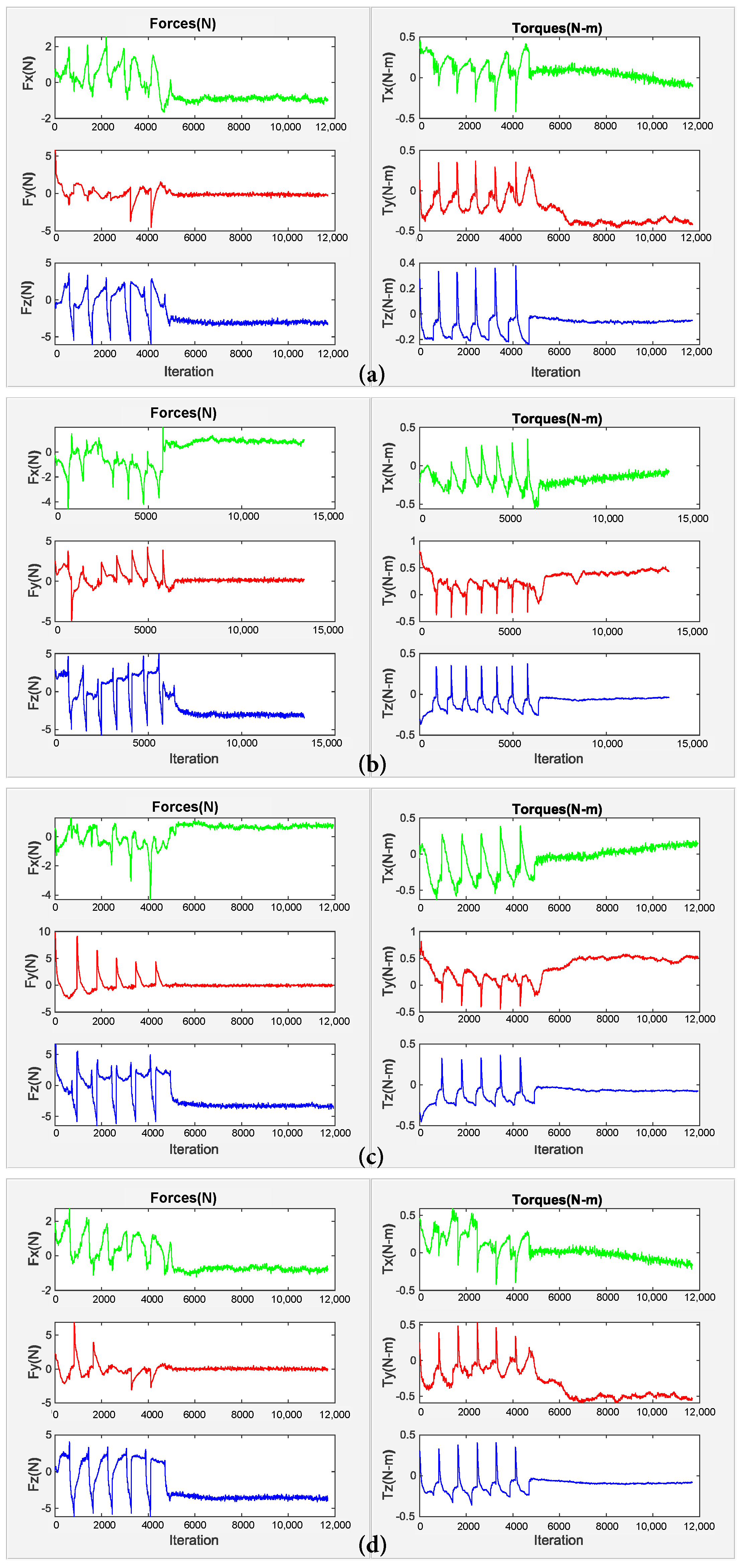
3.2. Surface Exploration

Before presenting our surface exploration schema, we refer briefly to the dynamic model of the robot with n joints, which is formulated as follows:
M ( q ) q ¨ + S ( q , q ˙ ) q ˙ + g ( q ) = τ d + τ e x t
where q , q ˙ , q ¨ and ∈ R n represent, respectively, the joint position, velocities and accelerations; M ( q ) R n × n is the inertia matrix; g ( q ) R n is the gravity vector; S ( q , q ˙ ) q ˙ = c ( q , q ˙ ) R n is the vector of Coriolis and centrifugal forces; τ d is the desired torque vector; and τ e x t is the vector of external torques. As mentioned earlier, we use the robot inbuilt joint torque sensors (The used robot (Franka) control interface allows us to read and update the robot state in real-time at a frequency of 1 kHz . It also provides a Cartesian velocity callback function along with the inbuilt Cartesian impedance of the low-level controller.). The Cartesian impedance controller to drive the robot end effector with desired system dynamics is given by the following:
Λ d e ¨ x + D d e ˙ x + K d e x = F e x t
where Λ d is a desired mass, e x is the deviation of the actual Cartesian position from the desired equilibrium point ( e ˙ x and e ¨ x are Cartesian velocities and accelerations, respectively), D d is desired damping, K d is a desired stiffness matrix and F e x t and ∈ R m are the external forces and torques at the end effector. The link between the external forces and the torques at the end effector is given by the following:
τ e x t = J ( q ) F e x t
where J ( q ) is the manipulator Jacobian matrix. Therefore, the behaviour of the robot is cast by the following closed-loop dynamics given by (8):
F τ = Λ d ( q ) x ¨ d Λ ( q ) Λ d 1 ( D d e ˙ x + K d e x ) + ( Λ ( q ) Λ d 1 I ) F e x t Λ d ( q ) J ˙ ( q ) q ˙
where F τ R m is a new control input vector, and x ¨ d is the desired Cartesian acceleration.
As stated, our tactile exploration algorithm is inspired by the gestures of visually impaired people trying to identify an object from touch. Finger probe measures the first point of intersection between a directed line and an object. Two major drawbacks of probing data are low resolution and mechanical cross talk. The latter drawback causes nonzero force reading that could be fixed by using an adaptive threshold.
The sequence of actions depicting this process is shown in Figure 4, and our overall surface exploration schema is formulated in Algorithm 1. Once the robot is positioned in the exploration task-space, i.e., after the visual servoing is converged, the control automatically switches to simultaneous exploration and data recording. Here, the robot end effector starts moving down without any feedback and stops once a rigid surface is sensed. Kinematic constraints are applied to ensure that the desired robot configuration is achievable.
During the robot exploration phase to find a nut, the rotation and translation along the Z axis are constrained to ensure that the robot can only move in the X Y plane. However, introducing hard constraints for surface exploration without any compliance might trigger motor brakes. There are strong interaction forces between the fingers and the nut during unbolting; therefore, the system requires being flexible in motion. We use active compliance along the Cartesian axes. Active compliance using impedance control plays a significant role during exploration and unbolting. While not being the major focus in this paper, compliance using adaptive stiffness might improve the flexibility of the proposed system.
As shown in Figure 4a, we assume that the bolt axis is aligned with the world Z axis, and the fingers are oriented in the same axis to ensure that only vertically planar contacts are sensed. Planar movement along the task bed is ensured by active compliance along the Cartesian axes. As shown in Figure 4b, the velocity v x is in the direction normal to the nut’s face at an angle θ 0 with respect to the robot base frame (Algorithm 1— F l a g = 0 ). As shown in Figure 4c, when the robot comes in contact with a surface and the end effector Cartesian torque goes above τ m a x , the timestamp t c o n t a c t is recorded (Algorithm 1— F l a g = 1 ). This is used to change the direction of the planar velocity at a rate k θ to a direction perpendicular to the detected surface. The gradual change in velocity leads to a decrease in the net torque experienced at the end effector. By the time the torque value drops below τ m a x , the end effector slides along the current face and comes at a position in front of the next face of the same nut (Figure 4d). This position is recorded and used as the starting point for detecting the next face of the nut (Algorithm 1— F l a g = 2 ). To avoid stray movement and to cease exploration for the current face of the nut, the velocity is decayed once the torque value goes below τ m a x . This is done by decreasing the velocities v x and v y by a factor of λ x and λ y , respectively. The magnitudes of v x and v y are given as follows:
| v x | = v m a x · sin θ + k θ · π 2 · t t c o n t a c t t m a x t c o n t a c t | v y | = v m a x · cos θ + k θ · π 2 · t t c o n t a c t t m a x t c o n t a c t
It is worth noting that the velocity profile is time-controlled to demonstrate the proof of concept. However, we refer readers to [23] for closed-loop exploration. Every end effector position ( x , y ) attained during exploration of a side of nut is added to P . Each iteration of the side exploration lasts for a duration of t m a x after which the robot position is reset to the last recorded starting point.
Algorithm 1 Surface exploration and data collection.
  • Input: t m a x , v m a x , θ 0 , x d e c a y , y d e c a y , k θ , τ m a x
  • Output: Measured data P = { ( x n , y n ) }
  •      Initialisation  θ : = θ 0 + π 3 , q : = q 0
  • 1: for i = 1 to 6 do
  • 2:     Set joint position to q , f l a g : = 0
  • 3:      θ : = θ π 3 , v x , v y : = v m a x sin θ , v m a x cos θ
  • 4:     while  t < t m a x   do
  • 5:       Append ( x , y ) of end-effector pose to P .
  • 6:        t : = t + ϵ
  • 7:       if  τ > τ m a x   then
  • 8:         if  f l a g = 0   then
  • 9:            t c o n t a c t : = t , f l a g : = 1
  • 10:         end if
  • 11:         Change the direction of velocity using (9).
  • 12:       else if  | v x | + | v y | > 0.001 then
  • 13:         if  f l a g = 1   then
  • 14:           Record q , f l a g : = 2
  • 15:         end if
  • 16:          v x , v y   : =   λ x v x , λ y v y
  • 17:       end if
  • 18:     end while
  • 19: end for
  • 20: return  P

3.3. Contact Modelling

Once the tactile exploration is completed, the contour profile of the nut is extracted by uniformly sampling hypotrochoid approximation of a regular hexagon. This sample is fitted to P , using the scaled iterative closest point (SICP) technique. The parametric equations of a general hypotrochoid function h ( ϕ ) are given in (10).
x = h 1 ( ϕ ) = ( a b ) · cos ϕ + d · cos a b b ϕ y = h 2 ( ϕ ) = ( a b ) · sin ϕ d · sin a b b ϕ
A hexagon can be approximated by setting the values of a, b and d to 6, 1 and 0.25 , respectively. These values are calculated empirically. The source point cloud M R m is then generated by uniformly sampling | P | (generated from Algorithm 1) number of data points from the above model. The SICP algorithm is applied between M = Δ { m i } i = 1 N m and P = Δ { p i } i = 1 N p , which gives a transformation matrix T . The iterative closest point methods work by iteratively registering two point sets in a same scale by minimizing an objective function related to the congruent distance. The optimisation function used in this work is given by (11) [24].
min S , R , t , j { 1 , 2 , , N m } i = 1 N p ( RS p i + t ) m j 2 2
where S = diag ( s 1 , s 2 , , s n ) is a scale matrix with a boundary, which is removed from T by normalizing its first three columns. t R m is a translation vector, and R R m × m is a rotation matrix. Solving (11) is not the focus of this paper. A full solution can be found in [24].

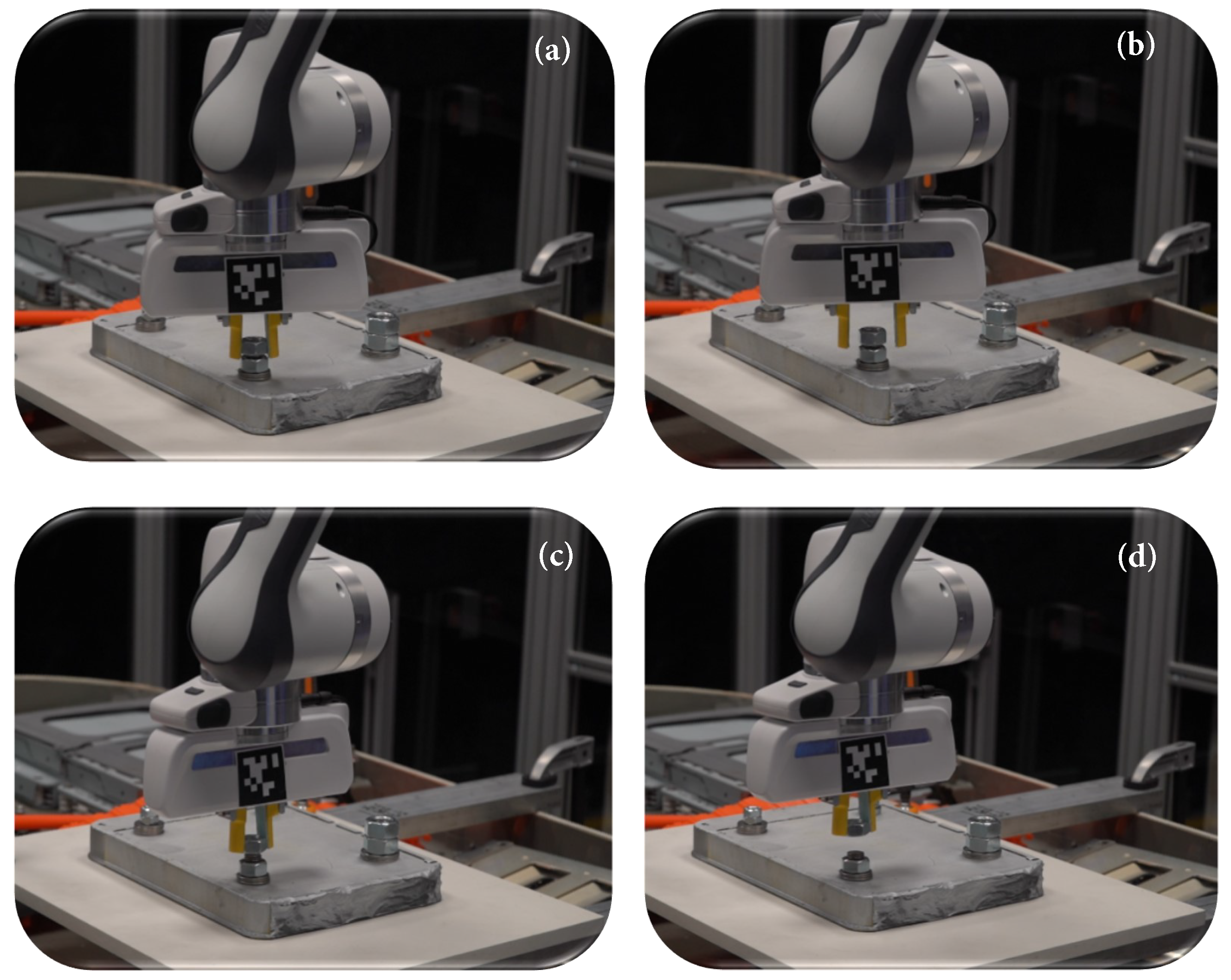
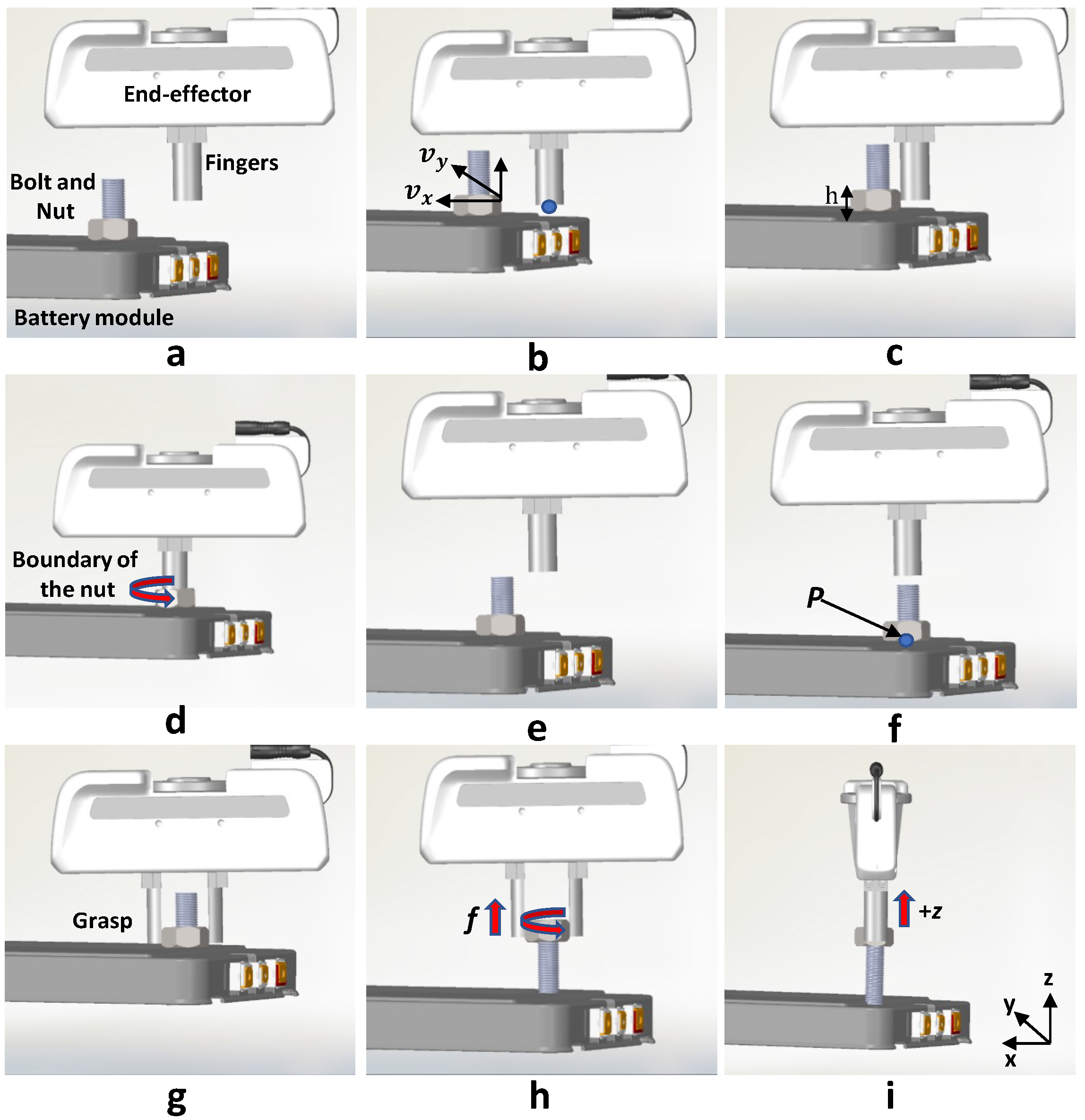
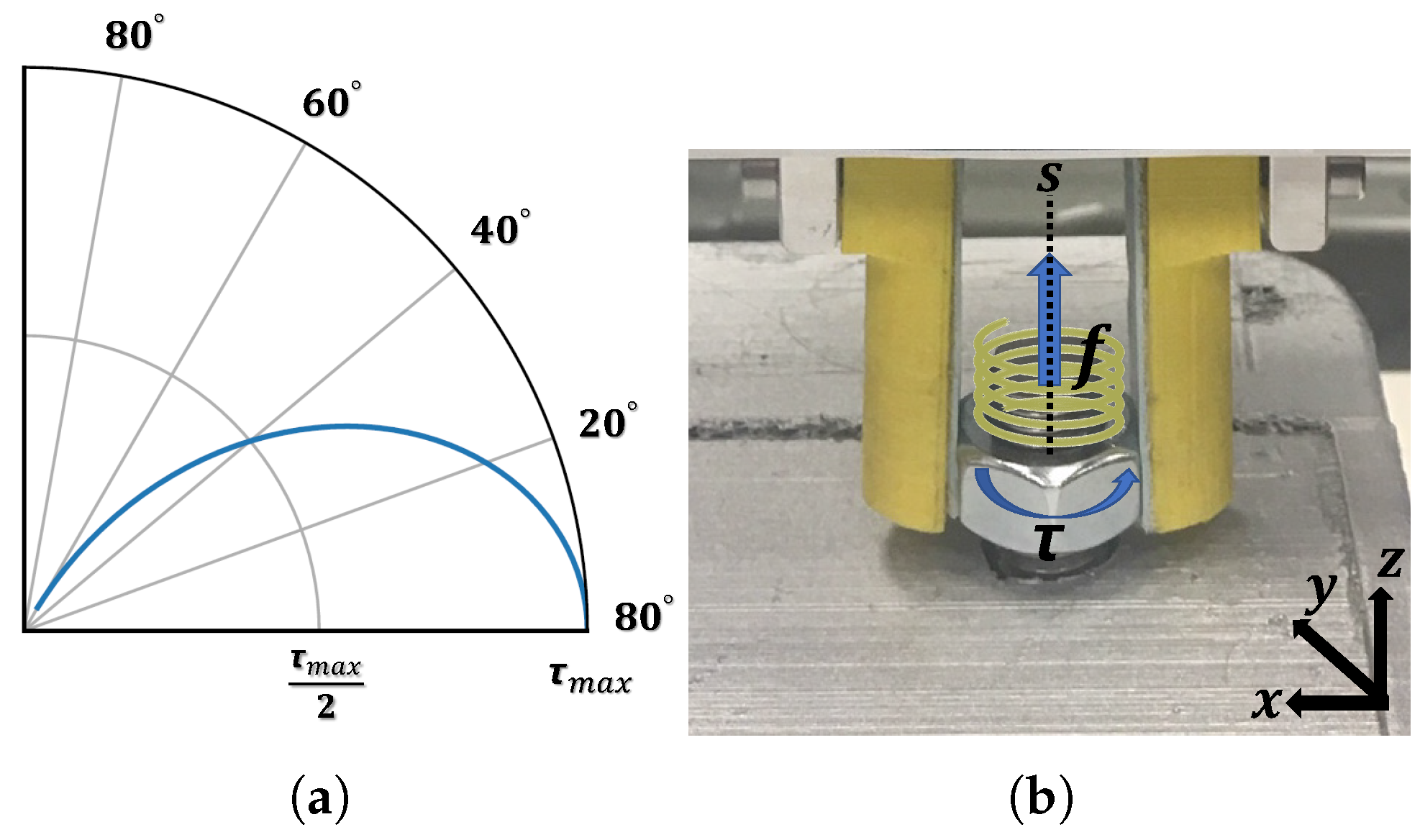
3.4. Nut Unfastening

Once the contact data are modelled, the unfastening process (summarised in Algorithm 2) starts automatically. As seen in Figure 4f, the fingers are moved to a start position, which is at an offset in the Z-axis centred at the circle identified in the previous step. This is to ensure that the nut is centred within the gripper fingers when grasped. Now, the fingers are opened and the hand starts moving down. Similar to before, it stops moving when rigid body contact is sensed. At this point, the fingers are closed to hold the nut. For placing the fingers aligned with parallel faces of the nut, the hand is oriented based on the transformation T before moving down (Figure 4g). The inverse kinematics incorporating manipulator nullspace is used for motion trajectory. Once the nut is grasped, a predefined torque trajectory as shown in Figure 5 is executed for unfastening the nut. During this trajectory, as shown in Figure 4g–i, the following three motions are executed iteratively until the nut is fully removed: (i) the end effector of the robot is rotated θ = π / 3 ; (ii) the robot releases its grasp and the gripper opens; and (iii) the tool is rotated back θ to the initial position. Throughout the trajectory, the controller applies a constant force in the + Z direction to check if the nut has disengaged from the bolt’s threads (Algorithm 2— F l a g = 1 ), as seen in Figure 4i. It is worth noting that the starting torque τ m a x in the trajectory is set to be of the order of torsional strength of the nut. This is done to handle nuts tightened to different degrees. In this work, we do not consider such cases as damaged or stuck nuts, which are handled by ad hoc procedures, e.g., via milling or drilling.
Algorithm 2 Gripping and nut unfastening.
  • Input: Measured ( x , y ) data P , ϵ q ˙
  • Output: Number of turns ( n )
  •      Initialisation : f l a g   =   0 , n   =   0
  • 1: Fit a circle C to P using Pratt’s Method [25].
  • 2: Move the gripper to center of C i.e., ( x c , y c ) .
  • 3: T   = SICP ( P , M )
  • 4: Obtain angle θ to rotate along the z-axis from T .
  • 5: while  f l a g   =   0   do
  • 6:      n   =   n + 1
  • 7:     Orient the gripper by angle θ and grasp the nut.
  • 8:     Unbolt the nut using the torque trajectory in Figure 5a.
  • 9:     Apply constant force in + z direction.
  • 10:     if  q ˙   >   ϵ q ˙   then
  • 11:        f l a g   =   1
  • 12:     end if
  • 13:     Release bolt and perform gripper homing.
  • 14: end while
  • 15: return  n

4. Experimental Evaluations

We perform a series of experiments in order to quantitatively evaluate the efficacy of the proposed framework, while joint torque feedback of the cobot is used to map the geometry of the nut. We first evaluate the shape exploration performance of our approach and later validate the unfastening performance. Although there are some methods available in the literature using motorised screwdrivers, we are unable to compare our approach with them mainly due to the lack of generality to the nut sizes. Nevertheless, the majority of these conventional state-of-the-art methods require additional hardware such as mechanical tool changers or manual intervention, which is deemed unsafe in the context of this work.

4.1. Experimental Setup

The experimental set-up designed for this study is shown in Figure 6. It consists of a 7DoF collaborative robot (FRANKA EMIKA Panda) fitted with a parallel-jaw gripper. A Logitech camera mounted in the scene is used for visual servoing, i.e., to track both robot and object markers. For the sake of smooth exploration and unfastening, we use custom-designed 3D-printed fingers. These are semi-cylindrical, where the outer curved side is used for exploration and the inner flat surface is used for gripping and unfastening the nut, as shown in Figure 1. The diameter of the finger’s cross section is 25 mm and the height of the finger is 45 mm . The fingers’ flat sides are fixed with a thin rubber pad to increase friction during the grasp. The maximum gripper stroke is 80 mm with a homing speed of 50 mm / s , which is sufficient for grasping the nuts used in this work. The software is developed in C++ and executed on a Linux machine with 32 GB RAM and an i7 CPU with a frequency of 4 GHz. The robot control programs are developed using LibFranka API, and visual marker tracking is accomplished using ViSP [26].
To emulate the real recycling setup, we use a 3D-printed cell module firmly attached to the dismantled Nissan Leaf EV battery pack. In real scenarios, inside the battery pack, a set of these modules are attached together as a stack with four long threaded bars. Replicating this with our test-bed, we use four threaded bars attached with hex nuts of varying sizes: M10, M12, M16 and M20. Although the nuts are of the same size in a real battery pack, we use a combination of them to validate our approach. The specifications of the used nuts are summarised in Table 1.

4.2. Shape Exploration Analysis

These initial experiments are conducted to evaluate the method’s performance in exploring and identifying the nuts. Succeeding the initialisation phase, the robot starts the surface exploration with constant velocities v x and v y to move in the X Y plane. The Cartesian impedance values on all axes for the robot are set to K d = ( 450 , 450 , 600 , 200 , 200 , 200 ) , which are selected empirically. A greater value is used for the stiffness in the z-axis to compensate for the gravity and weight of the gripper. The bolt placements in the test rig is shown in Figure 6, and the robot moving from initial position to the exploration position is shown in Figure 7. The end effector position and the external wrench are recorded during the tactile exploration task. Figure 8 outlines the successful trials in exploring the contour profile of four different nuts, using our method. Once contact is established between the finger and the nut, the velocities in X and Y axes are sequentially increased until the external torque ( τ e x t ) exceeds the threshold on the nut’s edges. Although the used robot benefits from relatively high accuracy torque sensors with a resolution of <0.02 Nm and a torque noise (root mean square) of <0.055 Nm, relying solely on the probing pose is not feasible to find a robust grasp. Hence, SICP is used to find the appropriate transformation to align the gripper fingers with the parallel nut faces. The final column in the figure shows the positional data recorded during the exploration and the corresponding fitted hexagons, using SICP.
The results depicted in Figure 8 suggest that the accuracy of the contact exploration pose is influenced by the size of the probe (gripper fingers in closed position) and the assigned stiffness behaviour of the control system. Averaged errors between the actual nut’s diameter and the measured one for M10, M12, M16 and M20 over 10 trials are ( 4.3 ± 0.18 mm ), ( 3.2 ± 0.19 mm ), ( 2.3 ± 0.2 mm ) and ( 3.8 ± 0.1 mm ), respectively. We believe that these errors are mainly due to the impedance behaviour, as the Z-axis of the end effector is not always orthogonal to the norm vector of the nut’s side plane during exploration. There is no linear correlation between the size of the fingers and the error. However, we believe increasing the rigidity of the probe would improve exploration accuracy.
The wrench data show a breakdown procedure for determining the hexagonal pattern of the nuts during exploration. The peak points in F = ( f x , f y , f z ) show the turning points on the nut edges. The sign of the forces ( f x , f y ) changes on the turning points with respect to the direction of the applied velocity. Although the end effector continues to move along the contacted side due to the applied velocities ( v x , v y ), a high amplitude torque ( τ > τ m a x ) indicates the turning point. Therefore, the end effector returns to the most recent torque pick point and originates its movement by adjusting the velocity with respect to the turning angle θ . On the turning points, when there is a high amplitude force in X-axis, a lower amplitude force in the Y-axis is appeared. A similar trend is observed for all four nuts during contact exploration. The plateau state between the peak points, for both forces and torques, indicates that the probe is not in contact with the nut at that particular point of time.

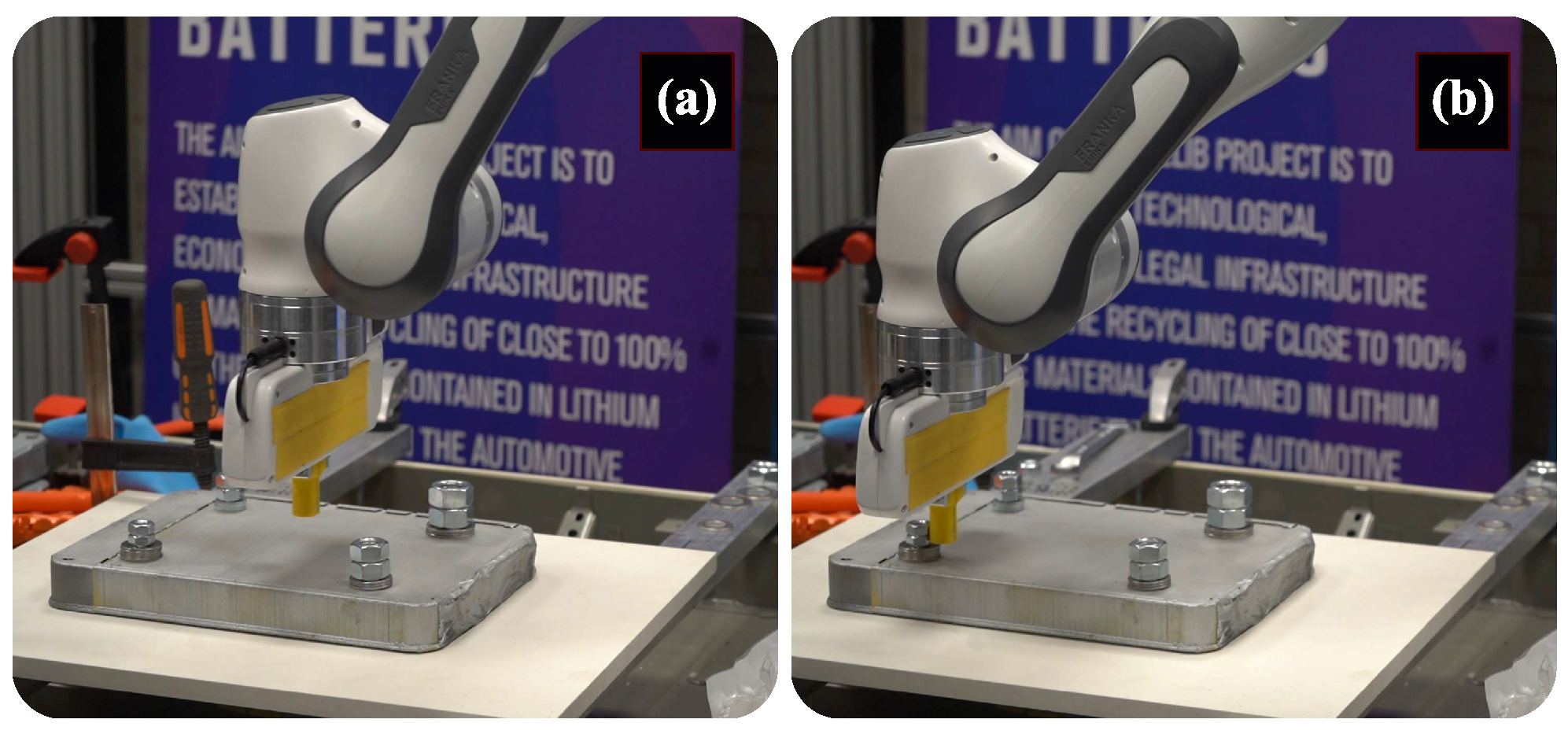
4.3. Unfastening Analysis

Once the exploration is accomplished, unfastening starts automatically (Figure 9). It is initialised by opening the gripper to its maximum stroke size. The two outputs from the previous exploration phase are (i) the location of the nut, i.e., its centre point pose with respect to the robot base frame; and (ii) parallel faces of the nut to position gripper fingers. The poses of these estimated nut faces are used to orient the gripper fingers, and a pinch grasp is executed to hold the nut. Alternatively, a model-free grasp planner, like that in [27], can also be used to plan a stable grasp trajectory.
To evaluate the performance of the robot, wrench screws that encapsulate valuable information about the dynamic behaviour of the robot are studied. The estimated external wrenches (f, τ ) are expressed with respect to the stiffness frame. Figure 10 shows the successful unbolting trials for all four nuts. It is worth noting that the thread count and pitch sizes are different for each nut, and this information is not known a priori. Moreover, in contrast to many state-of-the-art methods, our approach is independent of this information and stops the unfastening process based on the online perceived information. In the figure, the number of peak points with the highest amplitude illustrates the number of turns n, which is shown by f z and z .
The force and torque trends illustrate that the forces and torques are varied considerably when ( | | q ˙ | | < ϵ q ˙ ) , i.e., while the robot is executing consequent motions to unfasten. It can be noticed that the forces are stabilised when the nut is disengaged from the threaded bar. Upon removal of the nut, we see that the forces in Y-axis are declined to zero and remain constant, while the forces in the X and Y directions remain on the negative side. The negative plateau trend of these forces in X and Z can be interpreted by the stiffness behaviour of the impedance controller. Looking at the torque signals, it shows that the torque values vary between 0.9 τ 0.9 , as τ m a x = 0.9 Nm is manually set for the controller. The applied torque is relatively low, as the nut is not tightened very hard. This is done to demonstrate the proof of concept and mainly to avoid exceeding the robot joint torque limits. Alternatively, this can be handled up to an extent by using an adaptive gain for the torque.

4.4. Discussion

The entire process of unbolting is repeated over ten trials, and the number of failures, reasons of failure and the averaged time of task completion are mentioned in Table 2. The following conditions are treated as failures:
(a)
Failure due to size of the probing tool;
(b)
Hardware failure (reflex errors). It happens when the estimated external torques or forces exceed the limits;
(c)
Missing a side of the nut during exploration;
(d)
Coarse pose calculation, due to the impedance;
(e)
Jammed nut.
On average, it takes 9 s for the visual servoing to converge, i.e., to bring the tool to the exploration space. From the results in Table 2, our system achieved 100 % success with the M20 sized nut with the average time to explore and unfasten being 50 s each. Since the pitch sizes are different, and the number of turns is not the same during unfastening, interpreting the task completion time is trivial. However, the number of turns for the overall task is between 5 and 10 turns (over 10 trials), which may provide a ballpark figure to the reader about the execution time.
Next, with a reduction in the size of the nut, the total number of exploration failures is increased. From the analysis, we see that the majority of failures are due to the size of the custom designed exploration probe (thickness and diameter). This can be verified by the fact that the maximum number of failures occurred for the smallest nut—M10. For the M16 nut, the exploration failed once due to a hardware reflex error, in which case the robot controller triggers emergency brakes, suspecting a collision. Further to the aforementioned failures during exploration, we also observed that the end effector started sliding on the nut’s face but did not follow the condition ( τ > τ m a x ) . This made it fail to return to the most recent torque pick point and consequently missed exploring the next face. This failure happened because of the size and low rigidity of the probe, and the noisy torque signals τ e x t measured by the controller. It is worth mentioning that, by default, the used robot controller runs a low-pass filter with a 100 Hz cutoff frequency to filter the measured signals.
Furthermore, it was observed that the nut M10 was jammed during two unfastening trials, and consequently failed the tasks. Nut jamming happened in the last turn, where the nut was on the last thread and only one turn was required to lift the nut along the screw axis. At this point, the nut was not constrained by the thread, and the axial of the threaded bar was not coincident with the axial of the nut. Therefore, the nut was tilted slightly, and it jammed. The proposed framework could be scaled well to small screws, but with the current setup, it might be infeasible, as the noise will likely be higher than the useful torque signal acquired during exploration.

5. Conclusions

In this paper, we presented a primary attempt to automate the task of nut unfastening by means of robotic surface exploration. Our method solely depends on the self-contained proprioception of the robot, and eliminates the need for external expensive hardware. We have demonstrated this in the context of dismantling an EV battery pack, where individual cell modules are to be separated from their stack. The proposed method benefits from the amalgamation of visual servoing, tactile perception, using the probing technique, and unbolting based on joint force/torque feedback. Visual servoing assisted the robot in moving its end effector into the task space, while the probing technique allowed the robot to explore the contour profile of the nut. The output of tactile mapping provided the required information for the robot to align its end effector and perform a robust grasp. The presented system was evaluated on a mock-up, emulating a real recycle system, by conducting experiments on unfastening four different-sized nuts. The obtained results suggest a success rate of 95 % in exploration and unbolting tasks, respectively.
To the best of our knowledge, only a handful of works have tried to automate the EV battery dismantling process by combining visual feedback with torque controllers in a discrete fashion to accomplish (un-)fastening with automated nut-runners. In this perspective, in future, we plan to integrate visual feedback with surface exploration and unfastening to deal with uncertainties raised during the task execution, e.g., some of the failure causes reported in this work. In addition, we plan to follow a data-driven approach for exploration to generalise our method for a variety of screws/nuts with different shapes and sizes.

Author Contributions

Conceptualisation, A.R., R.N., R.S. and N.M.; data curation, A.R. and R.N.; formal analysis, A.R. and R.N.; funding acquisition, A.R. and N.M.; investigation, A.R. and N.M.; methodology, R.N.; project administration, A.R., R.S. and N.M.; resources, R.S.; software, R.N.; supervision, A.R., R.S. and N.M.; validation, R.N.; visualisation, R.N.; writing—original draft, A.R., R.N. and N.M.; writing—review and editing, A.R., R.N., R.S. and N.M. All authors have read and agreed to the published version of the manuscript.

Funding

This research was conducted as part of the Faraday Institution sponsored RELIB: Reuse and Recycling of Lithium-Ion Batteries project with a grant number FIRG005. It is also partly funded by CHIST-ERA under Project EP/S032428/1 PeGRoGAM.

Institutional Review Board Statement

Not applicable.

Informed Consent Statement

Not applicable.

Acknowledgments

The authors would like to thank Maxime Adjigble for his support in developing force-torque controller, Tommaso Pardi for active discussions on exploration schemes, and Christopher Gell for his technical support.

Conflicts of Interest

The authors declare no conflict of interest.

References

  1. Cazzola, P.; Gorner, M.; Schuitmaker, R.; Maroney, E. Global EV Outlook 2016; International Energy Agency: Paris, France, 2016. [Google Scholar]
  2. Jia, Z.; Bhatia, A.; Aronson, R.M.; Bourne, D.; Mason, M.T. A survey of automated threaded fastening. IEEE Trans. Autom. Sci. Eng. 2018, 16, 298–310. [Google Scholar] [CrossRef]
  3. Li, R.; Pham, D.T.; Huang, J.; Tan, Y.; Qu, M.; Wang, Y.; Kerin, M.; Jiang, K.; Su, S.; Ji, C.; et al. Unfastening of Hexagonal Headed Screws by a Collaborative Robot. IEEE Trans. Autom. Sci. Eng. 2020, 17, 1455–1468. [Google Scholar] [CrossRef]
  4. Cruz-Ramírez, S.R.; Mae, Y.; Arai, T.; Takubo, T.; Ohara, K. Vision-Based Hierarchical Recognition for Dismantling Robot Applied to Interior Renewal of Buildings. Comput.-Aided Civ. Infrastruct. Eng. 2011, 26, 336–355. [Google Scholar] [CrossRef]
  5. Gil, P.; Pomares, J.; Diaz, S.v.P.C.; Candelas, F.; Torres, F. Flexible multi-sensorial system for automatic disassembly using cooperative robots. Int. J. Comput. Integr. Manuf. 2007, 20, 757–772. [Google Scholar] [CrossRef] [Green Version]
  6. Seliger, G.; Keil, T.; Rebafka, U.; Stenzel, A. Flexible disassembly tools. In Proceedings of the 2001 IEEE International Symposium on Electronics and the Environment, 2001 IEEE ISEE (Cat. No. 01CH37190), Denver, CO, USA, 9 May 2001; pp. 30–35. [Google Scholar]
  7. Chen, W.H.; Wegener, K.; Dietrich, F. A robot assistant for unscrewing in hybrid human-robot disassembly. In Proceedings of the IEEE International Conference on Robotics and Biomimetics (ROBIO 2014), Bali, Indonesia, 5–10 December 2014; pp. 536–541. [Google Scholar]
  8. Apley, D.W.; Seliger, G.; Voit, L.; Shi, J. Diagnostics in disassembly unscrewing operations. Int. J. Flex. Manuf. Syst. 1998, 10, 111–128. [Google Scholar] [CrossRef]
  9. Zuo, B.R.; Stenzel, A.; Seliger, G. A novel disassembly tool with screwnail endeffectors. J. Intell. Manuf. 2002, 13, 157–163. [Google Scholar] [CrossRef]
  10. Wegener, K.; Chen, W.H.; Dietrich, F.; Dröder, K.; Kara, S. Robot assisted disassembly for the recycling of electric vehicle batteries. Procedia CIRP 2015, 29, 716–721. [Google Scholar] [CrossRef]
  11. Mironov, D.; Altamirano, M.; Zabihifar, H.; Liviniuk, A.; Liviniuk, V.; Tsetserukou, D. Haptics of screwing and unscrewing for its application in smart factories for disassembly. In International Conference on Human Haptic Sensing and Touch Enabled Computer Applications, Proceedings of the 11th International Conference, EuroHaptics 2018, Pisa, Italy, 13–16 June 2018; Springer: Cham, Switzerland, 2018; pp. 428–439. [Google Scholar]
  12. DiFilippo, N.M.; Jouaneh, M.K. A system combining force and vision sensing for automated screw removal on laptops. IEEE Trans. Autom. Sci. Eng. 2017, 15, 887–895. [Google Scholar] [CrossRef]
  13. Berger, E.; Grehl, S.; Vogt, D.; Jung, B.; Amor, H.B. Experience-based torque estimation for an industrial robot. In Proceedings of the IEEE International Conference on Robotics and Automation (ICRA), Stockholm, Sweden, 16–21 May 2016; pp. 144–149. [Google Scholar]
  14. Pfeiffer, K.; Escande, A.; Kheddar, A. Nut fastening with a humanoid robot. In Proceedings of the IEEE/RSJ International Conference on Intelligent Robots and Systems (IROS), Vancouver, BC, Canada, 24–28 September 2017; pp. 6142–6148. [Google Scholar]
  15. Pitipong, S.; Pornjit, P.; Watcharin, P. An automated four-DOF robot screw fastening using visual servo. In Proceedings of the IEEE/SICE International Symposium on System Integration, Sendai, Japan, 21–22 December 2010; pp. 379–383. [Google Scholar]
  16. Adams, G. Next Generation Mobile Robotic Drilling and Fastening Systems. In Proceedings of the SAE 2014 Aerospace Manufacturing and Automated Fastening Conference & Exhibition, Salt Lake City, UT, USA, 23–25 September 2014. [Google Scholar] [CrossRef] [Green Version]
  17. Hu, Z.; Wan, W.; Koyama, K.; Harada, K. A Mechanical Screwing Tool for 2-Finger Parallel Grippers—Design, Optimization, and Manipulation Policies. arXiv 2020, arXiv:2006.10366. [Google Scholar]
  18. Yokokohji, Y.; Kawai, Y.; Shibata, M.; Aiyama, Y.; Kotosaka, S.; Uemura, W.; Noda, A.; Dobashi, H.; Sakaguchi, T.; Yokoi, K. Assembly Challenge: A robot competition of the Industrial Robotics Category, World Robot Summit—Summary of the pre-competition in 2018. Adv. Robot. 2019, 33, 876–899. [Google Scholar] [CrossRef] [Green Version]
  19. Dhayagude, N.; Gao, Z.; Mrad, F. Fuzzy logic control of automated screw fastening. Robot. Comput.-Integr. Manuf. 1996, 12, 235–242. [Google Scholar] [CrossRef]
  20. Seneviratne, L.D.; Visuwan, P.; Althoefer, K. Weightless neural network based monitoring of screw fastenings. In Human and Environment Friendly Robots with High Intelligence and Emotional Quotients (Cat. No. 99CH36289), Proceedings of the 1999 IEEE/RSJ International Conference on Intelligent Robots and Systems, Kyongju, Korea, 17–21 October 1999; IEEE: Piscataway, NJ, USA, 1999; Volume 1, pp. 561–566. [Google Scholar]
  21. Chaumette, F.; Hutchinson, S. Visual Servoing and Visual Tracking. In Springer Handbook of Robotics; Christensen, H.I., Ed.; Springer: Berlin/Heidelberg, Germany, 2008; Chapter 24; pp. 563–583. [Google Scholar]
  22. Siciliano, B.; Sciavicco, L.; Villani, L.; Oriolo, G. Robotics: Modelling, Planning and Control; Springer Science & Business Media: Berlin/Heidelberg, Germany, 2010. [Google Scholar]
  23. Li, Q.; Schurmann, C.; Haschke, R.; Ritter, H. A Control Framework for Tactile Servoing. In Robotics: Science and Systems; Citeseer: Princeton, NJ, USA, 2013. [Google Scholar] [CrossRef]
  24. Du, S.; Zheng, N.; Xiong, L.; Ying, S.; Xue, J. Scaling iterative closest point algorithm for registration of m–D point sets. J. Vis. Commun. Image Represent. 2010, 21, 442–452. [Google Scholar] [CrossRef]
  25. Pratt, V. Direct Least-squares Fitting of Algebraic Surfaces. SIGGRAPH Comput. Graph. 1987, 21, 145–152. [Google Scholar] [CrossRef]
  26. Marchand, É.; Spindler, F.; Chaumette, F. ViSP for visual servoing: A generic software platform with a wide class of robot control skills. IEEE Robot. Autom. Mag. 2005, 12, 40–52. [Google Scholar] [CrossRef] [Green Version]
  27. Adjigble, M.; Marturi, N.; Ortenzi, V.; Rajasekaran, V.; Corke, P.; Stolkin, R. Model-free and learning-free grasping by local contact moment matching. In Proceedings of the IEEE/RSJ International Conference on Intelligent Robots and Systems (IROS), Madrid, Spain, 1–5 October 2018; pp. 2933–2940. [Google Scholar]
Figure 1. Robotic unfastening of a hexagonal bolt using our proposed method. Based on the explored information, gripper fingers are positioned to make repetitive motions to unfasten the nut.
Robotics 10 00107 g001
Figure 2. Illustration of the proposed framework pipeline. It consists of four main components, which are responsible for task initialisation by positioning the robot in task space (using Visual Servoing), object surface exploration and data recording (by monitoring the torque data), contact modelling from the recorded data (by hypotrochoid approximation) and executes the task by iteratively rotating the robot hand.
Robotics 10 00107 g002
Figure 3. (top) Some screenshots showing our visual servoing process by which the tool is placed in the task space to start surface exploration. (Bottom) Joint velocity and pose error plots depicting the visual servoing convergence.
Robotics 10 00107 g003
Figure 4. Schematic view of the sequence of actions showing our (ad) exploration and (ei) unfastening process. During exploration, our system records the positional data based on the tactile information, and during unfastening, these data are used to identify the position of the nut and its faces for grasping the nut. Thereafter, a series of rotations are made to fully unfasten the nut.
Robotics 10 00107 g004
Figure 5. Unbolting: (a) the trajectory used for unbolting; (b) schematic view of wrench screw acting on a rigid body.
Robotics 10 00107 g005
Figure 6. Experimental setup for nut unfastening. Replicating the real setup, a 3D-printed lithium–ion module is bolted onto a dismantled Nissan Leaf 2012 battery pack. The robot arm is equipped with a two-finger gripper.
Robotics 10 00107 g006
Figure 7. (a) The initial position for the exploration task, which is also the desired position for the previous visual servoing task. (b) Robot starting to explore a M10 sized nut. Detailed results can be seen in the video abstract.
Robotics 10 00107 g007
Figure 8. Estimated external wrench during contact exploration for (a) M10, (b) M12, (c) M16, and (d) M20. The first, second and third columns depict the external forces, external torques and the end effector position, respectively.
Robotics 10 00107 g008
Figure 9. Illustration of our unfastening process, where the robot, after grasping the nut, makes a series of repetitive motions until the unbolting force condition is met, i.e., the nut is fully disengaged from its bolt. (a) The nut is grasped and the end effector is rotated θ around its axial; (b) the gripper is fully opened, moved in θ and then (a) is repeated; (c) a constant force is applied in the +z direction to check if the nut is disengaged; (d) the nut is removed. Detailed results can be seen in video abstract.
Robotics 10 00107 g009
Figure 10. Estimated external wrench during unbolting task for (a) M10, (b) M12, (c) M16, and (d) M20. The first and second columns illustrate the estimated external forces and estimated external torques, respectively.
Robotics 10 00107 g010
Table 1. Geometric properties of the used test nuts.
Bolt ModelOuter Diameter
(mm)
Side Width
(mm)
Side Height
(mm)
Weight (kg)
M1019980.011
M122111100.017
M16271412.50.030
M20331715.50.061
Table 2. Repeatability test for tactile exploration and unbolting.
NutNumber of Failures 1Failure CausesAvg. Time 2 (s)
ExploreUnfastenExploreUnfastenExploreUnfasten
M2000N/AN/A4654
M1610a, bN/A4254
M1220a, dN/A3853
M1032a, b, ce3752
1 Averaged out of 10 trials. 2 Averaged time of successful trials.
Publisher’s Note: MDPI stays neutral with regard to jurisdictional claims in published maps and institutional affiliations.

