Article

A Laser-Based Direct Cable Length Measurement Sensor for CDPRs

1
Robot and Assistive Systems Department, Fraunhofer Institute for Manufacturing Engineering and Automation IPA, Nobelstrasse 12, D-70569 Stuttgart, Germany
2
Institute for Control Engineering of Machine Tools and Manufacturing Units (ISW), University of Stuttgart, Seidenstrasse 36, D-70174 Stuttgart, Germany
*
Author to whom correspondence should be addressed.
Robotics 2021, 10(2), 60; https://doi.org/10.3390/robotics10020060
Submission received: 5 March 2021 / Revised: 9 April 2021 / Accepted: 13 April 2021 / Published: 21 April 2021
(This article belongs to the Section Sensors and Control in Robotics)

Abstract

:
Accuracy improvement is an important research topic in the field of cable-driven parallel robots (CDPRs). One reason for inaccuracies of CDPRs are deviations in the cable lengths. Such deviations can be caused by the elongation of the cable due to its elasticity or creep behavior. For most common CDPRs, the cable lengths are controlled using motor encoders of the winches, without feedback about the actual elongation of the cables. To address this problem, this paper proposes a direct cable length measurement sensor based on a laser distance sensor. We present the mechanical design, the first prototype and an experimental evaluation. As a result, the measurement principle works well and the accuracy of the measured cable lengths is within −2.32 mm to +1.86 mm compared to a range from −5.19 mm to +6.02 mm of the cable length set with the motor encoders. The standard deviation of the cable length error of the direct cable length measurement sensor is 58% lower compared to the one set with the motor encoders. Equipping all cables of the cable robot with direct cable length measurement sensors results in the possibility to correct cable length deviations and thus increase the accuracy of CDPRs. Furthermore, it enables new possibilities like the automatic recalibration of the home pose.

1. Introduction

Cable-driven parallel robots (CDPRs) are a subclass of parallel robots. Instead of rigid links, CDPRs consist of cables, which connect a moving mobile platform with the cable robot frame. By changing the cable lengths, the mobile platform can be moved. Advantageous properties of CDPRs are their large workspace, scalability, high payloads and high dynamics.
Most industrial applications, such as 3D-printing, pick and place, or assembly tasks, require a high accuracy of the robot. Meeting the required accuracy for industrial applications can be critical for CDPRs [1]. Therefore, accuracy improvement is an important field of research of CDPRs [2,3]. The accuracy of CDPRs is influenced by various effects:
-
Cable properties (elasticity, creep, hysteresis, cable wear, ...);
-
Mechanical components: CDPR-frame, platform, pulleys, drive trains (manufacturing accuracy, mechanical play, motor/encoder resolution, stiffness, friction, ...);
-
Winch properties (cable flattening, coiling errors, non-linear cable length to drive ratio, ...);
-
Accuracy of the calibration;
-
Geometric and kinematic models used in the controller (cable sagging caused by cable mass, pulley kinematic, deflection due to external forces, ...).
A detailed list can also be found in [4] (p. 26).
Among these effects, cable elasticity is one of the major factors influencing the accuracy of CDPRs, especially of CDPRs with plastic fiber cables [2]. Furthermore, regarding long-term accuracy, cable creep is an important issue. Cable creep especially appears using synthetic fiber cables, which are often used for CDPRs because of their low inertia and thus good dynamics. Over a longer period of time, the cables elongate because of the constant load of the platform. Thus, the offset of the relation between encoder values and cable length changes, which leads to an accuracy error.
Most CDPR-controllers are based on the assumption that cables are inelastic and straight lines. An inverse kinematic code translates a given pose into cable length and then into encoder values, which are sent to the winches. The encoders measure the rotation of the drum onto which the cable is coiled, as for example on the IPAnema [5] or CoGiRo [6]. The main practical problem is the difficulty measuring the actual distance between the platform and the frame as the winch-integrated measurement cannot capture the influence of creep, sagging, elasticity, coiling errors, flattening, or non-linear cable length to drive ratios on the cable length. This eventually leads to pose errors.
One method used to compensate for errors caused by cable creep is a frequent recalibration of the home pose to correct the offset of the relation between encoder values and cable length. Approaches to calibrate CDPRs are presented in [7] and even automated in [8]. Both methods need measurement input at different poses in the workspace. In [7], this input comes from a laser tracker, in [8] from the internal position and cable force sensors. This requires to move the robot for calibration, which is not always possible depending on the application. A mathematical approach to model cable creep can be found in [9]. However, due to the non-linearity and variety of influencing factors, accurate models for cable creep are challenging.
There are two possibilities to address the elongation error due to cable elasticity. The first one is to model cable elongation effects mathematically. In [2], a simple elongation model is developed, implemented, and tested on the IPAnema 3 cable robot which results in an accuracy increase of the average error of almost 40%. The method calculates a cable force distribution at the actual pose. The external forces applied on the platform (the external wrench) are considered to be constant. Any additional external force leads to errors. The cable force distribution algorithm could be changed to consider a changing wrench, but this would require knowledge of the external forces such as the weight of a handled object. In [1], elasticity, including cable sagging, is considered in the inverse kinematic model. Furthermore, visual servoing is used for pose estimation. This leads to the second possibility: the compensation of cable elasticity and creep effects with feedback from additional external sensors. This feedback can come from cameras like in [1,10] which requires the platform to be always visible for the camera. In [11], angular sensors at the proximal anchor points of a CDPR are proposed and a simulation evaluating the accuracy improvement is presented. An experimental evaluation is not included. In [12], a similar approach with cable orientation sensors for a CDPR with two and three cables is presented. With regard to accuracy improvement, it is stated that especially for large-scale CDPRs, the cable orientation must be very accurate. Extending the principle for cable robots with more than three cables is part of future research.
Two different approaches to get feedback about the real cable length can be found in [3,13,14]. They present a method to directly measure the cable length with different measurement principles. In [3,13], the idea is to use a hall sensor and small strips of magnetic tape attached to the cable in a known distance or, also in [3], to use colored marks which can be detected by an IR optical sensor. In [14], the method with colored marks has been further elaborated. However, to get the initial cable length (calibration of the home pose), this method requires moving the robot. In this paper’s example, the required movement of the cable in average accounts for 0.622 m. The resolution depends on the length of the cable, the number of the color sensors used, and the distance of the color sensors and marks. In the given examples, the best resolution for a cable of 60 m is 0.1 m, with 84 marks on the cable and 15 color sensors.
The use of friction pulleys for direct cable length measurement is another suggestion which can be found in [15] (p. 362). However, aside from the idea itself, to the best of the authors’ knowledge, no further investigation of this idea can be found in the literature.
This paper presents a new device to measure the cable length directly, based on a laser distance sensor. More precisely, the cable length of the standard pulley kinematic, assuming cables as straight lines and thus the geometrical length is determined. The measured feedback cable length is a first step towards the correction of cable length inaccuracies due to cable elasticity or creep. Thus, the accuracy of CDPRs can be improved.
The paper is structured as follows: In Section 2, the concept, kinematic, an analysis of the measurement error due to cable sagging, and the mechanical design of the direct cable length measurement sensor are explained. In Section 3, the direct cable length measurement sensors are experimentally evaluated and the results are discussed. Finally, the paper closes with a conclusion and outlook.

2. Approach: Direct Cable Length Measurement Sensor

A schematic sketch of the approach of the direct cable length measurement sensor (in the following named DCLM-Sensor) is shown in Figure 1.
The kinematic of the DCLM-Sensor and the CDPR can be brought in relation to each other with the points A, B and C. According to the standard kinematic model in [15], A and B are the proximal and distal anchor points of the cable, located on the frame of the CDPR and mobile platform, respectively. The point C is defined as the point where the cable leaves the pulley [16].
The idea of the DCLM-Sensor is to determine the effective cable length between the points A and B more accurately than with the encoder values of the winch. To accomplish this, a mechanical structure is mounted on the pulley that can rotate around its axis. A laser distance sensor is mounted on this structure. A guiding unit ensures that the laser distance sensor is aligned parallel with the direction of the cable. On the other end of the cable, at the cable-platform connector B, a reflector for the laser beam is mounted perpendicularly to the cable direction.

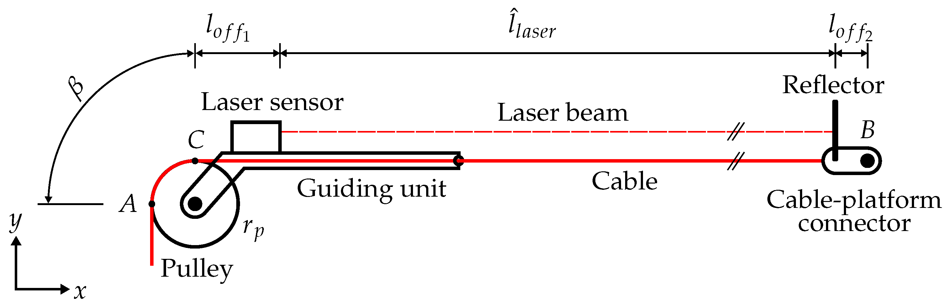
2.1. Kinematic of the DCLM-Sensor

The kinematic of the DCLM-Sensor is explained in Figure 1. It is assumed that the laser beam is parallel to the cable. To obtain the cable length l ^ from the length measured by the laser l ^ l a s e r , the following lengths have to be added. First, the offsets l o f f 1 , l o f f 2 and second the length of the cable, which is wrapped around the pulley between the points A and C, named l AC . The offsets l o f f 1 and l o f f 2 are determined as constant values during the calibration of the home pose of the cable robot. The length l A C = β r p , with the pulley radius r p and the angle β between point A and C, depends on the actual pose of the platform. It can be calculated according to the inverse pulley kinematic presented in [16]. Thus, the cable length l ^ is defined as follows:
l ^ = β r p + l o f f 1 + l ^ l a s e r + l o f f 2

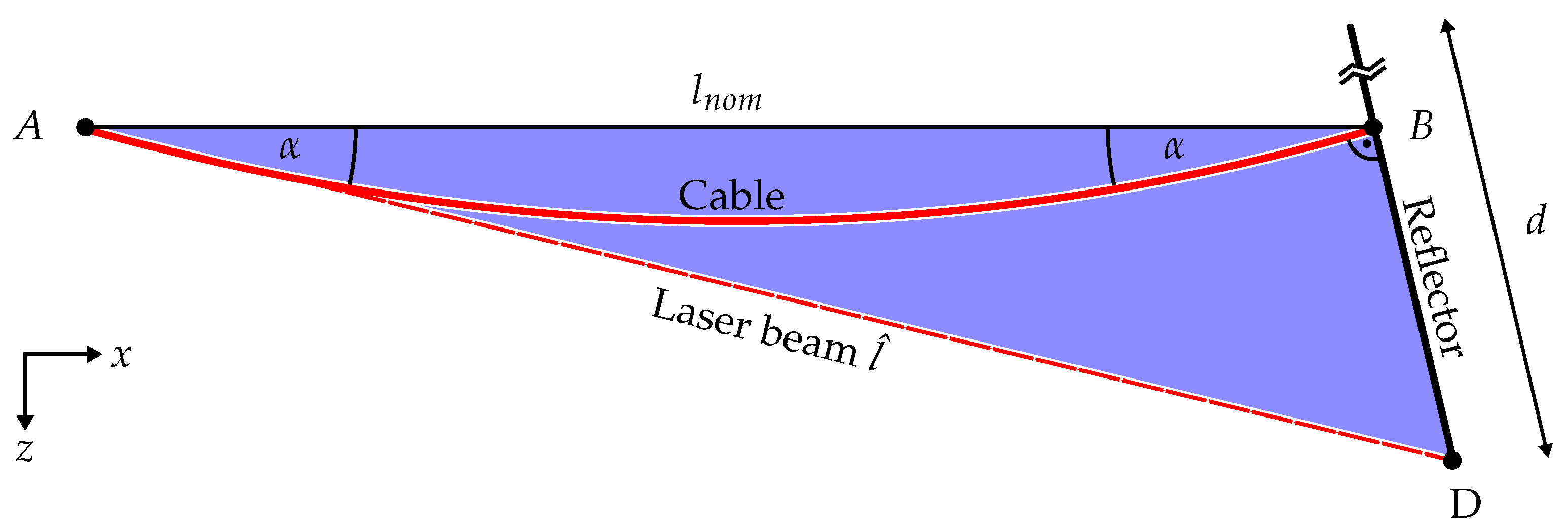
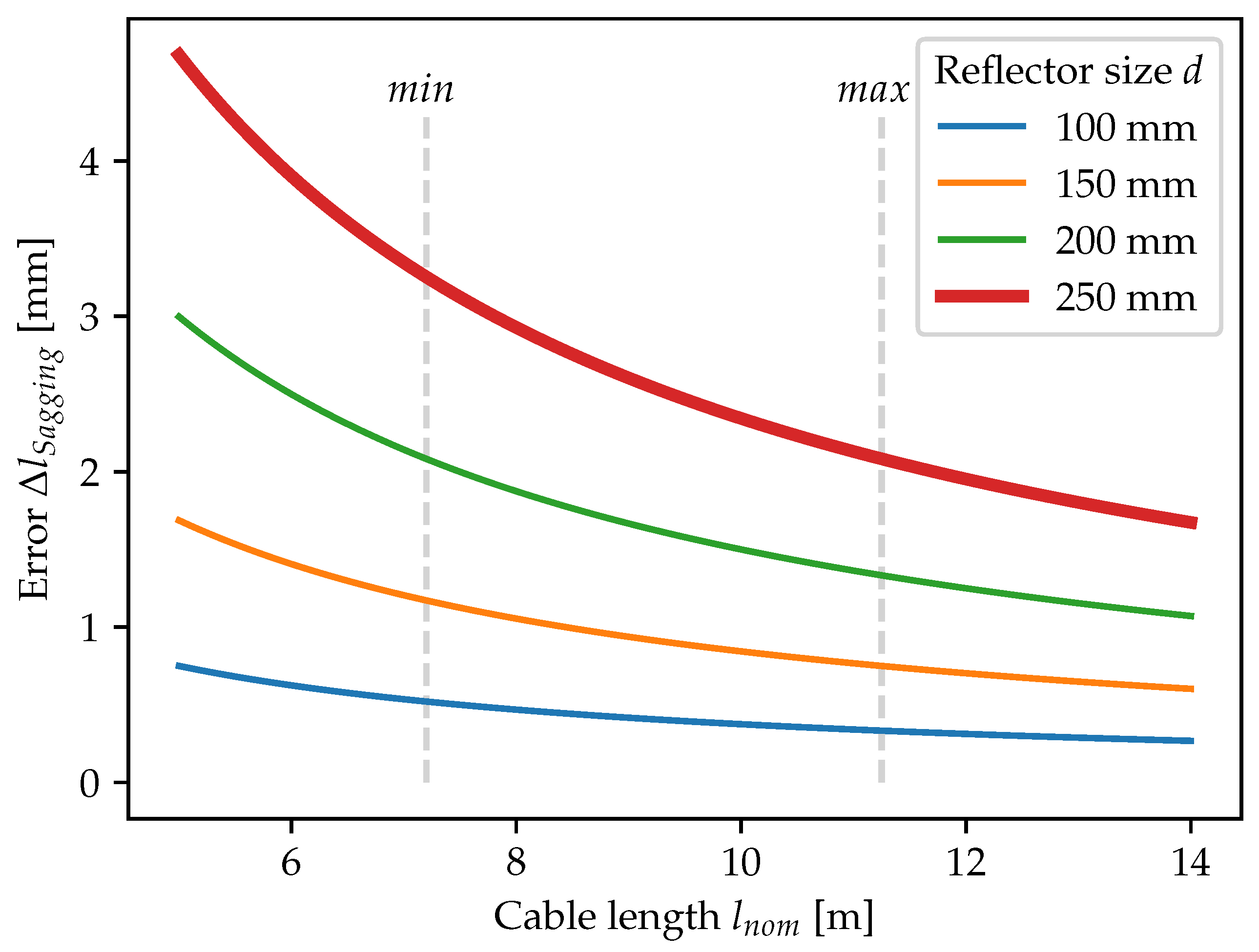
2.2. Measurement Error Due to Cable Sagging

One possible source of inaccuracies of the DCLM-Sensor is the misalignment of the laser beam and the cable, which can be caused by cable sagging. In the following, a worst-case scenario is analyzed in theory. For the analysis, the following assumptions are made: the cable is oriented horizontally and the cable sags symmetrically. This worst-case scenario is depicted in Figure 2.
The straight distance between the proximal anchor point A and the distal anchor point B is named l n o m , the relevant size of the reflector is denoted with d. The angle between the straight connection line of A and B, and the sagging cable is α . The worst-case α is the angle where the laser beam of the DCLM-Sensor hits the boarder of the reflector. Regarding the blue triangle, we receive the following formula with the sine theorem for the worst-case α :
l n o m sin ( α ) = d 2 cos ( 2 α )
Solving Equation (2) for the worst-case α = α w o r s t - c a s e , we can calculate the cable length l ^ measured by the DCLM-Sensor:
l ^ = l n o m cos ( α w o r s t - c a s e ) cos ( 2 α w o r s t - c a s e )
With the cable length measured by the DCLM-Sensor with worst-case sagging and the nominal cable length l n o m , the cable length error due to sagging Δ l S a g g i n g can be calculated:
Δ l S a g g i n g = l ^ l n o m
The result of the cable length error Δ l S a g g i n g is plotted over the nominal cable length l n o m in Figure 3. The error of the reflector size used in this paper, d = 250 mm, is depicted with a bold red line. Additionally, the error for smaller reflectors with a size of 100 mm, 150 mm, and 200 mm is added in blue, yellow, and green, respectively. These additional lines also display the error for smaller alignment errors ( α < α w o r s t - c a s e ). Furthermore, in Figure 3, the minimum and maximum nominal cable lengths l n o m in the experimental evaluation are marked with dashed grey vertical lines. For the cable lengths in the experimental evaluation, the worst-case error Δ l S a g g i n g would be between 2.1 mm and 3.2 mm.

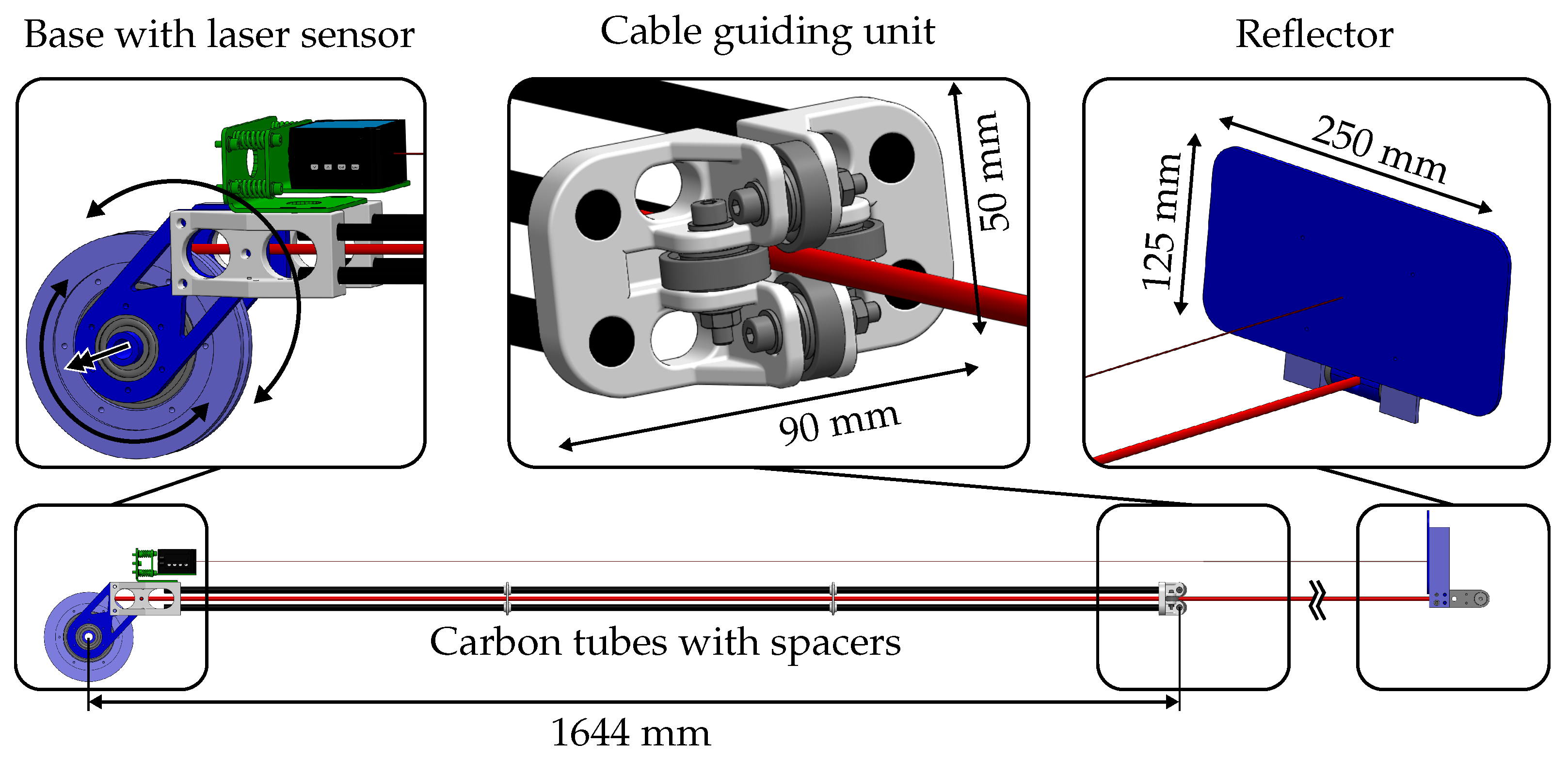
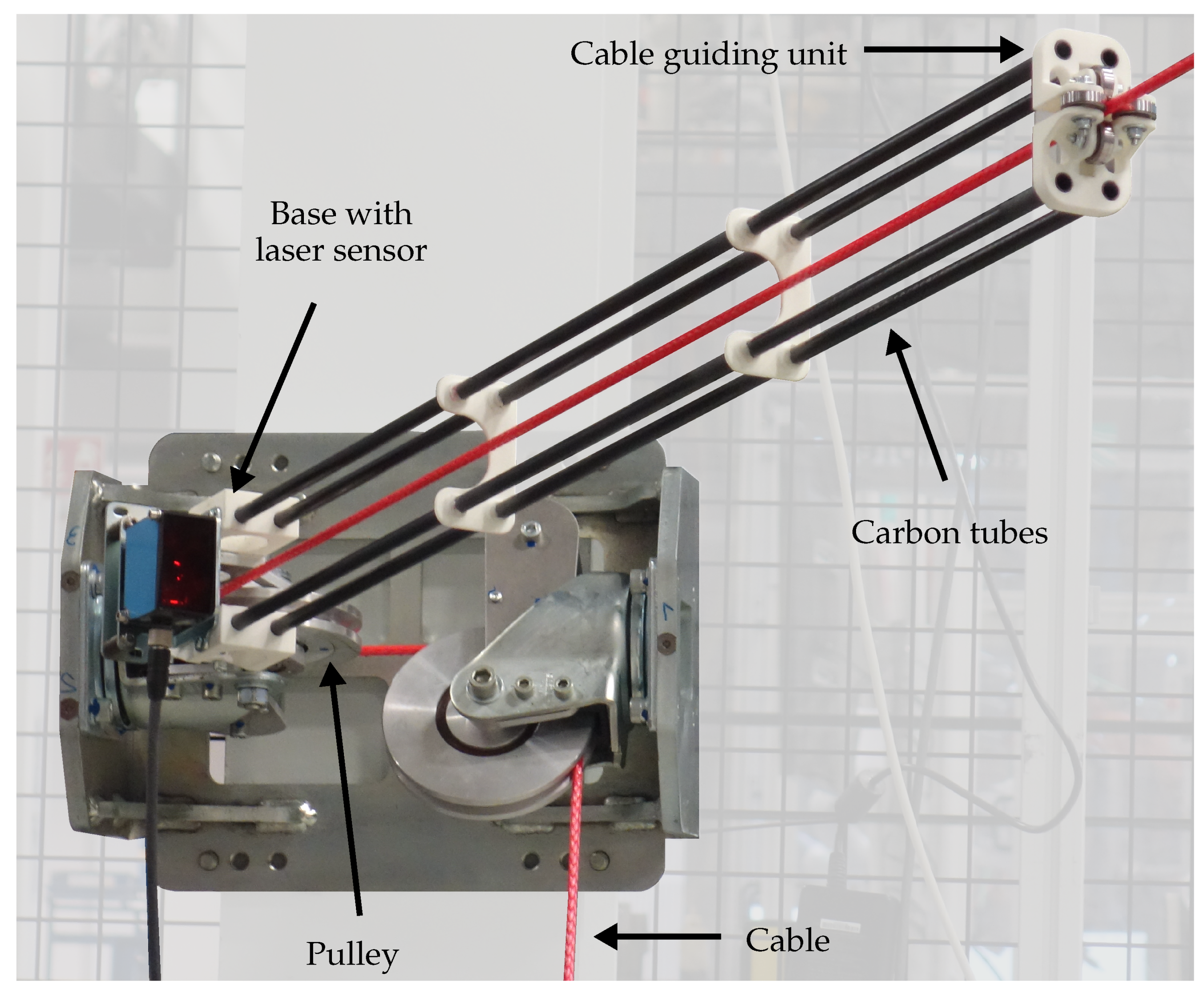
2.3. Mechanical Design

The mechanical design of the DCLM-Sensor is shown in Figure 4. The used materials are specified with different colors. The relation between material and color can be found in the caption of Figure 4. The weights of the components are listed in Table 1.
The DCLM-Sensor is designed to be lightweight in order to keep the additional force applied on the cable low. The three main parts, namely the base with the laser sensor, the cable guiding unit, and the reflector, are displayed in enlarged views in Figure 4.
The base of the DCLM-Sensor is attached to the pulley axis with a separate bearing. Thus, it can rotate independently from the pulley around the pulley axis. A laser sensor is attached on the structure of the base. The design is not restricted to a specific laser distance sensor model. In our experiments, a DL50-P2228 from SICK is chosen (for technical specifications see Table 2).
The two main selection criteria are high accuracy and the laser protection class. The laser protection class is limited to one since the system must meet safety regulations, especially if the laser beam does not hit the reflector and points in an arbitrary direction. The base and the cable guiding unit are connected with four carbon tubes. The cable guiding unit consists of four bearings which enclose the cable. Thus, if the cable changes its direction due to a change of the pose, the whole sensor unit follows this movement and the direction of the laser beam remains aligned with the cable direction. The third element is the reflector, which is attached to the cable-platform connector. It is oriented such that the cable direction is perpendicular to the reflector plane. A reflector size of 125 mm × 250 mm is chosen. To show that the measurement principle of the DCLM-Sensor works, the size of the reflector is chosen as large as possible, avoiding platform reflector collisions. In future developments it is intended to reduce the size of the reflector. The surface of the reflector is laminated with a reflector foil (SICK, Type: “Diamond Grade”). Figure 5 shows a picture of the real DCLM-Sensor installed at a pulley of the cable robot IPAnema 3.

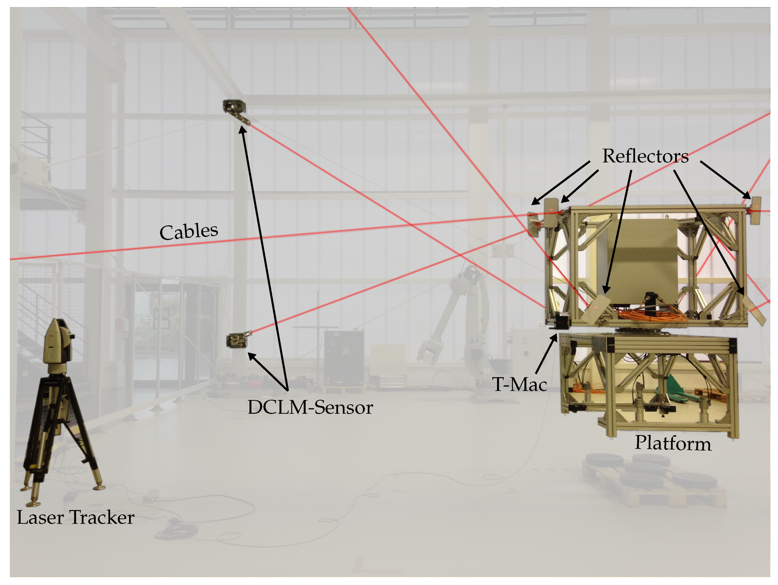
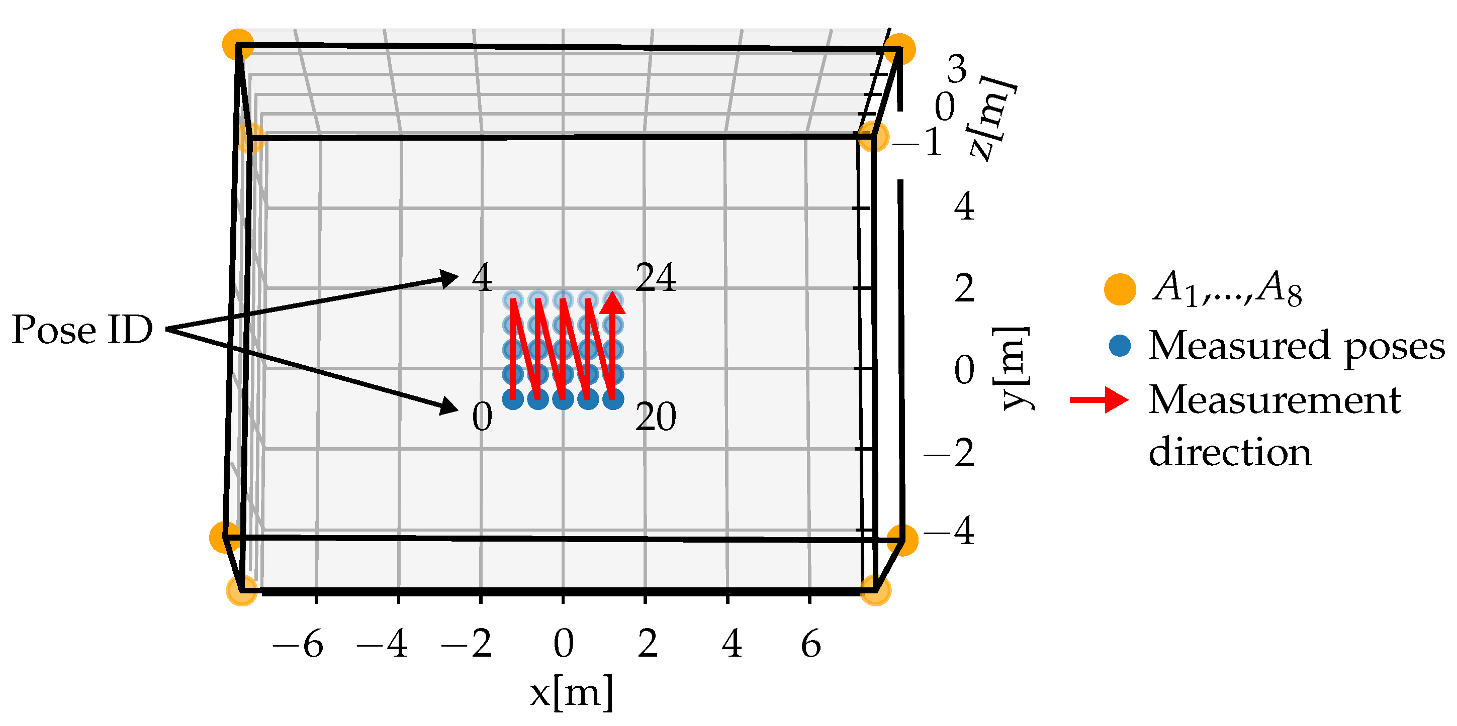
3. Experimental Accuracy Evaluation

The DCLM-Sensor accuracy is evaluated on the cable robot demonstrator IPAnema 3 at Fraunhofer IPA. The IPAnema 3 is a redundantly constrained cable robot with eight cables. The geometrical parameters are given in Table 3. A picture of the experimental setup is shown in Figure 6.
In the experiments, DCLM-Sensors are attached to each cable. As ground truth measurement of the cable length, a Leica laser tracker AT960 (https://www.hexagonmi.com/de-de/products/laser-tracker-systems/leica-absolute-tracker-at960, accessed on 4 February 2021) with a T-Mac attached to the platform is employed. With the T-Mac, it is possible to measure all six degrees of freedom with an accuracy given in Table 4. The DCLM-Sensor cable length measurement accuracy is evaluated with a grid of 25 static poses in an x-y-plane with z = 0 m. For the 25 evaluated poses and the specified laser tracker accuracy, the worst-case error for the measurement of the ground truth cable length amounts to ±0.337 mm. Worst-case means that the position measurement of the T-Mac has a maximum measurement error in addition to a maximum rotational accuracy error.
The evaluated poses in relation to the cable robot are visualized with blue dots in Figure 7. The eight proximal anchor points A 1 , ..., A 8 of the IPAnema 3 are marked with orange dots. The poses are evaluated in the order following the red arrow. The coordinates and the associated ID are given in Table 5. Compared to the size of the cable robot, the evaluated area is quite small, but due to the heavy end-effector the workspace of this cable robot setup is limited.
The measurement procedure at each pose is as follows:
The CDPR-platform moves to the measurement pose. After a waiting time of five seconds to let eventual vibrations subside, the pose measurements of the laser tracker and the cable length measurements of the DCLM-Sensors are logged and averaged over one second. After the measurement, the CDPR-platform moves to the next measurement pose and the measurement procedure starts again.

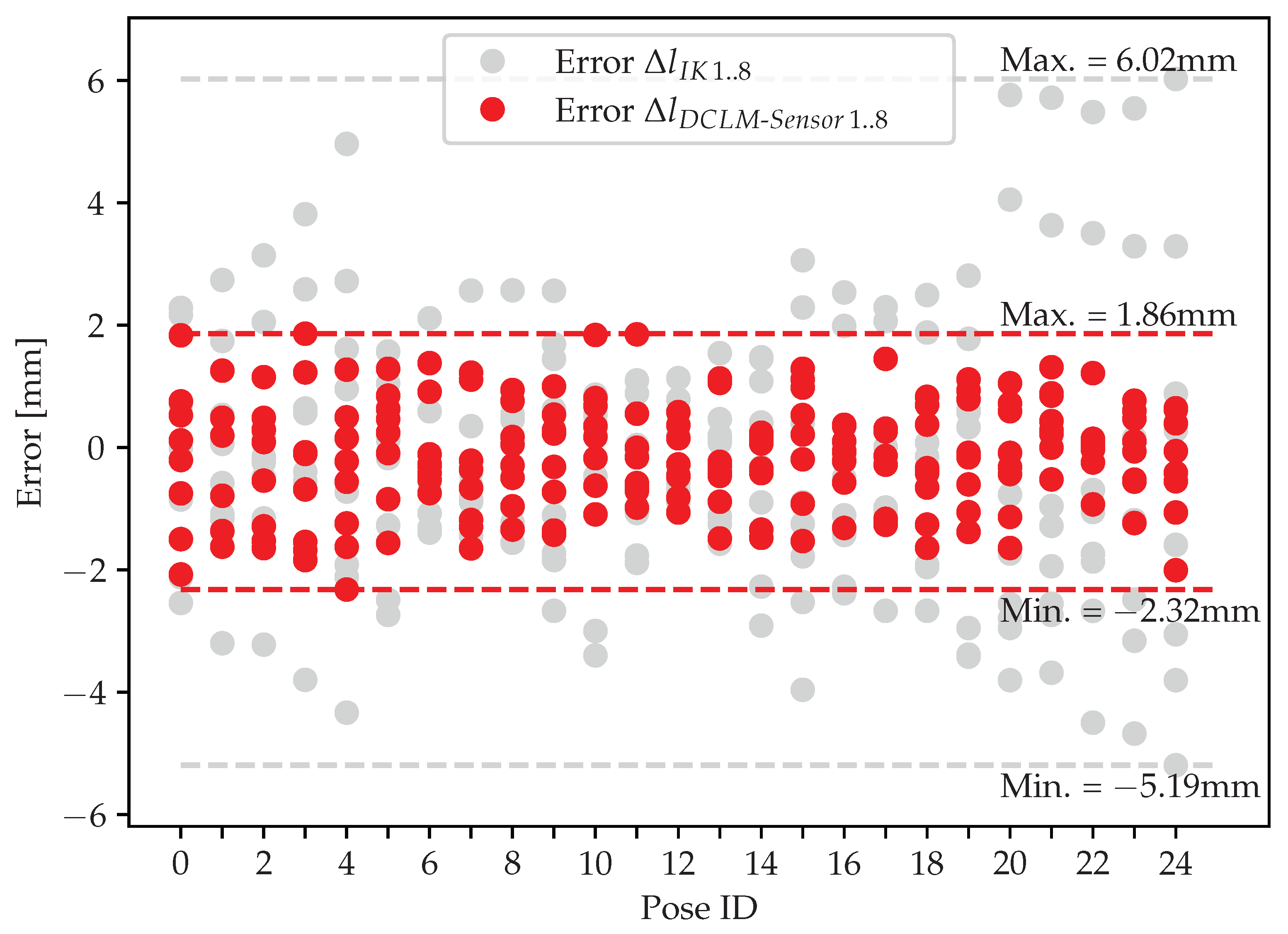
3.1. Accuracy Results of the DCLM-Sensor

The result of the accuracy evaluation is shown in Figure 8. The grey dots (Error Δ l IK 1 . . 8 ) display the error between the cable lengths commanded by the CDPR-controller and the ground truth cable lengths measured with the laser tracker for each pose and all eight cables. The cable lengths of the CDPR-controller are calculated through the inverse kinematic (IK) [16] and set with the motor encoders. The error of the cable lengths commanded by the CDPR-controller is between −5.19 mm and +6.02 mm. The mean value of the cable length error accounts to −0.292 mm and the standard deviation to 2.117 mm.
The red dots (Error Δ l D C L M - S e n s o r 1 . . 8 ) show the error between the cable lengths measured with the DCLM-Sensors and the ground truth cable lengths measured with the laser tracker for each pose and all eight cables. The error of the DCLM-Sensors is in the range from −2.32 mm to +1.86 mm, with a mean of −0.145 mm and a standard deviation of 0.883 mm.

3.2. Discussion of the Experimental Evaluation

The experimental evaluation shows that the measurement principle works as intended. All measured cable lengths of the DCLM-Sensors are >4 m. This means that according to the technical data of the SICK laser sensor (Table 4), the absolute measurement accuracy is equal to ±3 mm. Thus, the error of the cable length measurement is even less than specified in the data sheet of the SICK laser sensor.
Comparing the accuracy of the IK and the DCLM-Sensors, the standard deviation of the DCLM-Sensor measurement error is 58% lower. The maximum measurement error is reduced about 69%, the minimum about 55%. The mean error is close to zero for both cable length errors. Even taking the worst-case scenario of the ground truth cable length into account, there is a significant improvement in the determination of the cable length.
This means, using the cable length measurements of the DCLM-Sensors as feedback for the CDPR-controller, the cable lengths could be adjusted more accurately to the cable lengths calculated with the inverse kinematic. Increasing the cable length precision is assumed to also increase the pose accuracy of CDPRs.
The accuracy deviations of the DCLM-Sensor are assumed to be dependent on:
-
The measurement accuracy of the laser sensor;
-
Misalignment of cable and laser due to cable sagging.
The second point especially influences the measurement accuracy of the DCLM-Sensor at the wrench-feasible workspace borders, where the cable can be long and the cable force low. Thus, the cable sags and the laser is not aligned parallel to the cable (see Section 2.2). In the worst-case scenario, the laser does not hit the reflector anymore. During the trials to evaluate the DCLM-Sensor accuracy with a larger grid than presented in this paper, it has been found that the sensor loses the reflector if the cable force is lower than 200 N, with a cable length above 10.7 m, and an angle between the cable and the horizontal plane below 8.8°. The point where the laser sensor loses its reflector is dependent on the cable force, the cable length, and the angle of the cable which influences the impact of the gravity on the cable.
To further improve the accuracy of the DCLM-Sensor, one could use a more accurate laser sensor and address the misalignment of the laser sensor. The alignment inaccuracy could be reduced through a counterweight which reduces the force of the DCLM-Sensor on the cable that increases the misalignment due to sagging.

4. Conclusions and Outlook

In this paper, we present a new direct cable length measurement sensor based on a laser distance sensor. With this sensor, it is possible to directly measure the cable length between the proximal and distal anchor points of a cable-driven parallel robot according to the standard pulley kinematic, assuming the cables to be straight lines. The mechanical design and the kinematic of the direct cable length sensor are presented. Furthermore, the measurement principle and its accuracy are experimentally evaluated on the cable robot demonstrator IPAnema 3. The experimental evaluation shows that the measurement principle works as intended and the accuracy is within the range of −2.32 mm and +1.86 mm. Compared to the standard CDPR-controller, the standard deviation of the cable length error is 58% lower.
The absolute measurement of the cable length enables new possibilities like the determination of the initial cable lengths after the installation of the cable robot, or the automatic recalibration of the home pose. In future works, it is planned to integrate the cable length feedback of the direct cable length measurement sensors in the CDPR-controller. Based on the feedback of the direct cable length measurement sensors, the cable lengths can be corrected in order to increase the accuracy of CDPRs.

Author Contributions

Conceptualization, C.M., M.F. and J.T.S.; software, C.M., M.F.; writing—original draft preparation, C.M.; writing—review and editing, M.F. and J.T.S.; supervision, A.P. All authors have read and agreed to the published version of the manuscript.

Funding

This research received no external funding.

Conflicts of Interest

The authors declare no conflict of interest.

References

  1. Dallej, T.; Gouttefarde, M.; Andreff, N.; Hervé, P.E.; Martinet, P. Modeling and vision-based control of large-dimension cable-driven parallel robots using a multiple-camera setup. Mechatronics 2019, 61, 20–36. [Google Scholar] [CrossRef] [Green Version]
  2. Schmidt, V.; Pott, A. Increase of Position Accuracy for Cable-Driven Parallel Robots Using a Model for Elongation of Plastic Fiber Ropes. In New Trends in Mechanism and Machine Science; Wenger, P., Flores, P., Eds.; Springer: Cham, Switzerland, 2017; Volume 43, pp. 335–343. [Google Scholar]
  3. Merlet, J.-P. MARIONET, A Family of Modular Wire-Driven Parallel Robots. In Advances in Robot Kinematics (ARK); Lenarcic, J., Stanisic, M., Eds.; Springer: Dordrecht, The Netherlands, 2010; pp. 53–61. [Google Scholar]
  4. Schmidt, V.L. Modeling Techniques and Reliable Real-Time Implementation of Kinematics for Cable-Driven Parallel Robots Using Polymer Fiber Cables; Fraunhofer Verlag: Stuttgart, Germany, 2017. [Google Scholar]
  5. Pott, A.; Mütherich, H.; Kraus, W.; Schmidt, V.; Miermeister, P.; Verl, A. IPAnema: A family of Cable-Driven Parallel Robots for Industrial Applications. In Cable-Driven Parallel Robots; Bruckmann, T., Pott, A., Eds.; Springer: Berlin/Heidelberg, Germany, 2013; Volume 12, pp. 119–134. [Google Scholar]
  6. Lamaury, J.; Gouttefarde, M. Control of a Large Redundantly Actuated Cable-Suspended Parallel Robot. In Proceedings of the 2013 IEEE International Conference on Robotics and Automation, Karlsruhe, Germany, 6–10 May 2013; pp. 4659–4664. [Google Scholar]
  7. Alexandre dit Sandretto, J.A.; Trombettoni, G.; Daney, D.; Chabert, G. Certified Calibration of a Cable-Driven Robot Using Interval Contractor Programming. In Computational Kinematics; Thomas, F., Perez Gracia, A., Eds.; Springer: Dordrecht, The Netherlands, 2014; Volume 15, pp. 209–217. [Google Scholar]
  8. Miermeister, P.; Pott, A. Auto Calibration Method for Cable-Driven Parallel Robots Using Force Sensors. In Latest Advances in Robot Kinematics; Lenarcic, J., Husty, M., Eds.; Springer: Dordrecht, The Netherlands, 2012; pp. 269–276. [Google Scholar]
  9. Piao, J.; Jin, X.; Choi, E.; Park, J.O.; Kim, C.S.; Jung, J. A Polymer Cable Creep Modeling for a Cable-Driven Parallel Robot in a Heavy Payload Application. In Cable-Driven Parallel Robots; Gosselin, C., Cardou, P., Bruckmann, T., Pott, A., Eds.; Springer: Cham, Switzerland, 2018; Volume 53, pp. 62–72. [Google Scholar]
  10. Dallej, T.; Gouttefarde, M.; Andreff, N.; Michelin, M.; Martinet, P. Towards vision-based control of cable-driven parallel robots. In Proceedings of the 2011 IEEE/RSJ International Conference on Intelligent Robots and Systems, San Francisco, CA, USA, 25–30 September 2011; pp. 2855–2860. [Google Scholar]
  11. Garant, X.; Campeau-Lecours, A.; Cardou, P.; Gosselin, C. Improving the Forward Kinematics of Cable-Driven Parallel Robots Through Cable Angle Sensors. In Cable-Driven Parallel Robots; Gosselin, C., Cardou, P., Bruckmann, T., Pott, A., Eds.; Springer: Cham, Switzerland, 2018; Volume 53, pp. 167–179. [Google Scholar]
  12. Merlet, J.-P. Direct Kinematics of CDPR with Extra Cable Orientation Sensors: The 2 and 3 Cables Case with Perfect Measurement and Ideal or Elastic Cables. In Cable-Driven Parallel Robots; Gosselin, C., Cardou, P., Bruckmann, T., Pott, A., Eds.; Springer: Cham, Switzerland, 2018; Volume 53, pp. 180–191. [Google Scholar]
  13. Merlet, J.-P.; Daney, D. A portable, modular parallel wire crane for rescue operations. In Proceedings of the 2010 IEEE International Conference on Robotics and Automation, Anchorage, AK, USA, 3–7 May 2010; pp. 2834–2839. [Google Scholar]
  14. Merlet, J.-P. Improving cable length measurements for large CDPR using the Vernier principle. In Cable-Driven Parallel Robots; Pott, A., Bruckmann, T., Eds.; Springer: Cham, Switzerland, 2019; Volume 74, pp. 47–58. [Google Scholar]
  15. Pott, A. Cable-Driven Parallel Robots: Theory and Application; Springer: Cham, Switzerland, 2018; Volume 120. [Google Scholar]
  16. Pott, A. Influence of Pulley Kinematics on Cable-Driven Parallel Robots. In Latest Advances in Robot Kinematics; Lenarcic, J., Husty, M., Eds.; Springer: Dordrecht, The Netherlands, 2012; pp. 197–204. [Google Scholar]
Figure 1. Schematic sketch of the DCLM-Sensor.
Robotics 10 00060 g001
Figure 2. Sketch of the worst-case scenario due to cable sagging.
Robotics 10 00060 g002
Figure 3. Worst-case cable length error due to sagging.
Robotics 10 00060 g003
Figure 4. Mechanical design of the DCLM-Sensor. (Materials: grey/green ↔ steel; white ↔ PLA12; black (except for the laser sensor) ↔ carbon; blue (except for the laser sensor) ↔ aluminium; red ↔ dyneema cable.)
Robotics 10 00060 g004
Figure 5. DCLM-Sensor installed at a pulley of the cable robot IPAnema 3.
Robotics 10 00060 g005
Figure 6. Experimental evaluation of the DCLM-Sensors on the IPAnema 3.
Robotics 10 00060 g006
Figure 7. Measured poses to evaluate the DCLM-Sensor accuracy.
Robotics 10 00060 g007
Figure 8. Cable length error of IK and DCLM-Sensors of all eight cables.
Robotics 10 00060 g008
Table 1. Weights of the DCLM-Sensor components.
ComponentWeight [g]
Base with laser sensor (without pulley)10821325
Carbon tubes with spacers148
Cable guiding unit95
Reflector (without cable-platform connector)325
Table 2. Technical specification of the SICK laser distance sensor DL50-P2228 (https://www.sick.com/de/en/p/p346664, accessed on 4 February 2021).
Measuring Range200 ... 50,000 mm (with Reflector Foil)
Typ. repeatability (1 σ )0.25 mm (moving average set to slow)
AccuracyDistance ≤ 4 m: ±5 mm; Distance > 4 m: ±3 mm
Output rate2.5 ms
Table 3. Geometrical parameters of the cable robot IPAnema 3.
Cable IndexProximal Anchor PointsDistal Anchor PointsPulley Radii
iA [m]B [m] r p [m]
1 [ 7.6029 , 5.5952 , 3.5665 ] T [ 0.5488 , 0.46 , 0.48 ] T 0.057
2 [ 7.5238 , 5.5789 , 3.5745 ] T [ 0.5488 , 0.46 , 0.48 ] T 0.057
3 [ 7.4614 , 5.5621 , 3.7536 ] T [ 0.5488 , 0.46 , 0.48 ] T 0.057
4 [ 7.3114 , 5.6113 , 3.7408 ] T [ 0.5488 , 0.46 , 0.48 ] T 0.057
5 [ 7.6126 , 5.5812 , 0.7817 ] T [ 0.36 , 0.7488 , 0.48 ] T 0.057
6 [ 7.5427 , 5.5851 , 0.8525 ] T [ 0.36 , 0.7488 , 0.48 ] T 0.057
7 [ 7.7641 , 5.5694 , 0.9384 ] T [ 0.36 , 0.7488 , 0.48 ] T 0.057
8 [ 7.6959 , 5.6008 , 0.9036 ] T [ 0.36 , 0.7488 , 0.48 ] T 0.057
Table 4. Technical specification of the Leica AT960 with T-Mac (valid for a measuring time of one second and a totally static measurement).
Position accuracy±15 µm + 6 µ m / m
Typical rotation accuracy±0.01°
Table 5. Coordinates of the measured poses in the plane z = 0 m.
ID0123456789101112
x [m]−1.2−1.2−1.2−1.2−1.2−0.6−0.6−0.6−0.6−0.6000
y [m]−1.2−0.600.61.2−1.2−0.600.61.2−1.2−0.60
ID131415161718192021222324
x [m]000.60.60.60.60.61.21.21.21.21.2
y [m]0.61.2−1.2−0.600.61.2−1.2−0.600.61.2
Publisher’s Note: MDPI stays neutral with regard to jurisdictional claims in published maps and institutional affiliations.

