Article

FES Cycling and Closed-Loop Feedback Control for Rehabilitative Human–Robot Interaction

1
Department of Mechanical Engineering, The University of Alabama, Tuscaloosa, AL 35487, USA
2
Department of Mechanical and Aerospace Engineering, Syracuse University, Syracuse, NY 13244, USA
3
Department of Mechanical and Aerospace Engineering, University of Florida, Gainesville, FL 32611, USA
*
Author to whom correspondence should be addressed.
These authors contributed equally to this work.
Robotics 2021, 10(2), 61; https://doi.org/10.3390/robotics10020061
Submission received: 16 February 2021 / Revised: 28 March 2021 / Accepted: 14 April 2021 / Published: 22 April 2021
(This article belongs to the Special Issue Human–Robot Collaboration)

Abstract

:
For individuals with movement impairments due to neurological injuries, rehabilitative therapies such as functional electrical stimulation (FES) and rehabilitation robots hold vast potential to improve their mobility and activities of daily living. Combining FES with rehabilitation robots results in intimately coordinated human–robot interaction. An example of such interaction is FES cycling, where motorized assistance can provide high-intensity and repetitive practice of coordinated limb motion, resulting in physiological and functional benefits. In this paper, the development of multiple FES cycling testbeds and safeguards is described, along with the switched nonlinear dynamics of the cycle–rider system. Closed-loop FES cycling control designs are described for cadence and torque tracking. For each tracking objective, the authors’ past work on robust and adaptive controllers used to compute muscle stimulation and motor current inputs is presented and discussed. Experimental results involving both able-bodied individuals and participants with neurological injuries are provided for each combination of controller and tracking objective. Trade-offs for the control algorithms are discussed based on the requirements for implementation, desired rehabilitation outcomes and resulting rider performance. Lastly, future works and the applicability of the developed methods to additional technologies including teleoperated robotics are outlined.

1. Introduction

For individuals with movement impairments due to neurological injuries (NIs) such as stroke, spinal cord injury or traumatic brain injury, their activities of daily living and independence may be compromised [1,2,3]. Movement impairments are characterized by reduced leg coordination, abnormal muscle activity, decreased muscle strength and limited endurance. Therefore, novel rehabilitation and therapeutic methods are needed to improve and restore function in these populations. Functional electrical stimulation (FES) and rehabilitation robotics have been used independently and together to facilitate lower-limb movement and yield cardiovascular, neurological and physiological benefits [4,5,6]. A critical factor for inducing neuroplasticity and lasting mobility improvements is the promotion of high-intensity and repetitive practice of coordinated limb movements coupled with neural feedback [7,8,9].
Functional electrical stimulation (FES) of the lower body muscles is often used by therapists to facilitate cycling and yield improvements in musculoskeletal and cardiorespiratory fitness as well as other neurological, physiological and psychological measures [10,11,12,13]. Stationary FES cycling is a popular rehabilitative therapy because fall risks associated with other therapies are mitigated and it is relatively inexpensive compared to other robotic rehabilitation devices. Moreover, motorized assistance (i.e., incorporating an electric motor to the stationary cycle [14,15]) in FES cycling facilitates continuous and consistent pedaling and can maximize the training time by reducing the duty cycle of electrical stimulation (thereby delaying the early onset of neuromuscular fatigue). Because the inclusion of motorized assistance in FES cycling results in intimate coordinated human–robot interaction, the design, safety and stability of the closed-loop control algorithms for the human and the robot (i.e., cycle) must be systematically addressed.
The interactions between the human and cycle can be designed and controlled to achieve shared, separate and coupled goals in FES cycling. For a shared control objective, the rider’s muscles and the cycle’s motor jointly contribute to the same objective (e.g., attaining a desired cadence on the FES cycle) [15,16]. Similarly, when dealing with separate objectives, the cycle’s motor can be tasked with keeping the cycle at a desired cadence, while the rider’s muscles maintain the desired interaction torque [17,18]. Finally, the rider’s muscles and the cycle’s motor can also have coupled tracking objectives, as in the case of indirect torque control or admittance control [19,20]. While each of these methods has their inherent advantages (e.g., cadence tracking requires no torque feedback), admittance control [21] is of particular interest because it modifies the cycle’s behavior based on the interaction torque between the cycle and rider and offers a method to promote safety over performance by resolving conflicts in motion between the robot and human [22]. Furthermore, admittance control has been widely used for rehabilitation robots in the past decade [23,24,25] as well as for hybrid exoskeletons (which combine FES with rehabilitation robotics, as in FES cycling) [26,27].
For the aforementioned objectives, the authors implemented two closed-loop control approaches on FES-cycles: robust [15,17,19] and adaptive [16,18,20] control. A fundamental use of feedback for automatic control is to provide robustness to uncertainty or undesired effects such as disturbances. For FES cycling, uncertainty in the human includes neuromuscular parameters that are difficult to measure (e.g., viscous–elastic effects of the muscle tissue) and other factors such as changes in metabolism, hydration and spastic muscle contractions during pedaling [15]. Uncertainty and disturbances include the cycle’s unknown damping and changes in motor load. A robust control approach exploits high-gain and high-frequency (e.g., sliding mode) tools to compensate for the known upper bounds. To illustrate stability, the robust control design can be coupled with a Lyapunov-based stability analysis to guarantee the tracking objective is achieved and the error signals and control inputs always remain bounded [28].
Adaptive control compensates for dynamic uncertainties by exploiting inherent properties of the system (e.g., uncertain constant parameters that satisfy the linear-parameters property [29,30]) or a characteristic of the desired task or process (e.g., a periodicity or iterative nature of movement [31,32]). In adaptive control, an estimate of an uncertain function or unknown parameter is computed using an adaptive update law that exploits the feedback of the system (e.g., tracking errors). A caveat is that the adaptive estimate may not converge to the true parameter value [30]. However, even without guaranteeing the convergence of the estimated dynamics, the tracking objective can still be achieved, and the estimate can be guaranteed to remain bounded. Due to the periodic nature of cycling, an adaptive repetitive learning control approach is motivated. A key difference between repetitive learning control and classical adaptive control is that learning controllers do not require knowledge of the structure of the uncertain function or parameter. Repetitive learning control is suited for systems that track periodic or iterative trajectories, as is the case for FES cycling. In adaptive and learning-based control, a stability analysis ensures the tracking objectives are achieved and both the adaptive estimates and control inputs remain bounded.
In this paper, control objectives and methods are presented for FES cycling in the context of human–robot interaction. Specifically, this paper addresses the scenarios in which the human and motorized cycle have shared, separate and coupled tracking objectives that yield significant challenges in the control design and stability analysis of the human–robot system. To address the challenges, the authors’ previous work on FES cycling is discussed [15,16,17,18,19,20] for each combination of controller (robust and adaptive) and tracking objective (cadence, direct torque and indirect torque tracking). By comparing and contrasting the results, many considerations involved in intimate human–robot interaction are discussed. The motivation behind this paper is to synthesize and coalesce the authors’ recent findings surrounding FES cycling in a tutorial-like fashion to highlight the control design, tracking objectives and experimental results.
The rest of the paper is organized as follows. Section 2 describes the Materials and Methods and includes a technical overview of neuromuscular electrical stimulation (NMES). Additionally, two experimental testbeds (a single-crank and split-crank FES cycle) are described including the cycles’ mechanical components, sensors and electric motors, the electrical stimulation unit and hardware and software safety measures. A nonlinear model of the cycle–rider system that includes the effects of switching across muscle and motor inputs is developed and used for the subsequent control design. Section 3 describes the results pertaining to cadence, direct torque and indirect torque control objectives, including mathematical details of the error signals that quantify the tracking objectives. Within each tracking objective, robust and adaptive control results are described, and brief sketches of the control inputs are provided. Section 4 presents a discussion of the results and insights into future work. Section 5 provides concluding remarks.

2. Materials and Methods

The following subsections provide a detailed description of the electrical and mechanical components comprising single and split-crank FES cycle–rider systems. Because the cycles are powered and controlled, they are considered robotic as well as mechatronic systems. Furthermore, because the cycles are physically coupled to humans (i.e., the rider), they are also considered powered exoskeletons (the FES cycles can also be considered as end-effector exoskeletons), as well as rehabilitation robots.

2.1. Functional Electrical Stimulation

Neuromuscular electrical stimulation (NMES) is the application of electrical stimuli to skeletal muscles to produce tetanic contractions (i.e., thereby activating lower motor neurons by stimulating nerve fibers) [6,33]. NMES is referred to as functional electrical stimulation (FES) when electrically elicited muscle contractions are coordinated to perform a functional task (e.g., walking [34,35,36], cycling [14,15] and upper-limb motion [37]). FES enables functions by replacing or assisting a user’s voluntary muscle efforts.
The muscle response to electrical stimuli is modulated by adjusting three stimulation parameters: pulse frequency, pulse amplitude and pulse duration (also called pulse width). Figure 1 depicts the stimulation parameters of a pulse train. Pulse frequency is the number of pulses applied per second. A stimulus frequency of 30–80 Hertz (Hz) is typically needed to achieve a tetanic contraction [33]. A constant stimulation frequency is used in practice to produce a smooth muscle contraction and avoid discomfort [38]. A high stimulation frequency is usually associated with a faster muscular fatigue rate [39]. The pulse amplitude or pulse intensity is quantified in milliamps (mA). The pulse width or pulse duration is the time span of a single pulse, and it is quantified in microseconds (µs). Relatively high stimulation amplitudes and long duration pulses activate more motor units, thus increasing the contraction force [33]. Commonly, during neuromuscular stimulation, either the pulse amplitude or duration is fixed and the other factor is controlled to evoke a desired muscle response. Factors which determine the fixing or controlling of the stimulation pulse amplitude and duration include an individual’s tolerance to stimulation and the electrical stimulation unit specifications.
In the cycling results presented in Section 3, the stimulation frequency was fixed at 60 Hz. The pulse amplitude was fixed at 90 mA for the quadriceps, 80 mA for the hamstrings and 70 mA for the gluteal muscle groups. The developed muscle controllers in Section 3 determined the pulse duration (or pulse width) of each muscle. The pulse duration was varied because the electrical stimulation unit (i.e., the Hasomed Rehastim neuromuscular electrical stimulator) had a greater resolution for the pulse width (in a range of 20–500 µs in steps of 1 µs) than the current amplitude (in the range 0–126 mA in steps of 2 mA). Stimulation waveforms are typically either monophasic (unidirectional pulses) or biphasic. Furthermore, pulses can be symmetric or asymmetric in shape. Stimulation waveforms using doublets [40,41] and N-let pulse trains [42] have been developed as alternatives to traditional stimulation waveforms with the motivation to reduce muscle fatigue. The effectiveness of the electrical stimuli to evoke muscle contractions depends on the size, number and placement of electrodes over the muscle belly [38,43]. Typical surface (i.e., transcutaneous) electrodes are self-adhesive to ensure a robust skin–electrode interface. Larger electrodes activate more tissue area, thus decreasing the current density [33,38]. Alternatively, smaller electrodes increase the current density at the expense of inducing discomfort or pain [38]. Electrodes can be arranged in a monopolar or bipolar configuration [6]. In both configurations, only one of the electrodes is active at any given time. In the monopolar configuration, the other electrode is the reference electrode or ground. In a bipolar configuration, the active and the reference electrodes switch to reverse the current flow and thus stimulate the tissue underneath both electrodes (i.e., the current is distributed) [44].
Conventional synchronous stimulation uses a single-channel pair of surface electrodes to deliver the pulse trains to a muscle. However, conventional single-channel electrical stimulation is prone to accelerate muscle fatigue due to the need for high stimulation frequencies. Alternatively, asynchronous stimulation uses multiple pairs of electrodes to target multiple areas of a muscle [43,46]. In FES cycling, surface electrodes are applied over the quadriceps, hamstrings and gluteal muscle groups using a singlemchannel in a bipolar configuration and using biphasic symmetric pulses [14,15,47]. In our experiments, electrodes were placed in proximal–lateral and distal–medial positions over the muscles in accordance with the manufacturer’s placement manual.
Limitations of FES arise due to the reduced efficiency and selectivity in recruiting motor units, and the early onset of neuromuscular fatigue [6,33,38]. Neuromuscular fatigue is the decay in the peak force for a given stimulation input. The rate of muscle fatigue is faster with FES than with voluntary contractions, which is possibly due to the reverse recruitment order of motor units (in opposition to the physiological size principle) or due to evidence suggesting that electrical stimulation recruits motor units in a nonselective, synchronous and spatially fixed pattern [48,49]. This simultaneous activation of muscle fibers might produce uncoordinated or inefficient motion rather than graded force generation with centrally evoked contractions [38]. In addition to muscle fatigue, the control of FES is challenging due to the nonlinear muscle activation dynamics [50] and the presence of an electromechanical input delay. Despite the limitations and challenges associated with FES, it has medical benefits such as increased blood flow, increased muscle mass, improved muscle strength, an improved joint range of motion and increased bone mineral density [6,38]. In therapeutic applications, FES is used to counteract muscle atrophy and improve voluntary function by inducing lasting physiological changes that remain after the electrical stimulation is removed and physical training is completed [6,38]. An active research topic is the examination of the long-term functional and therapeutic benefits of hybrid rehabilitation methods that combine FES and robotic machines (e.g., a motorized cycle or powered exoskeleton) that provide continuous cycling or locomotion training.

2.2. Single-Crank FES Cycle

For the subsequent control results, a custom FES cycle was developed. Compared to commercially available options (e.g., the RT300 from Restorative Therapies [38,51]), a new cycle was required to implement the low-level real-time control of the cycle’s motor and rider’s muscles. The single-crank FES cycle was constructed by retrofitting a Terratrike Rover x8 recumbent tricycle with a variety of custom mounts, sensors and actuators. Prior to adding any equipment, the original chain, crankset, pedals and rear derailleur were removed. To measure the crank arm’s angular position and velocity (i.e., cadence), a shaft encoder was mounted underneath the cycle’s boom or crank extender. A pair of spur gears were then affixed to the encoder’s shaft and the cycle’s spindle. To ensure the index of encoder maps directly to the position of the crank arm, it was necessary for each gear ti gave an identical number of teeth, ensuring that one revolution of the crank arm was equivalent to one revolution of the encoder.
Once the gear was affixed to the cycle’s spindle, an SRM Science Road power-meter was attached to the spindle. The power-meter was used to wirelessly measure the interaction torque between the cycle and the rider, and the signal was routed through an SRM Torque Analysis System. To securely fix the rider’s feet to the cycle’s pedals, orthotic boots (Ossur Rebound Air Tall) were mounted to the pedals. The boots maintained the sagittal alignment of the legs and prevented the dorsiflexion/plantarflexion of the ankles.
To equip the cycle with an electric motor, a motor mounting plate was attached to the cycle’s frame. A 250 W DC electric motor was interfaced with the drive chain through a sprocket or spur gear. The lateral positioning of the motor and tensioners was then adjusted such that the interfacing of the chain with the power-meter, motors, tensioners and cassette was as straight as possible. Note, as a result of removing the rear derailleur, the cycle lost the ability to shift gears and effectively became a single-speed freewheel cycle. Once the cycle’s modifications were completed, it was placed on a bike trainer and riser rings.
The cycle’s motor was powered with an ADVANCED Motion Controls (AMC) PS300W24, (AMC, Camarillo, CA, USA) power supply and controlled with an AB25A100 (AMC, Camarillo, USA) motor driver. A FC15030 (AMC, Camarillo, USA) filter card was added between the driver and the motor to reduce electrical noise. AMC supported the development of this testbed by providing discounts on their items.To interface with the sensors and the motor driver, a Quanser Q-PIDe data acquisition (DAQ) board was connected to a desktop computer running Windows 10. All controllers were implemented in MATLAB/Simulink using Quanser’s Quarc software at 500 Hz.
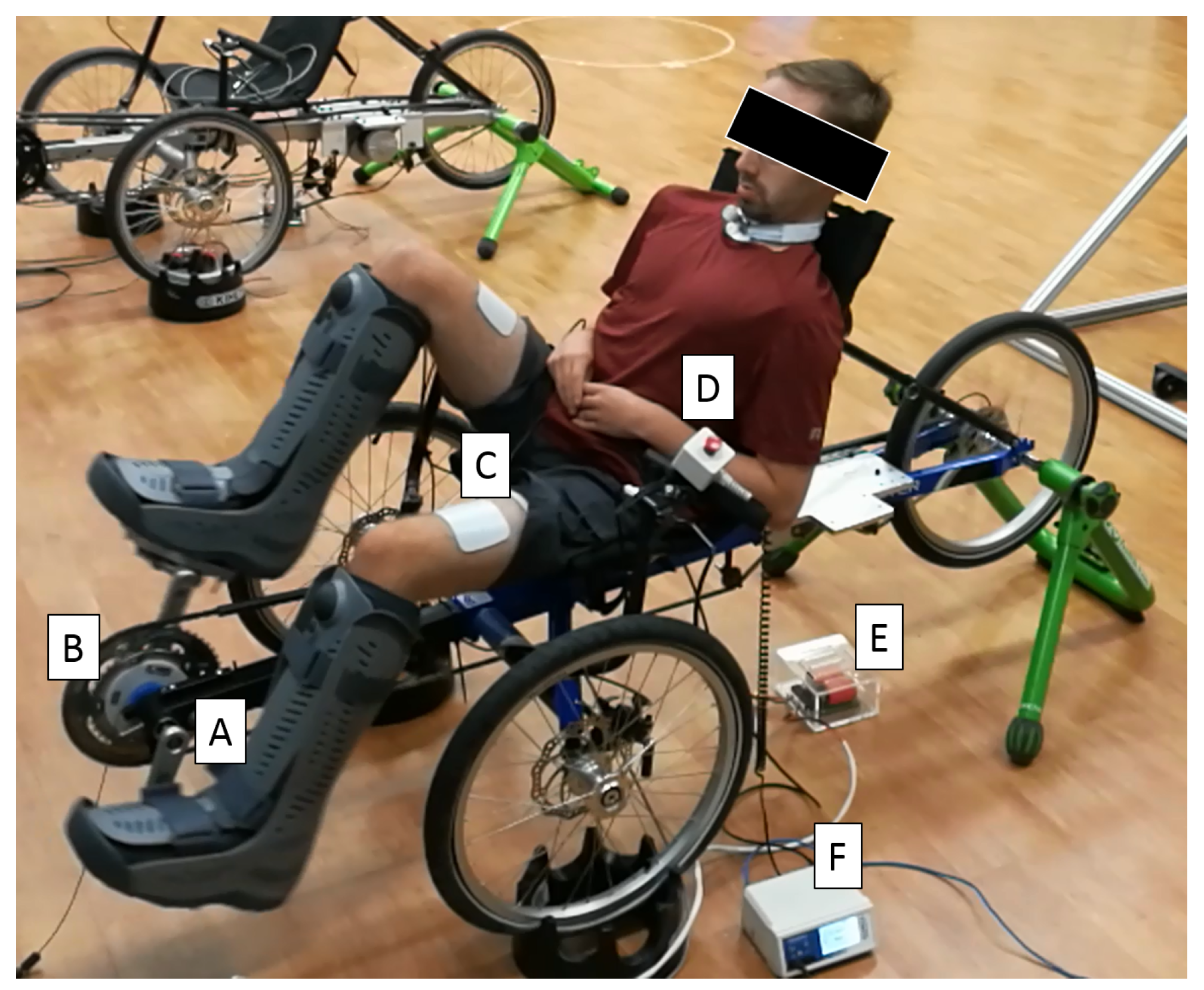
The rider’s leg muscles were stimulated with a Hasomed Rehastim neuromuscular electrical stimulator, which interfaced with the desktop computer. The stimulator delivered transcutaneous, symmetric, biphasic and rectangular pulses via bipolar self-adhesive PALS® electrodes (surface electrodes for this study were provided by Axelgaard Manufacturing Co., Ltd., Fallbrook, CA, USA) to the rider’s quadriceps, hamstrings and gluteal muscle groups at respective amplitudes of 90 mA, 80 mA and 70 mA. Stimulation was applied at a frequency of 60 Hz, and the pulse width of each muscle group was modulated automatically by the muscle controllers and calculated in MATLAB/Simulink. A rider seated on the motorized FES cycle is depicted in Figure 2.

2.3. Split-Crank FES Cycle

FES cycles can mask asymmetries in the rider due to coupled pedals and a single torque sensor. The coupled pedals allow the rider to effectively “cheat” by using their unimpaired side to pedal the cycle. Previous works in the literature include methods to promote symmetric rehabilitation by isolating the torque contributions of each leg by instrumenting cycles with torque sensors on each pedal [52,53], decoupling the pedals (i.e., split-crank cycling) [54,55] or pedaling with one leg at a time [56]. Furthermore, results such as [53] derived symmetry controllers to stimulate each leg differently. Because FES cycling has been shown to improve symmetry in hemiplegic individuals [52], further research into asymmetric rehabilitation is warranted.
For these reasons, the authors constructed a split-crank FES cycle in a similar manner to the single-crank FES cycle with a few notable exceptions; namely, the rear cassette of the cycle was removed and replaced with a rear hub assembly which had single-speed freewheel cogs on either side of the tire on the rear axle. This effectively allowed the cycle to be propelled, or mechanically powered, using two chains, with one on either side of the cycle. Another notable difference was that the spindle in the bottom bracket was cut into two equal-length pieces. By severing the spindle, the two pedals operated independently and consequently could be controlled independently.
Subsequently, the power-meter/encoder assembly was mirrored around the bottom bracket, along with the motor/tensioner assembly. Finally, a second chain was added and tensioned. Thus, the split-crank cycle used two encoders, two power-meters, two power supplies, two motor drivers, two motors, two filter cards and two chains. As with the single-crank cycle, the split-crank cycle was interfaced with the desktop computer using a single DAQ board; however, it required twice the number of input/output ports due to the increased number of sensors and actuators.

2.4. Safety Measures

Safety is paramount for any physical human–robot interaction, especially when interacting with people who have a movement impairment and may have a myriad of factors (e.g., type and severity of injury, time since injury, rehabilitation history, exercise habits, etc.) that can affect their body, muscles, bone structure, etc., and lead to increased vulnerability. Some injuries affect sensory function, and the individual may not be able to detect and report an adverse or harmful event or motion. For this reason, each FES cycle was equipped with a number of hardware and software safety measures to protect the rider.
In terms of hardware, each cycle was equipped with an emergency stop button within easy reach of the rider. When the button was pressed, power to the motor and electrical stimulation units was interrupted and needed to be reset by hand before the cycle could resume normal operation. The cycle was also outfitted with a chain guide tube to protect the rider’s hands and legs during cycle operation. To further ensure the safety of the rider, additional safeguards were built into the cycle by design. For example, by using a tricycle with a low center-of-gravity, there was a low risk of tipping or falling. Moreover, when seating the rider, the operator needed to adjust the rider’s seat to ensure there was a minimum bend of 15° in the rider’s knee when their leg was fully extended. Not only did this bend assist with determining the rider’s stimulation pattern, but it also prevented the hyperextension of the rider’s knees. Additionally, both the motor and muscle controller needed to be designed to ensure predictable and stable performance in all operating conditions. Software safety measures included maximum and minimum cadence limits (at steady state-operation), maximum torque limits, maximum current limits, maximum run-time limits and a software emergency stop for the study staff member operating the cycle.

2.5. Dynamics

To properly apply current to the cycle’s electric motor, stimulate the rider’s muscles and conduct a rigorous stability analysis, a basic understanding of the system’s dynamics was required. The nonlinear, uncertain dynamics of the cycle–rider system can be represented as [15,57,58]
τ e t + τ m q ( t ) , q ˙ ( t ) , t + τ v t = M q ( t ) q ¨ ( t ) + C q ( t ) , q ˙ ( t ) q ˙ ( t ) + G q ( t ) + P q ( t ) , q ˙ ( t ) + b q ˙ ( t ) + d t ,
where q : R t 0 Q denotes the measurable crank arm angle, the set Q R contains all possible crank angles, q ˙ : R t 0 R denotes the measurable angular velocity (i.e., cadence) and q ¨ : R t 0 R denotes the unknown angular acceleration. The rider’s volitional torque contribution is denoted by τ v : R t 0 R and the torque from the cycle’s electric motor is denoted by τ e : R t 0 R , and defined as
τ e t   B e u e t ,
where the constant motor control effectiveness relating the motor’s input current to output torque is denoted by B e R > 0 and the subsequently designed motor control current is denoted by u e : R t 0 R . The combined torque from the rider’s stimulated muscle groups is denoted by τ m Q × R × R t 0 R and defined as
τ m q ( t ) , q ˙ ( t ) , t   m M b m q ( t ) , q ˙ ( t ) σ m q ( t ) u h t ,
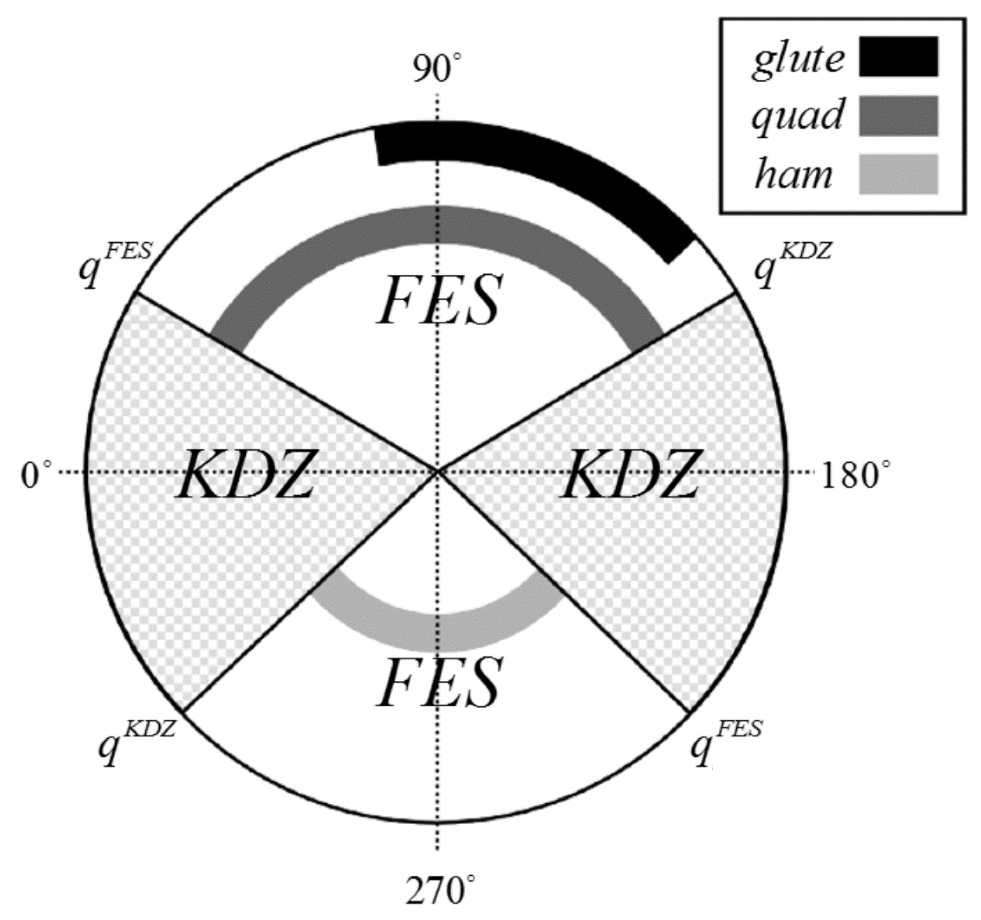
where the unknown, nonlinear individual muscle control effectiveness mapping the FES input to the muscle torque output is denoted by b m : Q × R R > 0 and the piecewise right-continuous switching signal for activating individual muscle groups is denoted by σ m : Q 0 , 1 , m M , where the set M includes the right (R) and left (L) quadriceps femoris (Q), hamstring (H) and gluteal (G) muscle groups (i.e., the stimulated muscle groups). The switching signal was triggered based on the crank’s position such that each muscle, when stimulated, contributed a non-negligible amount of torque to propel the crank forward (interested readers may refer to [15] for additional details on the design and implementation of the switching signal). The combination of all stimulation regions is referred to as the FES region, and the remainder of the crank cycle is referred to as the kinematic dead zone (KDZ). The KDZ was present in the regions of the crank where it was kinematically inefficient to stimulate a muscle and thus no muscle stimulation was applied. Figure 3 provides a visual representation of the FES region and KDZ. In Equation (3), the subsequently designed muscle control input is used across all muscle groups and denoted by u h : R t 0 R .
In Equation (1), the inertial, centripetal–Coriolis and gravitational effects of the combined cycle-rider system are denoted by M : Q R , C : Q × R R , and G : Q R , respectively. The rider’s passive viscoelastic tissue torques and the cycle’s friction are denoted by P : Q × R R and b R > 0 , respectively, while the system disturbances are denoted by d : R t 0 R . The Euler Lagrange dynamics in Equation (1) are developed and explained in detail in [57]. The passive–viscous tissue forces and muscle dynamics are modeled using the experimental and simulation results in [50,59,60,61] that applied neuromuscular electrical stimulation to lower-limb muscles. The cycle–rider dynamics were used to inform the control design and develop the stability analysis. However, explicit knowledge of the dynamics was not exploited or required to design and implement the robust and learning controllers discussed in the subsequent section.

3. Results

Compared to traditional human–robot interaction, FES cycling diverges significantly because both the human and the robot must be controlled during the interaction (as opposed to only controlling the robot). Because two systems must be actuated (i.e., the cycle’s electric motor and the rider’s muscles), two controllers must be designed and simultaneously implemented. Controllers are predicated on the tracking objectives (e.g., cadence tracking and torque tracking) that define the desired behavior of the system; tracking objectives are then described in terms of error systems.
In the following, an overview of the authors’ previous results on FES cycling is presented [15,16,17,18,19,20]. Sections are divided by tracking objectives:(1) cadence control, where the cycle and rider have a shared tracking objective [15,16]; (2) direct torque control, where the cycle and rider have separate tracking objectives [17,18]; and (3) indirect torque control, where the cycle and rider have coupled tracking objectives [19,20]. Within each section (i.e., for each tracking objective), the results are further divided into robust [15,17,19] and adaptive control [16,18,20]. For each result, sample experimental results are provided to highlight various measures and metrics including average tracking errors and standard deviations.

3.1. Cadence Control

When actuating the FES cycle under a cadence control paradigm, the cycle’s motor and the rider’s muscles work together to accomplish a shared tracking objective; i.e., keeping the cycle’s crank rotating at a desired cadence. The cadence tracking objective is described by the tracking error e : R t 0 R and the auxiliary, or filtered, tracking error r : R t 0 R , respectively, defined as
e ( t ) q d ( t ) q ( t ) ,
r ( t ) e ˙ ( t ) + α e ( t ) ,
where q d : R t 0 R denotes the twice-differentiable desired position trajectory and α R > 0 denotes a selectable constant control gain. The two error systems can then be combined in a composite error system z : R t 0 R 2 defined as
z ( t ) e ( t ) r ( t ) T .
The following results use both error systems described in Equations (4) and (5). The first cadence tracking result provides a robust control approach [15], while the second result leverages an adaptive learning-based controller [16]. For these controllers, the rider’s muscles were stimulated in the FES region and the cycle’s motor was activated in the KDZ. Between the rider’s muscles and the cycle’s motor, seven actuators were engaged and disengaged within approximately 1.2 s of each other (i.e., approximately one crank cycle at 50 RPM).

3.1.1. Robust Cadence Control

For cadence control, the cycle’s motor and rider’s muscles work together to keep the cycle’s crank rotating at a constant cadence. Because there is a single objective, the same controller can be implemented on both the cycle’s motor and rider’s muscles. Depending on whether the crank is in the FES region or the KDZ, the control input can be redirected to the rider’s muscles or cycle’s motor, respectively, through the use of an appropriately designed switching signal. For the result in [15], the control inputs to the cycle’s motor and the rider’s muscles were designed as
u e ( t ) = k e σ e u ( t ) ,
u h ( t ) = k h u ( t ) ,
where k e R > 0 denotes a constant motor control gain, σ e : Q 0 , 1 denotes a motor switching signal which is activated in the KDZ and k h R > 0 denotes a constant muscle control gain. In Equations (7) and (8), u : R t 0 R denotes the shared cadence controller, defined as
u t   = k 1 r t + k 2 + k 3 z t + k 4 z t 2 sgn r t ,
where k i R > 0 , i 1 , , 4 denote constant control gains, · denotes a Euclidean norm and sgn ( · ) denotes the signum function. A block diagram of robust cadence control is shown in Figure 4.
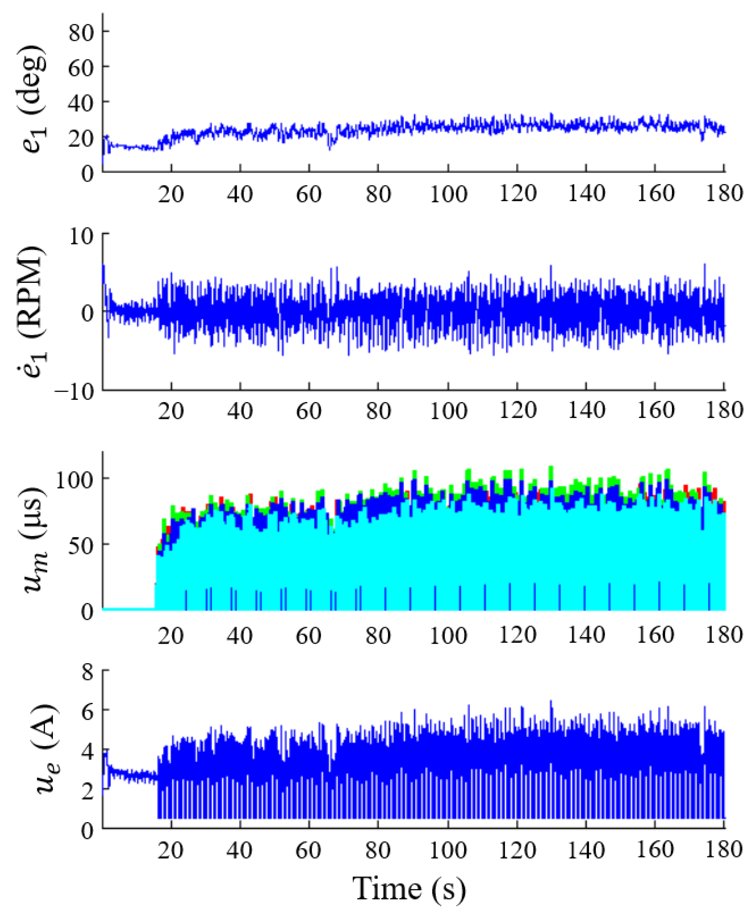
The philosophy behind the control design in Equation (9) is to use high-frequency feedback to stabilize the system and compensate for the uncertainties/disturbances in the cycle–rider system. The robust cadence controller in Equation (9) was implemented and tested in cycling experiments with five able-bodied individuals who were instructed to provide no volition, remain passive and were blind to the objective and results. Their average tracking results are presented in Table 1, and a sample result is presented in Figure 5. To illustrate system stability, a Lyapunov-like switched system stability assessment was conducted [15].

3.1.2. Adaptive Cadence Control

Repetitive learning control is a non-parametric adaptive approach designed to estimate and compensate for, the desired periodic dynamics resulting from cycling. The rationale behind this approach is that by accurately estimating the periodic dynamics, tracking errors can be reduced. A repetitive learning controller exploits inputs from past trials or iterations to improve tracking performance. However, due to uncertainties and disturbances, which are non-periodic in the cycle-rider system, additional robust control terms are needed to ensure stability. Therefore, the learning control component acts as a feedforward input that can be added to a robust cadence controller to compensate for the periodic and non-periodic dynamics of cycling [16]. By adding the learning component to the cadence controller, the effects of high-gain and high-frequency control terms can be reduced, decreasing chattering and lowering the stimulation magnitudes, which are theorized to contribute to accelerated muscle fatigue.
In [16], the control inputs to the cycle’s motor and rider’s muscles were the same as in Equations (7) and (8), but instead of using the robust cadence controller in Equation (9), the repetitive learning controller was developed as
u t = W ^ d t + k 1 r t + k 2 ρ 2 z t r t + k 3 + k 4 W ^ d t sgn r t ,
where k i R > 0 , i 1 , , 4 denote constant control gains, ρ · R is a known, positive, radially unbounded, nondecreasing function and W ^ d : R t 0 R is the repetitive control law. The repetitive control law is designed and updated as
W d ^ ( t ) = sat β r ( W ^ d ( t T ) ) + μ r ( t ) ,
where sat β r ( · ) is the saturation function, β r R is a positive bounding constant, μ R > 0 is a positive control gain and T R is the known period. The saturation function outputs a value equal to its input if the magnitude of the input is less than or equal to the positive constant β r R . Alternatively, the saturation function outputs the product of β r R and the sign of the input if the magnitude of the input is greater than β r R . The learning-based cadence tracking controller in [16] uses a single adaptive update law that stores the muscle and motor inputs in a single buffer and requires the selection of a single constant learning gain. A sample experiment implementing the learning controller is presented in Figure 6. In this tracking result, the muscle groups and the electric motor exploit the learning controller in the FES region and KDZ region, respectively. In [16], a total of five able-bodied participants and three participants with neurological injuries were included, and their average tracking results are presented in Table 1.

3.2. Direct Torque Control

Power (i.e., torque) tracking is another desirable objective because a high power output can help to prevent muscle atrophy, increase cardiovascular parameters and provide additional health benefits [62,63,64,65,66,67]. Because power is the product of torque and speed ( P = τ q ˙ ), by successfully tracking a desired torque and speed, a desired power can also be achieved ( P d = τ d q ˙ d ). The torque tracking objective ensures that the estimated torque about the crank shaft produced by stimulating the rider’s muscles, denoted by τ ^ a : R t 0 R , tracks the desired torque τ d : R t 0 R . To facilitate the analyses, the torque tracking objective was nested within a integral, denoted by e τ : R t 0 R and defined as
e τ ( t ) t c t τ d ( ψ ) τ ^ a ( ψ ) d ψ ,
where t c R 0 represents the time of controller activation. To quantify the cadence tracking objective, the error systems introduced in Equations (4)–(6) are used. The following results from [17,18] highlight strategies for robust and learning-based control algorithms for direct torque control, respectively.

3.2.1. Robust Direct Torque Control

To accomplish simultaneous cadence and torque control, each of these objectives must be assigned to either the cycle’s motor or the rider’s muscles. While the result in [17] showcases various possible assignments, the most successful strategy used the cycle’s motor to regulate the cadence of the cycle–rider system and the rider’s muscles to track instantaneous torque. Unlike the previous results presented on cadence tracking, due to the two unique tracking objectives, two unique controllers were implemented. The controllers for the cycle’s motor and rider’s muscles were respectively designed as [17]
u e ( t ) = k 1 r ( t ) + k 2 + k 3 z ( t ) + k 4 z ( t ) 2 + k 5 u h ( t ) sgn ( r ( t ) ) ,
u h ( t ) = k 6 e τ ( t ) + k 7 sgn ( e τ ( t ) ) ,
where k i R > 0 , i 1 , , 7 denote constant control gains. While the cycle’s motor was always active (i.e., in the FES region and the KDZ), the rider’s muscles were only stimulated in the FES region of the crank cycle. A block diagram of robust direct torque control is shown in Figure 7.
As shown in Equation (13), because the cycle’s motor was regulating the cadence of the system, it was designed to compensate for the torque from the rider. Using a Lyapunov-based stability analysis, it was then shown that the cadence error system was always globally exponentially stable [17]. Conversely, because the rider’s muscles were not activated at all times, a dwell-time analysis was required for the torque error system. By selecting appropriate gain conditions, it was then shown that the torque error system was always uniformly ultimately bounded [17]. An illustrative result is depicted in Figure 8. A total of seven able-bodied participants and six participants with neurological injuries were included in this result, and their average tracking results are presented in Table 1.

3.2.2. Adaptive Direct Torque Control

Instead of using a high-frequency robust controller, the result in [18] uses an adaptive approach for direct torque tracking. Specifically, a learning-based torque controller is designed for the rider’s muscles to track a state-periodic desired torque trajectory. The desired torque is designed as a modified function of the knee joint torque transfer ratio [15], which is a function of the crank position (thus termed as spatially periodic because the crank cycle resets every 2 π radians). The muscle spatial learning controller is updated using the crank angle and inputs from past crank cycles. As with the previous result for robust direct torque tracking [17], the cycle’s motor achieves cadence tracking using a robust controller. The stability analysis of the learning-based torque controller and robust cadence controller uses passivity theory. For a passive system, the energy supplied to a system is greater than or equal to the energy stored by the system (quantified by a storage function) over a certain time interval [28,68]. The rest of the energy is dissipated because a passive system cannot generate energy on its own. By virtue of passivity, the electric motor complies with the muscle torque output instead of rejecting it. The controllers for the cycle’s motor and rider’s muscles were respectively designed as [18]
u e = ( k 1 + 1 ) r ( k 2 + k 3 ρ ( z ) z ) sgn ( r ) ,
u h = k 4 e τ + ( k 5 + 1 ) W ^ d ,
where k i R > 0 , i 1 , , 5 denote positive constant control gains and W ^ d : R t 0 R is the repetitive learning input, which is defined and updated as
W ^ d ( t ) = Γ sat β r ( W ^ d ( t T ) ) + k L e τ ( t ) ,
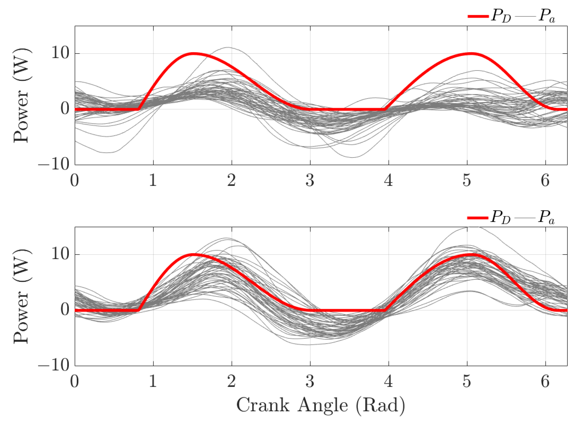
where Γ ( 0 , 1 ] is a selectable constant, sat β r ( · ) is the saturation function, β r R is a positive saturation threshold and k L is a positive constant learning gain. The saturation function is described above in the paragraph following Equation (11). The cycle’s cadence tracking controller was always active (i.e., in the FES region and the KDZ) and the rider’s muscles (i.e., torque controller) were only stimulated in the FES region of the crank cycle. The implementable form of Equation (17) requires a mapping between time and space, which exists because the crank position q is a strictly increasing function of time (i.e., q = f ( t ) is analytic and its inverse exists globally). Thus, any function of time can be expressed as a function of the state q. An experiment of the adaptive direct tracking result is illustrated in Figure 9. In this result, the performance of the controller is quantified by the mismatch between the desired power (i.e., the product of the desired speed and torque) and active power (i.e., the product of the actual cadence and the active torque produced by the muscles). A total of five able-bodied participants and three participants with neurological injuries were included in this result, and their average tracking results are presented in Table 1.

3.3. Indirect Torque Control

Instead of directly tracking torque using a torque-based error system as in Equation (12) for feedback [17,18], the torque error can instead be transformed to a new, modified cadence trajectory using admittance control. In this control paradigm, an admittance filter is employed in an outer-loop of the controller to modify the desired cadence trajectory before being tracked with an inner-loop position controller. By assigning the cycle’s motor the objective of tracking this admitted trajectory, it is indirectly tasked with tracking the desired torque. The admittance filter was designed as
τ i n t ( t ) τ d ( t ) M d q ¨ a ( t ) + B d q ˙ a ( t ) ,
where τ d : R t 0 R denotes the desired interaction torque between the cycle and rider; τ i n t : R t 0 R denotes the measurable interaction torque; q ˙ a , q ¨ a : R t 0 R denote the admitted velocity and acceleration, respectively; and M d , B d R > 0 denote the desired inertia and damping, respectively. The input to the filter is a torque error defined as e τ τ i n t τ d (redefined from Equation (12)) and the output is the admitted trajectory q a , q ˙ a , q ¨ a . The inner-loop position controller tracks the admittance error system quantified by ξ : R t 0 R and ψ : R t 0 R , defined as
ξ ( t ) q a ( t ) + q d ( t ) q ( t ) ,
ψ ( t ) ξ ˙ ( t ) + β ξ ( t ) ,
where β R > 0 denotes a selectable constant control gain. The two error systems can then be combined in a composite error system ζ : R t 0 R 2 defined as
ζ ( t ) ξ ( t ) ψ ( t ) T .
Thus, if the cycle’s motor can regulate the errors in Equations (19) and (20), the cycle’s motor can be used for the indirect torque tracking objective. Simultaneously, as in Section 3.1, the rider’s muscles can be used for the cadence tracking objective. For simultaneous cadence and indirect torque tracking, the following two results use the cadence error systems in Equations (4)–(6) and the admittance error systems in Equations (18)–(21).

3.3.1. Robust Indirect Torque Control

By comparing the cadence error system in Equations (4) and (5) to the admittance error system in Equations (19) and (20), it can be seen that, although they are unique, they are also coupled. Because both systems are predicated on position errors, they are unable to simultaneously converge to zero, unless the torque error in Equation (18) is always zero. Therefore, one error system must be designated as the dominant or convergent error system. For the result in [19], the cadence error system was prioritized, selected as the dominant system and assigned to the rider’s muscles. Both the cycle’s motor and the rider’s muscles were actuated using robust controllers designed as [19]
u e t = k 1 ψ t + k 2 + k 3 ϕ t + k 4 ϕ t 2 sgn ψ t ,
u h t = k 5 r t + k 6 + k 7 z t + k 8 z t 2 + k 9 u e t sgn r t ,
where k i R > 0 , i 1 , , 9 denote constant control gains and the vector ϕ : R t 0 R 4 is defined as ϕ ζ ( t ) T , q ˙ a ( t ) , q ¨ a ( t ) T . A block diagram of robust indirect torque control is shown in Figure 10.
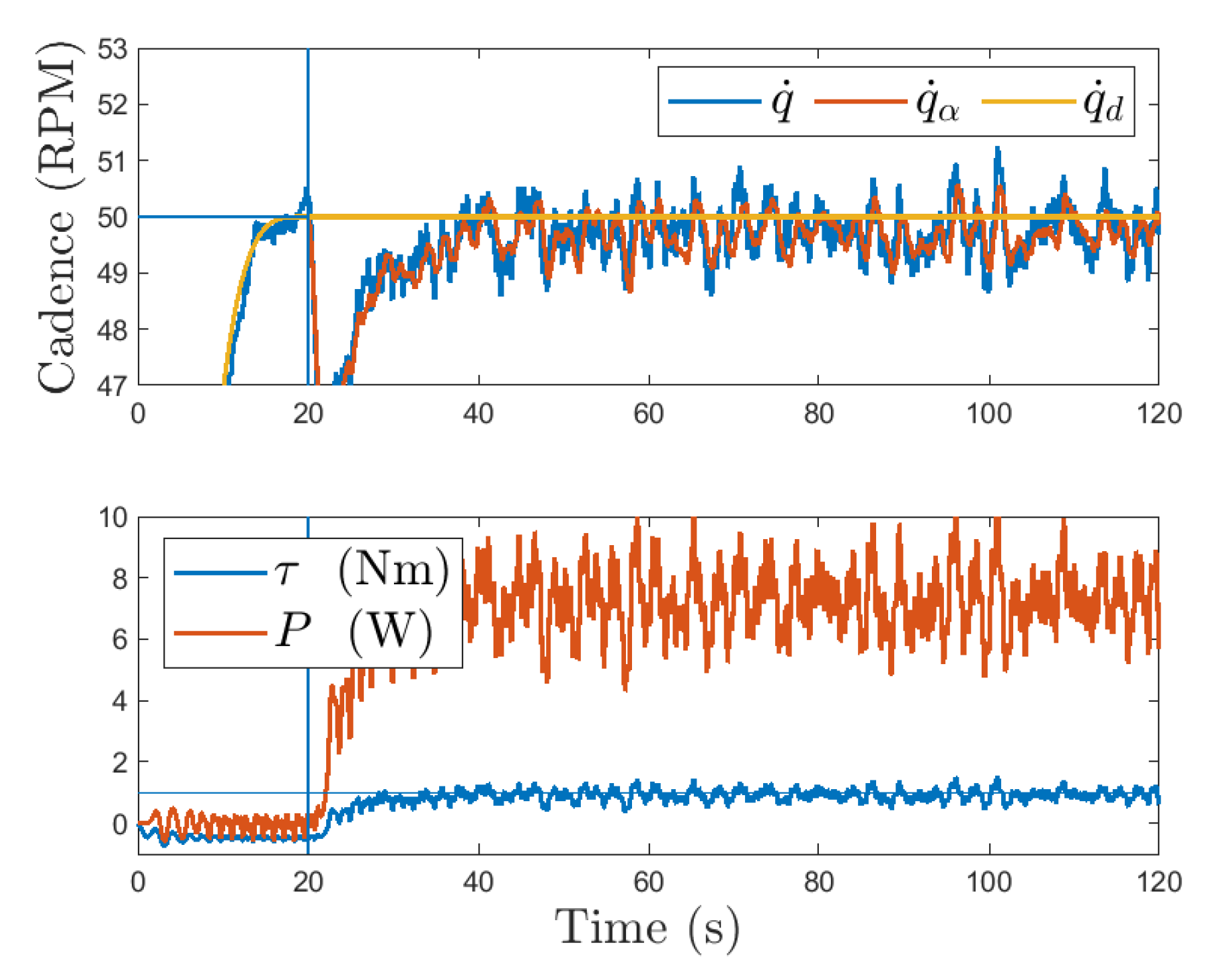
As seen in Equation (23), the rider’s muscle controller is designed to compensate for the motor’s torque by cancelling out the motor’s control input. According to the stability analysis in [19], this combination of controllers renders the admittance error system always passive and the cadence error system exponentially stable in the FES regions. An illustrative result from a participant with spina bifida is depicted in Figure 11. In [19], a total of three able-bodied participants and four participants with neurological injuries were included, and their average tracking results are presented in Table 1. Another feature of this result is that it includes a demonstration of the rider volitionally contributing to the pedaling task. It is also noted that volitional contributions do not destabilize the error systems but still guarantee tracking performance. Using admittance control, the behavior between the cycle and rider was more compliant than in direct torque tracking. Because of the inherent compliance (modifiable based on the selected admittance parameters), admittance control is viewed as an assist-as-needed control paradigm.

3.3.2. Adaptive Indirect Torque Control

Compared to [19], a more recent result in [20] was obtained by equipping the FES cycle with an adaptive indirect torque controller (i.e., admittance controller). Moreover, this result is unique because the controllers were employed on the split-crank FES cycle described in Section 2, as opposed to the single-crank cycle in [19]. By utilizing the split-crank cycle, a variety of highly-customizable trajectories can be investigated between the right and left sides of the cycle–rider system. The adaptive component of the controller was implemented on the cycle’s motor and therefore selected as the convergent or dominant error system. Furthermore, the adaptive component was trained using a gradient-descent algorithm, as opposed to a repetitive learning controller [18]. Lastly, the muscle controller was saturated in the control design, instead of solely in experiments, leading to a more rigorous stability analysis. The motor and muscle controllers were designed as [20]
u h t = sat ρ k 1 r t + k 2 + k 3 z t + k 4 z t 2 sgn r t ,
u e t = Y ( q ˙ d , q ¨ d , t ) θ ^ ( t ) + k 5 ψ t + k 6 + k 7 ϕ t + k 8 u h t sgn ψ t ,
where sat ρ · denotes the saturation function with saturation limit ρ R > 0 , k i R > 0 , i 1 , , 8 denote constant control gains, Y : R 2 × R 0 R 1 × 8 denotes a computable regression matrix and θ ^ : R 0 R 8 × 1 denotes a time-varying estimate of the constant system parameters [20]. The estimates for the system parameters in Equation (25) were generated on-line according to
θ ^ ˙ ( t ) = proj Γ Y ( t ) T ψ ( t ) ,
where Γ R 8 × 8 denotes a constant positive definite learning gain and proj · denotes a projection algorithm operator ([69] Appendix E).
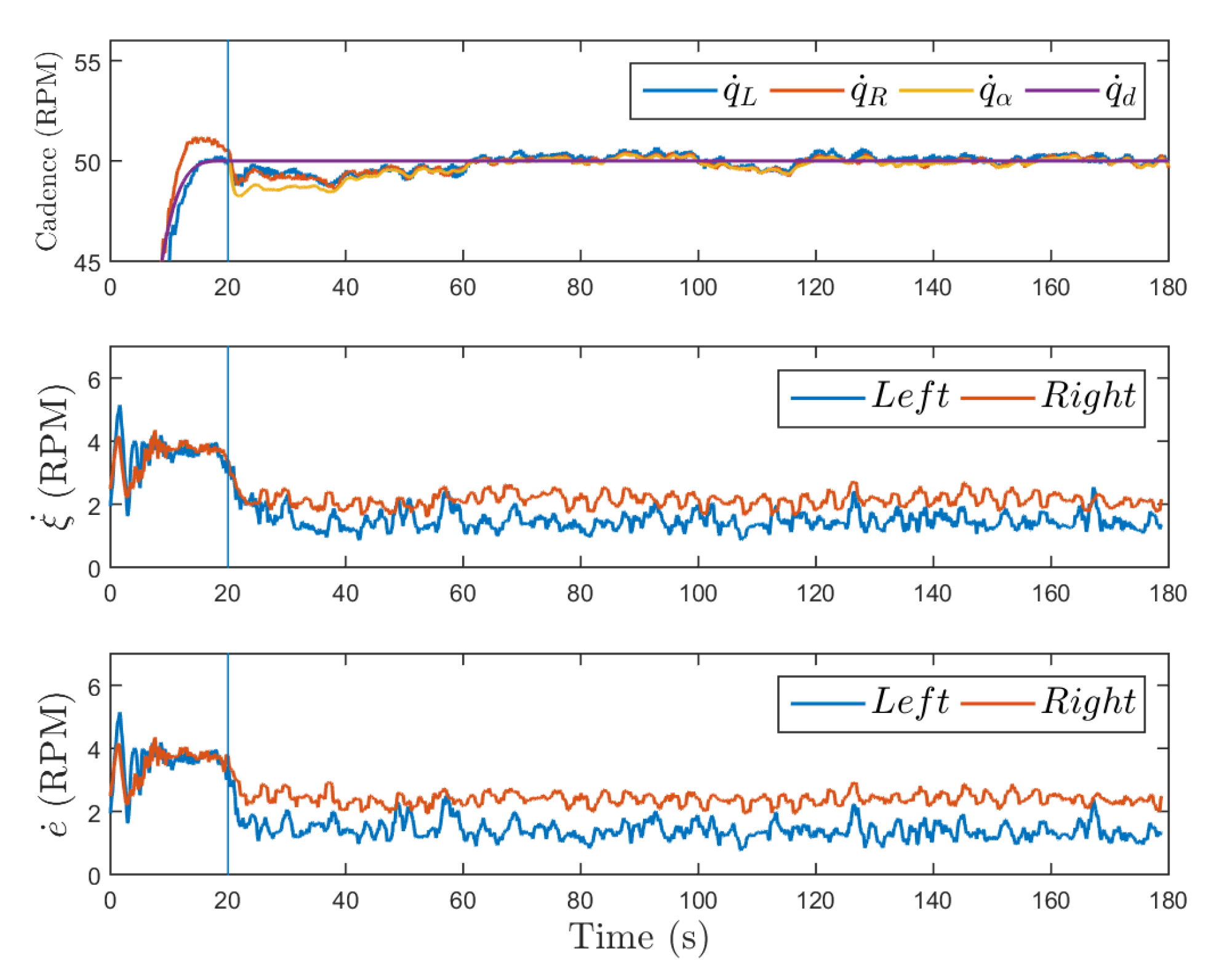
As indicated in Equation (25), the motor’s controller is designed to compensate for the torque originating from the rider; this is done to promote the convergence of the adaptive estimates of the system parameters. According to the stability analysis in [20], the admittance controller globally asymptotically regulates the admittance error system and the position error system is passive for all time. Figure 12 shows a result for a participant with Parkinson’s disease using the adaptive indirect torque controller. A total of one able-bodied participant and three participants with neurological injuries were included in this result, and their average tracking results are presented in Table 1. Using the adaptive controller on the split-crank cycle, errors were successfully brought closer to zero than when using a robust controller on the same cycle, indicating an increase in cycling performance. Additionally, the standard deviation of the cycle’s cadence was reduced, resulting in a smoother pedaling experience for the rider.

4. Discussion

As presented in Section 3, there are numerous options for controlling the operation of FES cycles. The aforementioned studies include cadence control [15,16], direct torque control [17,18] and indirect torque control via admittance control [19,20]. To select the most appropriate strategy, one must consider a number of factors including the type of sensors available for feedback, rehabilitation objectives and the rider’s capabilities. Selecting the most appropriate controller and FES cycle is determined by numerous factors, but at minimum, the authors would recommend taking advantage of all sensors available. For example, if there is a torque sensor available, it should not only record data but also be used in feedback. Moreover, by measuring the interaction torque between the cycle and rider, additional safety measures can be implemented to limit the maximum allowable forces between the cycle and rider. By tracking torque in addition to cadence, more rehabilitative outcomes can be achieved.
The aforementioned controllers can be divided into robust and adaptive categories. While adaptive controllers do offer the promise of improved performance and reduced tracking errors (particularly on the split-crank cycle), they can significantly increase the complexity of the control design and stability analysis. The authors would refer interested readers to the references cited above for specific details on controller implementation (e.g., to compare a repetitive learning algorithm to a gradient descent algorithm). Depending on the complexity of the controller, gains may also require extensive tuning time; this time may result in prolonged experiments and early fatigue. Therefore, in implementation, one must consider the benefits of increased cycling performance at the expense of complexity.
When comparing direct to indirect torque tracking, several factors need consideration; namely, in direct torque control, the motor should be used to regulate the cycle’s cadence and the rider’s muscles used to regulate the torque production. Conversely, in indirect torque tracking, we would recommend that the motor be used to regulate the interaction torque between the cycle and rider, and the rider should be responsible for keeping the cycle at the desired cadence. Details are available in Table 1. Because admittance control uses an inner-loop position controller, it can be viewed as an assist-as-needed control paradigm and used to support the rider in their cadence tracking objective. When the rider is tasked with keeping the cycle at the desired cadence, and because the rider’s muscles are not activated at all times, it is expected that the cadence error would be larger than when the motor is used to regulate cadence (compare [19,20] to [15,16,17,18] in Table 1). Additionally, because the cycle is tracking torque indirectly, it is anticipated that the torque error would be larger than the direct torque tracking approach (compare [17,18] to [19,20]) on Table 1. Despite the larger tracking errors, the cycle exhibits compliant behavior compared to the other approaches and accommodates the rider’s capabilities, rather than rejecting them.
Additionally, in the direct torque tracking approach, the desired torque in Table 1 is the desired torque produced by the rider, not the desired interaction torque, as in the indirect torque tracking approach. The difference is that, in [17,18], a measurement of the passive torque required to actuate the rider’s body is taken and then subtracted from the measured torque. This increases the complexity of the approach and requires a pretrial to obtain this value but provides a more accurate measurement of the rider’s net torque production. In comparison, in [19,20], the authors were instead concerned about the interaction torque between the cycle and rider, resulting in a simplified approach.
Regardless of the selected tracking objective and controller, as in any human–robot interaction task, the safety of the human must be the highest priority, particularly for individuals with neurological injuries or movement impairments. To guarantee appropriate system behavior, any controller developed for human–robot interaction should be accompanied with a rigorous stability analysis. FES cycling is inherently a nonlinear, unknown and uncertain dynamical system, and it requires nonlinear control techniques for analysis [28]. Furthermore, because FES cycling involves discrete switching between different muscle groups, and in some cases the cycle’s motor, it should also be analyzed for stability using switched systems tools [70]. The controllers referenced in Section 3 are all accompanied with rigorous Lyapunov and/or passivity-based switched systems stability analysis [15,16,17,18,19,20].
Control design methods are needed to compensate for the time-varying muscle input delay (i.e., the delay between the application of NMES and muscle contraction). The electromechanical input delay affects the rate of muscle force production, and thus cycling tracking performance is potentially compromised. For example, the input delay requires modifying the muscle stimulation patterns (or FES regions) by a phase shift to generate muscle force earlier in the crank cycle and prevent inadvertent tracking error accumulation [15]. Future work will seek to incorporate a time-varying estimate of the input delay during FES cycling using adaptive-based control methods.
The intersection between FES cycling and teleoperation is an emerging research area. A challenge in teleoperated systems is to guarantee that the control inputs, kinematic trajectories and interaction torques between the coupled robotic systems (i.e., leader and follower) remain bounded in the presence of human input. Teleoperated robotic systems for FES cycling facilitate the development of home-based training programs in which therapists can remotely adjust cycling parameters (e.g., the cycle’s load or target cadence) using an input device that directly influences the cycling performance of the rider. FES cycling programs that are supervised and adapted by therapists could further accelerate the adoption of FES cycles at home and increase rider engagement during exercise. These results offer new and exciting inroads to FES cycling, as well as maturing the field of rehabilitation to applications such as telemedicine.
Potential future works include overlaying augmented and virtual reality (AR/VR) with closed-loop FES cycling. AR/VR is designed to more completely immerse the rider in a holistic cycling experience engaging both the body and the mind. AR/VR may also encourage an individual to participate in a regular rehabilitation or training regimen by implementing game-like features. An open challenge related to the coupling of AR/VR technologies with FES cycling is to determine how to map changes in physical variables such as torque and cadence to intuitive visual stimuli that boost the rider’s cycling performance. Additional future works include the possibility of controlling the system with biological signals such as electroencephalography (EEG). The incorporation of biological signals as control signals could offer individuals suffering from paresis or paralysis a whole new level of independence in their rehabilitation or training regimes. This brain–computer interface is commonly referred to as brain–computer interaction (BCI) [71]. Additionally, more investigation is warranted for studies that not only accommodate but encourage the human’s volitional contributions.

5. Conclusions

The variety of controllers, objectives and FES cycles presented in this article offer promising insights into rehabilitation and human–robot interaction. The developed control algorithms can be translated to clinical settings by matching primary outcome measures with the tracking objectives and control methods described in this article. For example, if a study’s primary goal is to reduce muscle spasticity, it is recommended to use a testbed that monitors changes in the leg resistance during cycling (i.e., torque feedback) and implement a control algorithm that adjusts the torque or resistance experienced by the rider as needed. Alternatively, if the main goal is to increase cardiorespiratory output, implementing a control algorithm that guarantees satisfactory performance at sufficiently large cadences is advisable. Autonomous rehabilitation systems developed to provide assistance for people with movement impairments have the potential to improve functional outcomes and overall quality of life. In addition, FES activates paralyzed muscles and contributes to restoring neuromuscular control. The synergy between FES and robotic machines (e.g., motorized cycles and powered lower-limb exoskeletons) is capable of balancing competing goals such as maximizing the active muscle torque, exercise duration and task intensity. Lastly, to ensure user safety and maximize rehabilitative benefits, these therapies should accommodate and encourage user participation while guaranteeing stable motion and performance.

Author Contributions

Conceptualization, C.C., V.D. and W.D.; methodology, C.C. and V.D.; writing—original draft preparation, C.C. and V.D.; writing—review and editing, W.D.; visualization, C.C., V.D. and W.D.; funding acquisition, W.D. All authors have read and agreed to the published version of the manuscript.

Funding

This research is supported in part by NSF award number 1762829. Any opinions, findings and conclusions or recommendations expressed in this material are those of the authors and do not necessarily reflect the views of the sponsoring agency.

Institutional Review Board Statement

The study was conducted according to the guidelines of the Declaration of Helsinki and approved by the Institutional Review Board of the University of Florida protocol code IRB201901676.

Informed Consent Statement

Informed consent was obtained from all subjects involved in the study.

Data Availability Statement

The data presented in this study are available on request from the corresponding author. The data are not publicly available due to IEEE copyright policy.

Conflicts of Interest

The authors declare no conflict of interest. The funders had no role in the design of the study; in the collection, analyses, or interpretation of data; in the writing of the manuscript, or in the decision to publish the results.

References

  1. Wallace, S.E.; Kimbarow, M.L. Cognitive Communication Disorders; Plural Publishing: San Diego, CA, USA, 2016; pp. 253–277. [Google Scholar]
  2. Benjamin, E.J.; Blaha, M.J.; Chiuve, S.E.; Cushman, M.; Das, S.R.; Deo, R.; de Ferranti, S.D.; Floyd, J.; Fornage, M.; Gilleespie, C.; et al. Heart disease and stroke statistics—2017 update. Circulation 2017, 135, 146–603. [Google Scholar] [CrossRef]
  3. National Spinal Cord Injury Statistical Center. Spinal Cord Injury Facts and Figures at a Glance. J. Spinal Cord Med. 2012, 35, 197–198. [Google Scholar] [CrossRef]
  4. Ho, C.H.; Triolo, R.J.; Elias, A.L.; Kilgore, K.L.; DiMarco, A.F.; Bogie, K.; Vette, A.H.; Audu, M.L.; Kobetic, R.; Chang, S.R.; et al. Functional Electrical Stimulation and Spinal Cord Injury. Phys. Med. Rehabil. Clin. N. Am. 2014, 25, 631–654. [Google Scholar] [CrossRef] [Green Version]
  5. Lynch, C.; Popovic, M. Functional Electrical Stimulation. IEEE Control Syst. Mag. 2008, 28, 40–50. [Google Scholar]
  6. Peckham, P.H.; Knutson, J.S. Functional electrical stimulation for neuromuscular applications. Annu. Rev. Biomed. Eng. 2005, 7, 327–360. [Google Scholar] [CrossRef]
  7. Edgerton, V.R.; de Leon, R.D.; Harkema, S.J.; Hodgson, J.A.; London, N.; Reinkensmeyer, D.J.; Roy, R.R.; Talmadge, R.J.; Tillakaratne, N.J.; Timoszyk, W.; et al. Retraining the injured spinal cord. J. Physiol. 2001, 533, 15–22. [Google Scholar] [CrossRef]
  8. Edgerton, V.; Roy, R.R. Paralysis recovery in humans and model systems. Curr. Opin. Neurobiol. 2002, 12, 658–667. [Google Scholar] [CrossRef]
  9. Jones, M.L.; Evans, N.; Tefertiller, C.; Backus, D.; Sweatman, M.; Tansey, K.; Morrison, S. Activity-Based Therapy for Recovery of Walking in Individuals With Chronic Spinal Cord Injury: Results From a Randomized Clinical Trial. Arch. Phys. Med. Rehabil. 2014, 95, 2239–2246. [Google Scholar] [CrossRef]
  10. Peng, C.W.; Chen, S.C.; Lai, C.H.; Chen, C.J.; Chen, C.C.; Mizrahi, J.; Handa, Y. Review: Clinical Benefits of Functional Electrical Stimulation Cycling Exercise for Subjects with Central Neurological Impairments. J. Med. Biol. Eng. 2011, 31, 1–11. [Google Scholar] [CrossRef]
  11. Harrington, A.T.; McRae, C.G.A.; Lee, S.C.K. Evaluation of functional electrical stimulation to assist cycling in four adolescents with spastic cerebral palsy. J. Pediatr. 2012, 2012, 1–11. [Google Scholar] [CrossRef]
  12. Griffin, L.; Decker, M.; Hwang, J.; Wang, B.; Kitchen, K.; Ding, Z.; Ivy, J. Functional electrical stimulation cycling improves body composition, metabolic and neural factors in persons with spinal cord injury. J. Electromyogr. Kinesiol. 2009, 19, 614–622. [Google Scholar] [CrossRef] [PubMed]
  13. Berry, H.R.; Perret, C.; Saunders, B.A.; Kakebeeke, T.H.; Donaldson, N.D.N.; Allan, D.B.; Hunt, K.J. Cardiorespiratory and Power Adaptation to Stimulated Cycle Training in Paraplegia. Med. Sci. Sports Exerc. 2008, 40, 1573–1580. [Google Scholar] [CrossRef]
  14. Hunt, K.J.; Stone, B.; Negård, N.O.; Schauer, T.; Fraser, M.H.; Cathcart, A.J.; Ferrario, C.; Ward, S.A.; Grant, S. Control Strategies for Integration of Electric Motor Assist and Functional Electrical Stimulation in Paraplegic Cycling: Utility for Exercise Testing and Mobile Cycling. IEEE Trans. Neural Syst. Rehabil. Eng. 2004, 12, 89–101. [Google Scholar] [CrossRef] [Green Version]
  15. Bellman, M.J.; Downey, R.J.; Parikh, A.; Dixon, W.E. Automatic Control of Cycling Induced by Functional Electrical Stimulation with Electric Motor Assistance. IEEE Trans. Autom. Sci. Eng. 2017, 14, 1225–1234. [Google Scholar] [CrossRef]
  16. Duenas, V.H.; Cousin, C.A.; Parikh, A.; Freeborn, P.; Fox, E.J.; Dixon, W.E. Motorized and Functional Electrical Stimulation Induced Cycling via Switched Repetitive Learning Control. IEEE Trans. Control Syst. Technol. 2019, 27, 1468–1479. [Google Scholar] [CrossRef]
  17. Cousin, C.A.; Duenas, V.; Rouse, C.; Bellman, M.; Freeborn, P.; Fox, E.; Dixon, W.E. Closed-Loop Cadence and Instantaneous Power Control on a Motorized Functional Electrical Stimulation Cycle. IEEE Trans. Control Syst. Technol. 2019, 28, 2276–2291. [Google Scholar] [CrossRef]
  18. Duenas, V.; Cousin, C.A.; Ghanbari, V.; Fox, E.J.; Dixon, W.E. Torque and Cadence Tracking in Functional Electrical Stimulation Induced Cycling using Passivity-Based Spatial Repetitive Learning Control. Automatica 2020, 115, 108852. [Google Scholar] [CrossRef]
  19. Cousin, C.A.; Rouse, C.A.; Duenas, V.H.; Dixon, W.E. Controlling the Cadence and Admittance of a Functional Electrical Stimulation Cycle. IEEE Trans. Neural Syst. Rehabil. Eng. 2019, 27, 1181–1192. [Google Scholar] [CrossRef]
  20. Cousin, C.A.; Rouse, C.A.; Dixon, W.E. Split-Crank Functional Electrical Stimulation Cycling: An Adapting Admitting Rehabilitation Robot. IEEE Trans. Control Syst. Technol. 2020, 1–13. [Google Scholar] [CrossRef]
  21. Hogan, N. Impedance Control: An Approach to Manipulation: Part I-Theory, Part II-Implementation, Part III-Applications. J. Dyn. Syst. Meas. Control 1985, 107, 1–24. [Google Scholar] [CrossRef]
  22. Zhang, J.; Cheah, C.C. Passivity and stability of human–robot interaction control for upper-limb rehabilitation robots. IEEE Trans. Robot. 2015, 31, 233–245. [Google Scholar] [CrossRef]
  23. Li, Y.; Sam Ge, S.; Yang, C. Learning impedance control for physical robot–environment interaction. Int. J. Control 2012, 85, 182–193. [Google Scholar] [CrossRef]
  24. Li, Y.; Ge, S.S. Impedance learning for robots interacting with unknown environments. IEEE Trans. Control Syst. Technol. 2014, 22, 1422–1432. [Google Scholar] [CrossRef] [Green Version]
  25. Ranatunga, I.; Lewis, F.L.; Popa, D.O.; Tousif, S.M. Adaptive Admittance Control for Human–Robot Interaction Using Model Reference Design and Adaptive Inverse Filtering. IEEE Trans. Control Syst. Technol. 2017, 25, 278–285. [Google Scholar] [CrossRef]
  26. Anaya, F.; Thangavel, P.; Yu, H. Hybrid FES—Robotic gait rehabilitation technologies: A review on mechanical design, actuation, and control strategies. Int. J. Intell. Robot. Appl. 2018, 2, 1–28. [Google Scholar] [CrossRef]
  27. Del Ama, A.J.; Gil-Agudo, Á.; Pons, J.L.; Moreno, J.C. Hybrid FES-robot cooperative control of ambulatory gait rehabilitation exoskeleton. J. Neuroeng. Rehab. 2014, 11, 27. [Google Scholar] [CrossRef]
  28. Khalil, H.K. Nonlinear Systems, 3rd ed.; Prentice Hall: Upper Saddle River, NJ, USA, 2002. [Google Scholar]
  29. Slotine, J.J.E.; Li, W. On the adaptive control of robot manipulators. Int. J. Robot. Res. 1987, 6, 49–59. [Google Scholar] [CrossRef]
  30. Narendra, K.; Annaswamy, A. Stable Adaptive Systems; Prentice-Hall, Inc.: Englewood Cliffs, NJ, USA, 1989. [Google Scholar]
  31. Arimoto, S.; Kawamura, S.; Miyazaki, F. Bettering Operation of Dynamic Systems by Learning: A New Control Theory for Servomechanism or Mechatronics Systems. In Proceedings of the 23rd IEEE Conference on Decision and Control, Las Vegas, NV, USA, 12–14 December 1984; pp. 1064–1069. [Google Scholar]
  32. Messner, W.; Horowitz, R.; Kao, W.W.; Boals, M. A New Adaptive Learning Rule. IEEE Trans. Autom. Control 1991, 36, 188–197. [Google Scholar] [CrossRef]
  33. Reed, B. The physiology of neuromuscular electrical stimulation. Pediatr. Phys. Ther. 1997, 9, 96–102. [Google Scholar] [CrossRef]
  34. Mushahwar, V.K.; Jacobs, P.L.; Normann, R.A.; Triolo, R.J.; Kleitman, N. New Funtional Electrical Stimulation Approaches to Standing and Walking. J. Neural Eng. 2007, 4, S181–S197. [Google Scholar] [CrossRef]
  35. Kobetic, R.; To, C.S.; Schnellenberger, J.R.; Audu, M.L.; Bulea, T.C.; Gaudio, R.; Pinault, G.; Tashman, S.; Triolo, R.J. Development of hybrid orthosis for standing, walking, and stair climbing after spinal cord injury. J. Rehabil. Res. Dev. 2009, 46, 447–462. [Google Scholar] [CrossRef]
  36. Alibeji, N.A.; Molazadeh, V.; Dicianno, B.E.; Sharma, N. A Control Scheme That Uses Dynamic Postural Synergies to Coordinate a Hybrid Walking Neuroprosthesis: Theory and Experiments. Front. Neurosci. 2018, 12, 159. [Google Scholar] [CrossRef]
  37. Bo, A.; de Fonseca, L.; de Sousa, A. FES-induced co-activation of antagonist muscles for upper limb control and disturbance rejection. Med. Eng. Phys. 2016, 38, 1176–1184. [Google Scholar] [CrossRef]
  38. Doucet, B.M.; Lam, A.; Griffin, L. Neuromuscular Electrical Stimulation for Skeletal Muscle Function. Yale J. Biol. Med. 2012, 85, 201–215. [Google Scholar]
  39. Binder-Macleod, S.A.; Halden, E.E.; Jungles, K.A. Effects of stimulation intensity on the physiological responses of human motor units. Med. Sci. Sports Exerc. 1995, 27, 556–565. [Google Scholar] [CrossRef]
  40. Doucet, B.M.; Griffin, L. Maximal versus submaximal intensity stimulation with variable patterns. Muscle Nerve 2008, 37, 770–777. [Google Scholar] [CrossRef]
  41. Kebaetse, M.B.; Binder-Macleod, S.A. Strategies that improve human skeletal muscle performance during repetitive, non-isometric contractions. Pflügers Arch. 2004, 448, 525–532. [Google Scholar] [CrossRef]
  42. Karu, Z.Z.; Durfee, W.K.; Barzilai, A.M. Reducing muscle fatigue in FES applications by stimulating with N-let pulse trains. IEEE Trans. Biomed. Eng. 1995, 42, 809–817. [Google Scholar] [CrossRef] [PubMed]
  43. Popović, L.Z.; Malesevic, N.M. Muscle fatigue of quadriceps in paraplegics: Comparison between single vs. multi-pad electrode surface stimulation. In Proceedings of the 2009 Annual International Conference of the IEEE Engineering in Medicine and Biology Society, Minneapolis, MN, USA, 2–6 September 2009; pp. 6785–6788. [Google Scholar] [CrossRef]
  44. Merletti, R.; Knaflitz, M.; De Luca, C.J. Electrically evoked myoelectric signals. Crit. Rev. Biomed. Eng. 1992, 19, 293–340. [Google Scholar] [PubMed]
  45. Downey, R.; Merad, M.; Gonzalez, E.; Dixon, W. The Time-Varying Nature of Electromechanical Delay and Muscle Control Effectiveness in Response to Stimulation-Induced Fatigue. IEEE Trans. Neural Syst. Rehabil. Eng. 2017, 25, 1397–1408. [Google Scholar] [CrossRef] [PubMed]
  46. Binder-Macleod, S.A.; McLaughlin, W.A. Effects of asynchronous stimulation on the human quadriceps femoris muscle. Arch. Phys. Med. Rehabil. 1997, 78, 294–297. [Google Scholar] [CrossRef]
  47. Figoni, S.F.; Rodgers, M.M.; Glaser, R.M.; Hooker, S.P.; Feghri, P.D.; Ezenwa, B.N.; Mathews, T.; Suryaprasad, A.G.; Gupta, S.C. Physiologic responses of paraplegics and quadriplegics to passive and active leg cycle ergometry. J. Am. Paraplegia Soc. 1990, 13, 33–39. [Google Scholar] [CrossRef]
  48. Gregory, C.M.; Bickel, C.S. Recruitment Patterns in Human Skeletal Muscle During Electrical Stimulation. Phys. Ther. 2005, 85, 358–364. [Google Scholar] [CrossRef] [Green Version]
  49. Bickel, C.S.; Gregory, C.M.; Dean, J.C. Motor unit recruitment during neuromuscular electrical stimulation: A critical appraisal. Eur. J. Appl. Physiol. 2011, 111, 2399–2407. [Google Scholar] [CrossRef] [PubMed]
  50. Schauer, T.; Negård, N.O.; Previdi, F.; Hunt, K.J.; Fraser, M.H.; Ferchland, E.; Raisch, J. Online identification and nonlinear control of the electrically stimulated quadriceps muscle. Control Eng. Pract. 2005, 13, 1207–1219. [Google Scholar] [CrossRef] [Green Version]
  51. Dolbow, D.; Gorgey, A.; Ketchum, J.; Gater, D. Home-based functional electrical stimulation cycling enhances quality of life in individuals with spinal cord injury. Top. Spinal Cord Inj. Rehabil. 2013, 19, 324–329. [Google Scholar] [CrossRef] [Green Version]
  52. Ambrosini, E.; Ferrante, S.; Ferrigno, G.; Molteni, F.; Pedrocchi, A. Cycling Induced by Electrical Stimulation Improves Muscle Activation and Symmetry During Pedaling in Hemiparetic Patients. IEEE Trans. Neural Syst. Rehabil. Eng. 2012, 20, 320–330. [Google Scholar] [CrossRef] [PubMed]
  53. Ambrosini, E.; Ferrante, S.; Schauer, T.; Ferrigno, G.; Molteni, F.; Pedrocchi, A. Design of a symmetry controller for cycling induced by electrical stimulation: Preliminary results on post-acute stroke patients. Artif. Organs 2010, 34, 663–667. [Google Scholar] [CrossRef]
  54. Van der Loos, M.; Worthen-Chaudhari, L.; Schwandt, D. A Split-Crank Bicycle Ergometer Uses Servomotors to Provide Programmable Pedal Forces for Studies in Human Biomechanics. IEEE Trans. Neural Syst. Rehabil. Eng. 2010, 18, 445–452. [Google Scholar] [CrossRef]
  55. Ting, L.; Kautz, S.; Brown, D.; Zajac, F. Contralateral movement and extensor force generation alter flexion phase muscle coordination in pedaling. J. Neurophysiol. 2000, 83, 3351–3365. [Google Scholar] [CrossRef] [PubMed]
  56. Elmer, S.J.; McDaniel, J.; Martin, J.C. Biomechanics of counterweighted one-legged cycling. J. Appl. Biomech. 2016, 32, 78–85. [Google Scholar] [CrossRef]
  57. Bellman, M. Control of Cycling Induced by Functional Electrical Stimulation: A Switched Systems Theory Approach. Ph.D. Thesis, University of Florida, Gainesville, FL, USA, 2015. [Google Scholar]
  58. Idsø, E.S. Development of a Mathematical Model of a Rider-Tricycle System; Technical Report; Department of Engineering Cybernetics, Norwegian University of Science and Technology: Trondheim, Norway, 2002. [Google Scholar]
  59. Ferrarin, M.; Pedotti, A. The Relationship Between Electrical Stimulus and Joint Torque: A Dynamic Model. IEEE Trans. Rehabil. Eng. 2000, 8, 342–352. [Google Scholar] [CrossRef]
  60. Ferrarin, M.; Palazzo, F.; Riener, R.; Quintern, J. Model-Based Control of FES-Induced Single Joint Movements. IEEE Trans. Neural Syst. Rehabil. Eng. 2001, 9, 245–256. [Google Scholar] [CrossRef]
  61. Riener, R.; Ferrarin, F.; Pavan, E.E.; Frigo, C.A. Patient-Driven Control of FES-Supported Standing Up and Sitting Down: Experimental Results. IEEE Trans. Rehabil. Eng. 2000, 8, 523–529. [Google Scholar] [CrossRef]
  62. Hunt, K.J.; Fang, J.; Saengsuwan, J.; Grob, M.; Laubacher, M. On the efficiency of FES cycling: A framework and systematic review. Technol. Health Care 2012, 20, 395–422. [Google Scholar] [CrossRef]
  63. Grohler, M.; Angeli, T.; Eberharter, T.; Lugner, P.; Mayr, W.; Hofer, C. Test bed with force-measuring crank for static and dynamic investigations on cycling by means of functional electrical stimulation. IEEE Trans. Neural Syst. Rehabil. Eng. 2001, 9, 169–180. [Google Scholar] [CrossRef]
  64. Newham, D.; Donaldson, N.D.N. FES cycling. Oper. Neuromod. 2007, 395–402. [Google Scholar] [CrossRef]
  65. Duffell, L.D.; Donaldson, N.D.N.; Perkins, T.A.; Rushton, D.N.; Hunt, K.J.; Kakebeeke, T.H.; Newham, D.J. Long-term intensive electrically stimulated cycling by spinal cord–injured people: Effect on muscle properties and their relation to power output. Muscle Nerve 2008, 38, 1304–1311. [Google Scholar] [CrossRef]
  66. Berkelmans, R. FES cycling. J. Autom. Control 2008, 18, 73–76. [Google Scholar] [CrossRef]
  67. Szecsi, J.; Straube, A.; Fornusek, C. Comparison of the pedalling performance induced by magnetic and electrical stimulation cycle ergometry in able-bodied subjects. Med. Eng. Phys. 2014, 36, 484–489. [Google Scholar] [CrossRef]
  68. Van der Schaft, A. L2-Gain and Passivity Techniques in Nonlinear Control; Springer-Verlag London Ltd.: London, UK, 1996. [Google Scholar]
  69. Krstic, M.; Kanellakopoulos, I.; Kokotovic, P.V. Nonlinear and Adaptive Control Design; John Wiley & Sons: New York, NY, USA, 1995. [Google Scholar]
  70. Liberzon, D. Switching in Systems and Control; Birkhauser: Boston, MA, USA, 2003. [Google Scholar]
  71. Stegman, P.; Crawford, C.S.; Andujar, M.; Nijholt, A.; Gilbert, J.E. Brain-Computer Interface Software: A Review and Discussion. IEEE Trans. Hum. Mach. Syst. 2020, 50, 101–115. [Google Scholar] [CrossRef]
Figure 1. A representative pulse train consisting of two biphasic pulses depicting the pulse frequency (Hz), pulse width (µs), and pulse amplitude (mA). Reprinted with permission from ref. [45].
Robotics 10 00061 g001
Figure 2. A rider seated on the motorized single-crank functional electrical stimulation (FES) cycle with identifying labels: (A) encoder, (B) power-meter, (C) electrodes, (D) emergency-stop, (E) filter card and (F) neuromuscular electrical stimulator. The cycle’s electric motor was interfaced with the drive chain below the rider’s seat. Reprinted with permission from ref. [17].
Robotics 10 00061 g002
Figure 3. The crank cycle partitioned into muscle stimulation regions, FES regions and the kinematic dead zones (KDZs). Positions q F E S and q K D Z denote the angles at which the crank entered the FES and KDZ regions, respectively. Reprinted with permission from ref. [17].
Robotics 10 00061 g003
Figure 4. The closed-loop block diagram of robust cadence control implemented on the FES cycle. The motor and muscle controller share the cadence tracking objective.
Robotics 10 00061 g004
Figure 5. A sample result from [15] demonstrating robust cadence control on an able-bodied individual. Top: The position error of the cycle’s crank. Center-top: The cadence error of the cycle’s crank. Center-bottom: The stimulation pulse width (µs) delivered to the rider’s muscles. Bottom: The current (A) delivered to the cycle’s motor. For this participant, the average position and cadence errors were 24.38 ± 2.90° and 0.00 ± 2.07 RPM, respectively.
Robotics 10 00061 g005
Figure 6. A representative cadence tracking result introduced in [16] to illustrate the performance of the adaptive learning-based controller on an able-bodied individual. (Top) the cadence root-mean-squared error (RMS) using two moving averages. (Bottom) the instantaneous cadence tracking error. The vertical solid line in the top panel corresponds to the time when the learning controller is activated. As shown in the top panel, the cadence tracking error decays asymptotically with time (i.e., the magnitude of the oscillations is reduced). For this participant, the average cadence error was 0.03 ± 3.47 RPM during five minutes of FES cycling.
Robotics 10 00061 g006
Figure 7. The closed-loop block diagram of robust direct torque control and robust cadence control implemented on the FES cycle. In this setup, the cycle’s motor is responsible for regulating the system’s cadence and the rider’s muscles are responsible for directly tracking the desired torque.
Robotics 10 00061 g007
Figure 8. A sample result from [17] demonstrating robust direct torque (power) tracking on a participant with a spinal cord injury (T8-9 Complete, T9-10 Fusion, AIS A). Both the cadence and power of the system are driven toward their desired values of 50 RPM and 10 W, respectively. Due to system disturbances and modelling errors, the errors are not held at zero, but instead driven to zero when disturbed. For this participant, the average cadence is 50.02 ± 2.79 RPM and the average power is 9.80 ± 0.74 W.
Robotics 10 00061 g008
Figure 9. A direct torque tracking result introduced in [18] to illustrate the performance of the learning torque controller on a healthy individual. In this experiment, the desired cadence was set to 50 RPM and the peak power to 10 W. (Top) Desired power P D and active power P a plotted as a function of the crank angle during the first 50 crank cycles. (Bottom) Desired power and active power in the subsequent 50 crank cycles. For this participant, the average cadence error was 0.02 ± 0.85 RPM and the average torque error was 0.41 ± 0.30 Nm
Robotics 10 00061 g009
Figure 10. The closed-loop block diagram of robust indirect torque control and robust cadence control implemented on the FES cycle. In this setup, the cycle’s motor is responsible for indirectly tracking the desired torque and the rider’s muscles are responsible for regulating the system’s cadence.
Robotics 10 00061 g010
Figure 11. A sample result from [19] demonstrating robust indirect torque tracking on a participant with spina bifida. (Top) Measured ( q ˙ ), admitted ( q ˙ a ), and desired cadences ( q ˙ d ). (Bottom) Measured torque ( τ ) and estimated power (P) produced by the rider. The vertical line indicates time of controller activation. The horizontal line indicates desired trajectories. For a desired cadence of 50 RPM and desired torque of 1 Nm, the average cadence error was −0.47 ± 1.61 RPM, the average admitted cadence error was −0.05 ± 0.86 RPM, and the average torque error was 0.18 ± 0.72 Nm; this resulted in an average power output of 6.75 ± 3.75 W.
Robotics 10 00061 g011
Figure 12. A sample result from [20] demonstrating adaptive indirect torque tracking on a participant with Parkinson’s disease. (Top) The measured cadence for the left ( q ˙ L ) and right ( q ˙ R ) leg, admitted cadence ( q ˙ a ) and desired cadence ( q ˙ d ) . (Middle) RMS error of ξ ˙ for the left and right legs. (Bottom) RMS error of e ˙ for the left and right legs. The vertical line indicates time of controller activation. For a desired cadence of 50 RPM and a desired torque of 0.2 Nm, the average cadence error was −0.09 ± 1.46 RPM, the average admitted cadence error was −0.19 ± 1.52 RPM, and the average torque error was 0.03 ± 2.56 Nm for the rider’s left side only (additional results on the rider’s right side are available in [20]).
Robotics 10 00061 g012
Table 1. Tracking objectives, results and number of participants.
Ref.Motor AssignmentMuscle AssignmentSetpoint *Tracking Errors (Able-Bodied)Tracking Errors (NI)Participants
TypeTracking ObjectiveTypeObjectiveTorqueCadenceTorqueCadenceTorqueAbleNI
(Nm)(RPM)(Nm)(RPM)(Nm)
[15]RobustCadenceRobustCadenceN/A0.00 ± 2.91N/AN/AN/A50
[16]AdaptiveCadenceAdaptiveCadenceN/A0.03 ± 3.70N/A0.04 ± 3.31N/A53
[17]RobustCadenceRobustDirect Torque1.91 0.01 ± 1.030.00 ± 0.170.02 ± 1.870.00 ± 0.4776
[18]RobustCadenceAdaptiveDirect Torque1.91 , 0.02 ± 1.170.42 ± 0.300.01 ± 1.230.21 ± 0.1153
[19]RobustIndirect TorqueRobustCadence0.50, 0.00 | | 1.75 ± 2.06−0.30 ± 0.554.76 ± 1.36−0.53 ± 0.4834
[20] AdaptiveIndirect TorqueRobustCadence0.50, 0.23 | | , 1.03 ± 1.47−0.33 ± 3.600.77 ± 1.66−0.20 ± 2.5113
* The cadence setpoint is 50 RPM. Desired torque produced from the rider. The peak torque was selected as 1.91 Nm and then shaped according to the rider’s torque transfer ratio. | | Desired interaction torque between the cycle and rider. The two values denote setpoints for the able-bodied population and population with neurological injuries (NI), respectively. Average desired interaction torque of NI population (setpoints range from 0.2 Nm to 0.3 Nm, depending on the participant). Numerical results for the split-crank cycle have been averaged between the right and left sides.
Publisher’s Note: MDPI stays neutral with regard to jurisdictional claims in published maps and institutional affiliations.