Article

Cobot User Frame Calibration: Evaluation and Comparison between Positioning Repeatability Performances Achieved by Traditional and Vision-Based Methods

1
Department of Mechanical and Industrial Engineering, University of Brescia, Via Branze 38, 25125 Brescia, Italy
2
Department of Information Engineering, University of Brescia, Via Branze 38, 25125 Brescia, Italy
*
Authors to whom correspondence should be addressed.
Robotics 2021, 10(1), 45; https://doi.org/10.3390/robotics10010045
Submission received: 31 January 2021 / Revised: 4 March 2021 / Accepted: 6 March 2021 / Published: 8 March 2021
(This article belongs to the Special Issue Human–Robot Collaboration)

Abstract

:
Since cobots are designed to be flexible, they are frequently repositioned to change the production line according to the needs; hence, their working area (user frame) needs to be often calibrated. Therefore, it is important to adopt a fast and intuitive user frame calibration method that allows even non-expert users to perform the procedure effectively, reducing the possible mistakes that may arise in such contexts. The aim of this work was to quantitatively assess the performance of different user frame calibration procedures in terms of accuracy, complexity, and calibration time, to allow a reliable choice of which calibration method to adopt and the number of calibration points to use, given the requirements of the specific application. This has been done by first analyzing the performances of a Rethink Robotics Sawyer robot built-in user frame calibration method (Robot Positioning System, RPS) based on the analysis of a fiducial marker distortion obtained from the image acquired by the wrist camera. This resulted in a quantitative analysis of the limitations of this approach that only computes local calibration planes, highlighting the reduction of performances observed. Hence, the analysis focused on the comparison between two traditional calibration methods involving rigid markers to determine the best number of calibration points to adopt to achieve good repeatability performances. The analysis shows that, among the three methods, the RPS one resulted in very poor repeatability performances (1.42 mm), while the three and five points calibration methods achieve lower values (0.33 mm and 0.12 mm, respectively) which are closer to the reference repeatability (0.08 mm). Moreover, comparing the overall calibration times achieved by the three methods, it is shown that, incrementing the number of calibration points to more than five, it is not suggested since it could lead to a plateau in the performances, while increasing the overall calibration time.

1. Introduction

Since their first introduction in 1996 [1,2], collaborative robots (cobots) have gained more and more relevance for manufacturing industries as a key technology to improve the production line, in compliance with the Industry 4.0 paradigm [3]. They are today adopted in the new collaborative workstations and in the hybrid meta-collaborative workstations [4], where humans and robots collaborate, thanks to the establishment of a common communication method. One of the main key points of cobots is their easy reconfiguration on the production line, allowing them to be placed everywhere according to the needs [5]. They are designed to be flexible; in fact, a single manipulator may perform a plethora of tasks, thanks to (i) a fast re-configuration of their workspace and (ii) their easy re-programming even by non-expert users by means of intuitive programming methods. Moreover, compared to industrial robots they are lightweight; hence, they are more easily moved around the production line according to the needs [6,7,8]. However, because of their reconfigurability, cobots need to be frequently calibrated. In fact, while an industrial robot is usually adopted for a specific task and placed inside a robotic cell to perform it continuously, cobots may be used for a certain task for a certain period and repositioned and reprogrammed afterward according to the production line needs. Moreover, because of their reduced weight, they may be placed on moving carts; thus, they may be misplaced by accident. This difference is the reason why the calibration of the user frame is performed frequently on cobots; hence, it is necessary to adopt an intuitive, fast, and performing calibration method according to the specific set-up of the cobot workstation.
Today, cobots have finally gained their rightful importance; thus, their performances are required to be at least competitive with those of industrial robots even if their mechanical characteristics are sometimes extremely different. Several studies have been conducted to compare the two as described in Reference [9], especially focusing on their positioning accuracy.
As detailed in the UNI EN ISO 9283 standard [10], two statistical indexes are typically required to describe the positioning performances of a robot: (i) the positioning repeatability and (ii) the positioning accuracy [11]. Usually, operators prefer to describe the locations to which the robot would operate (called “user frame” from now on) using custom reference systems, while the robot task is planned considering the reference system centered in the robot base (called “robot frame” from now on). Therefore, to properly move the robot to the user frame coordinates, it is necessary to establish a univocal relationship that converts the user frame coordinates to the robot frame coordinates, and vice-versa [12].
The positioning repeatability is described as the robot ability to repetitively move in the exact same pose or configuration (i.e., position and orientation of the end-effector). It is important to note that this index only refers to the unidirectional repeatability, which is the ability to repeat the same pose starting from the same initial position, thus reducing the backlash to a minimum. In fact, since the encoders are usually placed on the motors axes and high reduction ratios are adopted for most joints, the unidirectional repeatability is mostly affected by (i) hysteresis, (ii) backlash, (iii) torsional elasticity [13], and (iv) gear friction [14] instead of the encoder resolution, which contributes very little to the final positioning repeatability that may be observed. Moreover, when considering long time-periods, this value may also be affected by thermal expansion [15].
On the other hand, the positioning accuracy may be described as the error between the exact position and the one reached by the robot as measured by external sensors and devices. Albeit being affected by the same physical factors as repeatability, the positioning accuracy is mostly affected by (i) the mathematical errors that may occur when the original point in the user frame is converted in the robot frame and (ii) by the robot geometrical discrepancies and elasticities occurring in the robot links and transmissions [11].
However, both positioning repeatability and accuracy may be greatly improved by performing a calibration procedure.
As stated in Reference [16], robot calibration may be classified according to which object needs to be calibrated with respect to the robot: (i) joints calibration; (ii) robot-equipment calibration, and (iii) robot-user frames calibration.
In the first case, the robot joints are calibrated with each other, thus establishing a relationship between the robot base coordinate system and a secondary coordinate system usually centered on the end-effector, like in the work presented in Reference [17]. This is particularly important because the robot positioning may be affected by slight changes or drifts caused by mechanical wearing of parts or by dimensional drifts caused by thermal effects or vibrations [18].
In the second case, the calibration happens between the robot base coordinate system and other equipment, that may be, for example, an external tool needed for the task, a monitoring camera, or even another robot operating in the same workspace [19].
Finally, in the third case, the workpiece coordinate system is calibrated with respect to the robot base coordinate system. By calibrating the user frame, the robot task programming is made easier for the operator, both online and offline, because the user frame coordinate system is usually more intuitive to use and stays the same regardless of where the robot is positioned. So, considering the user frame as the fixed reference system, it is possible to change the manipulator configuration and position according to the needs, a fundamental requirement for today’s flexible production lines.
However, the robot-user frames calibration requires the two coordinate systems to be fixed to work properly. This means that even small movements of the user frame or of the robot with respect to their original position may affect the final positioning of the end-effector. If industrial robots and heavy machineries are usually kept in the same position, collaborative robots are often moved around the production line. Therefore, cobots need a fast calibration method that guarantees low positioning errors.
The positioning accuracy of cobots using the user frame as a reference system is given by the combination of both the robot repeatability and the accuracy of the user frame calibration with respect to the fixed reference system of the robot. For this reason, different calibration methods could lead to different positioning accuracy even with the same movement repeatability of the cobots.
Two methods are usually adopted to perform a calibration procedure: (i) mechanical methods and (ii) vision-based methods.
Mechanical calibration methods are thoroughly described in Reference [20]: they have been used for decades by companies and scientists since they are the most accurate approaches to determine the unique relationship between the two reference systems to calibrate. They usually involve markers or reference points on the user frame to which accurately move the robot end-effector, either online or offline. Especially in the case of applications where accurate positioning is required, external sensors may be used to measure the distance between the marker and the robot tip, such as lasers or proximity sensors, such as in the procedure described in the UNI EN ISO 9283 standard regulation [10]. Another example is shown in Reference [21], where a laser pointer has been mounted on the robot end-effector and used as a reference to perform the robot joints calibration. Similarly, in Reference [22], a geometric calibration system based on the position of the laser pointer dot is presented as a fast, yet rough calibration method suited for tasks that do not require high positioning performances. Another example of an automated method to calibrate the robot joint using external sensors is shown in Reference [23], where the authors used a physical model of the robot and a theodolite system to estimate all the significant sources of pose deviation, including elastic deformations and internal gear geometrical discrepancies.
Vision-based calibration methods are designed to be faster, yet usually less accurate, than mechanical methods. However, since the calibration accuracy achieved by using these approaches is often sufficient for the task, they have been recently sparked the interest of the scientific community working on cobots. A plethora of innovative procedures have been developed in late years adopting computer vision algorithms capable to extract useful information from images. Authors of Reference [24] describe a calibration procedure based on a custom L-shaped 3D printed tool with three holes that is carefully placed on the workpiece to calibrate with respect to a CNC machine tool. The holes are accurately detected by a Circular Hough Transform algorithm applied to the RGB image of the calibration tool acquired by the stereo vision system mounted on the machine arm. The work presented in Reference [25] shows a robot pose estimation system based on a single camera mounted on the robot end-effector. The algorithm adopted, which is an improved version of the camera calibration algorithm described in Reference [26], allows users to extract the robot pose (hence, the joints positions and orientations) by analyzing a single image of the calibration chessboard. Other automatic calibration methods based on the camera calibration algorithm are presented in References [27,28], where the user frame is estimated by analyzing the chessboard pattern, thus extracting the camera coordinate system and parameters. Another vision-based approach in the field of surgical robots is shown in Reference [29], where authors demonstrated their innovative method to calibrate the surgical robot arms in a collaborative environment without using external sensors nor calibration templates. Instead, their method directly uses images obtained by the endoscopic camera combined with the robot encoder data.
It is worth noting that even hybrid approaches may be of interest. In fact, authors of Reference [30] developed a teleoperation system based on a frames calibration chain involving both vision and mechanical methods.
Thanks to the advances in the field of augmented reality, an innovative vision-based solution involving fiducial markers has been developed as an alternative version of standard methods adopting calibration templates, such as chessboards. Fiducial markers are asymmetrical matrixes of black and white squares representing a certain pattern that is easily recognized by computer vision algorithms. By analyzing the distortion of the pattern, it is possible to estimate the pose of the object (position and orientation) in the reference system of choice [31,32]. Compared to traditional methods, the adoption of fiducial markers to calibrate the user frame results in a faster and intuitive procedure. This is an important aspect in today’s industries because the operators working with cobots may not be robot experts but will be required to perform the user frame calibration when necessary [33]. Moreover, fiducial markers may be of reduced size, hence they may be placed on a wide variety of surfaces to calibrate without interfering much with the overall set-up, a requirement that may be extremely limiting in some cases, for example when the workpiece is of reduced size or some portions of it cannot be occluded by large markers [34].
However, albeit most cobots are supplied with built-in user frame calibration software, according to the specific needs of the workstation and to the characteristics of the software and of the cobot adopted, users may need to perform a custom calibration procedure. Therefore, this research work presents a quantitative study of the repeatability achieved by a one arm Rethink Robotics Sawyer manipulator adopting different user frame calibration methods. The aim is to analyze their pros and cons and determine which are the key factors users should keep in mind when designing custom calibration procedures, such as: (i) which calibration method to adopt, being it vision-based or traditional, (ii) the number of calibration points to adopt according to the set-up, and (iii) the overall calibration time. To our knowledge, this information is not sufficiently discussed in research works and very little comparisons between vision-based and traditional methods have been performed on cobots.

2. Calibration Procedure

2.1. Three-Points Calibration

Let us consider a set of i points in the user frame with homogeneous coordinates P i U , corresponding to a set of points in the robot frame P i R . It is possible to estimate the affine transformation matrix M needed to convert the point coordinate from one frame to the other given the fundamental equation that converts a point in one reference frame to the other [35]:
P i R   =   M   ·   P i U P i U   =   x i U y i U z i U 1   ,     P i R   =   x i R y i R z i R 1   ,
where matrix M is defined as:
M   = r 11 r 11 r 11 r 21 r 22 r 23 r 31 r 32 r 33   0 0 0   |   t x   t y   t z 1
It is worth noting that the aluminum markers (AMs) used to calibrate the system have slightly different heights; hence, to avoid hitting their surfaces with the sensor, for each point, a z-axis offset has been experimentally calculated. By moving the robot on top of the AMs in correspondence of points P i U , it was possible to read from the robot encoder the corresponding coordinates P i R .
To obtain a reliable reading, the proximity sensor must be positioned close to the AM while considering its measurement range. Furthermore, considering that the AMs may be positioned at different heights due to the table non-planarity, as a preliminary step, an offset F i has been obtained for each point P i R affecting their z coordinate. F i is the distance along z read from the proximity sensor after it has been moved close or away from the AM to keep the sensor inside its measurement range. It is computed as F i   =   z i R   +   z i O , where z i R is the z coordinate of point P i R , and z i O is the corresponding offset, which may be different for each point. Therefore, the robot is moved to a new position defined as P i R O =   x i R ,   y i R ,   F i ,   1 .
Since the result of this procedure varies according to the proximity sensor readings, the robot has been moved to each point n   =   30 times, and, for each point, the offset F i , n has been saved. Hence, at each cycle, a different P i R O is obtained as P i ,   n R O =   x i , n R ,   y i , n R ,   F i , n ,   1 . These points have been used to calibrate the plane.
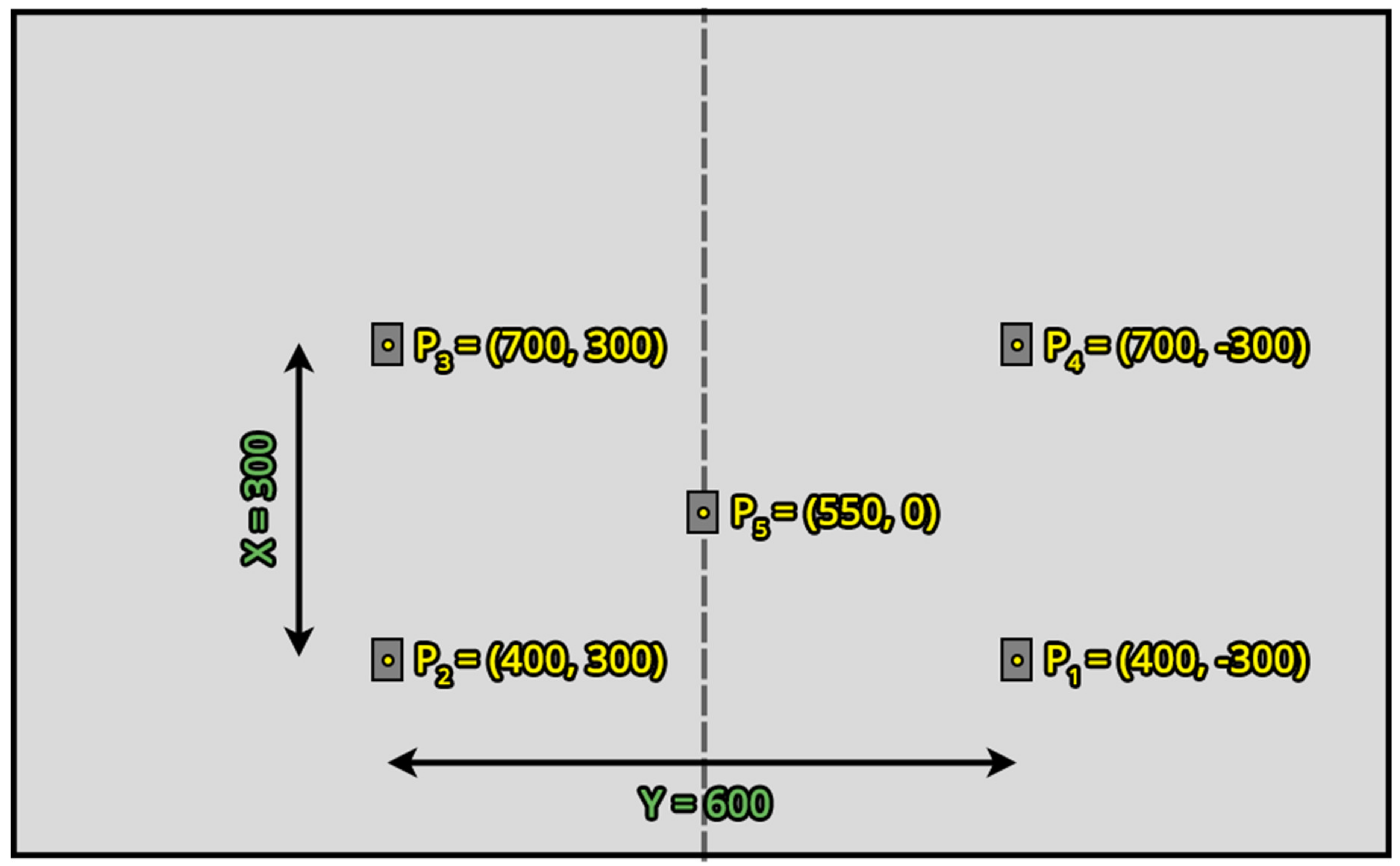
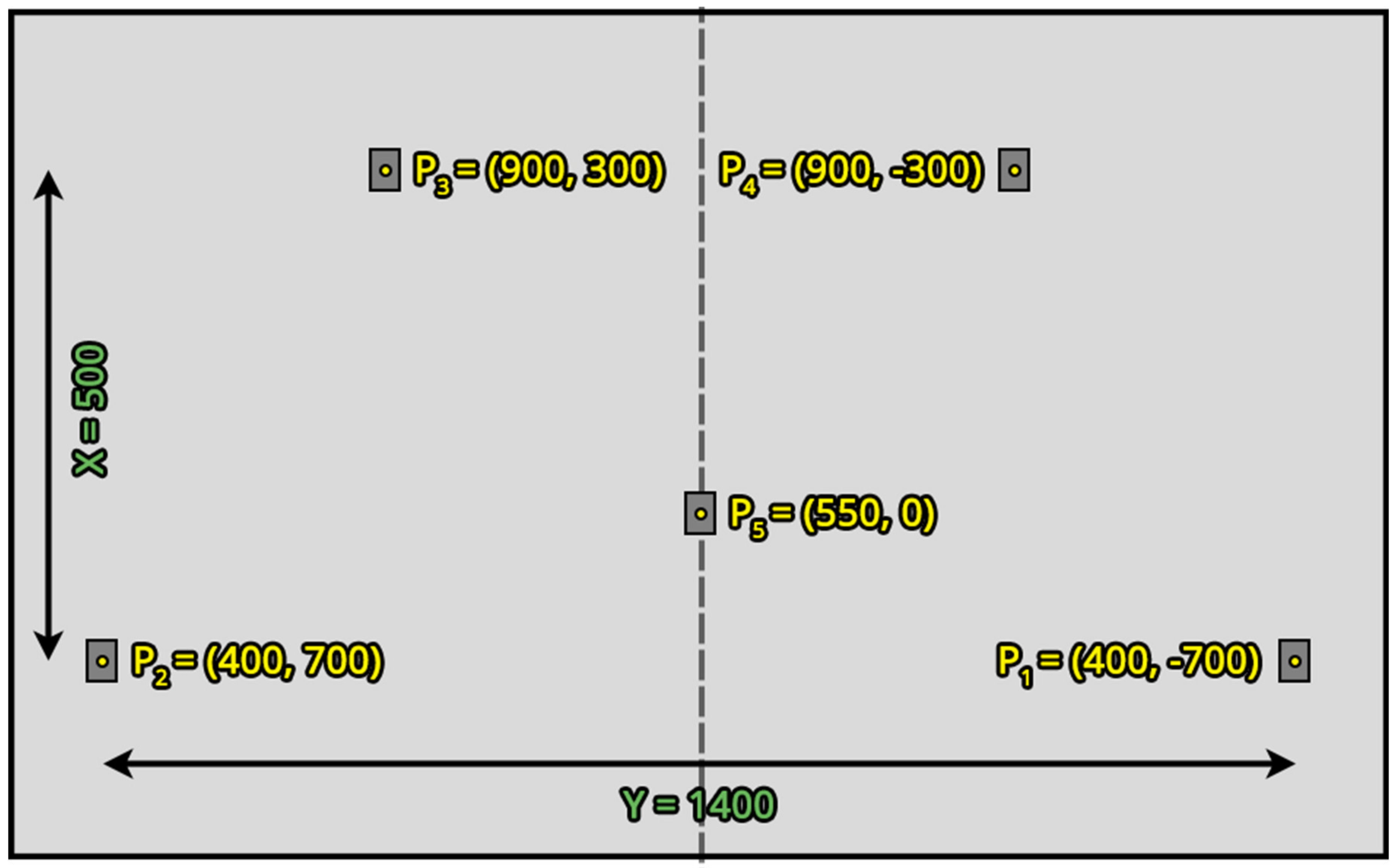
Let us consider i   =   4 points laying on a plane positioned in a rectangular shape and a fifth one positioned in the middle of it as described in the UNI EN ISO 9283 standard regulation [10]. It is possible to easily calculate matrix M given three points P i U in the user frame and their corresponding points P i ,   n R O in the robot frame chosen in order to form an edge (e.g., points P 1 , P 2 and P 4 of Figure 6). In fact, the origin point in the middle of the rectangle (e.g., P 5 of Figure 6) is easily estimated by choosing these three points and averaging their coordinates.
To compute the other values of M corresponding to the rotation parameters, it is sufficient to evaluate the two vectors connecting P 1 to P 2 and P 1 to P 3 , namely v 12 and v 13 :
v 12   =   x 2     x 1 ,   y 2     y 1 ,   z 2     z 1 v 13   =   x 3     x 1 ,   y 3     y 1 ,   z 3     z 1
From these vectors, it is possible to find the versors representing the rotations along the three axes, as follows:
k ^   =   v 12   ×   v 13 | | v 12   ×   v 13 | | 𝚤 ^   =   v 12 | | v 12 | |   𝚥 ^   =   𝚤 ^   ×   k ^ .
Therefore, the matrix M is obtained by substituting the versors values calculated in Equation (4) and the origin point coordinates in Equation (2), resulting in:
M   = i x j x k x i y j y k y i z j z k z   0 0 0   |   O x   O y   O z 1
Again, to be compliant to the standard regulation [10], the procedure just described has been repeated for n   =   30 times. In practice, after the definition of points P i U and P i R , the offsets F i , n have been added to each point, obtaining points P i ,   n R O . Therefore, a total of n affine transformation matrixes M n have been calculated.

2.2. Five-Points Calibration

The matrix M may be calculated only with three points, i.e., using only three vectors to calibrate the robot frame resulting in a simpler method that, however, may result in inaccurate positionings. To reduce these potential errors, more than three points should be adopted.
In the case of multiple couples of points P i U and P i R representing the same position in different reference systems, matrix M may be estimated by solving a linear system using the least squares method [36]. The more points are used to estimate M , the more accurate the resulting matrix is, provided that very few outliers are adopted.
Hence, given the procedure detailed in Section 2.1, in this case, to obtain the robot points P i R according to Equation (1), it is necessary to calculate the optimal matrix M that best fits the points by solving a linear system:
B n =   M n ·   A ,
which is solved by providing two matrixes, that contain the five points coordinates in the two reference frames, to the least squares method:
A =   x 1 U y 1 U z 1 U 1 x 2 U y 2 U z 2 U 1 x 3 U y 3 U z 3 U 1 x 4 U y 4 U z 4 U 1 x 5 U y 5 U z 5 U 1 ,
B n =   x 1 , n R O y 1 , n R O z 1 , n R O 1 x 2 , n R O y 2 , n R O z 2 , n R O 1 x 3 , n R O y 3 , n R O z 3 , n R O 1 x 4 , n R O y 4 , n R O z 4 , n R O 1 x 5 , n R O y 5 , n R O z 5 , n R O 1 .
In a similar way to the procedure described in Section 2.1, this has been performed n   =   30 times, hence obtaining M n calibration matrixes by using n sets of P i ,   n R O points.

2.3. Robot Positioning System Calibration

The robot built-in calibration method called Robot Positioning System (RPS) [
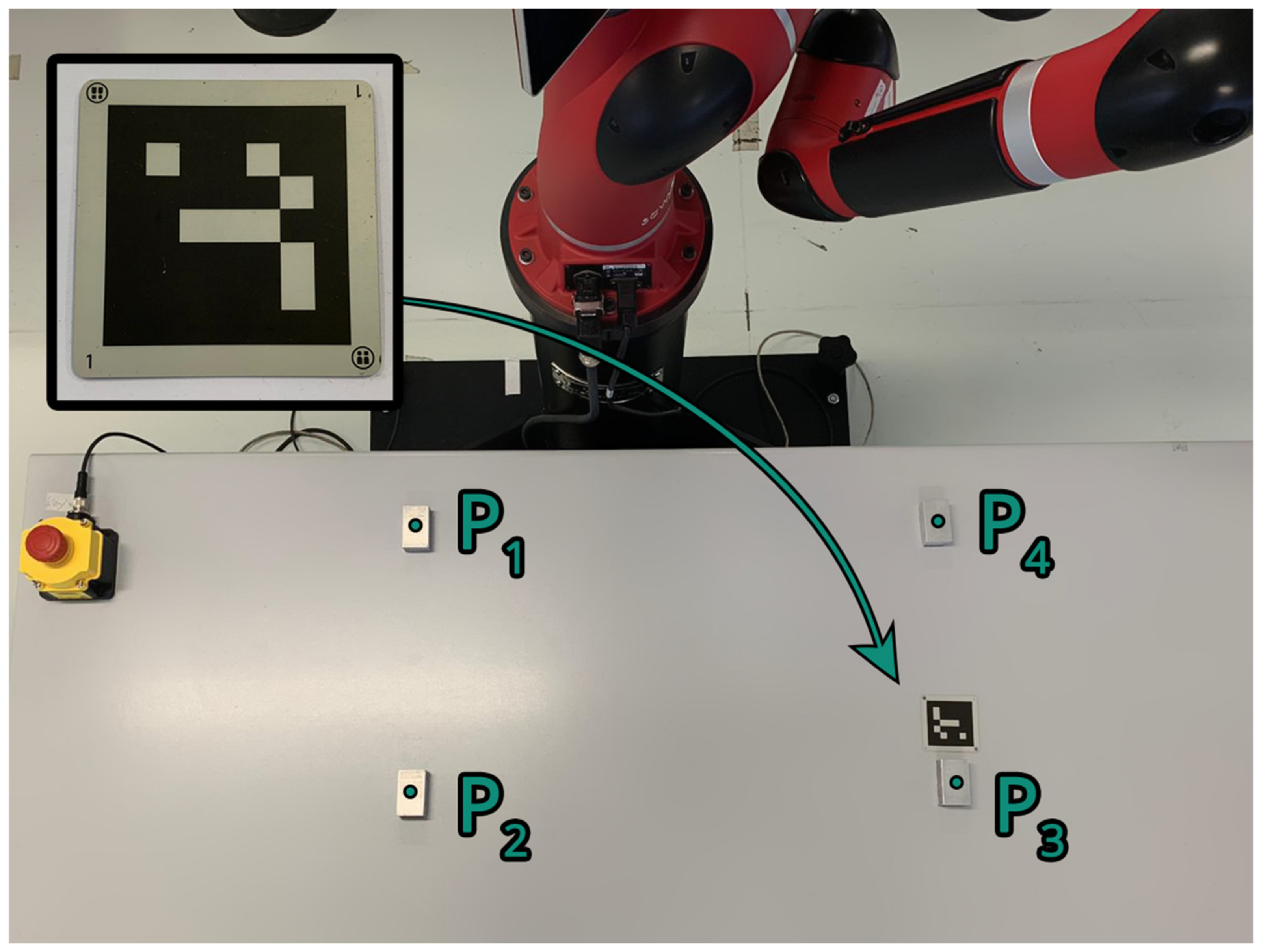
37] is a vision-based calibration method that leverages the Sawyer robot monochrome wrist camera. Thanks to this system, users may quickly calibrate a working plane by placing a fiducial marker called “landmark” on the flat surface of choice (Figure 2). The system calculates the plane position and orientation by analyzing the spatial distortions of the landmark grid in the monochrome images taken by the wrist camera, thus computing the camera projection of the landmark grid points. This procedure is similar to the standard fiducial marker calibration described in Reference [32]. As detailed in Reference [37], to perform this calibration, the user moves the robot arm in manual guidance in correspondence of the landmark placed on the surface to calibrate. Then, the vision system mounted on the robot wrist takes some pictures of the scene, finds the landmark, and the built-in software automatically computes a plane that fits the position and orientation of the object by analyzing the distortion of its black and white grid.
However, this procedure computes planes locally around the landmark. Hence, even if more landmarks are placed on the surface, they are not used to compute a single calibration plane that considers their individual contributions; instead, local planes are computed around each fiducial marker.
Therefore, in this work, this calibration procedure has been carried out by placing a landmark in between points P 3 and P 4 (Figure 2). After the plane has been created by the software, the resulting affine transformation matrix has been used to move the robot to all the points of the set-up. It is worth noting that Sawyer robots possess (i) an internal operative system called Intera and (ii) a ROS (Robot Operative System) interface, leaving to users the choice of the method to use to operate the robot. However, Intera cannot be modified by users, especially non-expert ones, to implement custom-made software or even to export internal variables, such as the affine transformation matrix that the RPS system computes. This limits the procedure, forcing users to create custom software for the ROS interface instead if they wish to implement new functionalities.

3. Positioning Repeatability Calculation

To estimate the positioning repeatability of the robot, it is necessary to calculate the distance d i of each actual position reached by the end-effector from a reference point. To simplify the set-up, this was performed by using a custom-made rectangular aluminum object (alloy 6061-O) of size 50 × 30 × 20 mm3 (aluminum marker, AM) and measuring the distance from the end-effector along the z-axis only, using a proximity sensor mounted on the end-effector. The acquisition has been repeated n   =   30 times; hence, for each point P i n distance values d i , n have been obtained. To properly compute the deviation σ i of the data, it is necessary to calculate (i) the mean of the data d 𝚤 ¯ for each point as in Equation (9), (ii) the distance from the mean D i , n corresponding to each single data d i , n shown in Equation (10), and (iii) the resulting mean D 𝚤 ¯ in Equation (11).
d 𝚤 ¯ =   1 n   k   =   1 n d i , k ,
D i , n =   d i , n     d 𝚤 ¯
D 𝚤 ¯ =   1 n   k   =   1 n D i , k .
Then, the deviation σ i of the data for each point may be computed as:
σ i =   k   =   1 n   D i , k     D 𝚤 ¯ 2 n     1 .
The positioning repeatability for each point is obtained as:
R P i =   D 𝚤 ¯   +   3 σ i .
Finally, a single parameter is defined to summarize the overall performances of the robot and to allow comparisons between tests. This value, called R P a l l , is an averaged sum over the individual R P i values obtained for each point P i calculated as following:
R P a l l =   p   =   1 i R P p i .
It is worth noting that the repeatability calculated in the following experiments may be different if the point to which the robot moves to has been calculated, thanks to the application of a calibration matrix M , or not. In the first case, the resulting repeatability refers to the calibration itself; hence, it is a measure of how well the user frame has been calibrated with respect to the robot. On the other hand, by moving the manipulator to a certain known position (by sending to its controller the corresponding waypoint in robot coordinates), the resulting repeatability refers to the robot (reference repeatability).

4. Experimental Analysis

4.1. Inductive Proximity Sensor Calibration

The sensor adopted in this work is a single-axis inductive proximity sensor Proximity Meggit TQ 402 with measurement range of 0.2–2.2 mm that has been mounted on the end-effector by using a custom 3D printed carrier. The sensor was calibrated on a specimen of the reference target.

4.2. Positioning Repeatability Performances after RPS Calibration

As detailed in Section 2.3, the RPS method has been designed to be simple and fast to use by line operators. However, it does not consider the non-planarity of the surface as much as traditional calibration procedures do. In fact, by using a single fiducial marker to calibrate the plane instead of a set of rigid markers, the resulting plane may not consider the non-planarity of the surface, which may affect the final end-effector positioning especially in correspondence of points distant from the robot base. Therefore, this experiment aims to compare the robot repeatability (i) after the user frame has been calibrated using the RPS system and (ii) without calibration, hence directly moving the robot end-effector to known points in the user frame with no recalculation in-between.
According to the UNI EN ISO 9283 standard regulation [10], the positioning repeatability of an industrial robot manipulator must be assessed following a standard procedure which involves an external sensor to obtain the actual position of the end-effector, for example a proximity sensor, such as the one described in Section 4.1.
Since the sensor can only measure one axis at a time, three set-ups have been designed to determine the overall robot repeatability testing each axis separately. Four AMs have been positioned forming a square on the planar surface according to the set-up adopted, as shown in the example of Figure 1. By moving the sensor near an AM, it is possible to read a tension variation which corresponds to a distance measure according to the sensor calibration described in Section 4.1.
The repeatability results obtained for each axis by using the RPS system have been compared with the reference repeatability obtained considering only the robot mechanical characteristics. This is easily obtained by applying Equations (9)–(14) to the distances read by the sensor obtained by moving the robot end-effector to the P i R points using an optimal z value for each of them (i.e., z 1 for P 1 R , z 2 for P 2 R , and so on). This reference repeatability shows how much the robot characteristics affect the specific positioning repeatability of the adopted set-up without considering the re-calculation of the points performed by applying Equation (1).
The experiment has been performed testing each axis one at a time; hence, the set-up has been modified accordingly to allow testing all the axes. First, the robot has been moved to each point P i corresponding to the AMs to obtain the reference repeatability values. Then, the RPS landmark has been placed on the surface to compute the new positions, in correspondence of which a reading from the proximity sensor has been obtained. For each test, the robot has been moved on points P i a total of n   =   30 times.

Results and Discussion

In Table 1, Table 2 and Table 3 the repeatability values obtained for each point P i and the corresponding R P a l l value of each test are shown for each axis independently. Figure 2, Figure 3 and Figure 4 show a comparison between the positions obtained for each point during both tests: P i R E F correspond to the reference distances used to calculate the reference repeatability, while P i R P S correspond to the ones used to calculate the RPS calibration repeatability. It is made evident that the distances registered during the RPS test are sensibly higher with respect to the reference ones for the three axes. In particular, the robot reference repeatability obtained for the y-axis is worse compared to the reference repeatability achieved for the other two axes ( R P a l l of 0.16 mm compared to 0.08 mm). However, even if the deviation of points P i R E F and P i R P S is comparable for both x and y axes (Figure 2 and Figure 3), this is not the case for the z-axis. In fact, as shown in Figure 4, the deviation of points P i R E F is very low compared to the deviation of points P i R P S .
These results show that the RPS method does not achieve high positioning performances; hence, it is not suggested as the calibration method for delicate and precise tasks. This is probably due to how the affine transformation matrix is computed by the software, which takes into account only one fiducial marker at a time to compute a local plane as discussed in Section 2.3. Therefore, the position of the landmark highly affects the repeatability of the robot that may be observed, in fact, as shown in Table 1, Table 2 and Table 3 the values obtained in correspondence of points P 3 and P 4 (closer to the landmark) are lower compared to the others. This is extremely evident in Figure 4, where it is shown that the box plots corresponding to points P 3 R P S and P 4 R P S are smaller compared to the ones obtained for P 1 R P S and P 2 R P S . Considering that the adopted set-up was not particularly wide, achieving such different repeatability values between points P 1 R P S and P 2 R P S and P 3 R P S and P 4 R P S is very worrying. This behavior highlights the need of a calibration procedure that considers more landmarks to compute a global user-frame, hence improving the overall performances of the robot.

4.3. Positioning Repeatability Performances after Three-Points and Five-Points Calibrations

As a consequence of the results described in Section 4.2, this experiment aims to determine the performances of two standard calibration methods involving rigid markers.
Following the procedure detailed in the UNI EN ISO 9283 standard regulation [10], the robot has been positioned in i   =   5 different locations of its workspace, and, for each cycle, the robot moved to the five positions P i , for a total of n   =   30 times. Five AMs of size 50 × 30 × 20 mm3 have been positioned on a table following the shape described in Reference [10] and shown in Figure 5. To perform the measurements, the same single-axis proximity sensor used for the experiment in Section 4.2 has been mounted on the robot end-effector.
As highlighted from the previous experiment, the table was not perfectly planar, a situation that often occurs in industrial scenarios. Therefore, the AMs were not laying on the exact same plane; on the contrary, they had different heights according to their position on the table. This deformation affects the measurements especially when the markers are placed to cover most of the table surface, resulting in a bigger calibration area. As a result, the measurements have been repeated twice for each analysis: one considering the markers placed in a small area at the center of the table (“close” set-up in Figure 5), and the other considering the markers placed in a bigger area that covers most of the table surface (“wide” set-up in Figure 6). The non-rectangular shape of the “wide” set-up is due to the fact that the robot could not reach some positions; hence, points P 3 and P 4 have been chosen in order to be reached, while still being sufficiently distant along the robot x coordinate.
It is worth mentioning that, if the resulting point P i ,   n R O had a z value too close to the AM (thus risking touching it with the sensor tip), a mathematical offset F F i , n has been added to avoid it. This offset has been calculated for each point and for each cycle n, resulting in different values. These have been (i) added to the original point if it was too close to the AM surface to move the robot away from it or (ii) subtracted if the original point was outside the proximity sensor measurement range, thus moving the end-effector closer to the AM surface. Therefore, in both cases, the d i , n used to calculate the repeatability values in Equation (9) have been consequently modified:
d i , n =   d i , n   +   F F i , n       i f       P i ,   n R O   =   x i , n R ,   y i , n R ,   F i , n   F F i , n ,   1 d i , n =   d i , n     F F i , n       i f       P i ,   n R O   =   x i , n R ,   y i , n R ,   F i , n +   F F i , n ,   1  

Results and Discussion

In Table 4 and Table 5, the positioning repeatability values are compared with each other and with the reference repeatability. These values have been obtained for each point P i calculated with respect to the set-up (“close” or “wide”) and with respect to the calibration used to calculate the robot points P i ,   n R O .
From these results, it is made evident that, as already stated by the literature, by using more points to compute the user frame plane, better results may be achieved. In fact, the best calibration approach is the five-points one, which greatly reduces the repeatability deviation, thanks to the estimation of the best fit matrix M n , as highlighted by the R P a l l value obtained by the five-points calibration approach that is very close to the reference one. However, it is worth noting that both methods achieve extremely low R P a l l values in both set-ups when compared with the ones observed in the case of the RPS method. Hence, considering the results and limitations of the RPS method discussed in Section 4.2, even adopting three-points instead of one could highly improve the repeatability results. Moreover, even if the five-points R P a l l values are lower compared to the ones achieved by the three-points method, this difference is not high. Furthermore, it is shown that the R P a l l values are already quite close to the reference repeatability: this highlights that increasing the number of calibration points to more than five could not lead to a noticeable increase of the robot performances, leading instead to a plateau very close to the reference repeatability value, as already proved in Reference [38].

4.4. Calibration Times Comparison

Since the industry 4.0 paradigm promotes flexibility and fast reconfiguration of production lines, it is important to adopt fast yet precise enough calibration methods to quickly set up cobot-based working stations. For the three methods considered in this work, the overall time required to perform the user frame calibration has been acquired as the average of five tests performed by different users, as shown in Figure 7. For each of them, the corresponding calibration time has been acquired also considering the set-up phase.
In the case of the RPS calibration the procedure was the following: (i) the robot was rebooted and logged into the Intera interface required to perform the built-in RPS calibration procedure; (ii) a single landmark was positioned on the surface according to the procedure described in Section 4.2; (iii) the robot arm has been moved on top of the landmark ensuring that the wrist camera was able to see the landmark correctly; (iv) the landmark detection phase was started by the software which repositioned the arm in order to adjust the view and recognize the landmark distortion; and (v) the software computed the calibration plane and created the user frame node in the robot program.
The procedure performed for the three and five-points calibrations was the following (performed by using three or five markers accordingly): (i) the robot was rebooted and logged into the ROS SDK interface required to perform our custom procedures; (ii) the rigid markers have been glued on the table and their positions have been collected according to the user frame reference system; (iii) the robot has been moved in correspondence of each point with the help of a custom-made centering tool to ensure that the end-effector was correctly touching the markers centroids and, for each marker, the corresponding robot position has been saved by our ROS software; and (iv) the resulting user frame coordinates and their corresponding robot frame coordinates have been used by our software to compute the calibration plane.
From the resulting average times shown in Figure 7, it is made evident that the difference among the calibration times is low; hence, users do not benefit that much from a faster calibration procedure, such as the RPS method, at the cost of very poor performances. Moreover, the time difference between the three and five points methods encourages users to adopt the five-points approach instead of the three-points one because the observed time variation is low. However, it is worth noting that, according to the set-up adopted and the custom software used to obtain the calibration matrix, the overall times for these two calibration procedures may be reduced. Nonetheless, given these results, it is suggested that the overall calibration times increase when more points are adopted in the procedure. Hence, users should consider this key factor in the design of their custom user frame calibration procedure.
It is worth mentioning that the number of calibration points to adopt may be limited according to the user frame and of the robot configuration. In fact, covering the user frame with calibration points may not be possible in some cases, for example, due to the presence of occlusions or due to geometry issues of both the user frame and of the cobot configuration (see, for example, the “wide” set-up in Figure 6, where some points have been positioned closer to the manipulator due to limitations in its reachable workspace). Moreover, if the user frame is of limited dimension, adopting more than three points is not beneficial for the procedure because the increase in performances is very low compared to the overall increase of the calibration time.

5. Conclusions and Future Work

This paper aimed to analyze different user frame calibration methods (vision-based and traditional mechanical methods) that may be used by practitioners working with cobots in industrial processing lines. The analysis aimed at highlighting key factors to keep in mind when designing custom user frame calibration software to achieve the best results. To our knowledge, these are details that are not sufficiently discussed in the literature, leading to incorrect and not precise calibration procedures performed by operators working on the production line. These factors are: (i) which calibration method to adopt, being it vision-based or traditional, (ii) the number of calibration points to adopt according to the set-up, and (iii) the overall calibration time.
As shown by the literature analysis, the choice of the calibration method usually depends on the working conditions of the robot and of the available equipment and software. In fact, if the cobot does not possess a built-in camera, adopting vision-based calibration methods may be difficult or not reliable enough; for example, mounting an external camera on the robot wrist could not be a feasible or steady solution that guarantees the right conditions for the method to work properly. On the other hand, traditional user frame calibration systems adopt rigid markers that may not be placed on certain set-ups and often require users to manually move the end-effector near the markers. Hence, if the cobot is supplied with a wrist camera, it is suggested to adopt fiducial markers calibration procedures because the markers are usually economic (in most cases, they can be printed by users and glued on the surfaces), and the calibration procedure is more intuitive.
Considering the Rethink Robotics Sawyer robot adopted in this work and the limitations of the built-in calibration procedure presented in Section 2.3, the quantitative analysis has been first focused on the evaluation of the robot repeatability performances achieved by adopting the RPS method. This resulted in a more complete analysis of the method’s limitations that emerged from the literature but, to our knowledge, had never been studied in detail before. Hence, we compared two traditional methods involving rigid markers to quantitatively measure the performances variations occurring when more points are adopted to obtain the user frame calibration plane.
The positioning repeatability evaluation has been performed by moving the Sawyer cobot (i) without calibration, hence obtaining a reference repeatability, (ii) after the user frame has been calibrated by a vision-based method, and (iii) after the user frame has been calibrated by two traditional mechanical methods. The vision-based method adopts the proprietary RPS system of Rethink Robotics, involving a fiducial marker and the monochrome camera mounted on the cobot wrist, needed to estimate the pose and orientation of the landmark to compute the affine transformation matrix. The two traditional methods considered in this study are standard procedures to compute the affine transformation matrix needed to calibrate the user frame by solving a three or five-points linear system, as described in the UNI EN ISO 9283 standard regulation.
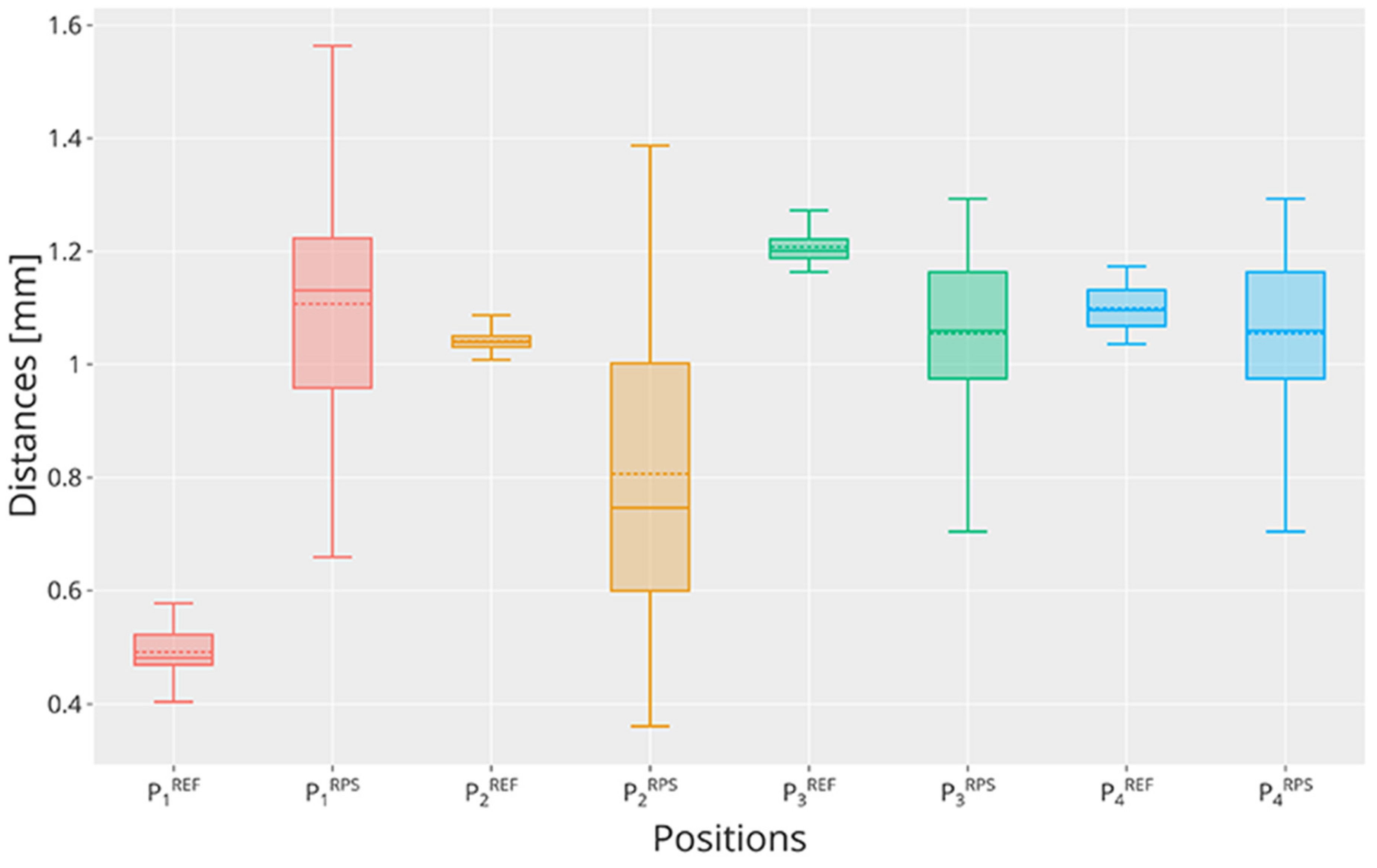
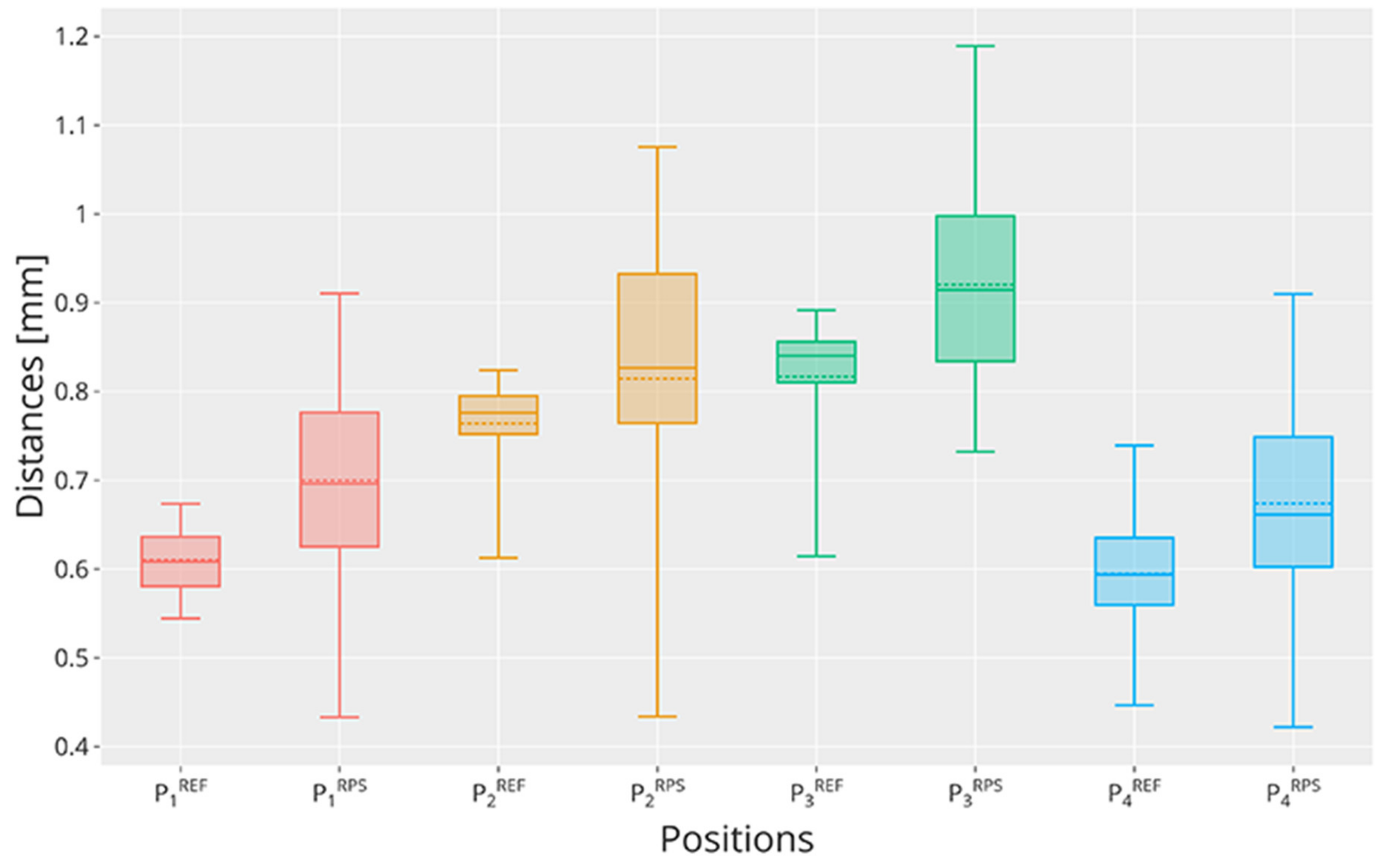
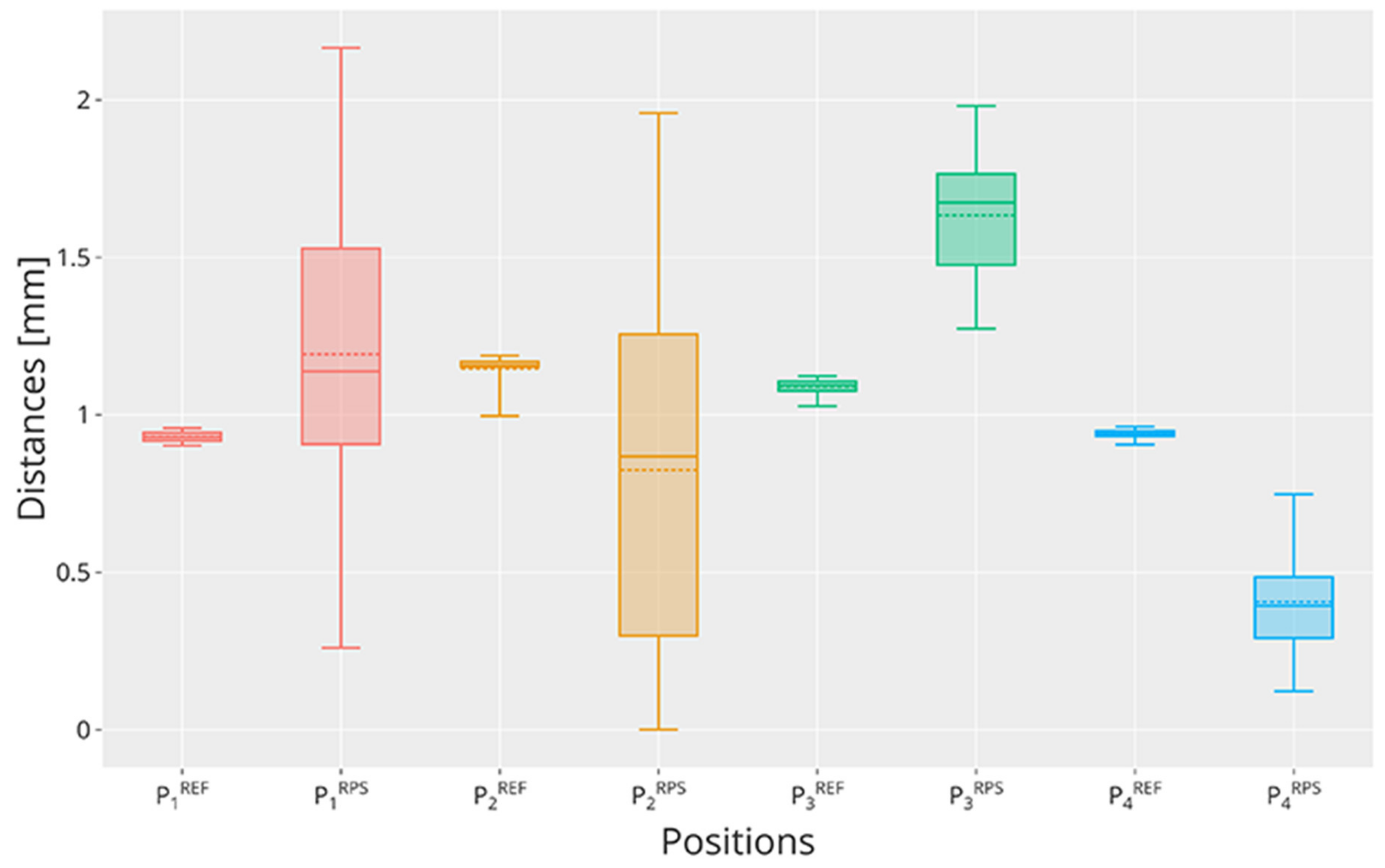
First, the analysis has been conducted on the RPS system alone, which has been tested for all axes independently. It is important to stress that, since the RPS system is a proprietary software of Rethink Robotics, it was not possible to modify the calibration procedure which only adopts one landmark at a time and computes a local plane around it. Hence, the affine transformation matrix resulting from the procedure is not accurate and does not model the entire surface in a satisfactory way. Moreover, even if the surface is covered by landmarks, the resulting planes are computed locally, hence the procedure does not consider the contribution of several landmarks in the calculation of the affine transformation matrix. This is a serious issue of this procedure that non-expert users may ignore, which is made evident by the results of this experiment. In fact, the repeatability values of the tested points are extremely different and depend on the position of the landmark used: values less than 1 may be observed for points closer to the landmark, while values close to 2 may be observed for the other two. This is particularly worrying since the surface to calibrate was of limited dimension, pointing out that the local plane computed by the RPS system is very small.
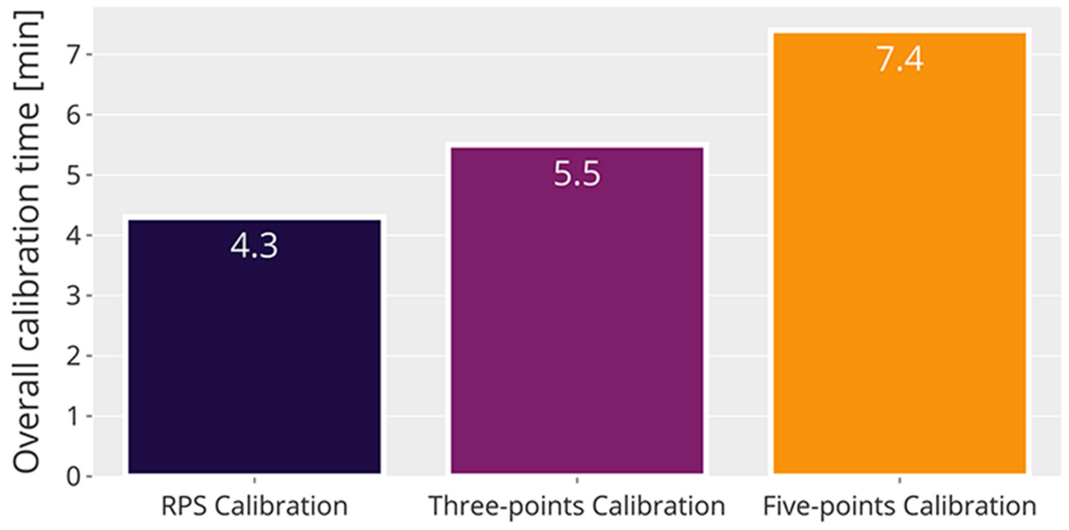
Second, the analysis focused on the comparison of two traditional calibration methods involving rigid markers and was aimed at determining the ideal number of calibration points to adopt in a user frame calibration procedure. As expected, adopting five-points leads to the best results because, by optimizing the transformation matrix using more points, the estimation of the point coordinates in the new reference system is typically better. However, it is shown that increasing the number of points also increases the overall calibration time required. Furthermore, since the repeatability values cannot be better than the reference repeatability, it is also shown that incrementing the number of calibration points to more than five does not guarantee major improvements on the performances. It is also worth noting that, in some cases, due to the user frame limitations, such as the presence of occlusions or geometry issues of both the user frame and the cobot adopted, the number of calibration points to use may be limited. Hence, by using only three points it is shown that the repeatability results are overall good in exchange of a reduced amount of time needed to perform the calibration. Nevertheless, it should be investigated if other conditions may have affected the measures, for example (i) the environmental conditions, such as temperature and vibrations, (ii) the robot stability, and (iii) the numerosity of the sample. Such considerations deserve a different and more rigorous study in the future to correctly address the contribution of each of these conditions.
Given the serious issues of the RPS calibration procedure that resulted from the experiments, in future works, we aim to develop a ROS-based calibration procedure involving more landmarks for the Sawyer cobot, hence obtaining a refined transformation matrix that could consider the eventual distortions of the plane on which the user frame lays. In fact, it is shown that, when calibrating a wider space, the results get generally worse for each calibration method; thus, a better calibration procedure should involve more points if the surface is particularly wide or irregular. However, this behavior is also influenced by the mechanical characteristics of the cobot, such as vibrations and geometrical limbs limitations. Therefore, if the cobot must operate in a wide workspace, it is suggested to plan the task accordingly to reduce these effects. Possible solutions may be to reduce the robot operating cycle or its speed, hence avoiding wide limb movements whenever possible.

Author Contributions

Conceptualization, M.L. and A.B. Methodology, C.N. and M.L. Software, M.G. and R.P. Validation, R.P., M.G. and C.N. Formal analysis, C.N. and M.L. Investigation, R.P. Resources, M.G. Data curation, C.N. Writing—original draft preparation, C.N. and R.P. Writing—review and editing, C.N. and R.P. Visualization, M.G., R.P. and C.N. Supervision, M.L., A.B. and G.L. All authors have read and agreed to the published version of the manuscript.

Funding

This research received no external funding.

Institutional Review Board Statement

Not applicable.

Informed Consent Statement

Not applicable.

Acknowledgments

The authors would like to thank Gabriele Coffetti and Marco Di Leo for the help and support given during the experiments.

Conflicts of Interest

The authors declare no conflict of interest.

References

  1. Colgate, J.E.; Peshkin, M.A.; Wannasuphoprasit, W. Nonholonomic Haptic Display. In Proceedings of the IEEE International Conference on Robotics and Automation, Minneapolis, MN, USA, 22–28 April 1996. [Google Scholar]
  2. Colgate, J.E.; Wannasuphoprasit, W.; Peshkin, M.A. Cobots: Robots for Collaboration with Human Operators. In Proceedings of the International Mechanical Engineering Congress and Exhibition, Atlanta, GA, USA, 17–22 November 1996. [Google Scholar]
  3. Sherwani, F.; Asad, M.M.; Ibrahim, B.S.K.K. Collaborative Robots and Industrial Revolution 4.0 (IR 4.0). In Proceedings of the 2020 International Conference on Emerging Trends in Smart Technologies (ICETST), Karachi, Pakistan, 26–27 March 2020. [Google Scholar]
  4. Nuzzi, C.; Pasinetti, S.; Pagani, R.; Ghidini, S.; Beschi, M.; Coffetti, G.; Sansoni, G. MEGURU: A gesture-based robot program builder for Meta-Collaborative workstations. Robot. Comput. Integr. Manuf. 2021, 68, 102085. [Google Scholar] [CrossRef]
  5. Scoccia, C.; Palmieri, G.; Palpacelli, M.C.; Callegari, M. Real-Time Strategy for Obstacle Avoidance in Redundant Manipulators. In Advances in Italian Mechanism Science; Springer International Publishing: Cham, Switzerland, 2021; pp. 278–285. [Google Scholar]
  6. Østergaard, E.H. The Role of Cobots in Industry 4.0; Universal Robots: Odense, Denmark, 2017. [Google Scholar]
  7. Matheson, E.; Minto, R.; Zampieri, E.G.G.; Faccio, M.; Rosati, G. Human–Robot Collaboration in Manufacturing Applications: A Review. Robotics 2019, 8, 100. [Google Scholar] [CrossRef] [Green Version]
  8. Guerin, K.R.; Lea, C.; Paxton, C.; Hager, G.D. A framework for end-user instruction of a robot assistant for manufacturing. In Proceedings of the 2015 IEEE International Conference on Robotics and Automation (ICRA), Seattle, WA, USA, 26–30 May 2015. [Google Scholar]
  9. Djuric, A.M.; Urbanic, R.J.; Rickli, J.L. A Framework for Collaborative Robot (CoBot) Integration in Advanced Manufacturing Systems. SAE Int. J. Mater. Manuf. 2016, 9, 457–464. [Google Scholar] [CrossRef]
  10. UNI EN ISO 9283. Manipulating Industrial Robots—Performance Criteria and Related Test Methods. Available online: https://global.ihs.com/doc_detail.cfm?document_name=ISO%209283&item_s_key=00120616 (accessed on 1 September 2020).
  11. Slamani, M.; Nubiola, A.; Bonev, I. Assessment of the positioning performance of an industrial robot. Ind. Robot 2012, 39, 57–68. [Google Scholar] [CrossRef]
  12. Wang, D.-S.; Liu, X.-G.; Xu, X.-H. Calibration of the arc-welding robot by neural network. In Proceedings of the 2005 International Conference on Machine Learning and Cybernetics, Guangzhou, China, 18–21 August 2005. [Google Scholar]
  13. Ghidini, S.; Beschi, M.; Pedrocchi, N. A Robust Linear Control Strategy to Enhance Damping of a Series Elastic Actuator on a Collaborative Robot. J. Intell. Robot. Syst. 2020, 98, 627–641. [Google Scholar] [CrossRef]
  14. Pagani, R.; Legnani, G.; Incerti, G.G.M. Evaluation and Modeling of the Friction in Robotic Joints Considering Thermal Effects. J. Mech. Robot. 2020, 12, 2. [Google Scholar] [CrossRef]
  15. Pagani, R.; Legnani, G.; Incerti, G.; Beschi, M.; Tiboni, M. The Influence of Heat Exchanges on Friction in Robotic Joints: Theoretical Modelling, Identification and Experiments. In Proceedings of the ASME 2020 International Design Engineering Technical Conferences and Computers and Information in Engineering Conference. Volume 10: 44th Mechanisms and Robotics Conference (MR), online, 17–19 August 2020; ASME: New York, NY, USA, 2020. [Google Scholar]
  16. Zhang, W.; Ma, X.; Cui, L.; Chen, Q. 3 Points Calibration Method of Part Coordinates for Arc Welding Robot. In Intelligent Robotics and Applications; Springer: Berlin/Heidelberg, Germany, 2008; pp. 216–224. [Google Scholar]
  17. Brisan, C.; Hiller, M. Aspects of Calibration and Control of PARTNER Robots. In Proceedings of the 2006 IEEE International Conference on Automation, Quality and Testing, Robotics, Cluj-Napoca, Romania, 25–28 May 2006. [Google Scholar]
  18. Roth, Z.; Mooring, B.; Ravani, B. An Overview of Robot Calibration. IEEE J. Robot. Autom. 1987, 3, 377–385. [Google Scholar] [CrossRef]
  19. Comand, N.; Bottin, M.; Rosati, G. One-Step Fast Calibration of an Industrial Workcell. In Advances in Italian Mechanism Science; IFToMM ITALY 2020; Mechanisms and Machine Science; Springer: Cham, Switzerland, 2021; Volume 91, pp. 245–251. [Google Scholar]
  20. Cheng, F.S. Calibration of Robot Reference Frames for Enhanced Robot Positioning Accuracy. In Robot Manipulators; Ceccarelli, M., Ed.; IntechOpen: Rijeka, Croatia, 2008. [Google Scholar]
  21. Gatla, C.S.; Lumia, R.; Wood, J.; Starr, G. Calibration of industrial robots by magnifying errors on a distant plane. In Proceedings of the 2007 IEEE/RSJ International Conference on Intelligent Robots and Systems, San Diego, CA, USA, 29 October–2 November 2007. [Google Scholar]
  22. Lei, S.; Jingtai, L.; Weiwei, S.; Shuihua, W.; Xingho, H. Geometry-Based Robot Calibration Method. In Proceedings of the 2004 IEEE lnternational Conference on Robotics & Automation, New Orleans, LA, USA, 26 April–1 May 2004. [Google Scholar]
  23. Duelen, G.; Schröer, K. Robot Calibration-Methods and Results. Robot. Comput. Integr. Manuf. 1991, 8, 223–231. [Google Scholar] [CrossRef]
  24. De Araujo, P.R.M.; Lins, R.G. Computer vision system for workpiece referencing in three-axis machining centers. Int. J. Adv. Manuf. Technol. 2020, 106, 2007–2020. [Google Scholar] [CrossRef]
  25. Boby, R.A.; Saha, S.K. Single image based camera calibration and pose estimation of the end-effector of a robot. In Proceedings of the 2016 IEEE International Conference on Robotics and Automation (ICRA), Stockholm, Sweden, 16–21 May 2016. [Google Scholar]
  26. Zhang, Z. A Flexible New Technique for Camera Calibration; Microsoft Research: Redmond, WA, USA, 1998. [Google Scholar]
  27. Meng, Y.; Zhuang, H. Autonomous robot calibration using vision technology. Robot. Comput. Integr. Manuf. 2007, 23, 436–446. [Google Scholar] [CrossRef]
  28. Du, G.; Zhang, P. Online robot calibration based on vision measurement. Robot. Comput. Integr. Manuf. 2013, 29, 484–492. [Google Scholar] [CrossRef]
  29. Wang, Z.; Liu, Z.; Ma, Q.; Cheng, A.; Liu, Y.; Kim, S.; Deguet, A.; Reiter, A.; Kazanzides, P.; Taylor, R.H. Vision-Based Calibration of Dual RCM-Based Robot Arms in Human-Robot Collaborative Minimally Invasive Surgery. IEEE Robot. Autom. Lett. 2017, 3, 672–679. [Google Scholar] [CrossRef]
  30. Nuzzi, C.; Ghidini, S.; Pagani, R.; Pasinetti, S.; Coffetti, G.; Sansoni, G. Hands-Free: A robot augmented reality teleoperation system. In Proceedings of the 2020 17th International Conference on Ubiquitous Robots (UR), Kyoto, Japan, 22–26 June 2020. [Google Scholar]
  31. Craig, A.B. Augmented Reality Concepts. In Understanding Augmented Reality, Concepts and Applications; Morgan Kaufmann: Boston, MA, USA, 2013; pp. 39–67. [Google Scholar]
  32. Garrido-Jurado, S.; Muñoz-Salinas, R.; Madrid-Cuevas, F.J.; Marín-Jiménez, M.J. Automatic generation and detection of highly reliable fiducial markers under occlusion. Pattern Recognit. 2014, 47, 2280–2292. [Google Scholar] [CrossRef]
  33. Pini, F.; Leali, F.; Ansaloni, M. Offline workpiece calibration method for robotic reconfigurable machining platform. In Proceedings of the 2014 IEEE Emerging Technology and Factory Automation (ETFA), Barcelona, Spain, 16–19 September 2014. [Google Scholar]
  34. Li, X.; Zhang, B. Toward general industrial robot cell calibration. In Proceedings of the 2011 IEEE 5th International Conference on Robotics, Automation and Mechatronics (RAM), Qingdao, China, 17–19 September 2011. [Google Scholar]
  35. Legnani, G.; Casolo, F.; Righettini, P.; Zappa, B. A homogeneous matrix approach to 3D kinematics and dynamics—I. Theory. Mech. Mach. Theory 1996, 31, 573–587. [Google Scholar] [CrossRef]
  36. Miller, S.J. The Method of Least Squares; Mathematics Department Brown University: Providence, RI, USA, 2006; Volume 8, pp. 1–7. [Google Scholar]
  37. Rethink Robotics. Robot Positioning System. Available online: https://mfg.rethinkrobotics.com/intera/Robot_Positioning_System (accessed on 1 September 2020).
  38. Fitzpatrick, J.M.; West, J.B.; Maurer, C.B. Predicting error in rigid-body point-based registration. IEEE Trans. Med. Imaging 1998, 17, 694–702. [Google Scholar] [CrossRef] [PubMed]
Figure 1. Example of the set-up of the Robot Positioning System (RPS) landmark-based calibration adopted to test the repeatability along the z-axis. The proximity sensor is mounted on the end-effector and the landmark is placed in between points P 3 and P 4 .
Robotics 10 00045 g001
Figure 2. Distances obtained from the proximity sensor for each position P i along the x-axis compared between the reference test and the RPS test. For each boxplot, n = 30 samples have been considered. The solid line represents the median, while the dashed line represents the mean value of each boxplot.
Robotics 10 00045 g002
Figure 3. Distances obtained from the proximity sensor for each position P i along the y-axis compared between the reference test and the RPS test. For each boxplot, n = 30 samples have been considered. The solid line represents the median, while the dashed line represents the mean value of each boxplot.
Robotics 10 00045 g003
Figure 4. Distances obtained from the proximity sensor for each position P i along the z-axis compared between the reference test and the RPS test. For each boxplot, n = 30 samples have been considered. The solid line represents the median, while the dashed line represents the mean value of each boxplot.
Robotics 10 00045 g004
Figure 5. Image showing the “close” set-up. The aluminum markers (AMs) have been glued on the table at fixed positions with corresponding robot coordinates written in yellow.
Robotics 10 00045 g005
Figure 6. Image showing the “wide” set-up. The AMs have been glued on the table at fixed positions with corresponding robot coordinates written in yellow.
Robotics 10 00045 g006
Figure 7. Average calibration times achieved for each calibration method. The averages have been obtained as the mean value of five tests performed by different users.
Robotics 10 00045 g007
Table 1. Positioning repeatability RP values obtained for the x-axis (mm).
Experiment R P 1   R P 2   R P 3   R P 4   R P a l l
Landmark RPS calibration0.770.960.470.460.70
Reference repeatability0.100.050.070.090.08
Table 2. Positioning repeatability RP values obtained for the y-axis (mm).
Experiment R P 1   R P 2   R P 3   R P 4   R P a l l
Landmark RPS calibration0.360.520.300.350.39
Reference repeatability0.080.150.200.190.16
Table 3. Positioning repeatability RP values obtained for the z-axis (mm).
Experiment R P 1   R P 2   R P 3   R P 4   R P a l l
Landmark RPS calibration1.941.910.640.471.42
Reference repeatability0.040.140.060.040.08
Table 4. Positioning repeatability RP values obtained adopting the “close” set-up (mm).
Experiment R P 1   R P 2   R P 3   R P 4   R P 5   R P a l l
Three-points calibration0.110.240.410.500.220.33
Five-points calibration0.080.130.190.100.080.12
Reference repeatability0.040.070.120.110.050.08
Table 5. Positioning repeatability RP values obtained adopting the “wide” set-up (mm).
Experiment R P 1 R P 2 R P 3 R P 4 R P 5 R P a l l
Three-points calibration0.520.380.490.690.540.53
Five-points calibration0.310.360.460.390.190.36
Reference repeatability0.230.170.200.410.040.24
Publisher’s Note: MDPI stays neutral with regard to jurisdictional claims in published maps and institutional affiliations.

