1. Introduction
Cable-driven parallel robots can be easily described as parallel robots whose rigid links are replaced by flexible cables. As parallel robots, they present several advantages with respect to serial ones because of their particular structure: thanks to their low inertial properties, the end-effector can reach high speed, ad they can manipulate high-payloads since the payload is distributed among the links [
1].
One of the shortcomings faced when adopting a parallel robot is usually the limited workspace, due to the possible collisions between links and to the presence of passive joints which have mechanical limits [
2]. Cable-driven parallel robots, hereafter called cable robots, provide a solution to this problem by replacing the links with cables wound around winches, leading immediately to a larger workspace thanks to the cable length. Moreover, they are relatively cheap, and their simple design allows for modular transportable and reconfigurable solutions [
3]. Therefore, it is easy to understand the importance of cable robots, which are adopted not only for industrial applications [
4] and entertainment [
5], but even for home assistance and rehabilitation purposes [
6], since they are non-invasive in comparison to other robots.
However, in contrast to rigid-link parallel robots, it is fundamental that the cable tension remains positive and bounded during the motion to avoid cable slackness or failure since cables can only exert tension. One possible solution is to use an external force acting on the robot moving platform to satisfy this condition. This is possible by adopting a redundant—also called overconstrained—structure [
7]; i.e., a robot composed of
m cables, with
m greater than the
n degrees of freedom. Otherwise, suspended parallel robots, which are considered in this work, take advantage of gravity to pull the cable. Despite their design being simpler than overconstrained robots (since they require fewer cables and actuators), they are more difficult to control.
Furthermore, the unilateral properties of the wires also lead to safety concerns. Thus, the design of an emergency stop procedure is more difficult than in rigid-link manipulators. Indeed, whereas for conventional robots it is usually possible to halt the end-effector and the robot structure by braking the actuators, this does not apply to cable robots: indeed, braking the actuators is usually not sufficient to stop the end-effector. Conversely, a sudden motor brake could generate uncontrollable motions [
8]. An initial analysis of cable robot failures is presented in [
9], and intuitively, the most expected failure for these robots is cable breakage. Despite following norms and guidelines that allow the reliable operation of cable robots to be ensured, faulty mechanical components or control algorithms could lead to slack or breaking cables [
10]. In [
11], the authors suggested doubling each cable with a passive auxiliary cable as a safety solution. Since this solution adds complexity to the system, a further proposal was to use a single auxiliary cable that raises the end-effector in case of failure by releasing a counterweight. The authors noted that the influence of the counterweight mass is not negligible, adding that it may difficult to determine a proper value. Indeed, a light counterweight may not raise the end-effector, whereas a heavier one may lead to an excessive overshoot of the
position.
Another solution could be to use healthy cables to recover a lost wrench, as seen in [
12]. Indeed, when a cable fails, the wrench applied by the end-effector is different from the expected one. Thus, Notash proposed two methods for recovering a lost wrench by imposing an additive tension on the remaining cables. However, this work considers that the robot remains overconstrained after failure, and thus it does not take into account any changes in the static equilibrium workspace (SEW), nor that the end-effector could lay outside it.
Indeed, the SEW—i.e., the set of end-effector poses for which static equilibrium can be achieved with positive tension in all cables [
13]—changes for underconstrained parallel robots when a cable failure occurs. Thus, it is necessary to bring the robot inside the new SEW to reach a static equilibrium. Moreover, even if it is not possible to stop the robot outside the SEW, the end-effector could be controlled outside it with positive cable tensions, as seen in [
14], where the authors performed a dynamic motion reaching outside the SEW. In their work, the end-effector reached the target point at zero speed while maintaining a positive cable tension, despite presenting a non-null acceleration of the end-effector. A similar result was presented in [
15], where the authors presented a geometric approach to define the workspace characterized by positive cable tensions. This approach was then used to design feasible trajectories, and the work shows examples of point-to-point and periodic trajectories. These works show that it is possible to move and control the end-effector outside the SEW. Moreover, they show that a major focus in recovery strategy for cable robots should be the definition of trajectories that drive and stop the end-effector inside the after-failure SEW.
Passarini et al. [
16] presented a recovery strategy based on a single elliptical trajectory that was used to steer the end-effector to a safe point inside the new SEW. Moreover, this method could be designed to avoid collisions; this is possible by keeping the platform inside a cuboid and above a predetermined height. Since the landing point was identified by minimizing the recovery time, the authors provided two approximation strategies as a replacement of the multivariable constrained optimization for real-time applications. A different approach was presented in [
17], where a recovery strategy aiming to drive the end-effector to a rest position inside the new SEW was divided into three phases. The trajectory was composed of an elliptical path, used to drive the platform inside the after-failure SEW, followed by two seventh-degree polynomial trajectories to stop the robot. This approach exploits elliptical trajectories to maintain positive cable tensions outside the SEW; moreover, it avoids the oscillatory motion through the polynomial trajectories, ensuring continuity in terms of position, velocity, acceleration and jerking. Boschetti et al. [
18] proposed a recovery strategy based on two different phases: a connecting path to change the direction of motion and a linear trajectory designed to drive and stop the end-effector at the chosen rest positions. Moreover, the authors exploited the Wrench Exertion Capability (WEC) performance index [
19] to evaluate the maximum braking forces which could be applied to the end-effector. In contrast to the previous approach, the adoption of a linear trajectory avoids large motions, reducing the risk of collisions during the recovery strategy. However, this approach requires solving linear programming problems to evaluate the force limits on the end-effector, which are time-consuming or must be precomputed.
Despite the literature presenting approximate methods for industrial applications, the feasibility of the proposed recovery strategies must be assessed in real time. For this reason, Boumann et al. [
20] investigated the computation time and real-time suitability of the method presented in [
21]. The authors adopted an alternative method based on geometrical analysis within the cable force space since the previous instance of the method was based on the resolution of an optimization problem. Tests on the algorithm computational efficiency showed that it needed about 10% of the cycle time for a 2 kHz control frequency.
From our review, the literature can be seen to propose several methods to solve cable failure in cable robot applications; however, very few of the approaches present an experimental validation besides simulations. Despite the literature often accompanying each recovery strategy with an equivalent fast approach, these have not been tested in a real prototype, and thus their suitability for real-world application is not ensured.
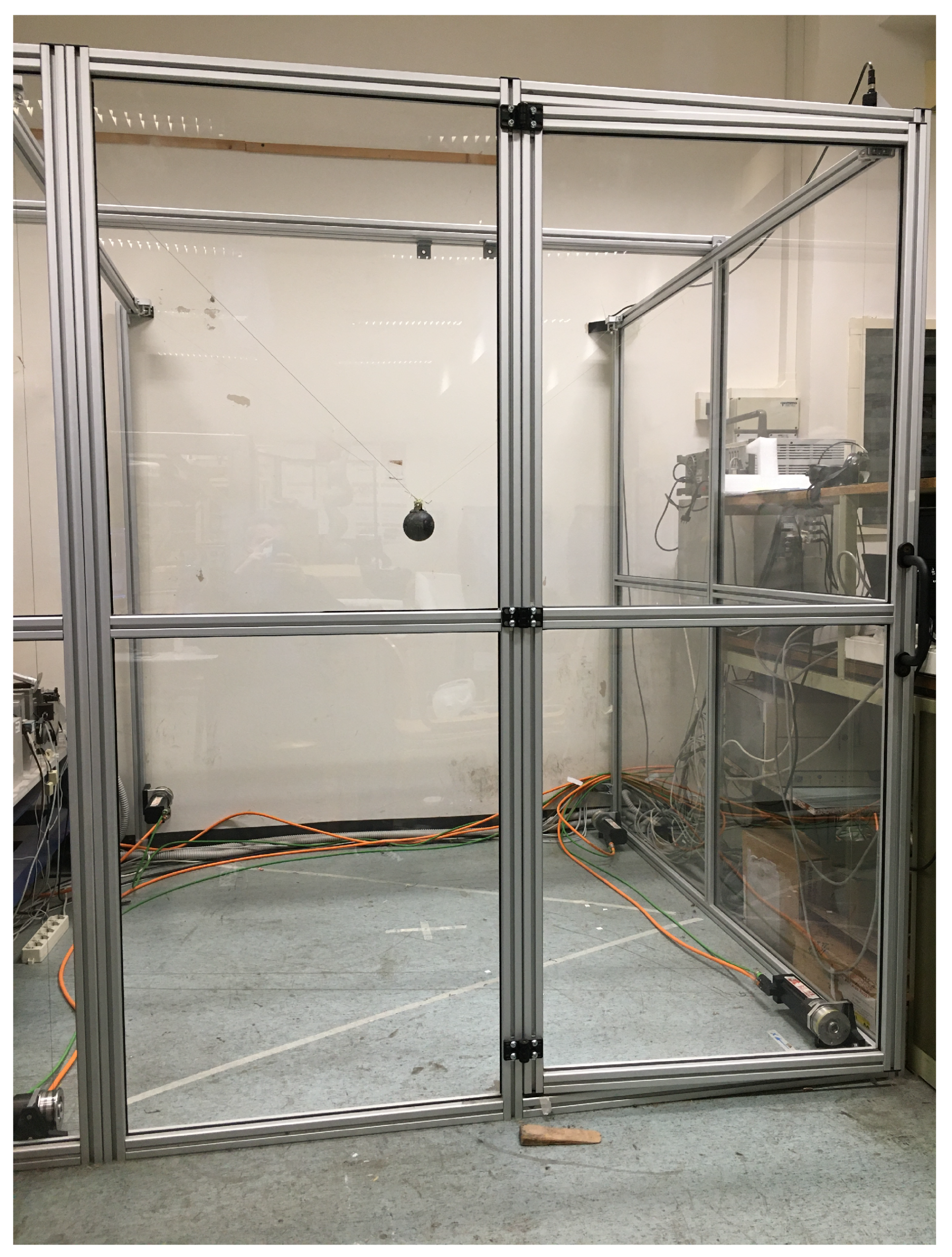
The proposed work aims to introduce a recovery strategy that is suitable for industrial applications without adopting time-consuming algorithms. This recovery strategy starts from a previously defined approach that features linear programming optimization; thus, it may not be suitable for real-time industrial applications. Indeed, an effective recovery strategy should avoid collision and provide for a fast recovery of the end-effector even when its computational efficiency is critical and in the presence of only integrated sensors, such as encoders or resolvers. Therefore, this work tests the feasibility of the proposed recovery strategy on a prototype of a three degrees-of-freedom (3-DOF) cable-suspended parallel robot; moreover, this experimental setup is composed of industrial-grade components, further highlighting the practical implication of the strategy.
This work is structured as follows:
Section 2 presents the proposed control model and recovery strategy;
Section 3 presents the experimental setup used for the tests;
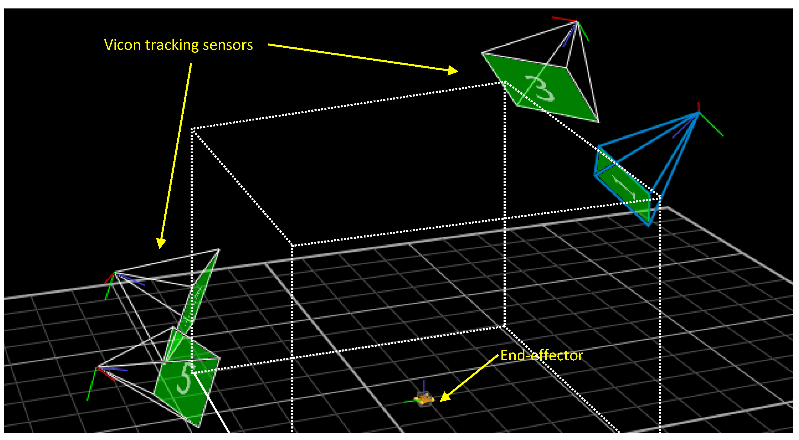
Section 4 presents the results, comparing the nominal trajectory with measurements obtained by means of a motion tracking system; and lastly,
Section 5 concludes the work.
2. Control Model
This work considers a suspended cable-driven parallel robot (CDPR) with
m cables, with each controlled by an actuator. The end-effector is connected to the frame by means of the
m cables through the exit points
to the attach points
. We consider two reference frames: the absolute frame (
O) and the local frame (
P), which is placed in the center of mass of the platform, as seen in
Figure 1. The length of the cables is represented by the vector
l
where
is the length of the
i-th cable. A generic platform presents six degrees-of-freedom (6-DOF):
where
d represents the position
p and orientation
of the platform. In this work, the end-effector was considered as a point mass since a recovery strategy generally focuses on the end-effector position. Thus, only the vector
p, and thus the first three DOFs, have been considered. Moreover, this work studies redundant cable robots characterized by
. Since this work takes into account a point mass end-effector,
n is equal to 3. Lastly, the proposed recovery strategy applies only if the after-failure architecture is at least fully actuated and the after-failure feasible workspace is not null. This last condition can be guaranteed by at least three cables whose exit points do not lay on the same vertical plane. Therefore, this work applies to over-actuated spatial cable robots; i.e., robots with at least four cables.
2.1. Motion Control
2.1.1. Position Control
A successful recovery strategy requires that the end-effector follows the evaluated trajectory; thus, a position control algorithm should be introduced. In this paper, a PID controller on the position has been used. This work adopted a PID controller due to its simple structure, avoiding the use of more complex and time-consuming algorithms. Moreover, the results were deemed suitable, as presented in
Section 4; thus, other strategies were not investigated. However, other controllers may be adopted.
Once the desired trajectory has been defined, each pose is sent to the position control algorithm. To obtain the cable length, the following inverse kinematic approach was adopted, based on the closure equation of the vectors in
Figure 1. At first, we define the vector
as the positions of the distal attachment points on the platform in the local reference frame; i.e.,
The rotation matrix
represents the orientation of the local reference frame in the global frame; thus, it is possible to evaluate the cable length
from the geometry as
Since this work models the end-effector as a point mass, is null, simplifying the equation.
From
it is possible to evaluate the actuator angular position
as
where
is the distance between the actuator and the corresponding exit point
, which is set as constant, and
is the drum radius.
The position loop compares the position feedback with the actuator sensors to evaluate the error value between the actual position of the actuators and the reference position. The adoption of the inverse kinematic model allowed us to easily compare the actuator feedback, which is defined in the joint space, with the desired position of the end-effector, which is defined in the Cartesian space.
2.1.2. Feed-Forward Control
When studying cable robots, it is necessary to ensure a positive cable tension to control the end-effector. Thus, it is necessary to take into account the system dynamics, which are not completely described by the independent joint control based on position [
22]. However, a control system based only on a feed-forward position control model that takes into account the cable tensions is not an optimal solution. Indeed, a similar approach was not deemed suitable, as it could not maintain positive cable tensions under disturbance, such as the end-effector oscillatory motion. Thus, in this work, we combined a PID position control algorithm, whose output was the corrective motor torque
, with an inverse dynamic feed-forward approach that evaluated the motor torque
, achieving the overall motor torque
, as shown in
Figure 2.
The tension of each cable can be evaluated by considering the wrench
; i.e., the forces applied to the end-effector by the cables (
) and by other external forces (
). In other words, the overall wrench can be defined as follows:
The relation between the cable wrench
and the cable tension
is given by the structure matrix
S, which is defined as follows:
where
are the unit vectors oriented from the end-effector towards the corresponding exit point
. The structure matrix allows the following equation to be defined:
An interesting approach to take into account the overall wrench (i.e., cable wrench and external wrench) with respect to cable tension
is given by the wrench matrix
W. This matrix is composed of matrix
with the vector
added as the column m+1:
In this way, the overall wrench exerted on the end-effector can be defined as follows:
However, in this application, the external wrench considers only the force of gravity. Thus, the first part of Equation (
10) can be rewritten as follows:
Since the before-failure cable robot architecture is overconstrained—i.e., redundant—
S is an
rectangular matrix, and it is therefore not possible to evaluate its inversion; however, it is possible to evaluate
by adopting the Moore–Penrose generalized inverse
:
Conversely, in the case of a fully actuated cable robot (i.e., ), S is a square matrix, and therefore its inverse matrix can be computed.
Once the proper cable tensions have been computed, the required torques
that have to be exerted by the motors can be defined as follows:
where
is the motor inertia matrix,
is the motor acceleration given by the inverse kinematics and
contains the pulley radii in its diagonal. Nonlinear terms have been neglected.
2.2. Recovery Strategy
Among the recovery strategies proposed by the literature, this work will focus on the one presented in [
23]. The goal of this strategy consists of driving the end-effector towards a safe point inside the residual SEW. Indeed, as the cable breaks, the end-effector could lay outside the static workspace, and so a pose, called SP, must be accordingly defined inside the residual SEW. Previous works have suggested several factors that influence the SP position, such as the robot pose at failure or the presence of obstacles in the workspace. In this work, the main focus was to keep the end-effector above a suitable height, defined to avoid a collision, whereas the
coordinates of the SP were defined as the barycenter of the area obtained by the intersection of the residual SEW with the horizontal plane defined at the chosen height.
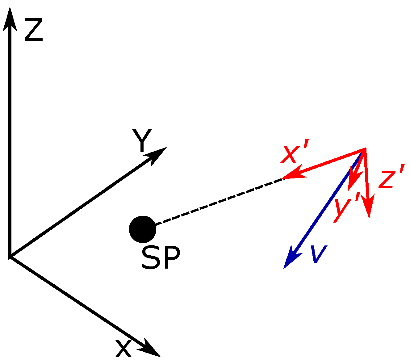
Once the SP is defined, the strategy aims to drive the end-effector towards this point. However, to generate a feasible linear trajectory, the end-effector velocity should be null or already oriented towards the SP. Therefore, before starting the linear path, it is necessary to change the direction of motion with an initial phase called a connecting path.
A mobile reference frame placed at the center of mass of the end-effector is then defined. This frame is used to readily identify the velocity components that must be reduced to a suitably small value. The mobile
axis is aligned with the vector joining the end-effector with the SP, hereafter called
. The
axis is instead aligned with the undesired velocity component. The velocity of the end-effector expressed on the mobile reference frame
is therefore
where the third component is always null due to the axis definition and
is always positive, whereas
depends on the initial motion, as seen in
Figure 3.
The corresponding braking force used to minimize the
component while keeping the
component null is defined as
From Equation (
11), it is possible to define the cable tensions
required to achieve this cable force as
where
is the rotation matrix between the mobile reference frame and the global frame,
represents the total force applied along the
axis, and therefore
, whereas
and
represent the total force applied along the other two axes:
and
, respectively.
The maximum tension
required to change the velocity direction can then be evaluated. This can be evaluated by solving a linear optimization problem or by iterative algorithms based on a fast formulation of the wrench [
24], which may suitable when the computational efficiency of the recovery algorithm is not a critical issue.
However, despite previous approaches having been proven to be effective, this work aims to provide a recovery strategy that drives the end-effector to the SP and that is feasible for different industrial real-time applications. Thus, these algorithms cannot be expensive in terms of computational time. On the other hand, a simplified recovery strategy composed of only a linear path towards the SP may present discontinuities in the cable tensions, which could lead to further cable failures if the end-effector speed is high enough. Therefore, it is necessary to reduce the end-effector speed before starting the linear path planning.
A motion planning that is able to ensure that the z position of the end-effector remains above a certain minimum value is needed; thus, it is necessary that at least some cables sustain the platform weight. In this work, the cables adjacent to the broken one were chosen to maintain the end-effector at a proper height.
Therefore, the complete approach is divided into two phases:
As the cable i fails, the cables and react by sustaining the platform weight; at the same time, the other remaining cables move the platform towards the SEW by keeping a constant tension and thus lowering their length . This allows for a feasible trajectory, since it is performed with constant ;
When the end-effector speed is low enough, a linear trajectory towards the SP is planned, as mentioned above, thus stopping the end-effector where desired.
Despite the end-effector position and velocity not being known beforehand, it is however possible to define the acceleration limits and therefore plan a linear trajectory towards the SP. This is possible by exploiting the Wrench Exertion Capability (WEC) index [
25] andevaluating the maximum and minimum breaking force achievable along the direction of
; thus, the acceleration is limited during the linear trajectory.
By referring to the previously defined mobile reference frame—i.e., with the
axis aligned with
,
the WEC formulation in [
19] requires a linear programming problem to be solved to evaluate the maximum exertable force
along
:
Due to the local nature of the WEC index, the approach requires the linear programming problem to be solved for a certain number of points, decided by compromising between the desired accuracy and the computational efficiency of the algorithm. Similar to the previous phase, it is possible to adopt the fast WEC formulation to evaluate the maximum breaking force
and therefore the acceleration limits
as
It should be noted that this formulation does not consider the actuator torques; thus, it is necessary to add an additional step to verify that the torques corresponding to the evaluated acceleration limits satisfy the torque constraints.
Once
has been defined, it is possible to plan the trajectory along
. This work adopts a fifth-degree polynomial motion law since it is easy to implement and evaluate even in the case of real-time applications. On the other hand, it is only possible to constrain the acceleration on the end-points; therefore, it is necessary to later verify that the evaluated motion law respects the acceleration constraints [
24].
The adopted motion law is defined on the basis of the following constraints:
where
T is the total motion time and
and
are the position and the velocity, respectively, after the precedent phase. The value of the starting acceleration
is set equal to the maximum possible acceleration at half of the distance, approximating the polynomial motion law to a triangular motion profile in the first design phase.
Since the computed acceleration, and therefore the motion law, is evaluated in the mobile reference frame, it is necessary to express it in the spatial reference frame, allowing the evaluation of the inverse kinematics and therefore the required motor torques:
where
is the acceleration on the absolute reference system and
is the acceleration in the mobile reference frame.
4. Experimental Results
The following section describes the performed experiments: at first, tests on a circular reference trajectory were carried out to verify the reliability of the motion tracking system, and then tests were performed with the proposed recovery strategy.
4.1. Circular Trajectory
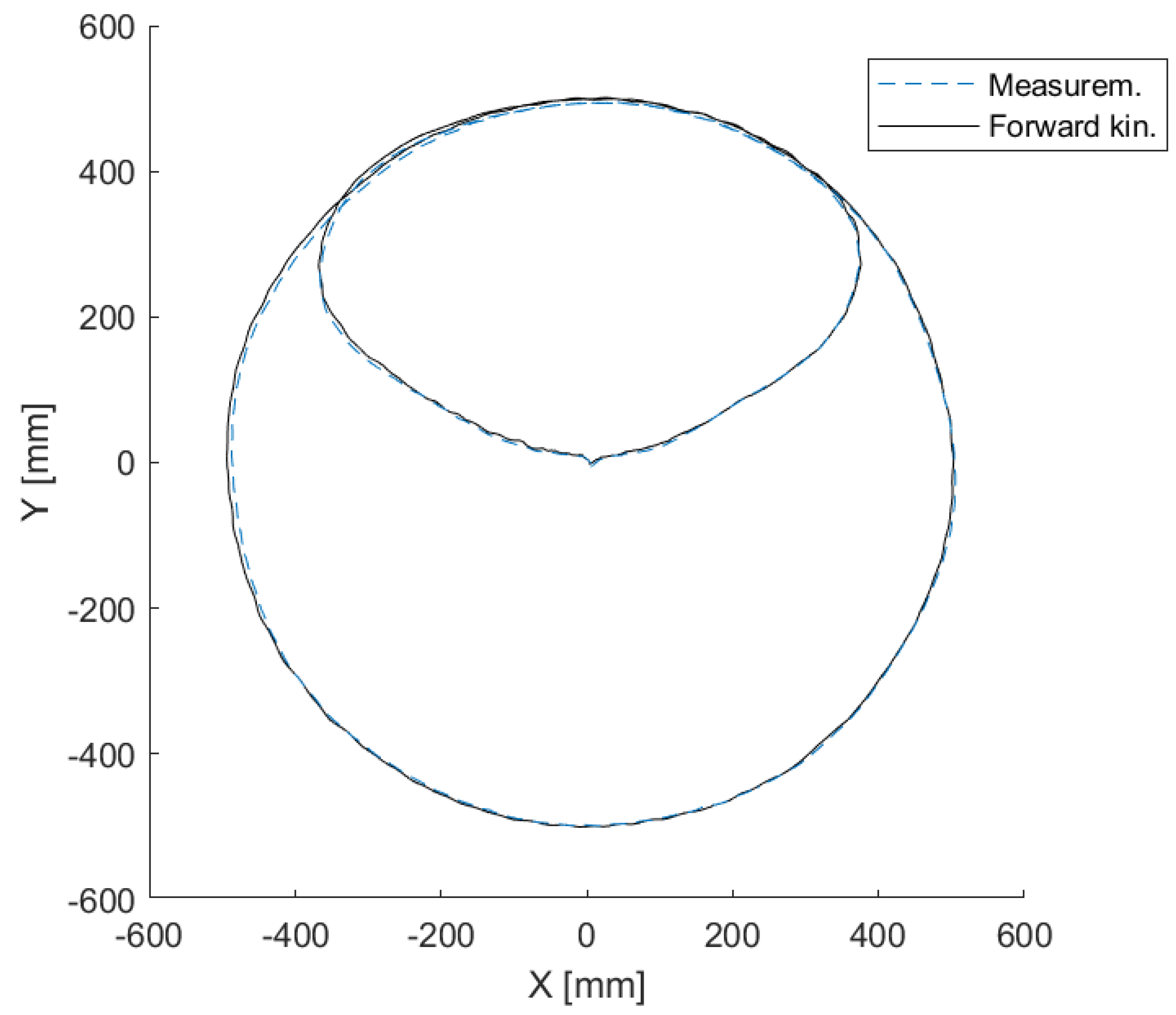
A circular trajectory was planned for the tests. Its radius was 500 mm and its center was positioned in the center of the workspace; i.e., at coordinates m. The absolute reference frame was positioned in the center of the workspace floor. The center of the circle was set as the starting and final point of the trajectory. For this reason, two connecting paths were defined, preceding and following the circular trajectory, respectively. Lastly, the motion time was set to be equal to 11 s.
The Cartesian trajectory, obtained from the resolvers’ data, is compared with the Vicon data in
Figure 7, where the continuous line represents the trajectory obtained from the direct kinematics algorithm (resolvers’ data), and the dashed line represents the data measured by the motion tracking system.
These results show a close matching between the two trajectories.
Figure 8 shows the measured torque of each actuator during this motion. It is possible to notice that the motors continuously pulled the cables to keep them taut. A very small unwinding torque was measured on each actuator when the end-effector was far from the corresponding cable exit point (e.g. motor 3 presented a torque of 0.04 Nm at 5.5 s). Such a torque was imparted by the feed-forward to promptly compensate for the motor inertia.
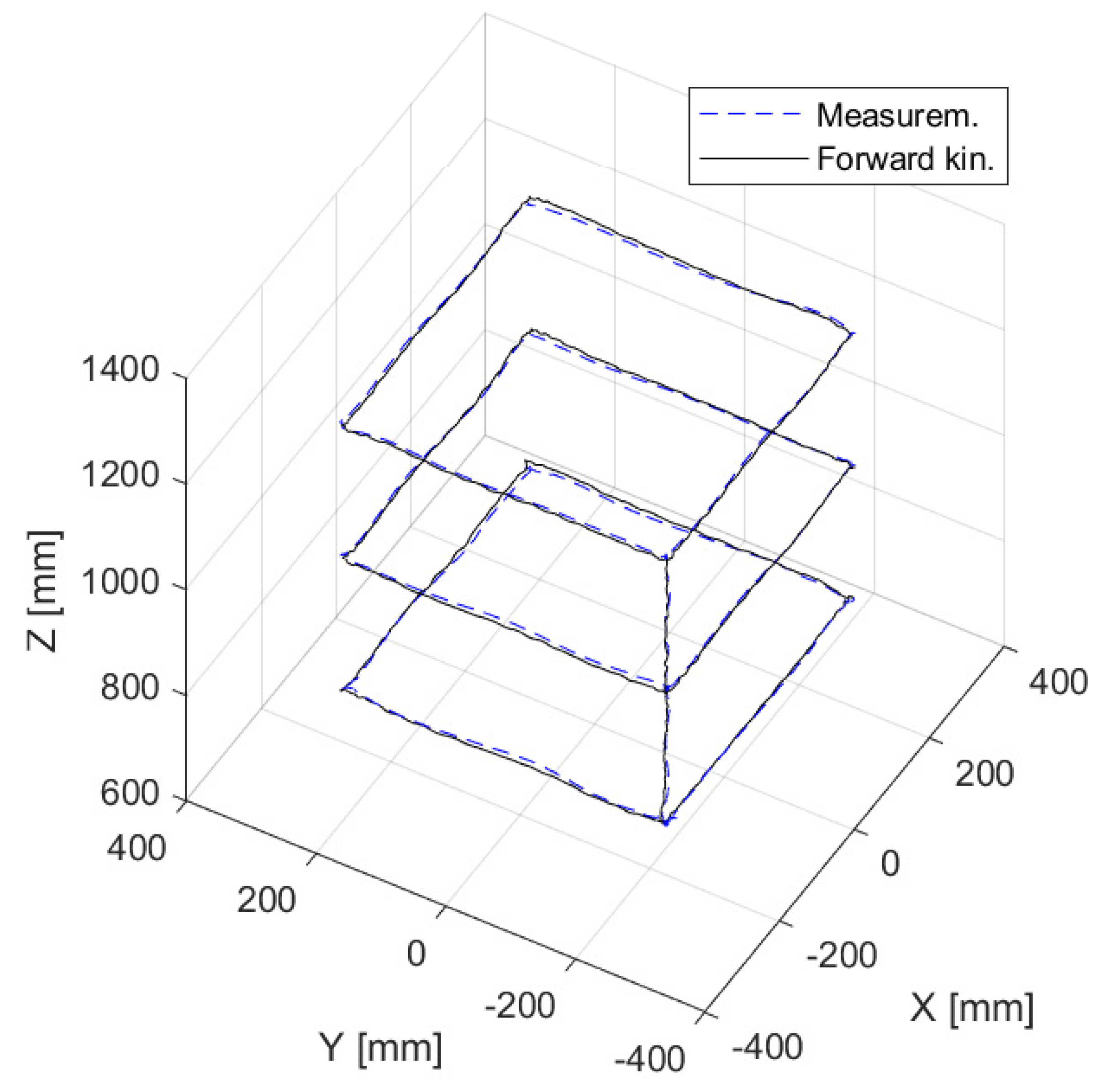
In order to guarantee that the accuracy achieved in
Figure 7 was not restricted to this scenario, a more complex trajectory was implemented throughout the workspace. In
Figure 9, the proper motion composed of three squared trajectories connected by vertical motions is depicted.
The novel comparison confirms the close matching between the two trajectories into the workspace through which the failure test passed.
4.2. Recovery Strategy
After the initial testing phase, the end-effector trajectory was compared with the Vicon data for the recovery strategy, as seen in
Figure 10. As in the previous figure, the dashed line represents the measurement data and the continuous lines are the end-effector trajectory divided into three different phases. Lastly, the dotted line in the 2D view (
Figure 10a) identifies the residual SEW.
The aim of the proposed work was to provide a recovery strategy that is feasible for real-time applications. Our method was designed to be independent of the sensors employed for the cable failure detection. Thus, in the proposed test, the cable failure event was simulated by quickly unfolding the cable to make it slack and cause it to be unable to pull the end-effector.
As previously described, the recovery approach was divided into two phases: a braking phase while moving towards the new SEW, and a linear trajectory, respectively (the black line is the circular pre-failure trajectory). The first phase, in red, shows how the end-effector moved towards the new SEW. Then, the linear trajectory drove the end-effector towards the designed SP, whose coordinates were [−0.45, −0.42, 1.2] m.
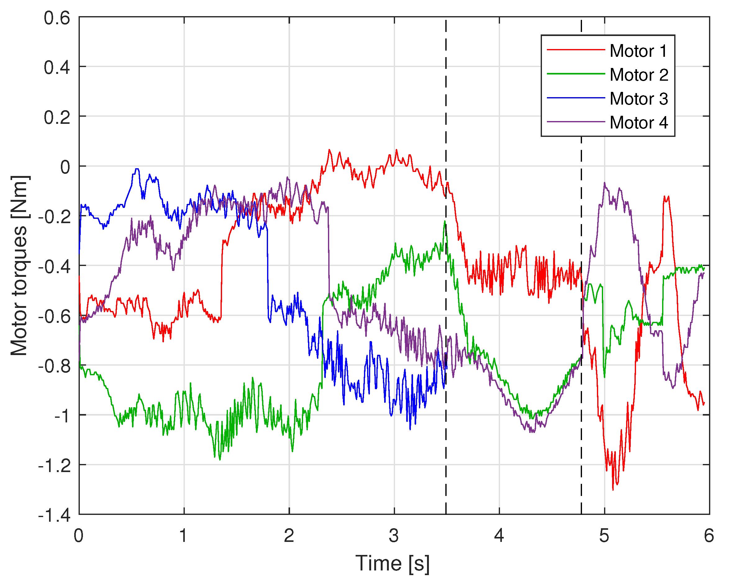
Figure 11 represents the trend of the actuator torques during the cable failure test. Two vertical dashed lines are depicted to better identify the two phases of the recovery strategy.
In the first part of the plot, the torque behavior corresponded to the movement of the end-effector actuated by the four cables. The first vertical dashed line in the figure shows the time of failure of cable 3 (t = 3.5 s). Then, the first phase of the recovery strategy began. An increase in the motor torques of the cables closest to the broken one can be observed. Indeed, they were required to sustain the end-effector and attract it to the SEW. Meanwhile, a proper constant torque was applied by motor 1, not to help the other cables to attract the end-effector into the SEW but also to prevent cable 1 from becoming slack. Conversely, the torque of the broken cable motor was not plotted because it is not meaningful. The final phase of the recovery strategy began after the second vertical dashed line. The measured torques corresponded to the linear trajectory planned to make the end-effector reach the SP. The values of motor torques exerted during the recovery guaranteed that the cable tensions remained positive and hence that the cables were taut.


