Article

Effects of Mass Change on Liquid–Liquid Phase Separation of the RNA-Binding Protein Fused in Sarcoma

1
State Key Laboratory of Electroanalytical Chemistry, Changchun Institute of Applied Chemistry, Chinese Academy of Sciences, Changchun 130022, China
2
School of Applied Chemistry and Engineering, University of Science and Technology of China, Hefei 230029, China
3
Beijing National Laboratory for Molecular Sciences, College of Chemistry and Molecular Engineering, Beijing 100871, China
4
Peking-Tsinghua Center for Life Sciences, Academy for Advanced Interdisciplinary Studies, Peking University, Beijing 100871, China
5
Department of Chemistry and Physics, Stony Brook University, Stony Brook, NY 11794-3400, USA
*
Authors to whom correspondence should be addressed.
Biomolecules 2023, 13(4), 625; https://doi.org/10.3390/biom13040625
Submission received: 21 November 2022 / Revised: 13 March 2023 / Accepted: 24 March 2023 / Published: 30 March 2023

Abstract

:
In recent years, many experimental and theoretical studies of protein liquid–liquid phase separation (LLPS) have shown its important role in the processes of physiology and pathology. However, there is a lack of definite information on the regulation mechanism of LLPS in vital activities. Recently, we found that the intrinsically disordered proteins with the insertion/deletion of a non-interacting peptide segment or upon isotope replacement could form droplets, and the LLPS states are different from the proteins without those. We believed that there is an opportunity to decipher the LLPS mechanism with the mass change perspective. To investigate the effect of molecular mass on LLPS, we developed a coarse-grained model with different bead masses, including mass 1.0, mass 1.1, mass 1.2, mass 1.3, and mass 1.5 in atomic units or with the insertion of a non-interacting peptide (10 aa) and performed molecular dynamic simulations. Consequently, we found that the mass increase promotes the LLPS stability, which is based on decreasing the z motion rate and increasing the density and the inter-chain interaction of droplets. This insight into LLPS by mass change paves the way for the regulation and relevant diseases on LLPS.

1. Introduction

Liquid–liquid phase separation (LLPS) plays an essential role in cell survival, which is a physicochemical phenomenon in which a solution of proteins and/or nucleic acids concentrates into a distinct, dense phase in equilibrium with a dilute phase depleted in macromolecules [1,2]. Although the concept of membraneless compartments inside cells such as the nucleolus were described as early as the 1830s [3], recently mounting evidence on the wide-ranging roles that biomolecular condensates, including the nucleolus, nuclear speckles, stress granules, Cajal bodies, and P bodies [4,5,6,7], are viewed as critical in regulating diverse cellular function have reignited interest in the behaviors of biological LLPS [8]. The functions of biomolecular condensates referred to as membraneless organelles (MLOs) include cell signaling, nuclear transcription, RNA splicing and processing, and DNA sensing and damage repair [3,5,6,7,9,10,11,12,13]. Importantly, dysregulation of LLPS has been associated with the pathogenesis of neurodegenerative diseases, including amyotrophic lateral sclerosis (ALS), frontotemporal dementia (FTD), and Alzheimer’s, Parkinson’s, and Huntington’s diseases [6,14,15,16,17,18]. Although there is no study which can decipher conclusively the cellular and pathologic basis of the diseases, the unifying observation of abnormal protein inclusions in postmortem tissue may suggest that one well-characterized cellular feature of neurodegenerative disease is the deposition of protein aggregates in affected brain regions [19].
Proteins that undergo LLPS tend to be the intrinsically disordered protein (IDP) or contain the intrinsically disordered region (IDR) which lacks a defined secondary structure [20]. Uversky, Dunker et al. opened the door to the investigation of IDPs [21,22], and Uversky et al. firstly proposed that IDPs serve as important drivers of intracellular LLPS based on the comprehensive assessment of protein intrinsic disorder predisposition by in silico predictors [23]. Recently, Uversky et al. developed a novel web platform named BIAPSS, which can uncover the sequence-encoded signals of proteins capable of undergoing LLPS [24]. IDRs are typically enriched in charged, polar, and/or aromatic amino acids and contain amino acids such as glycine and proline that may convey some structural information [6]. Based on the specific composition and the abundance of amino acids, IDRs can be further classified into arginine/glycine-rich (RG/RGG) domains, phenylalanine/glycine (FG) domains, and prion-like domains (PrLDs), which respectively engage in weak multivalent interactions responsible for driving phase transitions [6].
RNA-binding protein fused in sarcoma (FUS) is a canonical IDP for neurodegenerative diseases, which is mis-localized to cytoplasmic inclusions in degenerating neurons with the onset of ALS and FTD [25]. Furthermore, the FUS is an important model for investigating the LLPS behavior of IDPs/IDRs, and there are abundant studies for LLPS using the FUS model. Some functional MLOs containing FUS are modulated by the recognition of FUS to special RNA fragments [6,16,26]. Kang et al. found that the LLPS of FUS whose aggregation leads to ALS/FTD is enhanced at low concentrations for ATP but is dissolved at high concentrations [27]. In addition, the MD simulations results of Aida et al. have revealed that ATP affects LLPS of FUS by promoting both hydration and solubilization of FUS [28]. On the other hand, Levone et al. found that FUS-dependent LLPS is the requirement of the activation of the cellular DNA damage response (DDR) [11]. The studies of Lao et al. have shown in atomistic detail how phosphorylation inhibits FUS LLPS and reverses the FUS gel/solid phase toward the liquid phase [29]. Bock et al. found that N-terminal acetylation of FUS LC promotes phase separation and reduces aggregation in E. coli [30]. Yoshizawa et al. found that the importin karyopherin-beta 2/transportin-1 inhibits LLPS of FUS [31]. In addition, some studies found that environmental factors including pH, molecular crowder [32], temperature [33,34], salt concentration [35], and osmotic pressure [36,37] also affect FUS LLPS and aggregation.
At a given temperature T, higher mass leads to slower thermal motions for the beads, which shows the average effect of mass at the macroscopic level. However, it is unclear how the mass of IDP affects LLPS at the molecular level. Three common techniques to study IDPS that form condensates are solution NMR spectroscopy, small-angle X-ray scattering (SAXS), and Förster resonance energy transfer (FRET), but all of these are relatively low-resolution methods [38,39]. Due to the lack of persistent secondary structures, multiple fuzzy conformations, difficulty in aligning low-complexity regions (LCRs), of obtaining structural properties of droplets, and of choosing appropriate mutations for IDPs, our current molecular understanding of LLPS through experimental approaches is still restrictive [39]. In comparison, molecular dynamics (MD) simulations provide an insightful route to characterize the dynamics of LLPS on atomic and microsecond scales and to generate detailed information on conformational ensembles of IDPs and the contacts formed within a condensate composed of IDP molecules [40]. Best et al. developed a coarse-grained simulation method to determine thermodynamic phase diagrams of IDPs [41] and characterized phase boundaries and material properties for 20 diverse IDP sequences [42]. Additionally, Best et al. used the coarse-grained models to determine the hydrophobicity scale, which can predict LLPS of a given protein and confirms the importance of pi–pi interactions in LLPS [43]. Uversky et al. demonstrated that conformational dynamics of IDPs can rewire the regulatory networks by combining experimental measurements with coarse-grained simulations [44]. There are two ways that the molecular mass of an IDP would change: isotope replacement or the insertion/deletion of a non-interacting peptide segment. In this study, both methods are applied. So, to elucidate the accurate mass effect on LLPS at molecular level, we develop different models based on the two segments of FUS, including a prion-like domain of 50-residue length and an RGG domain of 50-residue length and perform coarse-grained MD simulations. Our results provide the detailed mechanism how IDPs mass change affects the LLPS behaviors of FUS segments.

2. Materials and Methods

2.1. Simulation System

To our knowledge, there is an effect of chain length on phase diagram [41], and Best et al. found that the results of the slab method and Monte Carlo method of sampling phase coexistence are in good agreement, especially for the proteins whose chain length is equal to 20 or 50 [42]. The major splicing isoform of FUS consists of 526 residues, as reported, and the intrinsically disordered domain of proteins is crucial for the formation of droplets for FUS proteins, which are prion-like domain, RGG1 domain, RGG2 domain, and RGG3 domain [45]. Considering RGG3 domain (FUS 453-501) is about 50 aa, in this study, we selected two amino acid sequences for comparison, which were truncated as 1–50 residue and 453–502 residue in the FUS amino acid sequence, denoted as PLD and RGG, respectively. Next, molecular dynamics simulations with coarse-grained and slab models [41] are used to capture the behavior of the IDPs with or without LLPS. We used the tool of SMOG website to simplify the process of transforming the PDB structure to the coarse-grained model provided for GROMACS [46]. In our coarse-grained model, each amino acid residue is represented by a single bead, using its Cα position, and all beads of a protein sequence have the same mass (shown in Figure 1) [47]. To investigate the effort of isotope labels for the behavior of IDPs in LLPS, the mass of each bead of normal protein is set as 1.00. In contrast, the bead mass of isotope-labeled protein is set as 1.20. As shown in Figure 1, normal PLD chain model (PLD 1.0), isotope-labeled PLD chain model (PLD 1.2), normal RGG chain model (RGG 1.0), and isotope-labeled RGG chain model (RGG 1.2) were treated as four simulation systems. In addition, we supplemented mass 1.1, mass 1.3, and mass 1.5 systems to verify conclusions from the comparison of the normal FUS (mass 1.0) systems and the isotope-labeled FUS (mass 1.2) systems. In each system, 200 identical FUS chains (n = 200) were added in the simulation box. Hence, the total number of beads in each system is 10,000.
In order to investigate the effect of IDPs with the insertion/deletion of a non-interacting peptide segment to LLPS from mass change perspective, we constructed four models, as shown in Figure 1, referred to as PLD-tG1, PLD-tG2, RGG-tG1, RGG-tG2. PLD-tG1, and RGG-tG1, adding 10 glycine amino acids to the end of the PLD sequence and RGG sequence. PLD-tG2 and RGG-tG2 add 5 glycine amino acids to the head and the end of both the PLD sequence and RGG sequence. In each system, 200 identical FUS chains with glycines insertion (n = 200) were added in the simulation box. Hence the total number of beads in each system is 12,000. The masses of these four models are the same as the mass 1.2 system models.
In this study, our model incorporates a potential energy function including bonded potential, 12-6 Lennard-Jones (LJ) potential, and Debye-Hückel potential to represent bonding, backbone rigidity, Van der Waals interactions as well as electrostatic interactions, where the bonded potential is classical harmonic model and is given by
U b ( r i j ) = K b ( r i j r 0 ) 2
where the bond constant K b is taken to be 20,000 kJ∙nm−2∙mol−1 and the equilibrium bond length r 0 is equal to 3.8 Å. The standard Lennard − Jones potential is given by
U L J = ε [ ( σ r ) 12 ( σ r ) 6 ]
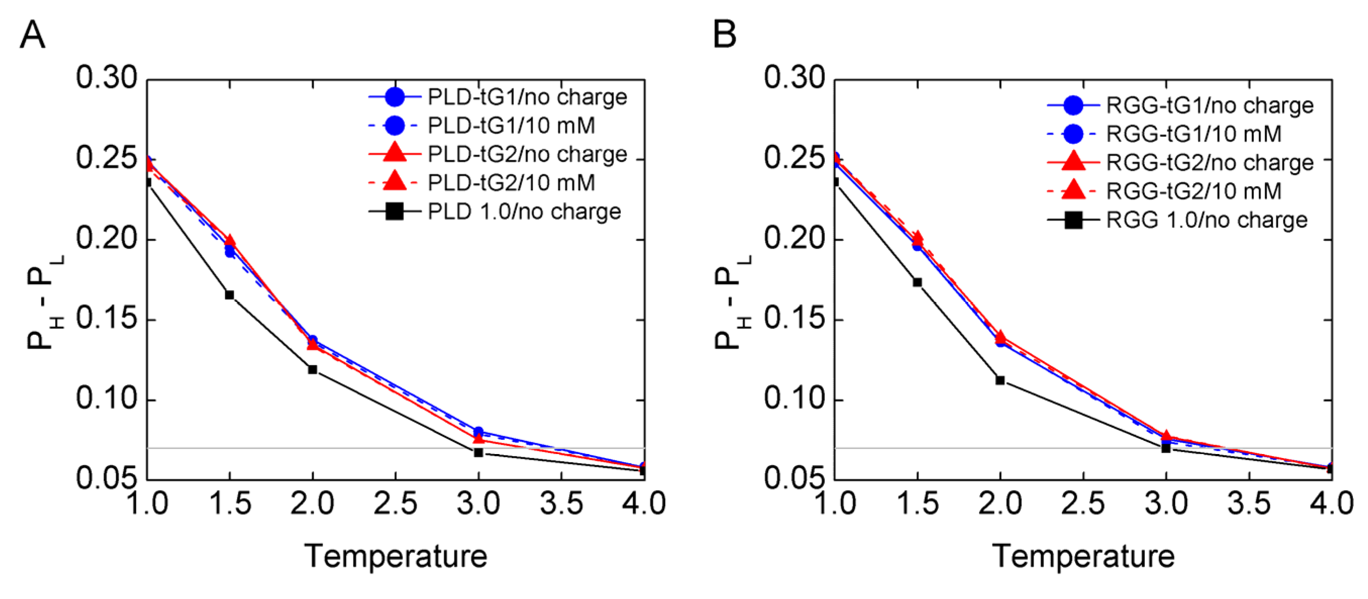
where the parameter σ is the “finite distance”, σij is the optimal distance between beads i and j that are in contact with each other. We consider the parameter σ equals a constant; that is, the σ is 10 Å (about 2.6 a, a = 3.8 Å is the mean bond length). In addition, we performed a series of Langevin dynamics simulations on isolated normal RGG and found that when the parameter ε is equal to 0.001, 0.01, 0.1 kJ/mol (σ = 1.0 nm), respectively, the head-to-tail distance (D) results are similar and show that the isolated protein chain is in the disorder state (see Supplementary Materials Figure S1). Considering our simulations are not completely quantitative, only qualitative, the energy parameter ε is set as 0.001 kJ/mol to make sure to capture the behavior of FUS chains in LLPS and LLPS disappears eventually [48]. For the glycine-inserted FUS chains, there are two ε parameters, one is the scale of LJ interaction between the residues of the FUS chains, which is set as 0.001 kJ/mol. The other is the scale of LJ interaction between an inserted residue and another residue (referred as ε-insert) and is set as 0.00001 kJ/mol, which indicates that the inserted peptide is non-interacting. We performed a series of test simulations with three ε-insert parameters for glycine-inserted FUS chains and found the ε-insert parameters as 0.0001, 0.00001 or 0.000001. The results are all similar (shown in Figure 2, Figures S2 and S3). This validated that the effect of the interaction changed by glycine-inserted peptide to LLPS is negligible.
In addition, the Debye − Hückel potential is given by
V Debye Hückel = K c o u l o m b B ( κ ) i , j q i q j exp ( κ r i j ) ϵ r i j
where Kcoulomb = 138.94 kJ∙mol−1∙nm∙e−2 is the electric conversion factor; B(κ) is the salt-dependent coefficient; κ−1 is the Debye screening length, which is directly dependent on the solvent ionic strength (IS)/salt concentration Csalt ( κ 3.2 C s a l t ); ϵ is the dielectric constant, which was set to 80 during the simulations to mimic the solvent medium (water); qi and qj are the charges of beads i and j. In our model, aspartic acid and glutamic acid have a negative charge, q = −1, and lysine and arginine have a positive charge, q = +1. Other residues were set to q = 0. Thus, the PLD chain possesses 2 negative charges and the RGG chain possesses 6 negative charges and 9 positive charges. In order to investigate the role of electrostatic interaction for the phase separation with changed beads mass, we consider two extreme conditions with one where salt concentration is 10 mM (Csalt = 0.01 M), which represents there being almost no effect of electrostatic screening, and the other where there is no charge interaction.
After the initial equilibrium (10 ns NVT and 10 ns NPT simulations), we changed the simulation box by elongating the z dimension to 300 nm (z = 300 nm) and for 10,000 bead systems shortening both the x and y to 31 nm (x = 31 nm, y = 31 nm) or for 12,000 bead systems shortening both the x and y to 34 nm (x = 34 nm, y = 34 nm) [41]. Compared with the cubic box approach [49], using slab method reduces the simulation cost and does not affect results [41,50]. Then, 5 μs long-time simulations are conducted to all FUS chains systems at multiple temperatures with two strength-of-charge interactions using constant temperature and volume with a Langevin thermostat with 2.0 fs time step and 1.0 ps−1 friction coefficient. In order to cover the overall process from LLPS to phase-separation disappearance, we used a series temperature from 100 K to 400 K (100, 150, 200, 300, and 400 K) in Gromacs. For the reduced unit in the coarse-grained model, we set the unit temperature (T0) and unit time (τ) to 100 K and 1 ns in Gromacs. As a result, the simulation temperatures correspond to 1.0, 1.5, 2.0, 3.0, and 4.0 T0, and the simulation length of each trajectory corresponds to 5000 τ. In the simulation, all the scales including the length scale, time scale, mass scale, and energy scale are based on theory and used as reduced unit, so the simulation temperature/time cannot be equal to the real temperature directly [51,52]. In order to avoid misunderstanding, we did not mention K in following figures involving the temperature.

2.2. Data Analysis

We introduced the maximum difference of local density of beads in the box to describe the extent of phase-separation. The local density of beads is determined by the proportion (Pγ = mγ/N, γ = 1…30) of the bead number (denote as mγ) of each window in the amount (N) of beads of the box, where the window is the order coordinate set by cutting the z axis into 30 windows (γ, the length of γ is 10 nm) and then clustering each bead of the specified window according to the z coordinate of the bead. For the bead density distribution function of z, we calculate the difference between the highest (PH) and the lowest (PL) values. When LLPS occurs, the protein solution emerges, and demixing and a phenome of the condensed-phase and dilute-phase coexisting in solution is observed, which can be characterized by the difference (PH-PL) of the densities of the two coexisting phases and the value greater than LLPS more obviously.
We introduced the z motion rate of the chains in each model to investigate the role of variant bead mass in the velocity perspective as the same reason to calculate the flux for the droplet boundary. In order to distinguish condensed-phase vs. dilute-phase simply based on a boundary line, we set the center of the system (condensed-phase with LLPS) at the zero point of x, y, and z axes and took the distance/displacement of each chain (center of mass (CM)) to the zero point on the z axis (|z|n = |znz0|, n = 1…200) as the coordinate of each chain. Hence, the condensed-phase is below and the dilute-phase is above for a boundary line when LLPS occurs. As the same as above, we cut the |z| into 30 windows as reaction coordinate. Each window length is 5 nm. Subsequently, the z motion rate is calculated by averaging the change rates of z coordinate of each chain in the box. The z motion rate equation is given by
v m = t 0 t m n = 1 200 ( | z n ( t m + 1 ) z n ( t m ) | ) 200 × 2000 Δ t
where t 0 is 4000 τ, t m limit is 5000 τ, z n ( t m ) is the z coordinate of the n chain at time tm, Δ t = ( t m + 1 t m ) is 0.5 τ.
The flux equation is given by
N t = n = 1 200 f ( z n ( t ) ) 0.5 τ
f ( z n ( t ) ) = { 1   ,     ( z n ( t ) ( 2750 z b u n d a r y l i n e ) ) × ( z n ( t + 1 ) ( 2750 z b u n d a r y l i n e ) ) < 0 o r   ( z n ( t ) ( 2750 + z b u n d a r y l i n e ) ) × ( z n ( t + 1 ) ( 2750 + z b u n d a r y l i n e ) ) < 0 o r   z n ( t ) × z n ( t + 1 ) < 0 0 ,   o t h e r s
where z n ( t ) is the z coordinate of the n chain at time t, and z b u n d a r y l i n e is 250 angstroms, which is the distance between the center of condensed-phase and the boundary line.
In addition, we analyzed the electrostatic interactions by calculating the amount of intra-chain electrostatic contact (Eintra) and the amount of inter-chain electrostatic contact (Einter). Eintra is defined by the number of intra-chain contacts when the pairwise (Cα-Cα) distance between residues of having opposite charge within same chain was less than 12 Å. Similarly, Einter is defined by the number of inter-chain contacts when the pairwise (Cα-Cα) distance between residues having opposite charges in different chain was less than 15 Å. Considering the charge amount of the chain for all systems and the charge environment in two salt concentration solvents, only chains containing RGG sequence and in 10 mM salt concentration solvent take possession of Eintra and Einter.

3. Results and Discussion

3.1. The Mass Effect on LLPS Stability

In order to investigate the system phase property, we firstly calculated the difference between PH and PL (PH-PL) as a function of time τ with an overall 5000 τ simulation time for all the simulations trajectories. As shown in Figures S4–S17, all the simulation models have reached equilibrium after 3000 τ. To further confirm that the systems are in equilibrium, as shown in Figure S18, we calculated the PH − PL average value of every 100 τ simulation time in last 1000 τ data and found that the PH − PL values remain stable over the last 1000 τ simulation time. So, it is safe to say that the simulation systems are in equilibrium in last 1000 τ simulation time. We analyzed the last 1000 τ trajectories, representing the ensemble average values of the equilibrated simulations. As shown in Figure 3 and Figure S19, both normal FUS chains and isotope-labeled FUS chains have a decreasing trend of PH − PL values as the temperature increases. The heavier mass FUS chains systems have a greater PH − PL value at the low temperature (LLPS occurs), which indicates that the LLPS of the heavier mass FUS chains systems are more stable. For example, Figure 3A,B suggest that the temperature of an obvious LLPS (PH − PL > 0.15) for PLD 1.0 chains without charge interaction, PLD 1.0 chains with charge interaction, PLD 1.2 chains without charge interaction, PLD 1.2 chains with charge interaction, RGG 1.0 chains without charge interaction, RGG 1.0 chains with charge interaction, RGG 1.2 chains without charge interaction, and RGG 1.2 chains with charge interaction is below 1.7 T0, 1.7 T0, 2.0 T0, 2.0 T0, 1.7 T0, 1.7 T0, 2.0 T0, and 2.0 T0, respectively. The FUS chain system’s mass increase from 1.0 to 1.2 enlarges the temperature range about 0.3 T0 for the emergence of the obvious LLPS (PH − PL > 0.15), while charge effects on LLPS are not as significant as the mass effect, as shown in Figure 3. At the same time, when the temperature increases, the PH value decreases and the PL value increases (see Figure S20). Furthermore, we found that the LLPS disappears at high temperature (critical temperature, TCr) when the density difference is negligible in the protein solution. The critical temperature TCr can be obtained by the Flory–Huggins theory or fitting by
ρ H ρ L = A ( T C r T ) β
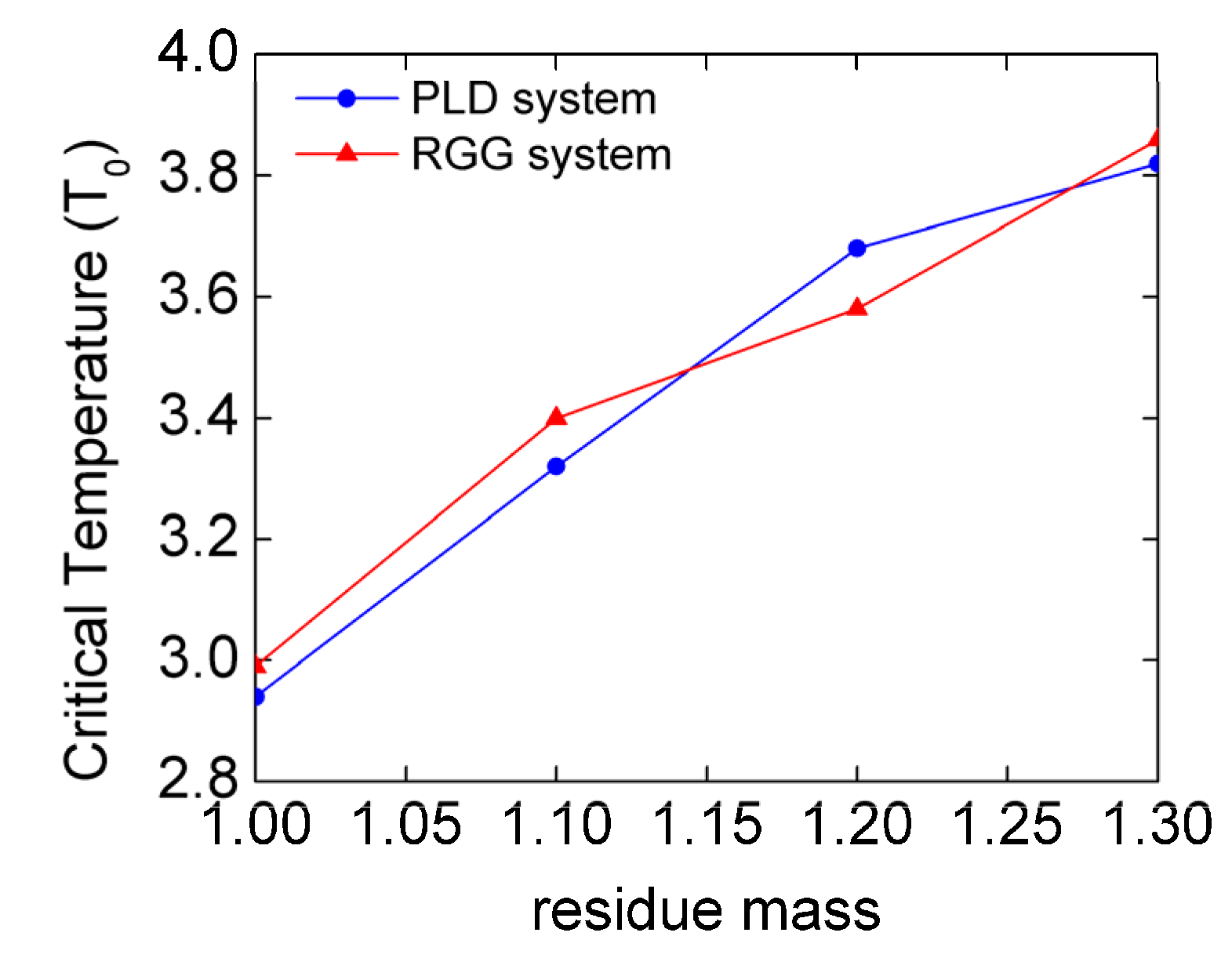
where β is the critical exponent, and A is a protein-specific fitting parameter [41]. When PH − PL = 0, the temperature of the phase diagram equals the critical temperature (TCr). However, the absolute zero point of PH − PL cannot be obtained from the simulations. Thus, we set the threshold to be 0.07. LLPS disappears when PH − PL < 0.07. In detail, the TCr value is only relevant to residue mass, regardless of the salt concentration in the models. The TCr values of PLD 1.0 chains and RGG 1.0 chains are 2.9 T0, and those of PLD 1.2 chains and RGG 1.2 chains are about 3.6 T0. Hence, it is easy to confirm that the FUS chain system’s mass increase from 1.0 to 1.2 increases the TCr by 0.7 T0. In addition, as shown in Figure 4, the critical temperature increases as the mass of the systems increases.
As shown in Figure 2, there is no obvious difference of PH − PL value changes with temperature between the FUS segments with different modes of glycine peptide insertion, while the same is true for that in different solvents. Compared with normal FUS chains, the glycine-inserted FUS chains have a greater PH − PL value at the low temperatures (LLPS occurs). This indicates that the LLPS of the glycine-inserted FUS chains are more stable. For example, Figure 2A,B suggest that the temperature of an obvious LLPS (PH − PL > 0.15) for PLD 1.0, PLD-tG1, RGG 1.0, and RGG-tG1 is below 1.7 T0, 1.9 T0, 1.7 T0, and 1.9 T0, respectively. The FUS chain with glycine insertion enlarges the temperature range about 0.2 T0 for the emergence of the obvious LLPS (PH − PL > 0.15). Additionally, The Tcr values of PLD 1.0 chains and RGG 1.0 chains are 2.9 T0, and those of PLD-tG1 and RGG-tG1 are about 3.5 T0 and 3.3 T0, respectively. In summary, both the isotope labeling and the peptide insertion lead to the mass increase and promote the LLPS stability. Thus, the isotope labeling promotes the greater LLPS stability.

3.2. The Mechanism of Mass Effect on LLPS

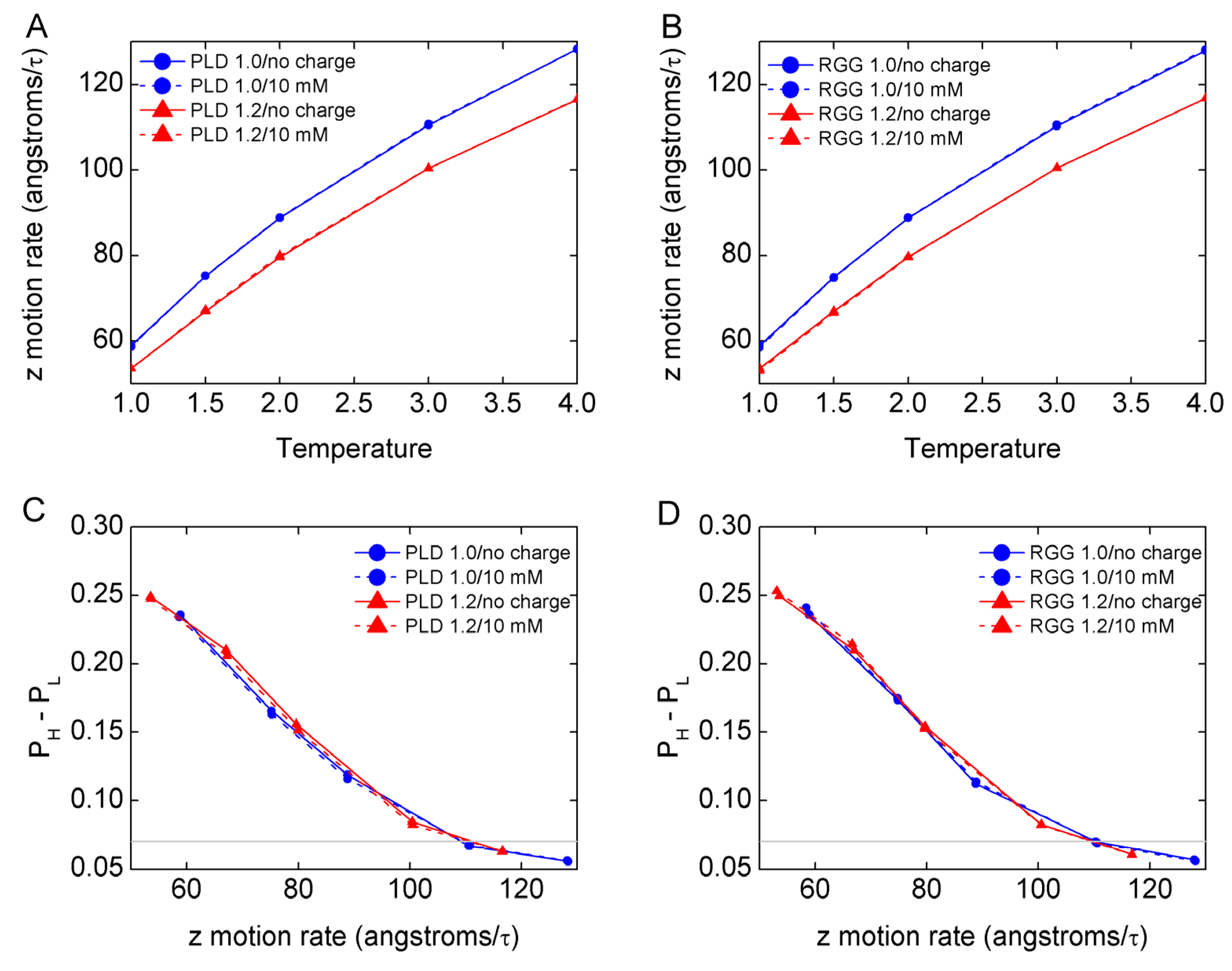
Considering that each chain undergoes the stochastic dynamics in the simulation, motion and diffusion of beads may slow down when the mass increases from 1.00 to 1.50. In this simulation, to quantify the motion on the z axis of the slab model, we calculated the average z motion rate of all the 200 chains. As shown in Figure 5 and Figure S21, the results suggest that the z motion rate increases as the temperature increases. In addition, the z motion rate of the mass of heavier FUS chains is always smaller than that of the normal FUS chains at the same temperature. For example, at 2.0 T0, the z motion rate of PLD 1.2 chains without charge is 79.6 Å/τ, lower than that of PLD 1.0 chains (88.8 Å/τ). As shown in Figure 5C,D, the PH − PL values decrease as the z motion rates increase for normal and isotope-labeled models. The results suggest that the z motion rate is strongly correlated with the stability extent of the LLPS, and lower rate of z motion favors the formation and stability of LLPS.
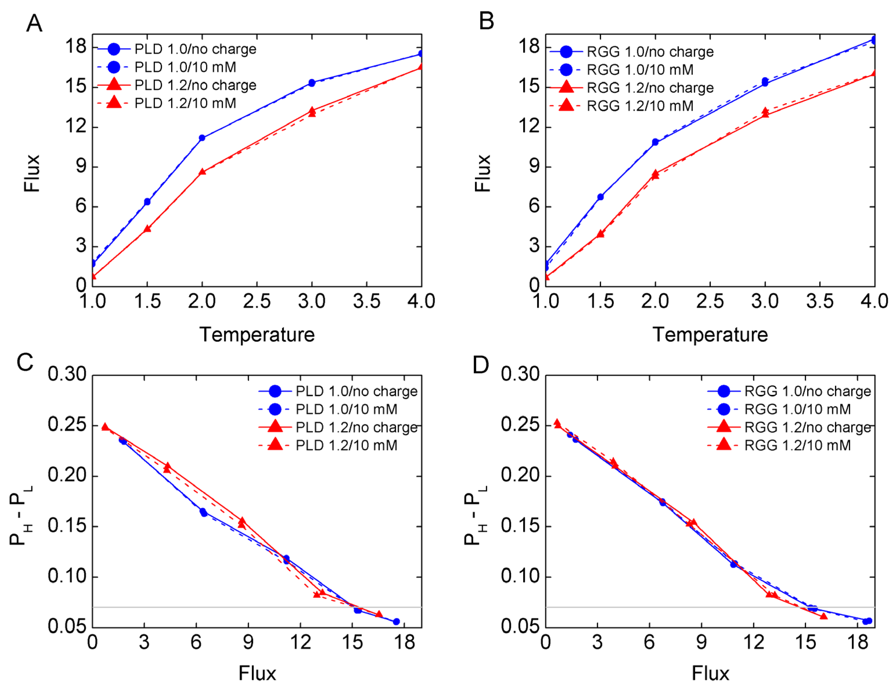
In order to quantify the diffusion of molecules between condensed-phase and dilute-phase, we calculated the average flux of the chains across the boundary line of the condensed-phase during last 1000 τ time. As shown in Figure 6A,B, the flux increases as temperature rises for all models. The flux values of isotope-labeled FUS chains are smaller than that of normal FUS chains at the same temperature. For example, at 2.0 T0, the flux of PLD 1.2 chains without charge is 8.6 chains/τ, lower than that of PLD 1.0 chains (11.2 chains/τ). As shown in Figure 6C,D, the PH − PL values decrease as the flux values increase for normal and isotope-labeled models. As shown in Figure S22, we calculated the average flux during the last 100 τ simulation time to confirm that our systems are in equilibrium and the results are reliable. As a result, the flux is strongly correlated with the stability extent of LLPS and lower flux values favor LLPS formation and stability, whose results are equivalent to the z motion rate’s.
As shown in Figure S23A,B, the results suggest that the z motion rate increases as the temperature increases, and there is no obvious difference for different inserted modes and different solvents. In addition, the z motion rate of glycine-inserted FUS chains is always smaller than that of normal FUS chains at the same temperature. For example, at 2.0 T0, the z motion rate of PLD-tG1 chains is 80.5 Å/τ, lower than that of PLD 1.0 chains (88.8 Å/τ). As shown in Figure S23C,D, the PH − PL values decrease as the z motion rates increase for glycine-inserted models, which are the same as the isotope-labeled FUS chains.
As shown in Figure S24A,B, the flux increases as the temperature rises for the glycine-inserted models. The flux values of glycine-inserted FUS chains are smaller than that of the normal FUS chains at the same temperature. For example, at 2.0 T0, the flux of PLD-tG1 chains is 9.5 chains/τ, lower than that of PLD 1.0 chains (11.2 chains/τ). As shown in Figure S24C,D, the PH − PL values decrease as the flux values increase for the glycine-inserted models.
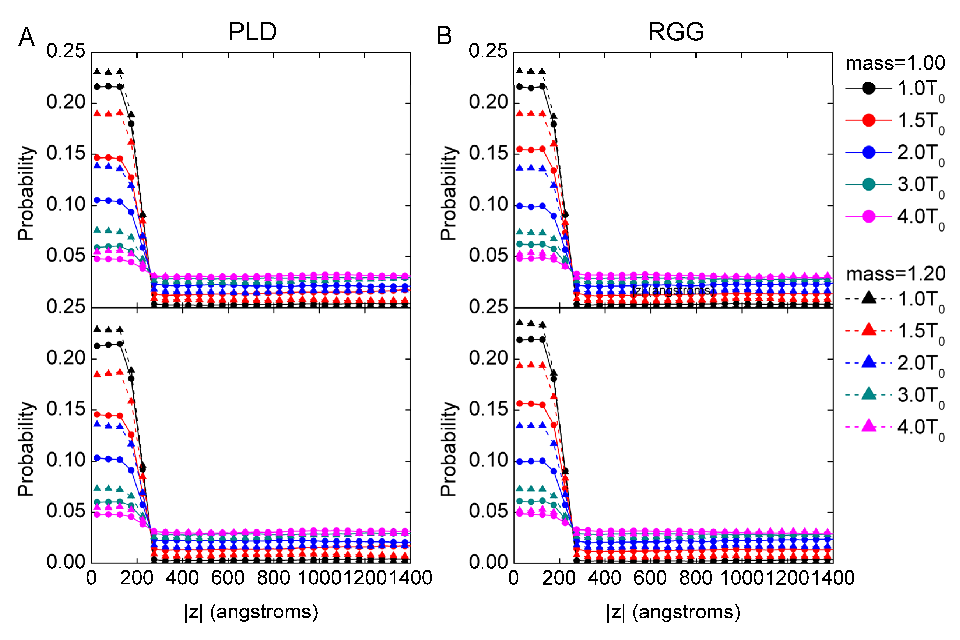
In addition, we use the distribution of probability of FUS chains as a function of displacement |z| to describe the degree of chain aggregation. As shown in Figure 7 and Figure S25, in the droplet, the probability of the mass heavier of FUS chains is greater than that of normal FUS chains, which indicates that the heavier FUS chains have more concentrated distribution than normal FUS chains at the low temperature (LLPS occurs). For example, at 1.0 T0, when |z| = 0 nm, the probability of PLD 1.2 chains is 0.23 greater than that of PLD 1.0 chains (0.21). As shown in Figure S26, the distribution of the probability of glycine-inserted FUS chains is similar to that of the isotope-labeled FUS chains and compared with normal FUS chains. We found that at the lower temperature (LLPS occurs), the probability of glycine-inserted FUS chains distributed in droplets (|z| < 25 nm) is greater than that of normal FUS chains. For example, at 1.0 T0, when |z| = 0 nm, the probability of PLD-tG1 chains is 0.23 greater than that of PLD 1.0 chains (0.21). In summary, the mass increase leads to FUS chains being more concentrated in the droplets.

3.3. The Effect of Mass Increase on the Conformation of Chains and the Electrostatic Contact

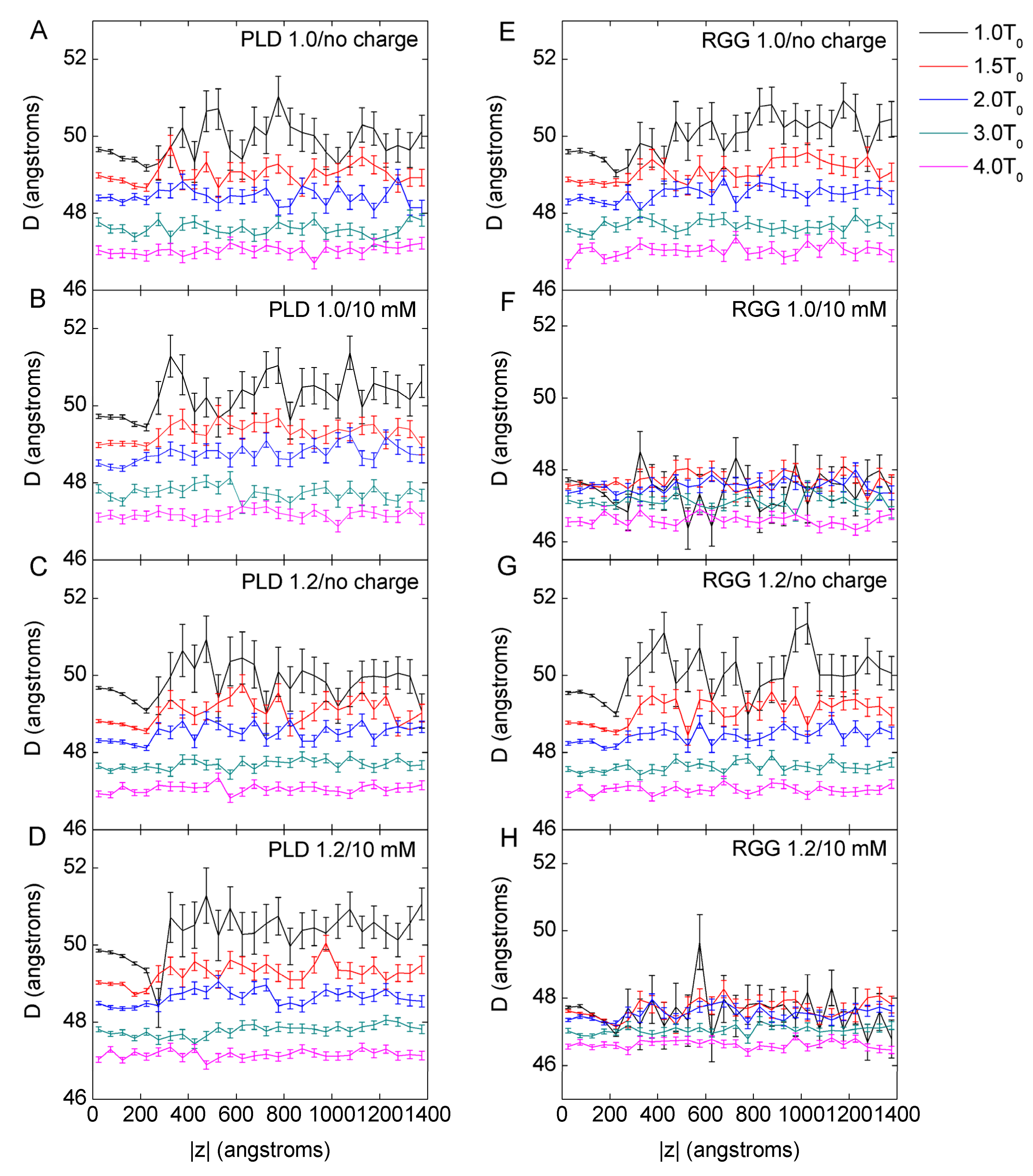
We calculated the mean end-to-end distance (D) of 200 chains to show the conformation changes at different conditions. As shown in Figure 8 and Figure S27, there is a trend that the mean D decreases as the temperature increases in normal and isotope-labeled models. The effect of the mass increases on the mean D can be negligible. This indicates that the mass of chains does not have a significant effect on the conformation of an individual molecule. Intriguingly, the mean D shows difference with different charge patterns. The PLD chains with 10 mM salt concentration solvent have a slightly greater mean D than that without charge interactions. In contrast, the RGG chains with 10 mM salt concentration solvent have a smaller mean D than that without charge interaction. The results suggest that the electrostatic interactions help RGG chains to fold a bit.
In order to distinguish the chain conformations in the condensed-phase and the dilute-phase, we calculated the distributions of D along the displacement |z|. As shown in Figure 9, there is no significant difference between normal and isotope-labeled FUS chains.
For the glycine-inserted FUS chains, we calculated the head-to-tail distance of PLD sequence or RGG sequence excluding the glycine-inserted peptide. As shown in Figure S28, the mean D decreases as the temperature increases in glycine-inserted models. In addition, PLD-tG2 and RGG-tG2 have greater mean D values than that of PLD-tG1 and RGG-tG1, respectively. This indicates that different modes of insertion influence the head-to-tail distance of the FUS chains. Comparing with normal FUS chains and isotope-labeled FUS chains, the mean D values of glycine-inserted FUS chains are greater than that of normal and isotope-labeled FUS chains at the same temperature. We believe that the difference is not caused by the mass increase. In summary, the mass increase hardly affects the mean D of FUS chains and the conformation of FUS chains.
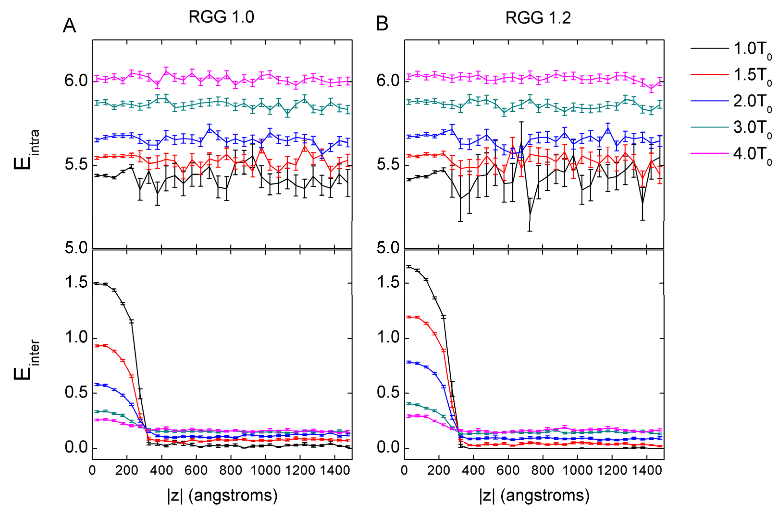
As shown in Figure 10 and Figure S29, there is no significant difference for the intra-chain electrostatic contacts (Eintra) between the normal RGG chains and the isotope-labeled RGG chains. If the conformation of the chain is curved, the Eintra value will be high. Therefore, the Eintra value correlates to the D values negatively. In the condensed phase, the Einter value correlates to the local probability of chains positively (as shown in Figure 7, Figure 10, Figures S25 and S29 and PH in Figure S20). The mass increase leads to the increase of the local probability of chains in the condensed-phase (as shown in Figure 7 and Figure S25 and PH in Figure S20). As a result, in the condensed-phase, the Einter values of the isotope-labeled RGG chains are higher than that of the normal RGG chains. For example, Einter of RGG 1.2 chains at |z| = 0 is 1.62 (T = 1.0 T0), and by contrast, that of RGG 1.0 chains is 1.49.
As shown in Figure S30, there is no significant difference for the intra-chain electrostatic contacts (Eintra) and inter-chain (Einter) electrostatic contacts between RGG-tG1 chains and RGG-tG2 chains. However, compared with the normal RGG chains and the isotope-labeled RGG chains, both the intra-chain (Eintra) and inter-chain (Einter) electrostatic contacts of RGG-tG1 and RGG-tG2 are smaller. For example, at 1.0 T0, when |z| = 0 nm, Eintra of RGG-tG1 is 4.32 smaller than that of RGG 1.2 chains (5.42), Einter of RGG-tG1 is 1.21 smaller than that of RGG 1.2 chains (1.62). We believe that the difference is not caused by the mass increase. Considering that the critical temperature of LLPS for RGG-tG chains is greater than that of RGG 1.0 chains and smaller than that of RGG 1.2 chains, we speculated that the electrostatic contact increase is not the main cause of the increased LLPS stability.

4. Conclusions

In this study we performed Langevin dynamics simulations to gain insight into the effects and the mechanism of FUS chain mass increase in LLPS. The study was inspired by one of our observations during NMR sample preparation, in which 15N, 13C, 2H-isotope-labeled FUS RGG and another aggregation-prone protein exhibited greater tendency to coacervate than unlabeled protein of the same concentration under the same buffer conditions and temperature. Our simulation results suggest that the mass increase of FUS chain promotes the level of LLPS stability, but different mass increase methods have different devotion to LLPS stability. For the critical transition temperature (TCr) where the LLPS start to emerge, the value of RGG 1.2 chains is 0.7 T0 higher than that of RGG 1.0 chains, while the value of RGG-tG1 is 0.4 T0 higher than that of RGG 1.0 chains. Based on our simulations, the details of how the FUS chain mass change affects the behavior of LLPS at various temperatures and ionic strength are vividly revealed at the molecular level. We found that, in the same environment, the z motion rate of chains of the mass 1.2 system and glycine-inserted system is lower than that of the mass 1.0 system, and the flux of the mass 1.2 system and glycine-inserted system is lower than that of the mass 1.0 system. Therefore, lower z motion rate and lower flux are beneficial to LLPS stability. Furthermore, using the distribution of probability of FUS chains as a function of displacement |z|, the results reveal that the mass increase will increase the degree of chain aggregation at the same temperature, and the chains of the mass 1.2 system and glycine-inserted system both are more concentrated than that of the mass 1.0 system. The mass increase hardly affects the head-to-tail distance (D) of FUS chains. In addition, we have noted that the mass increase by the isotope replacement is favorable to strengthen the inter-chain electrostatic contacts in the condensed-phase, hardly affect the intra-chain electrostatic contacts and the head-to-tail distance of the chains. The effect of the mass increase by glycine insertion on the intra-chain electrostatic contact and the inter-chain electrostatic contact is fuzzy and will be studied in the future. We believe that FUS chain mass increase leads to the increase of the inter-chain electrostatic contact from more concentrated distribution of FUS chains, while the electrostatic contact increase is not the main cause for increased LLPS stability. Consequently, we believe that the mass increase promotes the LLPS stability, which is based on decreasing the z motion rate, increasing the density and the inter-chain interaction of droplets.
Our findings highlight the importance of residue mass change of IDPs on LLPS. Such residue mass change often emerges in the NMR experiments used to explore the information on structures of IDPs. In our study, these changed mass FUS models may provide enlightenment towards understanding the roles of isotope-labeling effects in modulating LLPS. In addition, it is helpful to test more systems with simulation and to elaborate results from the IDP chain mass perspective for investigating the mechanism of LLPS. This may pave the way for ameliorating phase-separation-related pathologies, which will be our future work direction.

Supplementary Materials

The following supporting information can be downloaded at: https://www.mdpi.com/article/10.3390/biom13040625/s1, Figure S1: Head-to-tail distance (D) of RGG with different parameters ε (σ = 1.0 nm, ε = 0.001, 0.01, 0.1, 0.8 kJ/mol); Figure S2: PH − PL of PLD-tG (A) and RGG-tG (B) in different solvents changes with temperature when ε-insert = 0.0001 kJ/mol. The PH and PL values are calculated with the last 1000 τ simulation data as PH − PL of all the simulations reaches equilibrium after 3000 τ. The gray line is PH − PL = 0.07; Figure S3: PH − PL of PLD-tG (A) and RGG-tG (B) in different solvents changes with temperature when ε-insert = 0.000001 kJ/mol. The PH and PL values are calculated with the last 1000 τ simulation data as PH − PL of all the simulations reaches equilibrium after 3000 τ. The gray line is PH − PL = 0.07; Figure S4: PH − PL of PLD-tG1 as a function of simulation time. The upper panel shows the simulations without charge interactions (no charge); the bottom panel shows the simulations at 10 mM salt concentration; Figure S5: PH − PL of PLD-tG2 as a function of simulation time. The upper panel shows the simulations without charge interactions (no charge); the bottom panel shows the simulations at 10 mM salt concentration; Figure S6: PH − PL of RGG-tG1 as a function of simulation time. The upper panel shows the simulations without charge interactions (no charge); the bottom panel shows the simulations at 10 mM salt concentration; Figure S7: PH − PL of RGG-tG2 as a function of simulation time. The upper panel shows the simulations without charge interactions (no charge); the bottom panel shows the simulations at 10 mM salt concentration; Figure S8: PH − PL of PLD 1.0 as a function of simulation time. The upper panel shows the simulations without charge interactions (no charge); the bottom panel shows the simulations at 10mM salt concentration; Figure S9: PH − PL of PLD 1.1 as a function of simulation time. The upper panel shows the simulations without charge interactions (no charge); the bottom panel shows the simulations at 10 mM salt concentration; Figure S10: PH − PL of PLD 1.2 as a function of simulation time. The upper panel shows the simulations without charge interactions (no charge); the bottom panel shows the simulations at 10mM salt concentration; Figure S11: PH − PL of PLD 1.3 as a function of simulation time. The upper panel shows the simulations without charge interactions (no charge); the bottom panel shows the simulations at 10 mM salt concentration; Figure S12: PH − PL of PLD 1.5 as a function of simulation time. The upper panel shows the simulations without charge interactions (no charge); the bottom panel shows the simulations at 10 mM salt concentration; Figure S13: PH − PL of RGG 1.0 as a function of simulation time. The upper panel shows the simulations without charge interactions (no charge); the bottom panel shows the simulations at 10mM salt concentration; Figure S14: PH − PL of RGG 1.1 as a function of simulation time. The upper panel shows the simulations without charge interactions (no charge); the bottom panel shows the simulations at 10 mM salt concentration; Figure S15: PH − PL of RGG 1.2 as a function of simulation time. The upper panel shows the simulations without charge interactions (no charge); the bottom panel shows the simulations at 10mM salt concentration; Figure S16: PH − PL of RGG 1.3 as a function of simulation time. The upper panel shows the simulations without charge interactions (no charge); the bottom panel shows the simulations at 10 mM salt concentration; Figure S17: PH − PL of RGG 1.5 as a function of simulation time. The upper panel shows the simulations without charge interactions (no charge); the bottom panel shows the simulations at 10 mM salt concentration; Figure S18: PH − PL average as a function of simulation time. Every point represents the PH − PL average value of 100 τ simulation time; Figure S19: PH − PL of PLD (A) and RGG (B) with bead mass 1.1, 1.3, and 1.5 in different solvents changes with temperature. The PH and PL values are calculated with the last 1000 τ simulation data as PH − PL of all the simulations reaches equilibrium after 3000 τ (see Supplementary Materials). The gray line is PH − PL = 0.07; Figure S20: Phase diagrams of PLD (A) and RGG (B) with PH and PL as a function of temperature. (A) Phase diagrams of PLD 1.0 and PLD 1.2 at different solvents. (B) Phase diagrams of RGG 1.0 and RGG 1.2 at different solvents. Here, PH and PL are the highest and the lowest points of FUS segment residue distribution along the |z| axis; Figure S21: The z motion rate of PLD (A) and RGG (B) with bead mass 1.1, 1.3, and 1.5 in different solvents changes with temperature. The z motion rates are calculated by averaging 200 chains in the box with the last 1000 τ simulation data; Figure S22: The flux of last 100 τ on the boundary line. (A) The flux of PLD 1.0 and PLD 1.2 in different solvents changes with temperature. (B) The flux of RGG 1.0 and RGG 1.2 in different solvents changes with temperature. (C) PH − PL of PLD 1.0 and PLD 1.2 in different solvents changes with flux. (D) PH − PL of RGG 1.0 and RGG 1.2 in different solvents changes with flux. The fluxes are calculated by averaging the last 100 τ simulation data, and the boundary line is |z| = 25 nm. The gray line is PH − PL = 0.07; Figure S23: The z motion rate of PLD-tG (A) and RGG-tG (B) in different solvents changes with temperature; PH − PL of PLD-tG (C) and RGG-tG (D) in different solvents changes with z motion rate. The z motion rates are calculated by averaging 200 chains in the box with the last 1000 τ simulation data. The gray line is PH − PL = 0.07; Figure S24: The flux on the boundary line. (A) The flux of PLD-tG in different solvents changes with temperature. (B) The flux of RGG-tG in different solvents changes with temperature. (C) PH − PL of PLD-tG in different solvents changes with flux. (D) PH − PL of RGG-tG in different solvents changes with flux. The fluxes are calculated by averaging the last 1000 τ simulation data, and the boundary line is |z| = 25 nm. The gray line is PH − PL = 0.07; Figure S25: The distribution of probability of PLD (A) and RGG (B) with bead mass 1.1 and 1.3 as a function of displacement |z|. Data without charges and at 10mM salt concentration solvent are shown in the up panels and the bottom panels, respectively. The probability is the average value of window along |z| during the last 1000 τ simulation data; Figure S26: The distribution of probability of PLD-tG (A) and RGG-tG (B) as a function of displacement |z|. Data without charges and at 10 mM salt concentration solvent are shown in the up panels and the bottom panels, respectively. The probability is the average value of window along |z| during the last 1000 τ simulation data; Figure S27: Head-to-tail distance (D) of PLD (A) and RGG (B) chains with bead mass 1.1, 1.3 and 1.5 as a function of temperature. The D value is calculated by the mean value of the 200 chains in the system during the last 1000 τ simulation data; Figure S28: Head-to-tail distance (D) of PLD-tG (A) and RGG-tG (B) chains as a function of temperature. The D value is calculated by the mean value of the 200 chains in the system during the last 1000 τ simulation data; Figure S29: Mean number intra-chain (Eintra) of and inter-chain (Einter) electrostatic contacts of RGG 1.1 (A) and RGG 1.3 (B) as a function of |z|. Average and standard error values during the last 1000 τ simulation data are illustrated in this figure; Figure S30: Mean number intra-chain (Eintra) and inter-chain (Einter) electrostatic contacts of RGG-tG1 (A) and RGG-tG2 (B) as a function of |z|. Average and standard error values during the last 1000 τ simulation data are illustrated in this figure.

Author Contributions

Conceptualization, C.T., J.W. and W.-T.C.; methodology, W.D., J.W. and W.-T.C.; analysis, W.D., J.W. and W.-T.C.; writing—original draft preparation, W.D., J.W. and W.-T.C.; writing—review and editing, W.D., J.W., W.-T.C., C.T. and E.W. All authors have read and agreed to the published version of the manuscript.

Funding

W.D., E.W., C.T. and W.-T.C. are funded by National Natural Science Foundation of China (Grant Nos. 32171244, 12234019, 21721003), Youth Innovation Promotion Association CAS (Grant No. 2020231), and Jilin Province Science and Technology Development Plan (Grant No. 20200301009RQ).

Institutional Review Board Statement

Not applicable.

Informed Consent Statement

Not applicable.

Data Availability Statement

Not applicable.

Acknowledgments

W.D. and W.-T.C. thank the Network and Computing Center, Changchun Institute of Applied Chemistry, Chinese Academy of Science and the Computing Center of Jilin Province for computational support.

Conflicts of Interest

The authors declare no conflict of interest.

References

  1. An, H.; de Meritens, C.R.; Shelkovnikova, T.A. Connecting the “dots”: RNP granule network in health and disease. Biochim. Biophys. Acta-Mol. Cell Res. 2021, 1868, 119058. [Google Scholar] [CrossRef] [PubMed]
  2. Murthy, A.C.; Fawzi, N.L. The (un)structural biology of biomolecular liquid-liquid phase separation using NMR spectroscopy. J. Biol. Chem. 2020, 295, 2375–2384. [Google Scholar] [CrossRef] [PubMed] [Green Version]
  3. Alberti, S.; Gladfelter, A.; Mittag, T. Considerations and Challenges in Studying Liquid-Liquid Phase Separation and Biomolecular Condensates. Cell 2019, 176, 419–434. [Google Scholar] [CrossRef] [Green Version]
  4. Sawner, A.S.; Ray, S.; Yadav, P.; Mukherjee, S.; Panigrahi, R.; Poudyal, M.; Patel, K.; Ghosh, D.; Kummerant, E.; Kumar, A.; et al. Modulating alpha-Synuclein Liquid-Liquid Phase Separation. Biochemistry 2021, 60, 3676–3696. [Google Scholar] [CrossRef]
  5. Spegg, V.; Altmeyer, M. Biomolecular condensates at sites of DNA damage: More than just a phase. DNA Repair 2021, 106, 103179. [Google Scholar] [CrossRef] [PubMed]
  6. Mann, J.R.; Donnelly, C.J. RNA modulates physiological and neuropathological protein phase transitions. Neuron 2021, 109, 2663–2681. [Google Scholar] [CrossRef]
  7. Sehgal, P.B.; Westley, J.; Lerea, K.M.; DiSenso-Browne, S.; Etlinger, J.D. Biomolecular condensates in cell biology and virology: Phase-separated membraneless organelles (MLOs). Anal. Biochem. 2020, 597, 113691. [Google Scholar] [CrossRef]
  8. Garaizar, A.; Sanchez-Burgos, I.; Collepardo-Guevara, R.; Espinosa, J.R. Expansion of Intrinsically Disordered Proteins Increases the Range of Stability of Liquid-Liquid Phase Separation. Molecules 2020, 25, 4705. [Google Scholar] [CrossRef]
  9. Vodnala, M.; Choi, E.B.; Fong, Y.W. Low complexity domains, condensates, and stem cell pluripotency. World J. Stem Cells 2021, 13, 416–438. [Google Scholar] [CrossRef]
  10. Reber, S.; Jutzi, D.; Lindsay, H.; Devoy, A.; Mechtersheimer, J.; Levone, B.R.; Domanski, M.; Bentmann, E.; Dormann, D.; Muhlemann, O.; et al. The phase separation-dependent FUS interactome reveals nuclear and cytoplasmic function of liquid-liquid phase separation. Nucleic Acids Res. 2021, 49, 7713–7731. [Google Scholar] [CrossRef]
  11. Levone, B.R.; Lenzken, S.C.; Antonaci, M.; Maiser, A.; Rapp, A.; Conte, F.; Reber, S.; Mechtersheimer, J.; Ronchi, A.E.; Muhlemann, O.; et al. FUS-dependent liquid-liquid phase separation is important for DNA repair initiation. J. Cell Biol. 2021, 220, e202008030. [Google Scholar] [CrossRef] [PubMed]
  12. Su, J.M.; Wilson, M.Z.; Samuel, C.E.; Ma, D. Formation and Function of Liquid-Like Viral Factories in Negative-Sense Single-Stranded RNA Virus Infections. Viruses 2021, 13, 126. [Google Scholar] [CrossRef] [PubMed]
  13. Noda, N.N.; Wang, Z.; Zhang, H. Liquid-Liquid phase separation in autophagy. J. Cell Biol. 2020, 219, 1–13. [Google Scholar] [CrossRef] [PubMed]
  14. Peng, Q.; Tan, S.M.; Xia, L.Z.; Wu, N.Y.; Oyang, L.; Tang, Y.Y.; Su, M.; Luo, X.; Wang, Y.; Sheng, X.W.; et al. Phase separation in Cancer: From the Impacts and Mechanisms to Treatment potentials. Int. J. Biol. Sci. 2022, 18, 5103–5122. [Google Scholar] [CrossRef] [PubMed]
  15. Milicevic, K.; Rankovic, B.; Andjus, P.R.; Bataveljic, D.; Milovanovic, D. Emerging Roles for Phase Separation of RNA-Binding Proteins in Cellular Pathology of ALS. Front. Cell Dev. Biol. 2022, 10, 840256. [Google Scholar] [CrossRef]
  16. Yoneda, R.; Ueda, N.; Kurokawa, R. m(6)A Modified Short RNA Fragments Inhibit Cytoplasmic TLS/FUS Aggregation Induced by Hyperosmotic Stress. Int. J. Mol. Sci. 2021, 22, 11014. [Google Scholar] [CrossRef] [PubMed]
  17. Darling, A.L.; Shorter, J. Combating deleterious phase transitions in neurodegenerative disease. Biochim. Biophys. Acta-Mol. Cell Res. 2021, 1868, 118984. [Google Scholar] [CrossRef]
  18. Farina, S.; Esposito, F.; Battistoni, M.; Biamonti, G.; Francia, S. Post-Translational Modifications Modulate Proteinopathies of TDP-43, FUS and hnRNP-A/B in Amyotrophic Lateral Sclerosis. Front. Mol. Biosci. 2021, 8, 693325. [Google Scholar] [CrossRef]
  19. Hayashi, Y.; Ford, L.K.; Fioriti, L.; McGurk, L.; Zhang, M. Liquid-Liquid Phase Separation in Physiology and Pathophysiology of the Nervous System. J. Neurosci. 2021, 41, 834–844. [Google Scholar] [CrossRef]
  20. Lin, Y.-H.; Song, J.; Forman-Kay, J.D.; Chan, H.S. Random-phase-approximation theory for sequence-dependent, biologically functional liquid-liquid phase separation of intrinsically disordered proteins. J. Mol. Liq. 2017, 228, 176–193. [Google Scholar] [CrossRef] [Green Version]
  21. Uversky, V.N. Per aspera ad chaos: A personal journey to the wonderland of intrinsic disorder. Biochem. J. 2021, 478, 3015–3024. [Google Scholar] [CrossRef] [PubMed]
  22. Dunker, A.K.; Lawson, J.D.; Brown, C.J.; Williams, R.M.; Romero, P.; Oh, J.S.; Oldfield, C.J.; Campen, A.M.; Ratliff, C.M.; Hipps, K.W.; et al. Intrinsically disordered protein. J. Mol. Graph. Model. 2001, 19, 26–59. [Google Scholar] [CrossRef] [PubMed] [Green Version]
  23. Uversky, V.N.; Kuznetsova, I.M.; Turoverov, K.K.; Zaslavsky, B. Intrinsically disordered proteins as crucial constituents of cellular aqueous two phase systems and coacervates. FEBS Lett. 2015, 589, 15–22. [Google Scholar] [CrossRef] [PubMed] [Green Version]
  24. Badaczewska-Dawid, A.E.; Uversky, V.N.; Potoyan, D.A. BIAPSS: A Comprehensive Physicochemical Analyzer of Proteins Undergoing Liquid-Liquid Phase Separation. Int. J. Mol. Sci. 2022, 23, 6204. [Google Scholar] [CrossRef] [PubMed]
  25. Portz, B.; Lee, B.L.; Shorter, J. FUS and TDP-43 Phases in Health and Disease. Trends Biochem. Sci. 2021, 46, 550–563. [Google Scholar] [CrossRef] [PubMed]
  26. Ishiguro, A.; Ishihama, A. Essential Roles and Risks of G-Quadruplex Regulation: Recognition Targets of ALS-Linked TDP-43 and FUS. Front. Mol. Biosci. 2022, 9, 957502. [Google Scholar] [CrossRef] [PubMed]
  27. Kang, J.; Lim, L.Z.; Song, J.X. ATP enhances at low concentrations but dissolves at high concentrations liquid-liquid phase separation (LLPS) of ALS/FTD-causing FUS. Biochem. Biophys. Res. Commun. 2018, 504, 545–551. [Google Scholar] [CrossRef]
  28. Aida, H.; Shigeta, Y.; Harada, R. The role of ATP in solubilizing RNA-binding protein fused in sarcoma. Proteins 2022, 90, 1606–1612. [Google Scholar] [CrossRef]
  29. Lao, Z.; Dong, X.; Liu, X.; Li, F.; Chen, Y.; Tang, Y.; Wei, G. Insights into the Atomistic Mechanisms of Phosphorylation in Disrupting Liquid-Liquid Phase Separation and Aggregation of the FUS Low-Complexity Domain. J. Chem. Inf. Model 2022, 62, 3227–3238. [Google Scholar] [CrossRef]
  30. Bock, A.S.; Murthy, A.C.; Tang, W.S.; Jovic, N.; Shewmaker, F.; Mittal, J.; Fawzi, N.L. N-terminal acetylation modestly enhances phase separation and reduces aggregation of the low-complexity domain of RNA-binding protein fused in sarcoma. Protein Sci. 2021, 30, 1337–1349. [Google Scholar] [CrossRef]
  31. Yoshizawa, T.; Ali, R.; Jiou, J.; Fung, H.Y.J.; Burke, K.A.; Kim, S.J.; Lin, Y.; Peeples, W.B.; Saltzberg, D.; Soniat, M.; et al. Nuclear Import Receptor Inhibits Phase Separation of FUS through Binding to Multiple Sites. Cell 2018, 173, 693–705.e22. [Google Scholar] [CrossRef] [Green Version]
  32. Kaur, T.; Alshareedah, I.; Wang, W.; Ngo, J.; Moosa, M.M.; Banerjee, P.R. Molecular Crowding Tunes Material States of Ribonucleoprotein Condensates. Biomolecules 2019, 9, 71. [Google Scholar] [CrossRef] [PubMed] [Green Version]
  33. Dong, X.; Bera, S.; Qiao, Q.; Tang, Y.; Lao, Z.; Luo, Y.; Gazit, E.; Wei, G. Liquid-Liquid Phase Separation of Tau Protein Is Encoded at the Monomeric Level. J. Phys. Chem. Lett. 2021, 12, 2576–2586. [Google Scholar] [CrossRef]
  34. Dignon, G.L.; Zheng, W.; Kim, Y.C.; Mittal, J. Temperature-Controlled Liquid-Liquid Phase Separation of Disordered Proteins. ACS Cent. Sci. 2019, 5, 821–830. [Google Scholar] [CrossRef] [PubMed] [Green Version]
  35. Maity, H.; Baidya, L.; Reddy, G. Salt-Induced Transitions in the Conformational Ensembles of Intrinsically Disordered Proteins. J. Phys. Chem. B 2022, 126, 5959–5971. [Google Scholar] [CrossRef] [PubMed]
  36. Li, S.J.; Yoshizawa, T.; Yamazaki, R.; Fujiwara, A.; Kameda, T.; Kitahara, R. Pressure and Temperature Phase Diagram for Liquid-Liquid Phase Separation of the RNA-Binding Protein Fused in Sarcoma. J. Phys. Chem. B 2021, 125, 6821–6829. [Google Scholar] [CrossRef]
  37. Kitahara, R.; Yamazaki, R.; Ide, F.; Li, S.J.; Shiramasa, Y.; Sasahara, N.; Yoshizawa, T. Pressure-Jump Kinetics of Liquid-Liquid Phase Separation: Comparison of Two Different Condensed Phases of the RNA-Binding Protein, Fused in Sarcoma. J. Am. Chem. Soc. 2021, 143, 19697–19702. [Google Scholar] [CrossRef]
  38. Burke, K.A.; Janke, A.M.; Rhine, C.L.; Fawzi, N.L. Residue-by-Residue View of In Vitro FUS Granules that Bind the C-Terminal Domain of RNA Polymerase II. Mol. Cell 2015, 60, 231–241. [Google Scholar] [CrossRef] [Green Version]
  39. Bari, K.J.; Prakashchand, D.D. Fundamental Challenges and Outlook in Simulating Liquid-Liquid Phase Separation of Intrinsically Disordered Proteins. J. Phys. Chem. Lett. 2021, 12, 1644–1656. [Google Scholar] [CrossRef]
  40. Zheng, W.; Dignon, G.L.; Jovic, N.; Xu, X.; Regy, R.M.; Fawzi, N.L.; Kim, Y.C.; Best, R.B.; Mittal, J. Molecular Details of Protein Condensates Probed by Microsecond Long Atomistic Simulations. J. Phys. Chem. B 2020, 124, 11671–11679. [Google Scholar] [CrossRef]
  41. Dignon, G.L.; Zheng, W.; Kim, Y.C.; Best, R.B.; Mittal, J. Sequence determinants of protein phase behavior from a coarse-grained model. PLoS Comput. Biol. 2018, 14, e1005941. [Google Scholar] [CrossRef] [PubMed] [Green Version]
  42. Dignon, G.L.; Zheng, W.; Best, R.B.; Kim, Y.C.; Mittal, J. Relation between single-molecule properties and phase behavior of intrinsically disordered proteins. Proc. Natl. Acad Sci. USA 2018, 115, 9929–9934. [Google Scholar] [CrossRef] [PubMed] [Green Version]
  43. Dannenhoffer-Lafage, T.; Best, R.B. A Data-Driven Hydrophobicity Scale for Predicting Liquid-Liquid Phase Separation of Proteins. J. Phys. Chem. B 2021, 125, 4046–4056. [Google Scholar] [CrossRef]
  44. Lin, X.; Kulkarni, P.; Bocci, F.; Schafer, N.P.; Roy, S.; Tsai, M.Y.; He, Y.; Chen, Y.; Rajagopalan, K.; Mooney, S.M.; et al. Structural and Dynamical Order of a Disordered Protein: Molecular Insights into Conformational Switching of PAGE4 at the Systems Level. Biomolecules 2019, 9, 77. [Google Scholar] [CrossRef] [PubMed] [Green Version]
  45. Lenard, A.J.; Zhou, Q.; Madreiter-Sokolowski, C.; Bourgeois, B.; Habacher, H.; Khanna, Y.; Madl, T. EGCG Promotes FUS Condensate Formation in a Methylation-Dependent Manner. Cells 2022, 11, 592. [Google Scholar] [CrossRef]
  46. Noel, J.K.; Whitford, P.C.; Sanbonmatsu, K.Y.; Onuchic, J.N. SMOG@ctbp: Simplified deployment of structure-based models in GROMACS. Nucleic Acids Res. 2010, 38, W657–W661. [Google Scholar] [CrossRef] [PubMed] [Green Version]
  47. Das, S.; Muthukumar, M. Microstructural Organization in α-Synuclein Solutions. Macromolecules 2022, 55, 4228–4236. [Google Scholar] [CrossRef]
  48. Chu, W.T.; Wang, J. Thermodynamic and sequential characteristics of phase separation and droplet formation for an intrinsically disordered region/protein ensemble. PLoS Comput. Biol. 2021, 17, e1008672. [Google Scholar] [CrossRef]
  49. Hazra, M.K.; Levy, Y. Charge pattern affects the structure and dynamics of polyampholyte condensates. Phys. Chem. Chem. Phys. 2020, 22, 19368–19375. [Google Scholar] [CrossRef]
  50. Silmore, K.S.; Howard, M.P.; Panagiotopoulos, A.Z. Vapour-liquid phase equilibrium and surface tension of fully flexible Lennard-Jones chains. Mol. Phys. 2017, 115, 320–327. [Google Scholar] [CrossRef]
  51. Kouza, M.; Li, M.S.; O’Brien, E.P.J.; Hu, C.K.; Thirumalai, D. Effect of finite size on cooperativity and rates of protein folding. J. Phys. Chem. A 2006, 110, 671–676. [Google Scholar] [CrossRef] [PubMed] [Green Version]
  52. Jackson, J.; Nguyen, K.; Whitford, P.C. Exploring the balance between folding and functional dynamics in proteins and RNA. Int. J. Mol. Sci. 2015, 16, 6868–6889. [Google Scholar] [CrossRef] [PubMed] [Green Version]
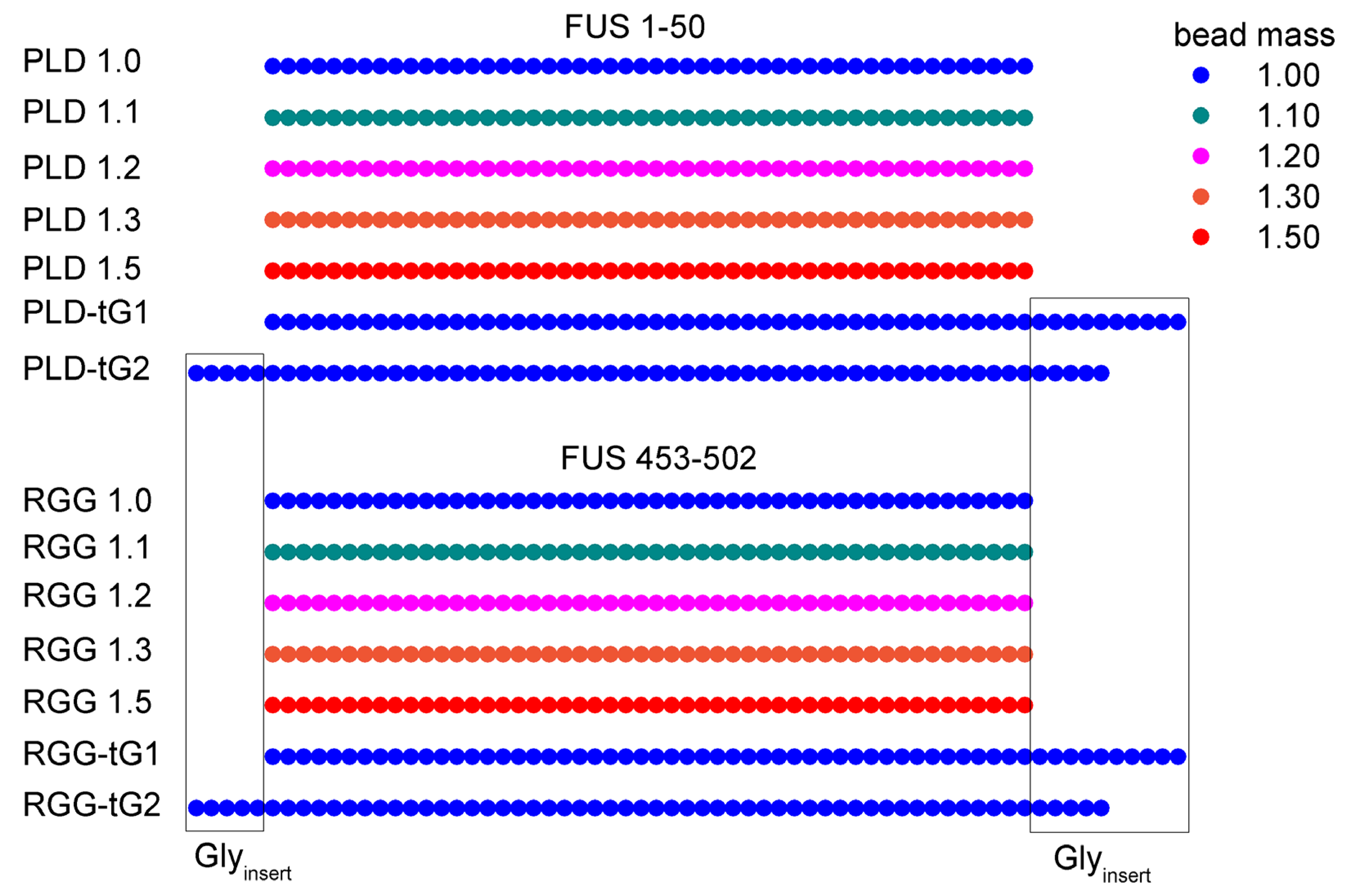
Figure 1. The schematic diagram of different FUS chain models. The different colors represent different bead masses. The beads within rectangle area represent inserted glycine residues.
Biomolecules 13 00625 g001
Figure 2. PH − PL of PLD-tG (A) and RGG-tG (B) in different solvents changes with temperature when ε-insert=0.00001 kJ/mol. The PH and PL values are calculated with the last 1000 τ simulation data as PH − PL of all the simulations reaches equilibrium after 3000 τ (see Figures S4–S7). The gray line is PH − PL = 0.07.
Biomolecules 13 00625 g002
Figure 3. PH − PL of PLD (A) and RGG (B) with bead mass 1.0 and 1.2 in different solvents changes with temperature. The PH and PL values are calculated with the last 1000 τ simulation data as PH − PL of all the simulations reaches equilibrium after 3000 τ (see Supplementary Materials). The gray line is PH − PL =0.07.
Biomolecules 13 00625 g003
Figure 4. Critical temperature (TCr) of LLPS changes with PLD system mass or RGG system mass.
Biomolecules 13 00625 g004
Figure 5. The z motion rate of PLD (A) and RGG (B) with bead mass 1.0 and 1.2 in different solvents changes with temperature; PH − PL of PLD (C) and RGG (D) with bead mass 1.0 and 1.2 in different solvents change with z motion rate. The z motion rates are calculated by averaging 200 chains in the box with the last 1000 τ simulation data. The gray line is PH − PL = 0.07.
Biomolecules 13 00625 g005
Figure 6. The flux on the boundary line. (A) The flux of PLD 1.0 and PLD 1.2 in different solvents changes with temperature. (B) The flux of RGG 1.0 and RGG 1.2 in different solvents changes with temperature. (C) PH − PL of PLD 1.0 and PLD 1.2 in different solvents change with flux. (D) PH − PL of RGG 1.0 and RGG 1.2 in different solvents change with flux. The fluxes are calculated by averaging the last 1000 τ simulation data, and the boundary line is |z| = 25 nm. The gray line is PH − PL = 0.07.
Biomolecules 13 00625 g006
Figure 7. The distribution of probability of PLD (A) and RGG (B) with bead mass 1.0 and 1.2 as a function of displacement |z|. Data without charges and at 10 mM salt concentration solvent are shown in the upper panels and the bottom panels, respectively. The probability is the average value of window along |z| during the last 1000 τ simulation data.
Biomolecules 13 00625 g007
Figure 8. Head-to-tail distance (D) of PLD (A) and RGG (B) chains with bead mass 1.0 and 1.2 as a function of temperature. The D value is calculated by the mean value of the 200 chains in the system during the last 1000 τ simulation data.
Biomolecules 13 00625 g008
Figure 9. Head-to-tail distance (D) of PLD and RGG as a function of displacement |z|. (A) The head-to-tail distance of PLD 1.0 with no charge interaction. (B) The head-to-tail distance of PLD 1.0 with 10 mM salt solvent. (C) The head-to-tail distance of PLD 1.2 with no charge interaction. (D) The head-to-tail distance of PLD 1.2 with 10 mM salt solvent. (E) The head-to-tail distance of RGG 1.0 with no charge interaction. (F) The head-to-tail distance of RGG 1.0 with 10 mM salt solvent. (G) The head-to-tail distance of RGG 1.2 with no charge interaction. (H) The head-to-tail distance of RGG 1.2 with 10 mM salt solvent. Mean D of the chains in each window along |z| and standard error (σ) values during the last 1000 τ simulation data are illustrated in this figure. Considering the effect of boundary, the data with displacement z higher than 1400 are not calculated.
Biomolecules 13 00625 g009
Figure 10. Mean number intra-chain (Eintra) of and inter-chain (Einter) electrostatic contacts of RGG 1.0 (A) and RGG 1.2 (B) as a function of |z|. Average and standard error values during the last 1000 τ simulation data are illustrated in this figure.
Biomolecules 13 00625 g010
Disclaimer/Publisher’s Note: The statements, opinions and data contained in all publications are solely those of the individual author(s) and contributor(s) and not of MDPI and/or the editor(s). MDPI and/or the editor(s) disclaim responsibility for any injury to people or property resulting from any ideas, methods, instructions or products referred to in the content.