
Submicron Topographically Patterned 3D Substrates Enhance Directional Axon Outgrowth of Dorsal Root Ganglia Cultured Ex Vivo

 ,
, 
 , and
, and 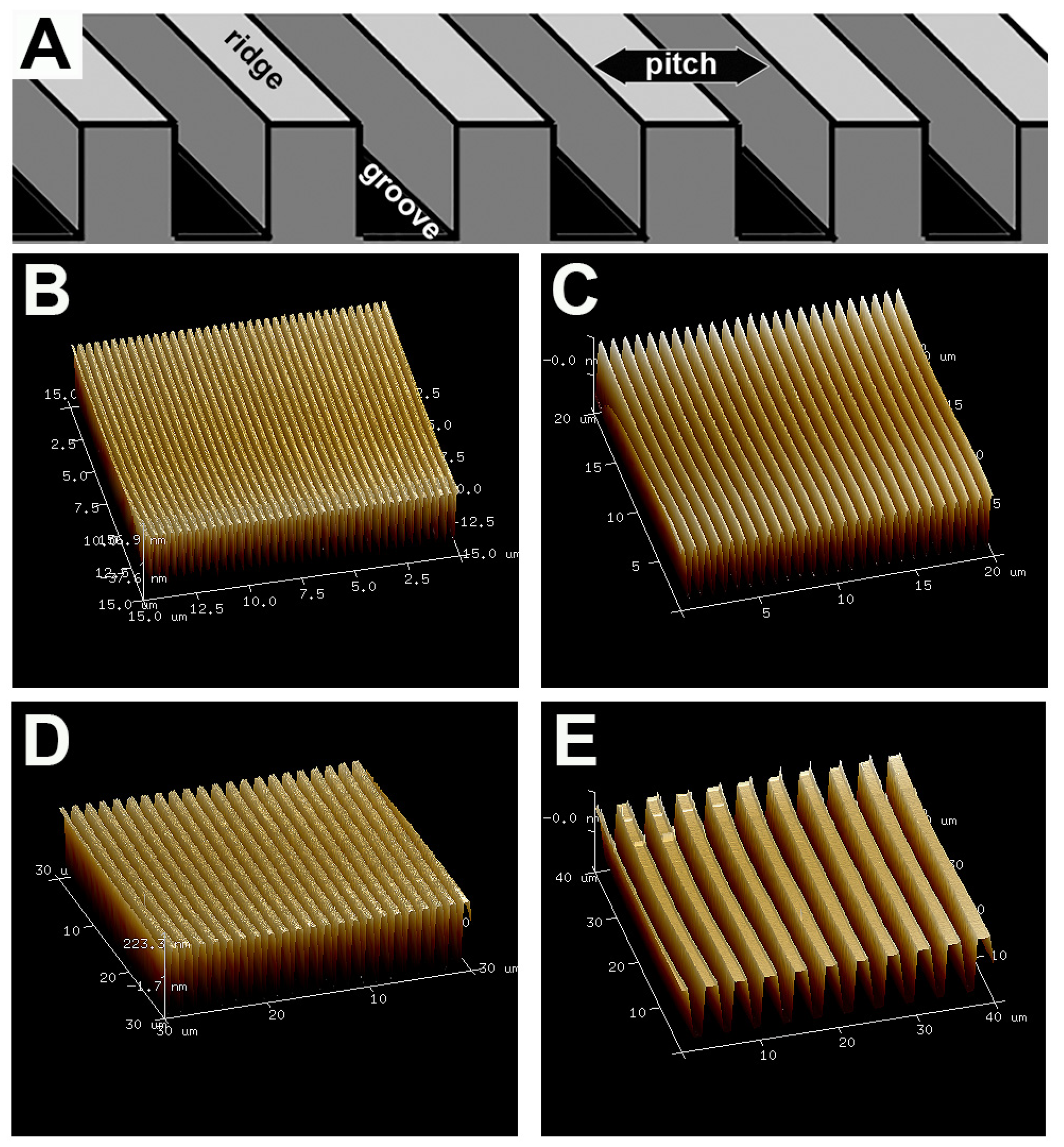
Abstract
1. Introduction
2. Materials and Methods
2.1. Fabrication of Topographic Surfaces
2.2. Preparation of Dorsal Root Ganglia (DRG) for Ex Vivo Growth
2.3. Immunofluorescence Labeling and Confocal Imaging
2.4. Image Analysis of Axonal Growth Parameters
2.5. Live Cell Imaging and Analysis
2.6. Fabrication of Half-Tube Structures
2.7. Imaging DRGs on Half-Tube Structures
2.8. Statistical Analysis
3. Results
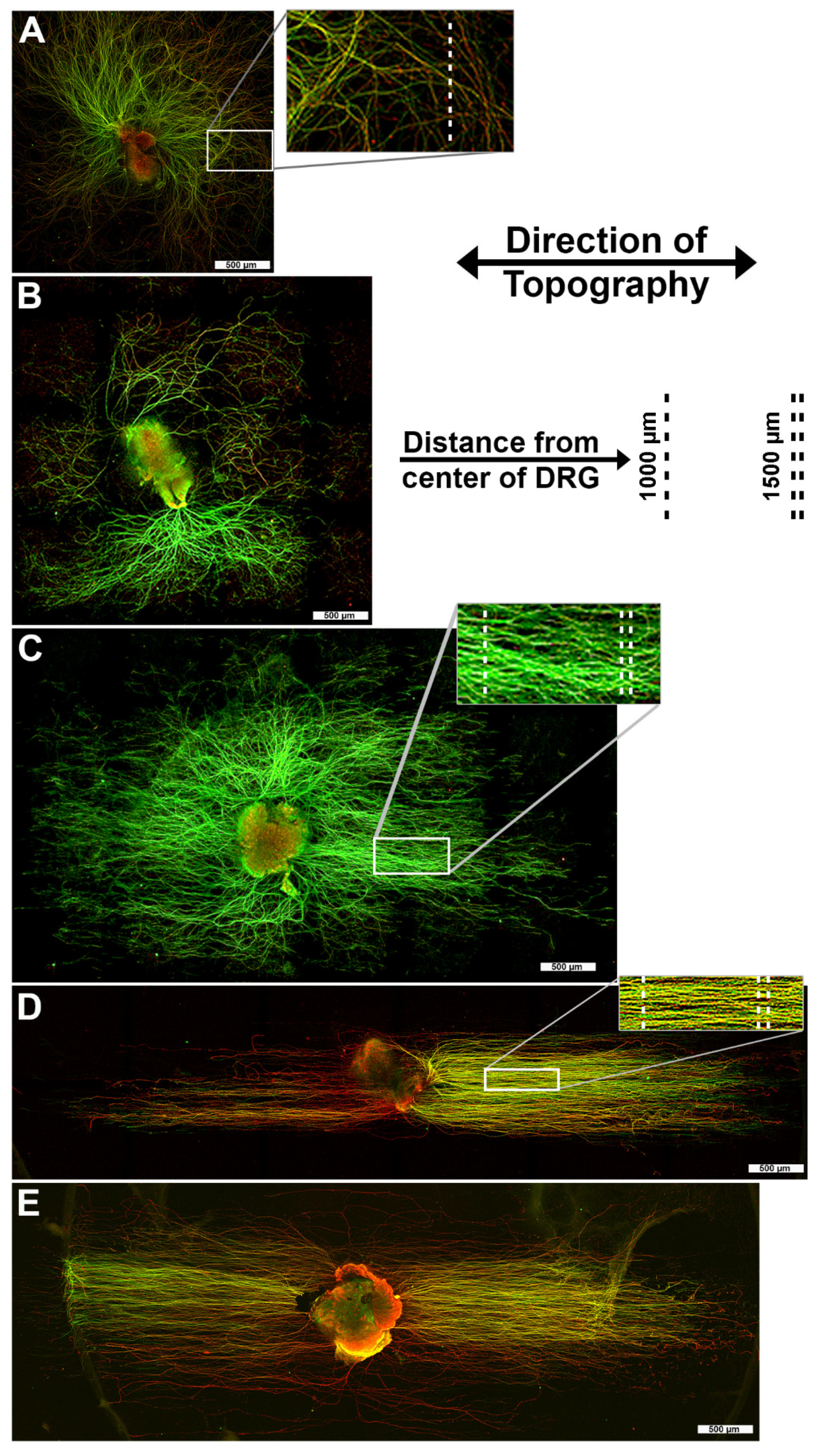
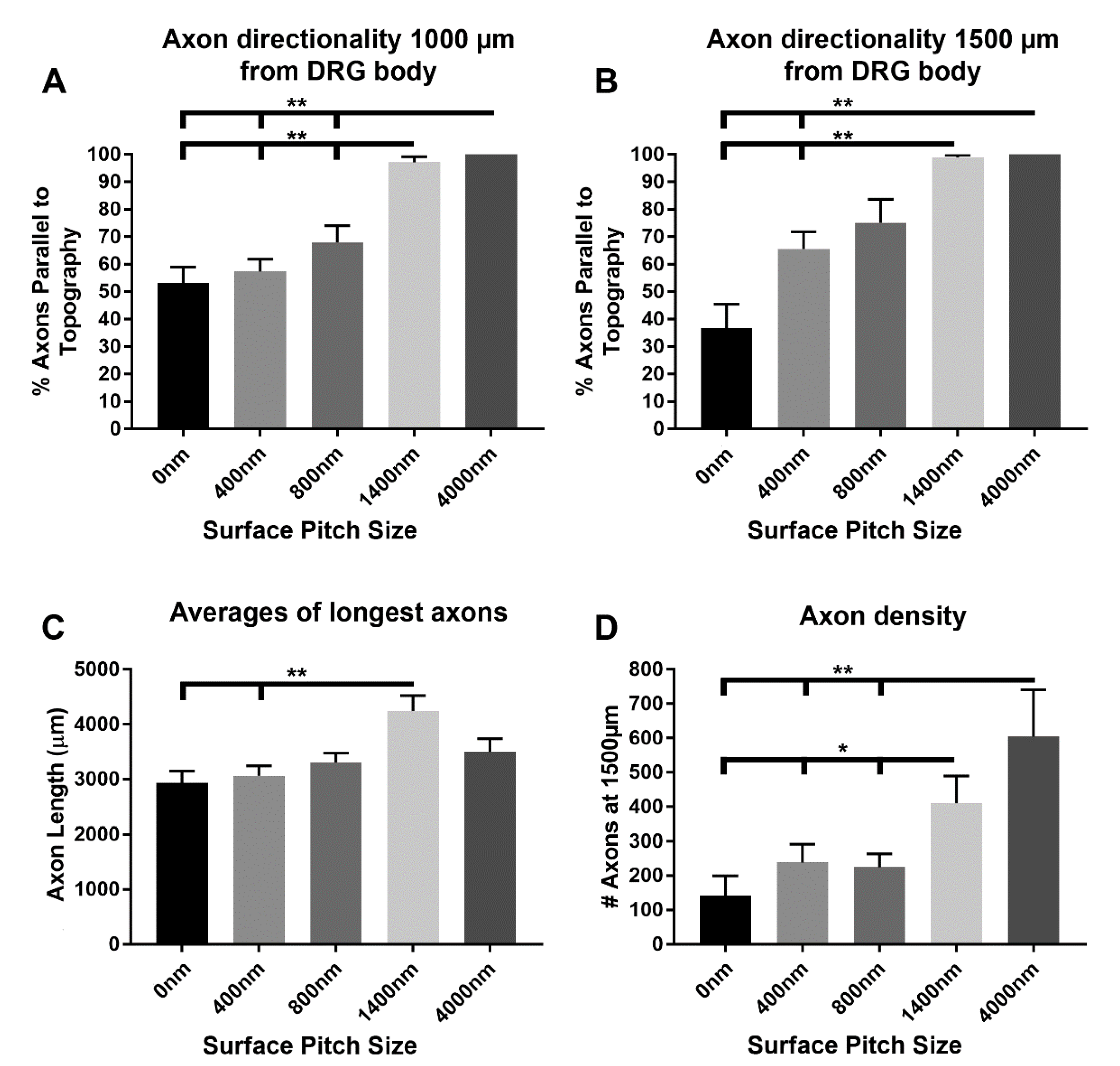
3.1. 1400 nm and 4000 nm Pitch Substrates Induce Directional Axon Regeneration from DRG Explants
3.2. 1400 nm and 4000 nm Pitch Sizes Influence Axon Length and Direction
3.3. 1400 nm and 4000 nm Pitch Sizes Resulted in Greater Distal Axonal Density Compared to Control and 400 nm Surfaces
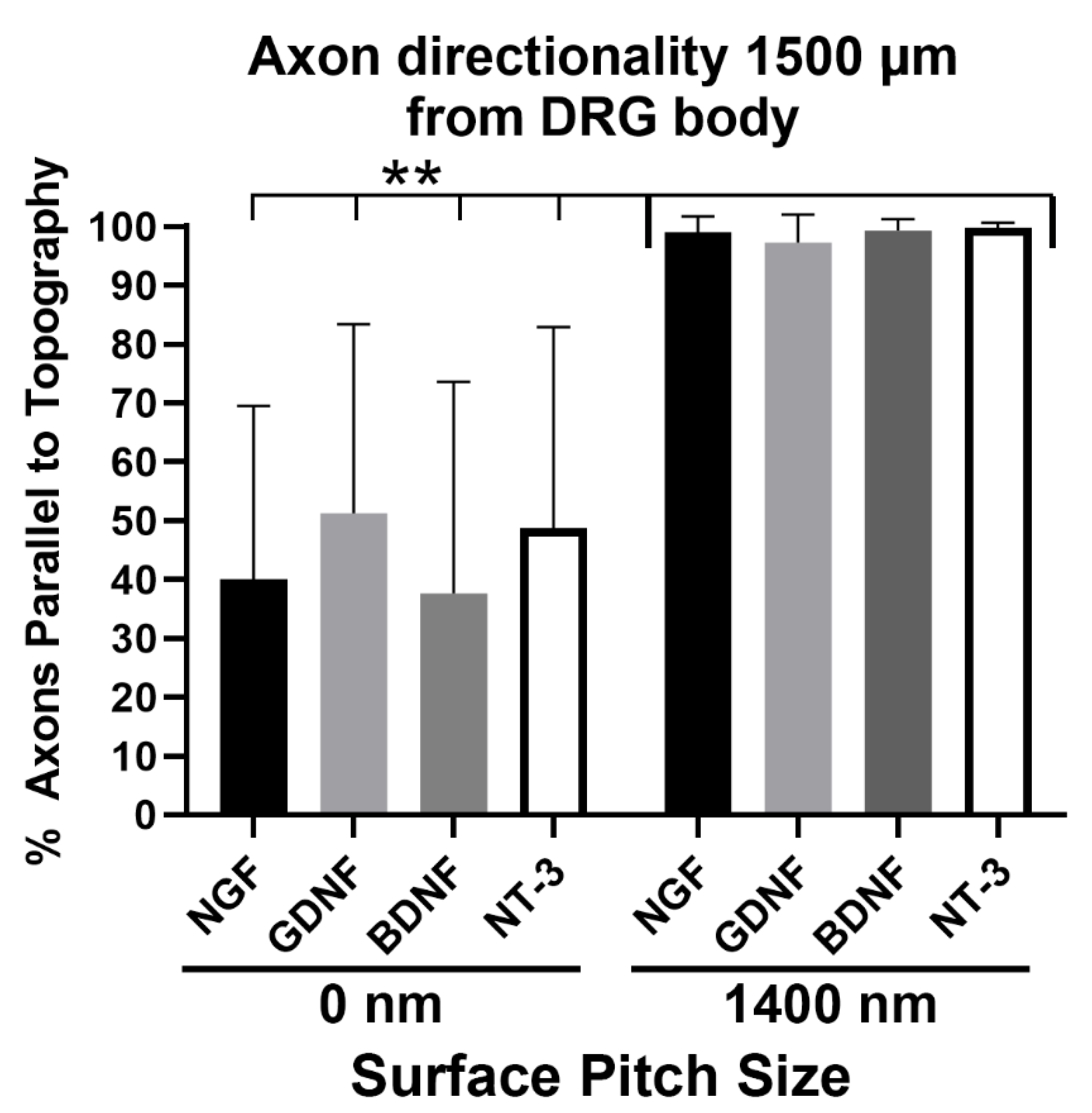
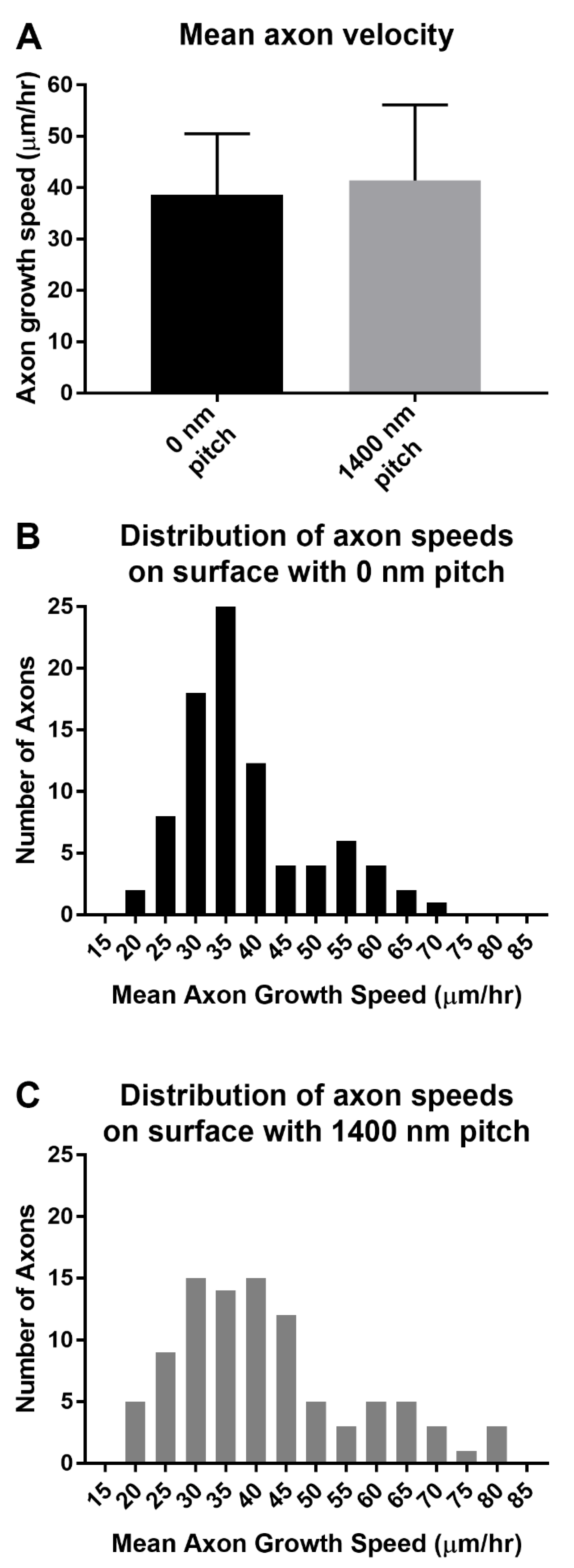
3.4. Axons Regenerating on 1400 nm Pitch Surface Maintained Parallel Directionality Irrespective of Neurotrophic Stimulus
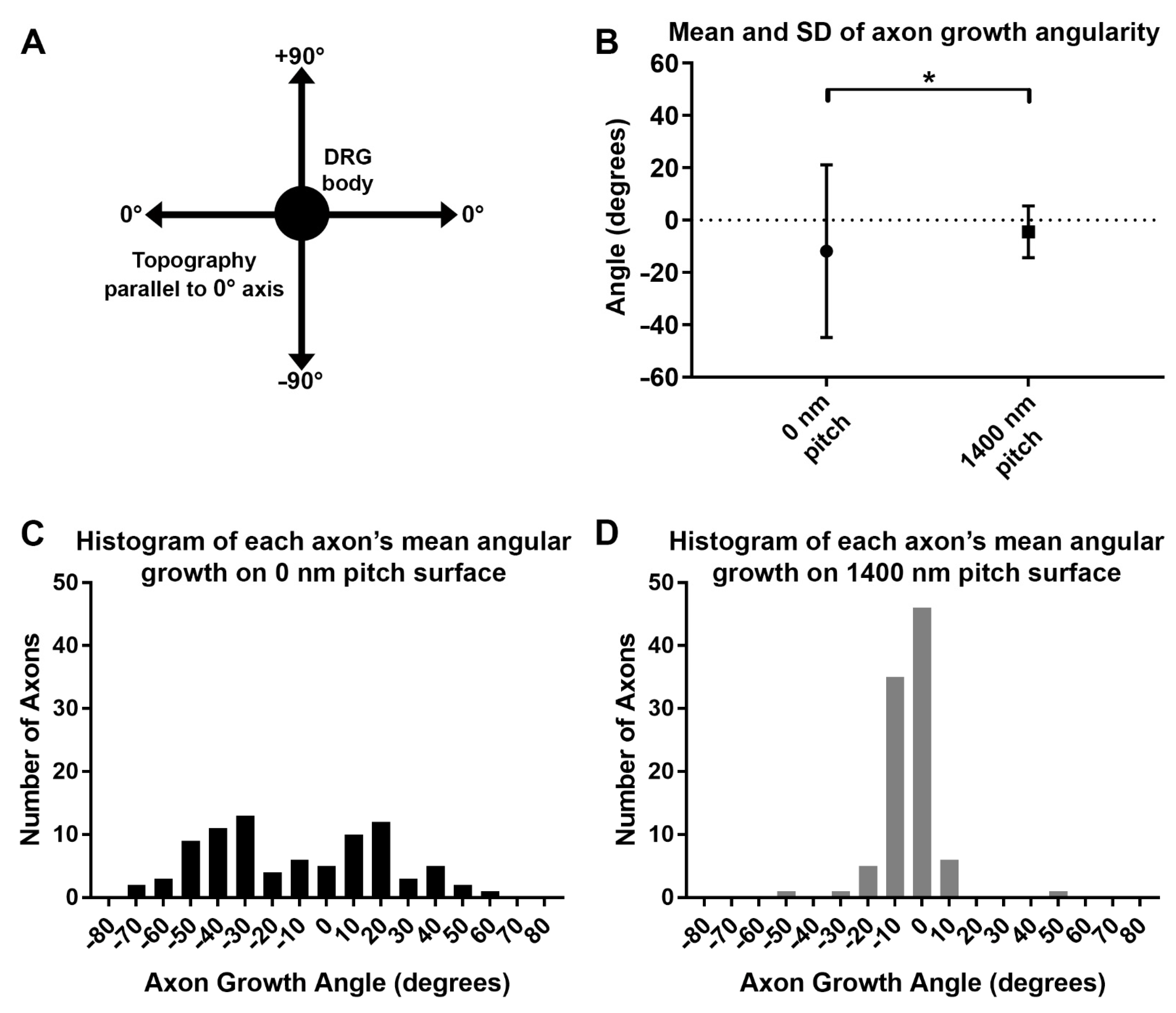
3.5. Axon Growth Angles Are Directed by Sub-Micron Sized Surface Features
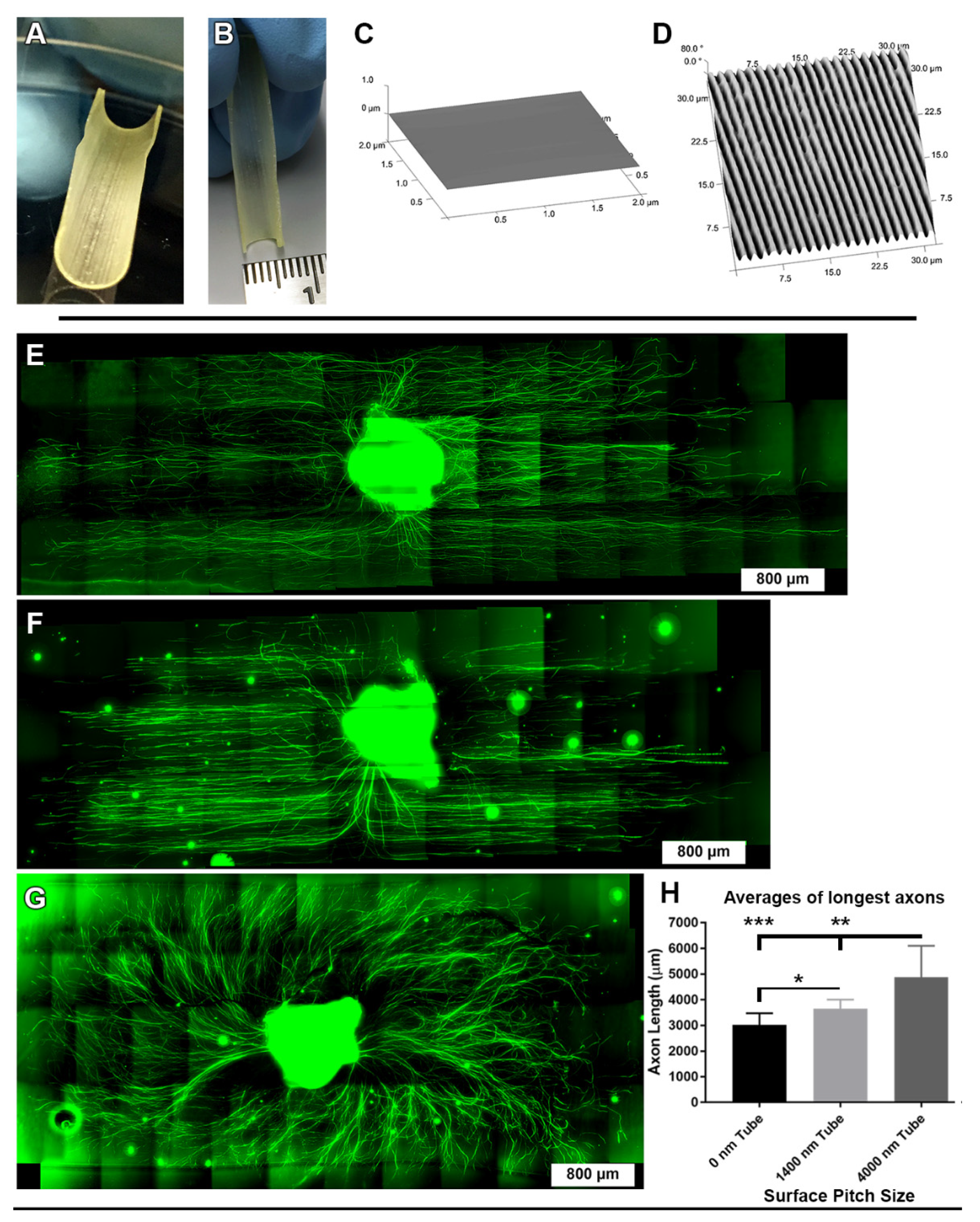
3.6. Directional DRG Explant Growth Was Similar on Topographically Patterned 3-Dimensional Tubes
4. Discussion
5. Conclusions
Supplementary Materials
Author Contributions
Funding
Institutional Review Board Statement
Informed Consent Statement
Data Availability Statement
Acknowledgments
Conflicts of Interest
References
- Pereira, J.A.; Lebrun-Julien, F.; Suter, U. Molecular mechanisms regulating myelination in the peripheral nervous system. Trends Neurosci. 2012, 35, 123–134. [Google Scholar] [CrossRef]
- Colognato, H.; Feltri, M.L. Human diseases reveal novel roles for neural laminins. Trends Neurosci. 2005, 28, 480–486. [Google Scholar] [CrossRef]
- Rosso, G.; Young, P.; Shahin, V. Implications of schwann cells biomechanics and mechanosensitivity for peripheral nervous system physiology and pathophysiology. Front. Mol. Neurosci. 2017, 10, 345. [Google Scholar] [CrossRef]
- Napoli, I.; Noon, L.A.; Ribeiro, S.; Kerai, A.P.; Parrinello, S.; Rosenberg, L.H.; Collins, M.J.; Harrisingh, M.C.; White, I.J.; Woodhoo, A.; et al. A central role for the ERK-signaling pathway in controlling Schwann cell plasticity and peripheral nerve regeneration in vivo. Neuron 2012, 73, 729–742. [Google Scholar] [CrossRef]
- Cattin, A.L.; Burden, J.J.; Van Emmenis, L.; Mackenzie, F.E.; Hoving, J.J.; Garcia Calavia, N.; Guo, Y.; McLaughlin, M.; Rosenberg, L.H.; Quereda, V.; et al. Macrophage-induced blood vessels guide schwann cell-mediated regeneration of peripheral nerves. Cell 2015, 162, 1127–1139. [Google Scholar] [CrossRef]
- Fornaro, M.; Marcus, D.; Rattin, J.; Goral, J. Dynamic environmental physical cues activate mechanosensitive responses in the repair schwann cell phenotype. Cells 2021, 10, 425. [Google Scholar] [CrossRef]
- Jessen, K.R.; Arthur-Farraj, P. Repair Schwann cell update: Adaptive reprogramming, EMT, and stemness in regenerating nerves. Glia 2019, 67, 421–437. [Google Scholar] [CrossRef]
- Spedden, E.; Wiens, M.R.; Demirel, M.C.; Staii, C. Effects of surface asymmetry on neuronal growth. PLoS ONE 2014, 9, e106709. [Google Scholar] [CrossRef]
- Xiong, Y.; Lee, A.C.; Suter, D.M.; Lee, G.U. Topography and nanomechanics of live neuronal growth cones analyzed by atomic force microscopy. Biophys. J. 2009, 96, 5060–5072. [Google Scholar] [CrossRef]
- Charron, F.; Tessier-Lavigne, M. Novel brain wiring functions for classical morphogens: A role as graded positional cues in axon guidance. Development 2005, 132, 2251–2262. [Google Scholar] [CrossRef] [PubMed]
- Dickson, B.J. Molecular mechanisms of axon guidance. Science 2002, 298, 1959–1964. [Google Scholar] [CrossRef] [PubMed]
- Dupont, S.; Morsut, L.; Aragona, M.; Enzo, E.; Giulitti, S.; Cordenonsi, M.; Zanconato, F.; Le Digabel, J.; Forcato, M.; Bicciato, S.; et al. Role of YAP/TAZ in mechanotransduction. Nature 2011, 474, 179–183. [Google Scholar] [CrossRef] [PubMed]
- Poitelon, Y.; Lopez-Anido, C.; Catignas, K.; Berti, C.; Palmisano, M.; Williamson, C.; Ameroso, D.; Abiko, K.; Hwang, Y.; Gregorieff, A.; et al. YAP and TAZ control peripheral myelination and the expression of laminin receptors in Schwann cells. Nat. Neurosci. 2016, 19, 879–887. [Google Scholar] [CrossRef]
- Evans, E.B.; Brady, S.W.; Tripathi, A.; Hoffman-Kim, D. Schwann cell durotaxis can be guided by physiologically relevant stiffness gradients. Biomater Res. 2018, 22, 14. [Google Scholar] [CrossRef] [PubMed]
- Miller, C.; Shanks, H.; Witt, A.; Rutkowski, G.; Mallapragada, S. Oriented Schwann cell growth on micropatterned biodegradable polymer substrates. Biomaterials 2001, 22, 1263–1269. [Google Scholar] [CrossRef]
- Nagata, I.; Nakatsuji, N. Rodent CNS neuroblasts exhibit both perpendicular and parallel contact guidance on the aligned parallel neurite bundle. Development 1991, 112, 581–590. [Google Scholar] [CrossRef]
- Weiss, P. The problem of specificity in growth and development. Yale J. Biol. Med. 1947, 19, 235–278. [Google Scholar]
- Niu, Y.; Stadler, F.J.; Fu, M. Biomimetic electrospun tubular PLLA/gelatin nanofiber scaffold promoting regeneration of sciatic nerve transection in SD rat. Mater. Sci Eng. C 2021, 121, 111858. [Google Scholar] [CrossRef]
- Xue, W.; Shi, W.; Kong, Y.; Kuss, M.; Duan, B. Anisotropic scaffolds for peripheral nerve and spinal cord regeneration. Bioact. Mater. 2021, 6, 4141–4160. [Google Scholar] [CrossRef] [PubMed]
- Escobar, A.; Reis, R.L.; Oliveira, J.M. Nanoparticles for neurotrophic factor delivery in nerve guidance conduits for peripheral nerve repair. Nanomedicine 2022, 17, 7. [Google Scholar] [CrossRef]
- Carvalho, C.R.; Costa, J.B.; Costa, L.; Silva-Correia, J.; Moay, Z.K.; Ng, K.W.; Reis, R.L.; Oliveira, J.M. Enhanced performance of chitosan/keratin membranes with potential application in peripheral nerve repair. Biomater. Sci. 2019, 7, 5451–5466. [Google Scholar] [CrossRef] [PubMed]
- Bugnicourt, G.; Brocard, J.; Nicolas, A.; Villard, C. Nanoscale surface topography reshapes neuronal growth in culture. Langmuir 2014, 30, 4441–4449. [Google Scholar] [CrossRef]
- Nectow, A.R.; Marra, K.G.; Kaplan, D.L. Biomaterials for the development of peripheral nerve guidance conduits. Tissue Eng. B Rev. 2012, 18, 40–50. [Google Scholar] [CrossRef] [PubMed]
- Li, W.; Tang, Q.Y.; Jadhav, A.D.; Narang, A.; Qian, W.X.; Shi, P.; Pang, S.W. Large-scale topographical screen for investigation of physical neural-guidance cues. Sci. Rep. 2015, 5, 8644. [Google Scholar] [CrossRef]
- Li, W.; Xu, Z.; Huang, J.; Lin, X.; Luo, R.; Chen, C.H.; Shi, P. NeuroArray: A universal interface for patterning and interrogating neural circuitry with single cell resolution. Sci. Rep. 2014, 4, 4784. [Google Scholar] [CrossRef]
- Shen, K.; Tsai, J.; Shi, P.; Kam, L.C. Self-aligned supported lipid bilayers for patterning the cell–substrate interface. J. Am. Chem. Soc. 2009, 131, 13204–13205. [Google Scholar] [CrossRef] [PubMed][Green Version]
- Tang, Q.Y.; Tong, W.Y.; Shi, J.; Shi, P.; Lam, Y.W.; Pang, S.W. Influence of engineered surface on cell directionality and motility. Biofabrication 2014, 6, 015011. [Google Scholar] [CrossRef] [PubMed]
- Hurtado, A.; Cregg, J.M.; Wang, H.B.; Wendell, D.F.; Oudega, M.; Gilbert, R.J.; McDonald, J.W. Robust CNS regeneration after complete spinal cord transection using aligned poly-L-lactic acid microfibers. Biomaterials 2011, 32, 6068–6079. [Google Scholar] [CrossRef] [PubMed]
- Wei, H.; Chen, Z.; Hu, Y.; Cao, W.; Ma, X.; Zhang, C.; Gao, X.; Qian, X.; Zhao, Y.; Chai, R. Topographically conductive butterfly wing substrates for directed spiral ganglion neuron growth. Small 2021, 17, e2102062. [Google Scholar] [CrossRef] [PubMed]
- Ghane, N.; Khalili, S.; Nouri Khorasani, S.; Esmaeely Neisiany, R.; Das, O.; Ramakrishna, S. Regeneration of the peripheral nerve via multifunctional electrospun scaffolds. J. Biomed. Mater. Res. A 2021, 109, 437–452. [Google Scholar] [CrossRef] [PubMed]
- Sunnerberg, J.P.; Descoteaux, M.; Kaplan, D.L.; Staii, C. Axonal growth on surfaces with periodic geometrical patterns. PLoS ONE 2021, 16, e0257659. [Google Scholar] [CrossRef] [PubMed]
- Tuft, B.W.; Li, S.; Xu, L.; Clarke, J.C.; White, S.P.; Guymon, B.A.; Perez, K.X.; Hansen, M.R.; Guymon, C.A. Photopolymerized microfeatures for directed spiral ganglion neurite and Schwann cell growth. Biomaterials 2013, 34, 42–54. [Google Scholar] [CrossRef]
- Berns, E.J.; Sur, S.; Pan, L.; Goldberger, J.E.; Suresh, S.; Zhang, S.; Kessler, J.A.; Stupp, S.I. Aligned neurite outgrowth and directed cell migration in self-assembled monodomain gels. Biomaterials 2014, 35, 185–195. [Google Scholar] [CrossRef] [PubMed]
- Goldner, J.S.; Bruder, J.M.; Li, G.; Gazzola, D.; Hoffman-Kim, D. Neurite bridging across micropatterned grooves. Biomaterials 2006, 27, 460–472. [Google Scholar] [CrossRef]
- Gaudin, R.; Knipfer, C.; Henningsen, A.; Smeets, R.; Heiland, M.; Hadlock, T. Approaches to peripheral nerve repair: Generations of biomaterial conduits yielding to replacing autologous nerve grafts in craniomaxillofacial surgery. Biomed Res. Int. 2016, 2016, 3856262. [Google Scholar] [CrossRef] [PubMed]
- Karuri, N.W.; Liliensiek, S.; Teixeira, A.I.; Abrams, G.; Campbell, S.; Nealey, P.F.; Murphy, C.J. Biological length scale topography enhances cell-substratum adhesion of human corneal epithelial cells. J. Cell Sci. 2004, 117, 3153–3164. [Google Scholar] [CrossRef]
- Liliensiek, S.J.; Campbell, S.; Nealey, P.F.; Murphy, C.J. The scale of substratum topographic features modulates proliferation of corneal epithelial cells and corneal fibroblasts. J. Biomed. Mater. Res. A 2006, 79, 185–192. [Google Scholar] [CrossRef]
- Liliensiek, S.J.; Wood, J.A.; Yong, J.; Auerbach, R.; Nealey, P.F.; Murphy, C.J. Modulation of human vascular endothelial cell behaviors by nanotopographic cues. Biomaterials 2010, 31, 5418–5426. [Google Scholar] [CrossRef]
- Fornaro, M.; Sharthiya, H.; Tiwari, V. Adult mouse DRG explant and dissociated cell models to investigate neuroplasticity and responses to environmental insults including viral infection. J. Vis. Exp. 2018, 133, e56757. [Google Scholar] [CrossRef]
- Preibisch, S.; Saalfeld, S.; Tomancak, P. Globally optimal stitching of tiled 3D microscopic image acquisitions. Bioinformatics 2009, 25, 1463–1465. [Google Scholar] [CrossRef]
- Meijering, E.; Dzyubachyk, O.; Smal, I. Methods for cell and particle tracking. Methods Enzymol. 2012, 504, 183–200. [Google Scholar] [CrossRef] [PubMed]
- Kirshner, H.; Aguet, F.; Sage, D.; Unser, M. 3-D PSF fitting for fluorescence microscopy: Implementation and localization application. J. Microsc. 2013, 249, 13–25. [Google Scholar] [CrossRef]
- Sage, D.; Donati, L.; Soulez, F.; Fortun, D.; Schmit, G.; Seitz, A.; Guiet, R.; Vonesch, C.; Unser, M. DeconvolutionLab2: An open-source software for deconvolution microscopy. Methods 2017, 115, 28–41. [Google Scholar] [CrossRef] [PubMed]
- Thevenaz, P.; Unser, M. User-friendly semiautomated assembly of accurate image mosaics in microscopy. Microsc. Res. Tech. 2007, 70, 135–146. [Google Scholar] [CrossRef]
- Noble, J.; Munro, C.A.; Prasad, V.S.; Midha, R. Analysis of upper and lower extremity peripheral nerve injuries in a population of patients with multiple injuries. J. Trauma 1998, 45, 116–122. [Google Scholar] [CrossRef] [PubMed]
- Moore, A.M.; Kasukurthi, R.; Magill, C.K.; Farhadi, H.F.; Borschel, G.H.; Mackinnon, S.E. Limitations of conduits in peripheral nerve repairs. Hand 2009, 4, 180–186. [Google Scholar] [CrossRef] [PubMed]
- Kim, Y.P.; Lee, G.S.; Kim, J.W.; Kim, M.S.; Ahn, H.S.; Lim, J.Y.; Kim, H.W.; Son, Y.J.; Knowles, J.C.; Hyun, J.K. Phosphate glass fibres promote neurite outgrowth and early regeneration in a peripheral nerve injury model. J. Tissue Eng. Regen. Med. 2015, 9, 236–246. [Google Scholar] [CrossRef]
- Liu, K.; Lu, Y.; Lee, J.K.; Samara, R.; Willenberg, R.; Sears-Kraxberger, I.; Tedeschi, A.; Park, K.K.; Jin, D.; Cai, B.; et al. PTEN deletion enhances the regenerative ability of adult corticospinal neurons. Nat. Neurosci. 2010, 13, 1075–1081. [Google Scholar] [CrossRef] [PubMed]
- Muratori, L.; Ronchi, G.; Raimondo, S.; Geuna, S.; Giacobini-Robecchi, M.G.; Fornaro, M. Generation of new neurons in dorsal root Ganglia in adult rats after peripheral nerve crush injury. Neural Plast. 2015, 2015, 860546. [Google Scholar] [CrossRef]
- Watanabe, I.S.; Semprini, M.; de-Moraes, S.R.; de-Souza, R.R. Diameter of axons in the lingual nerve of the mouse. A preliminary investigation. Braz. Dent. J. 1996, 7, 87–90. [Google Scholar]
- Shimozawa, A. Nerve fiber caliber analysis in the mouse intermediate nerve with electron microscope. Anat. Anz. 1982, 151, 286–296. [Google Scholar] [PubMed]
- Shimozawa, A.; Furuta, E. Nerve fiber caliber analysis in the mouse facial trunk distal to the stylomastoid foramen with the electron microscope. Anat. Anz. 1984, 157, 113–126. [Google Scholar] [PubMed]
- Siddiqui, A.M.; Brunner, R.; Harris, G.M.; Miller, A.L., 2nd; Waletzki, B.E.; Schmeichel, A.M.; Schwarzbauer, J.E.; Schwartz, J.; Yaszemski, M.J.; Windebank, A.J.; et al. Promoting Neuronal Outgrowth Using Ridged Scaffolds Coated with Extracellular Matrix Proteins. Biomedicines 2021, 9, 479. [Google Scholar] [CrossRef] [PubMed]
- Omidinia-Anarkoli, A.; Ephraim, J.W.; Rimal, R.; De Laporte, L. Hierarchical fibrous guiding cues at different scales influence linear neurite extension. Acta Biomater. 2020, 113, 350–359. [Google Scholar] [CrossRef]


Publisher’s Note: MDPI stays neutral with regard to jurisdictional claims in published maps and institutional affiliations. |
© 2022 by the authors. Licensee MDPI, Basel, Switzerland. This article is an open access article distributed under the terms and conditions of the Creative Commons Attribution (CC BY) license (https://creativecommons.org/licenses/by/4.0/).
Share and Cite
Fornaro, M.; Dipollina, C.; Giambalvo, D.; Garcia, R.; Sigerson, C.; Sharthiya, H.; Liu, C.; Nealey, P.F.; Kristjansdottir, K.; Gasiorowski, J.Z. Submicron Topographically Patterned 3D Substrates Enhance Directional Axon Outgrowth of Dorsal Root Ganglia Cultured Ex Vivo. Biomolecules 2022, 12, 1059. https://doi.org/10.3390/biom12081059
Fornaro M, Dipollina C, Giambalvo D, Garcia R, Sigerson C, Sharthiya H, Liu C, Nealey PF, Kristjansdottir K, Gasiorowski JZ. Submicron Topographically Patterned 3D Substrates Enhance Directional Axon Outgrowth of Dorsal Root Ganglia Cultured Ex Vivo. Biomolecules. 2022; 12(8):1059. https://doi.org/10.3390/biom12081059
Chicago/Turabian StyleFornaro, Michele, Christopher Dipollina, Darryl Giambalvo, Robert Garcia, Casey Sigerson, Harsh Sharthiya, Claire Liu, Paul F. Nealey, Kolbrun Kristjansdottir, and Joshua Z. Gasiorowski. 2022. "Submicron Topographically Patterned 3D Substrates Enhance Directional Axon Outgrowth of Dorsal Root Ganglia Cultured Ex Vivo" Biomolecules 12, no. 8: 1059. https://doi.org/10.3390/biom12081059
APA StyleFornaro, M., Dipollina, C., Giambalvo, D., Garcia, R., Sigerson, C., Sharthiya, H., Liu, C., Nealey, P. F., Kristjansdottir, K., & Gasiorowski, J. Z. (2022). Submicron Topographically Patterned 3D Substrates Enhance Directional Axon Outgrowth of Dorsal Root Ganglia Cultured Ex Vivo. Biomolecules, 12(8), 1059. https://doi.org/10.3390/biom12081059