Article

Long-Range Atom–Ion Rydberg Molecule: A Novel Molecular Binding Mechanism

Center for Integrated Quantum Science and Technology IQST, Institut für Quantenmaterie, Universität Ulm, 89069 Ulm, Germany
*
Author to whom correspondence should be addressed.
Atoms 2021, 9(2), 34; https://doi.org/10.3390/atoms9020034
Submission received: 4 May 2021 / Revised: 2 June 2021 / Accepted: 10 June 2021 / Published: 21 June 2021
(This article belongs to the Special Issue Low Energy Interactions between Ions and Ultracold Alkali Atoms)

Abstract

:
We present a novel binding mechanism where a neutral Rydberg atom and an atomic ion form a molecular bound state at a large internuclear distance. The binding mechanism is based on Stark shifts and level crossings that are induced in the Rydberg atom due to the electric field of the ion. At particular internuclear distances between the Rydberg atom and the ion, potential wells occur that can hold atom–ion molecular bound states. Apart from the binding mechanism, we describe important properties of the long-range atom–ion Rydberg molecule, such as its lifetime and decay paths, its vibrational and rotational structure, and its large dipole moment. Furthermore, we discuss methods of how to produce and detect it. The unusual properties of the long-range atom–ion Rydberg molecule give rise to interesting prospects for studies of wave packet dynamics in engineered potential energy landscapes.

1. Introduction

Molecules or bound complexes are often classified according to their binding mechanisms. The covalent bond, the ionic bond, the van der Waals bond, and the hydrogen bond are perhaps the ones that are most widely known, but they represent only a selection of all possible kinds of bonds. A recently discovered class of molecular bound states are long-range Rydberg molecules between two or more neutral atoms, where binding lengths can be in the micrometer range. After their prediction about two decades ago [1,2], several types of long-range Rydberg molecules have been experimentally observed in recent years [3,4,5,6,7,8] (for reviews, see, e.g., [9,10,11]).
In this work, we predict another species of the long-range Rydberg molecules. Here, a Rydberg atom is bound to an ion at a large given internuclear distance, which clearly exceeds the extension of the Rydberg electron wave function.
In a simple classical picture, the bound state is based on the electrostatic interaction between an induced electric dipole (the Rydberg atom) and a charge (the ion). Depending on the orientation of the electric dipole, the interaction can be attractive or repulsive. The electric field of the ion generally polarizes the neutral Rydberg atom according to its polarizability. This polarizability is a function of the electric field that the atom is exposed to and thus changes with the distance between the atom and the ion. The idea is now that a long-range Rydberg molecule can form at a distance where the polarizability flips its sign, such that at shorter distances, there is repulsion between the atom and the ion, and at larger distances, there is attraction.
The sign flip of the polarizability goes along with an avoided crossing between a low-field-seeking and a high-field-seeking energy level of the Rydberg atom, both of which experience individual Stark shifts in the electric field of the ion. For such an avoided crossing, the upper branch forms a potential well, which can exhibit molecular bound states. We note that a precondition for avoided crossings to occur is that the Rydberg atom exhibits a noninteger quantum defect [12]. For Rb, which we use for discussion in this work, the quantum defect and the avoided crossings are large. By contrast, for hydrogen, where no quantum defect is present, the crossings are not avoided. Curiously, it has been predicted that hydrogen interacting with a proton can form a different kind of long-range atom–ion Rydberg molecule; see, e.g., [13,14] and references therein.
For the long-range atom–ion Rydberg molecule predicted here, we show that a Rydberg series of bound states exists, within which the binding energies and bond lengths strongly vary. We discuss properties of the novel molecules, such as their stability and lifetime as well as their rotational and vibrational characteristics. Due to their large electric dipole moment, they can easily be aligned in a weak electric field. We propose controlled coupling of various quantum states via radio-frequency or microwave radiation. Finally, we describe how the predicted molecules can be created and detected in a cold atom experimental setup.
Before we start our investigation of the long-range atom–ion Rydberg bound states, we would like to mention that in recent years there has been a growing interest in the collisions and interactions of cold atoms and ions (for reviews, see, e.g., [15,16]). As of late, especially the interactions between ions and ultracold Rydberg atoms have been studied theoretically [17,18,19,20] as well as experimentally [21,22,23,24]. Building upon this, an observation of the proposed long-range atom–ion Rydberg molecule may be possible in the near future.

2. Binding Mechanism and Properties of the Long-Range Atom–Ion Rydberg Molecules

In the following, we explain in detail the binding mechanism of the long-range atom–ion molecule. It consists of a neutral Rydberg atom and an ion that are at a large enough internuclear distance r so that there is negligible overlap of the Rydberg electron orbital with the ion. We assume, for now, that the ionic core of the neutral atom is located at the origin. The ion is located on the z-axis at r = ( x = 0 , y = 0 , z = r ) . For simplicity, we consider the ion to be a point charge, with a single, positive elementary charge e. The ion generates a spherically symmetric electric field of strength E = e / ( 4 π ε 0 | r x | 2 ) at location x . Here, ε 0 is the vacuum permittivity. The electric field of the ion leads to level shifts and crossings in the atomic Rydberg atom, based on the Stark effect. The resulting level structures are quite similar to the well-known Stark maps of a Rydberg atom in a homogeneous electric field.
For the sake of a concrete example, we choose Rb as the neutral atom species. Figure 1 shows Rydberg levels of a Rb atom as a function of the internuclear distance r between atom and ion. Specifically, the level structures in the vicinity of n P states are considered. The principal quantum number is n = 17 for Figure 1a,b, while it is n = 47 for Figure 1c,d. In the given range of energies and internuclear distances, avoided level crossings between the high-field-seeking 17 P J ( 47 P J ) states and the low-field-seeking states of the hydrogenic manifold belonging to n = 14 ( n = 44 ) start to occur. Here, J denotes the total electronic angular momentum quantum number, which can be 1 / 2 or 3 / 2 for the P states. The avoided crossings give rise to potential wells within which molecular bound states can exist. Figure 1b,d are magnifications of the regions marked with magenta arrows in Figure 1a,c. The horizontal red lines in Figure 1b (Figure 1d) are the quantum-mechanical vibrational bound state levels in the wells (for rotational angular momentum l = 0 ).
The physics behind the bound states is as follows. The interaction is based on the interaction between an induced dipole moment and a charge. At the location of the bottom of a potential well, the dipole moment of the Rydberg atom flips its sign. At larger distances, it is a high-field seeker and thus is attracted by the ion. At shorter distances, it becomes a low-field seeker and is repelled by the ion. Hence, it oscillates about the bottom of the potential, the location of which corresponds to an approximate bond length.
To calculate the atomic Rydberg level energies in Figure 1, we use the Hamiltonian
H = H 0 + V I .
Here, H 0 represents the Hamiltonian of the unperturbed Rydberg atom, including the fine structure but ignoring the hyperfine structure. The eigenstates of H 0 are | n , S , L , J , m J , where L and S denote the quantum numbers of the electronic orbital angular momentum and the electronic spin, respectively. We obtain the corresponding eigenenergies E ( n , S , L , J , m J ) for the unperturbed atomic Rydberg states of Rb using the ARC (Alkali.ne Rydberg Calculator) package [25]. For the wave functions for the states | n , S , L , J , m J , we use analytical expressions from [26]. In Equation (1), the operator V I describes the electrostatic interaction between the Rydberg atom (treated as a Rydberg electron and a point-like Rydberg ionic core) and the ion. This potential energy is given by
V I = e 2 4 π ε 0 r e 2 4 π ε 0 | r r e | ,
where r e is the location of the Rydberg electron. It is possible to express V I in a multipole expansion (see, e.g., [27]), which yields
V I = e 2 4 π ε 0 l = 1 4 π 2 l + 1 r e l r l + 1 Y l 0 ( θ e , ϕ e ) .
Here, l is the order of the multipole term and Y l m represents the spherical harmonics. The quantum number m is m = 0 , due to rotational symmetry. Furthermore, the variables ( r e , θ e , ϕ e ) are the spherical coordinates for the Rydberg electron location
r e = r e sin ( θ e ) cos ( ϕ e ) sin ( θ e ) sin ( ϕ e ) cos ( θ e ) .
We note that in Equation (3), the zero order ( l = 0 ) multipole term drops out, as the corresponding contributions of Rydberg electron and Rydberg ionic core cancel each other. Thus, when the electron is located at the origin, i.e., r e = 0 , the interaction V I vanishes. Therefore, the atomic ground state will only be comparatively weakly affected by V I .
Restricting ourselves to a suitable Hilbert subspace { | n , S , L , J , m J } , we diagonalize the Hamiltonian H of the static (motionless) atom–ion system for a given, fixed internuclear distance r. For this, we calculate all matrix elements
H i j = ψ i | H | ψ j = ψ i | H 0 | ψ j + ψ i | V I | ψ j ,
where ψ j = | n , S , L , J , m J and ψ i = | n ˜ , S ˜ , L ˜ , J ˜ , m ˜ J represent the basis vectors. The diagonal elements H i i result from the first term in Equation (5) and are given by the energies E ( n , S , L , J , m J ) . The off-diagonal elements of H i j result from the second term in Equation (5) and arise from the interaction. By diagonalizing the matrix H i j , we obtain the energy levels for the perturbed Rb Rydberg atom. In our calculations, we only take into account multipole terms up to the order of l = 6 in Equation (3), since higher orders have negligible contributions. We note that truncating the multipole expansion of Equation (3) to the lowest order l = 1 would correspond to approximating the electric field to be homogeneous. Such a homogeneous field gives rise to the standard Stark maps [12].
In the spirit of the Born–Oppenheimer approximation, the obtained energy levels represent molecular potential energy curves V BO ( r ) of the atom–ion system. The relative motion of the atom–ion system in these potentials is described by
2 2 μ Δ + V BO ( r ) Ψ = E Ψ ,
which for χ / r = Ψ goes over into the radial Schrödinger equation
2 2 μ 2 r 2 + 2 l ( l + 1 ) 2 μ r 2 + V BO ( r ) χ = E χ .
The term
2 l ( l + 1 ) 2 μ r 2
is the centrifugal potential. Here, μ denotes the reduced mass of the diatomic molecule. Due to the rotational symmetry of V BO ( r ) , the angular momentum l for the molecular rotation is a good quantum number. The bound states of the Schrödinger equation correspond to the vibrational eigenstates of the atom–ion molecule with angular momentum l .
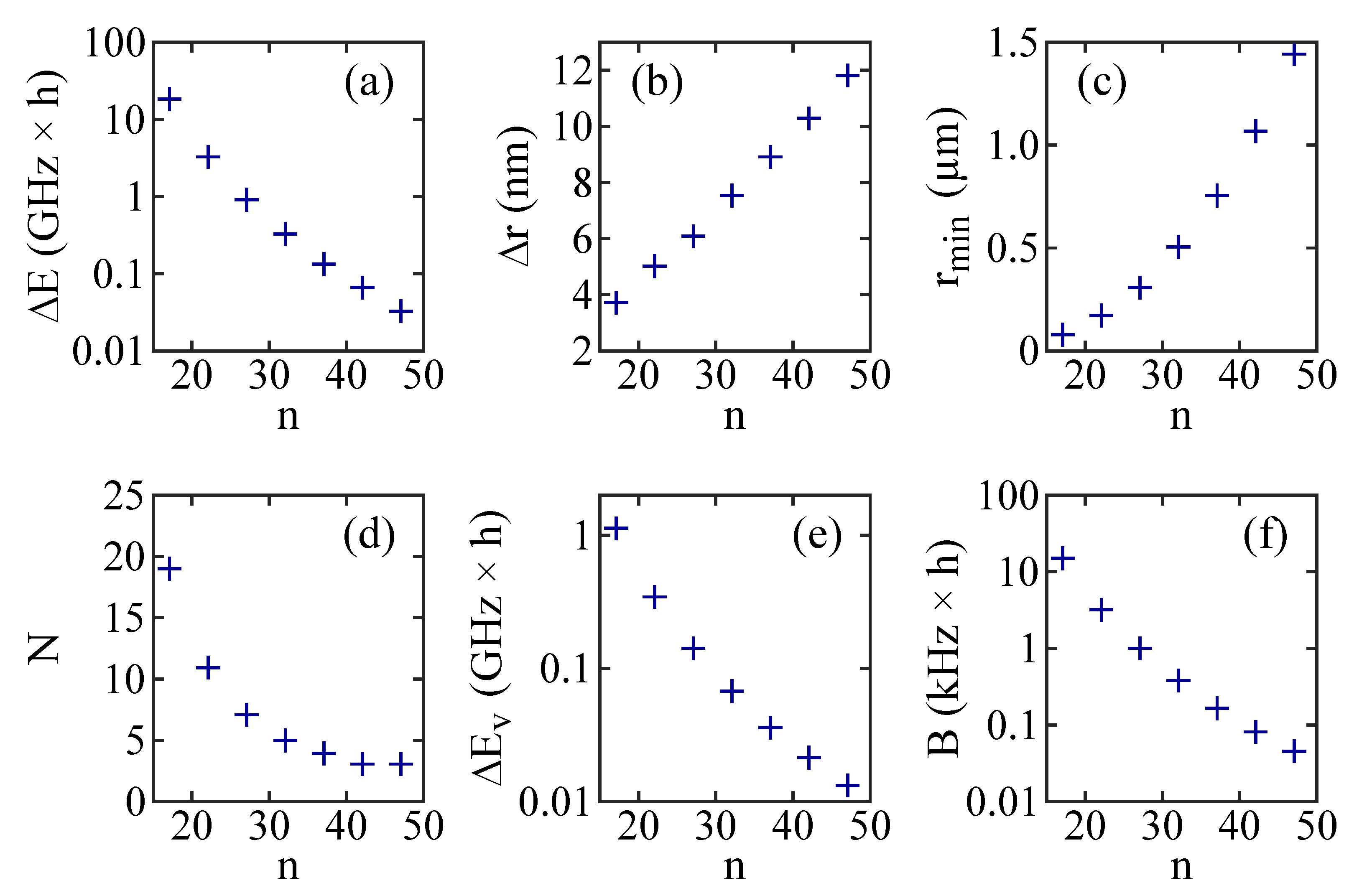
Bound state wells, similar to the ones discussed in Figure 1, also occur for different principal quantum numbers n. In fact, there exists a Rydberg series of potential wells for the long-range atom–ion Rydberg molecules. The well depth Δ E , the width Δ r at half the depth, and the position r min of the bottom of a well (see Figure 1b) change with n. Figure 2 shows these dependencies for the second outermost potential well associated with the n P 1 / 2 state, as n increases in steps of five units from n = 17 to n = 47 . As can be seen in Figure 2a, Δ E decreases by about three orders of magnitude from 18 GHz × h for n = 17 to about 30 MHz × h for n = 47 . At the same time, Δ r increases from about 4 nm to almost 12 nm (Figure 2b), and the binding length r min rises from 80 nm to a remarkable value of 1440 nm (Figure 2c).
As the potential wells change with n, so do the numbers of their vibrational bound states N and the vibrational splittings of the levels. This is shown in Figure 2d–f for the second outermost potential wells associated with the n P 1 / 2 states. The number of vibrational bound states N decreases from 19 to 3 as n increases from 17 to 47 (see Figure 2d). At the same time, the energy splitting for deeply bound vibrational levels drops from 1 GHz × h to 10 MHz × h (see Figure 2e). As the atom–ion interaction potential is spherically symmetric, it has rotational eigenstates. The rotational constant B can be estimated in the approximation of a rigid rotor using B = 2 / ( 2 μ r min 2 ) , where r min represents the binding length. Generally, B is quite small due to the long-range character of the dimer. For example, in Figure 2f we show the rotational constant for a 87 Rb atom bound to a 138 Ba + ion as a function of n for the given second outermost potential well. B decreases from 15 kHz × h for n = 17 to 50 Hz × h for n = 47 .
Finally, for completeness, we briefly consider hyperfine interaction, which is not included in our calculations. Hyperfine splittings of the 27 P 1 / 2 states of 87 Rb and 85 Rb are measured to be < 1 MHz × h [28]. The hyperfine splitting intervals scale as 1 / n eff 3 with the effective principal quantum number n eff , which is defined by n eff = n δ ( n ) using the quantum defect δ ( n ) . Therefore, for the investigated range of n from n = 17 to n = 47 the size of the hyperfine splitting will be orders of magnitude smaller than the typical depth of each molecular potential well and the vibrational level splitting (see Figure 1b,d). The rotational level structure, however, can show similar splittings as the hyperfine structure for specific ranges of rotational quantum numbers.

3. Stability and Lifetime of the Long-Range Atom–Ion Rydberg Molecules

One possible decay channel for a long-range atom–ion Rydberg molecule is radiative decay. The radiative lifetime of a molecular state will be generally similar to the one for the corresponding atomic Rydberg state. Considering decay due to spontaneous photon emission and assuming zero temperature, the lifetime τ of Rydberg atoms increases with n eff as n eff α [29,30,31], where α 3 for the alkali atoms. At finite temperature T, the total lifetime τ T can be obtained from 1 / τ T = 1 / τ + 1 / τ bb . Here, 1 / τ bb is the decay rate due to black-body radiation. We note that τ bb approximately follows the scaling law τ bb n 2 / T for large n. For example, the lifetimes of the 17 P 1 / 2 and 17 P 3 / 2 levels of 87 Rb are about 5 μ s ( 8 μ s ) at T = 350 K ( T = 0 K ) according to the calculation in [32], which includes the effects due to the core polarizability, spin–orbit interaction, and black-body radiation. A lifetime of 5 μ s corresponds to a natural linewidth of 200 kHz / ( 2 π ) . This is, by the way, already larger than B / h for the rotational constant of 15 kHz × h we calculated in the previous section. Therefore, low rotational levels within a vibrational state cannot be resolved.
Another possible decay channel is the tunneling of the molecule through the outer (or inner) potential barrier of a well. Let us consider the second outermost potential well associated with the 17 P 1 / 2 state, located at r min 80 nm (see Figure 1a,b). Here, the most weakly bound vibrational states may undergo tunneling towards larger internuclear distances. After passing the barrier, the molecule accelerates along the repulsive potential energy curve and dissociates. The transmission probability P t of a molecule impinging on a barrier can be estimated by
P t = exp 2 2 μ T p 1 T p 2 V ( r ) E m d r ,
where E m is the energy of the molecule. T p 1 and T p 2 are the classical turning points for the potential barrier V ( r ) . For the given well we obtain P t = 2.7 × 10 2 , P t = 5.9 × 10 4 , P t = 1.1 × 10 5 , and P t = 2.4 × 10 7 for the four energetically highest vibrational levels, respectively. As expected, there is a fast increase of P t with increasing vibrational quantum number close to the threshold of the barrier. A molecular decay rate γ t due to tunneling can be estimated by multiplying the tunneling probability with the frequency of the oscillatory motion, which is about 1 GHz . Therefore, γ t is on the order of a few 10 7 s 1 for the most weakly bound level. For tunneling out of the corresponding well associated with the 47 P 1 / 2 state (see Figure 1c,d), the calculation yields P t = 0.38 , P t = 3.3 × 10 3 , and P t = 4.8 × 10 5 for the three available vibrational states. The frequency of the oscillatory motion, however, is only about 10 MHz and, therefore, the decay rates γ t are still moderate.
In principle, a long-range atom–ion Rydberg molecule can also decay at the bottom of its potential well due to a nonadiabatic transition to another potential energy curve. Within the Landau–Zener theory [33,34] for avoided crossings, the probability for nonadiabatic transfer is given by
P LZ = exp π Ω 2 2 v a d E ( r ) d r ,
where Ω is the energy splitting at the crossing, v a is the velocity for the approach to the energy gap, and d E ( r ) d r is the differential slope of the two crossing potential energy curves. The rate for a nonadiabatic Landau–Zener transition is obtained by multiplying P LZ with the frequency of oscillatory motion. We have verified for the second outermost potential wells (for Rb, ranging from 17 P 1 / 2 to 47 P 1 / 2 ) that decay of the molecular states via this process is completely negligible as compared to radiative decay. For this, we used a maximal velocity v a corresponding to a kinetic energy equal to the potential well depth Δ E .
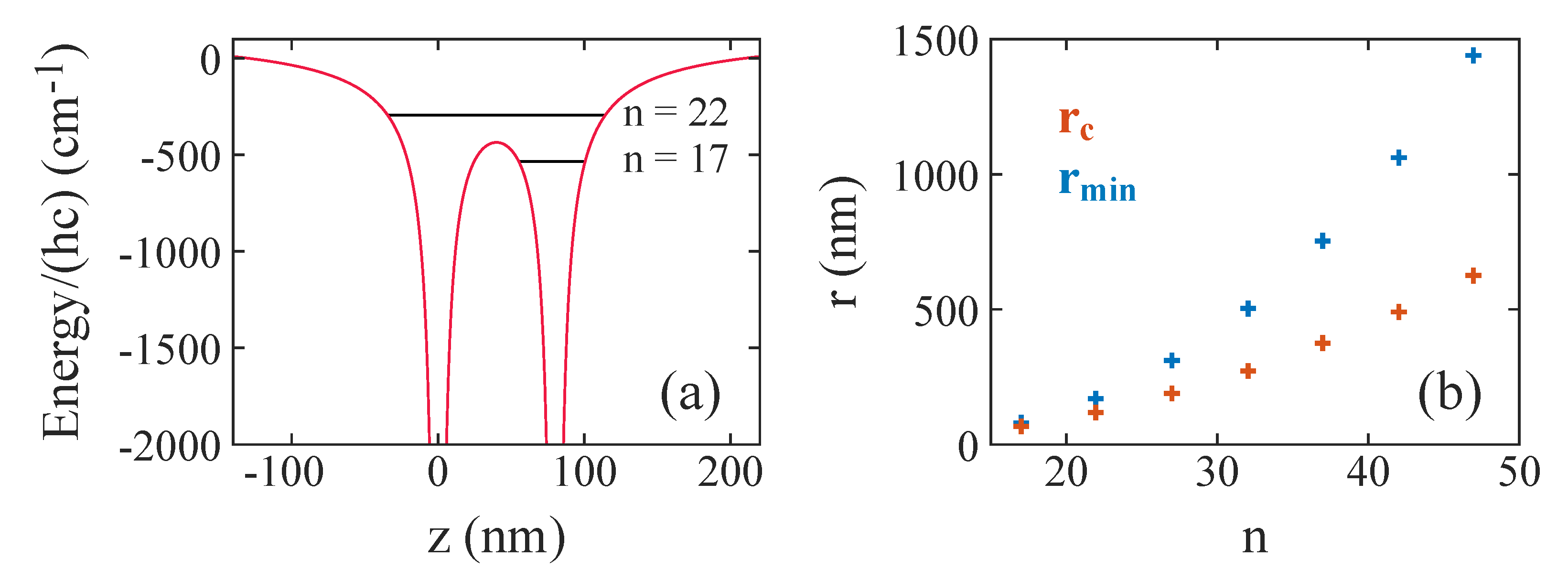
Finally, we discuss the stability of long-range atom–ion Rydberg molecules in terms of over-barrier motion [35]. In Figure 3a, the red solid lines show the total Coulomb potential of the Rydberg electron and the two ionic cores
V Cou = e 2 4 π ε 0 1 | z | 1 | r z | + 1 r ,
where all three particles are located on the z-axis. The electron is at position z, and the ionic cores are at positions z = 0 and z = 80 nm (such that their distance is r = 80 nm ). At half the distance between the cores, i.e., at z = 40 nm , a potential barrier for the electron occurs. Our type of long-range atom–ion Rydberg molecule cannot energetically exist above this potential barrier because the electron could freely pass from one ionic core to the other one, corresponding to a charge exchange between the atom and the ion. There still might be molecular bound states in this regime, but these are of a different type and we will not consider them any further here.
In the following, we roughly estimate at what internuclear distance over-barrier motion will set in if the initial atomic Rydberg state is a n P 1 / 2 state. For this, we simply compare the energy of an electron in an unperturbed atomic Rydberg level to the barrier height. The energy of an unperturbed Rydberg level is R y n eff 2 , where R y 13.605 eV is the Rydberg energy. For calculating the quantum defect δ ( n ) = δ 0 + δ 2 / ( n δ 0 ) 2 for n P 1 / 2 states of Rb we use the quantum defect parameters δ 0 = 2.6548849 ( 10 ) and δ 2 = 0.2900 ( 6 ) from [28]. The barrier energy at the top is 3 e 2 / ( π ε 0 r ) . Therefore, the critical distance below which over-barrier motion occurs is given by
r c = 3 e 2 4 π ε 0 R y ( n δ ( n ) ) 2 .
This is plotted in Figure 3b along with values r min for the locations of the second outermost potential wells associated with the n P 1 / 2 states. For large n, r c is significantly smaller than r min and, therefore, the potential barrier prevents charge exchange, protecting the long-range atom–ion Rydberg molecules. As n decreases, r c approaches r min . For the lowest n considered here, n = 17 , the calculation yields r c = 65 nm , which is already close to r min 80 nm (see also Figure 1a).
Even for energies slightly below the potential barrier charge exchange might occur due to tunneling of the electron through the barrier. This would lead again to a breakdown of our scheme. Therefore, we have calculated tunneling probabilities similarly as in Equation (9). For n = 17 and an approximate binding length of r min 80 nm , and using the unperturbed level energy of the Rydberg atom, we obtain a tunneling probability of about 3 × 10 12 . The frequency of the oscillatory motion of the Rydberg electron in a state characterized by n eff , 1 can be roughly estimated by the frequency separation of this state to the next neighboring, energetically lower state characterized by n eff , 2 n eff , 1 1 , i.e., R y ( n eff , 1 2 n eff , 2 2 ) h 1 . For n = 17 , the frequency of the oscillatory motion is about 2 × 10 12 Hz . Consequently, the tunneling rate is 6 s 1 , which is negligible as compared to the natural (radiative) decay rate of the molecule. For the states with n > 17 considered in Figure 3b and corresponding approximate binding lengths r min , the tunneling rates quickly decrease further with increasing n.

4. Production and Detection of the Long-Range Atom–Ion Rydberg Molecules

4.1. Production by Photoassociation

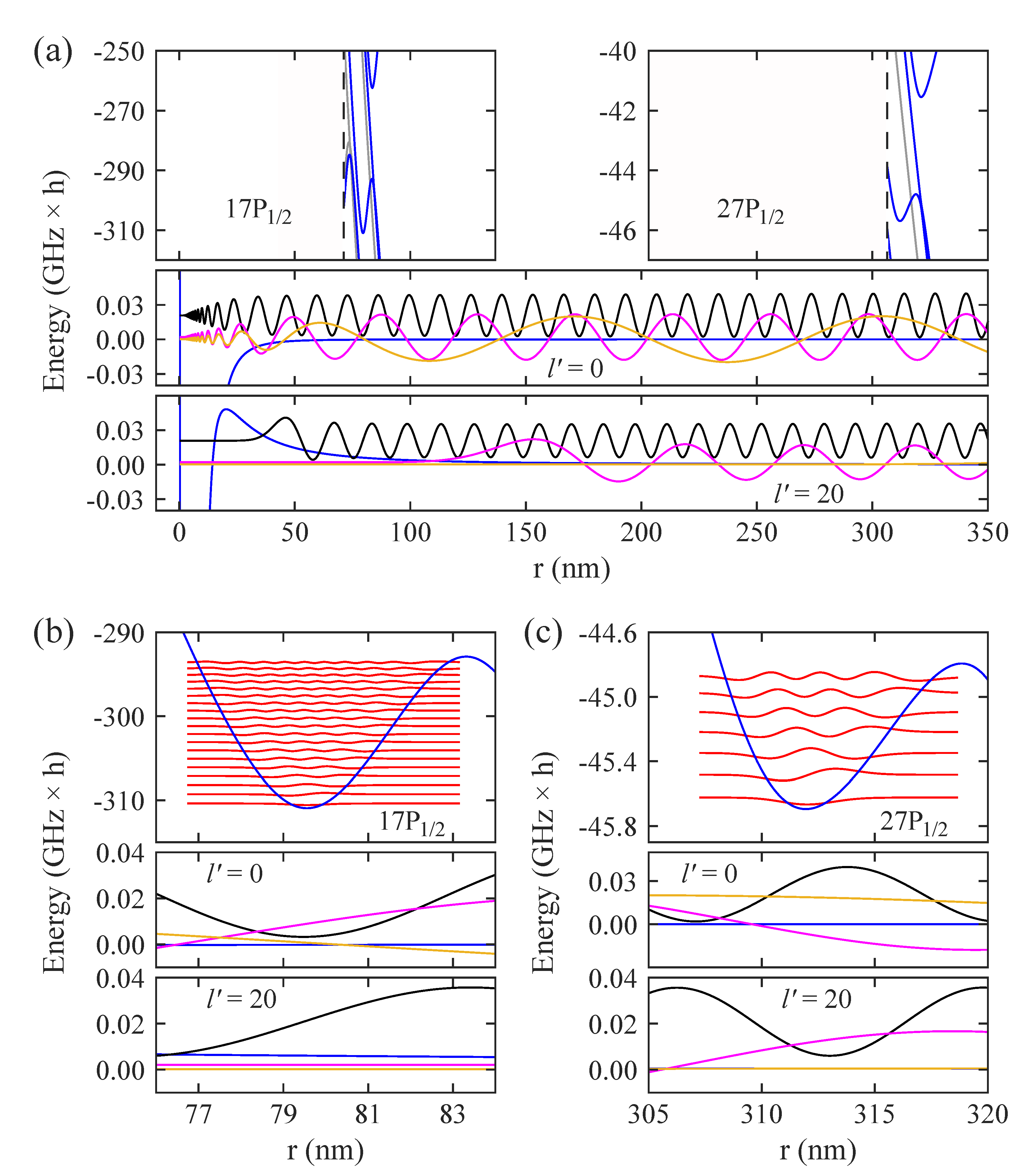
A possible way to create a long-range atom–ion Rydberg molecule is resonant photoassociation. For example, we consider a single ion immersed in a cloud of ultracold neutral Rb atoms in the ground state 5 S 1 / 2 . When a colliding atom–ion pair reaches the distance of the molecular bond length ( r min of a potential well), a laser with a wavelength of 300 nm can resonantly drive a transition to an atomic Rydberg state with sufficient P character. The partial wave will generally not change or only slightly change during photoassociation. Specifically, if the atom and the ion collide in a partial wave with angular momentum l , then the produced atom–ion molecule will typically have a rotational angular momentum of l or l ± 1 (see discussion further below). The binding lengths are quite large, ranging between 80 and 1440 nm in our examples. In particular, they are much larger than the typical internuclear distance where the maximum of the angular momentum barrier is located (see, e.g., the lower panel of Figure 4a). Therefore, even for relatively low collision energies of 1 mK × k B , where k B is Boltzmann’s constant, quite a number of partial waves can contribute to the photoassociation. The precise number of partial waves depends of course on the atomic mass of the involved particles and the photoassociation distance, in addition to the precise collision energy (cf. Equation (14) further below).
In Figure 4, various examples for different parameters for photoassociation are presented. Specifically, here, we consider a 5 S 1 / 2 electronic ground state 87 Rb atom colliding with a 138 Ba + ion in its electronic ground state 6 S 1 / 2 . For simplicity, the hyperfine structure of the Rb atom is ignored. Furthermore, in general, the total electronic spin degree of freedom is not taken into account, i.e., we do not discriminate between electronic singlet and triplet states. The blue solid lines in the middle and the lower panel of Figure 4a show the interaction potential for two different partial waves l = 0 (the s-wave) and l = 20 . Regarding l = 0 , we choose for the interaction potential at very short range ( r 4 nm ) the ( 1 ) 3 Σ + potential energy curve taken from [36]. The part at the longer range ( r 4 nm ) for l = 0 is given by the polarization potential 1 / r 4 (see, e.g., [15]). We have checked that these two parts are smoothly connected with each other. For l = 20 , the angular momentum potential of Equation (8), which gives rise to the centrifugal barrier, is added. The black, magenta, and ocher solid lines in the middle and the lower panel of Figure 4a are calculated scattering wave functions for collision energies E of ( 1 , 0.1 , 0.01 ) mK × k B , respectively. These are energy-normalized (cf. Equation (17) below). In order to carry out photoassociation, it is important that the scattering wave function and the wave function of the target molecular level have sufficient Franck–Condon overlap. We present in the upper panel of Figure 4a the potential energy curves in the regions of the two outermost molecular potential wells associated with the 17 P 1 / 2 (on the left) and 27 P 1 / 2 (on the right) states of Rb. Figure 4b,c are magnifications of these regions. Here, for simplicity, in the upper panels, we only show the second outermost potential wells together with the wave functions of the corresponding vibrational levels. A comparison to the scattering wave functions (middle and lower panels of Figure 4b,c) reveals that these can have decent overlap with atom–ion Rydberg molecule states, in general. We note, however, that the lower the collision energy, the smaller the number of partial waves that will contribute to the photoassociation. For example, this can be seen from the almost vanishing amplitude of the scattering wave function for the case E = 0.01 mK × k B and l = 20 over essentially the whole range of internuclear distances shown in Figure 4a.
Next, we provide a quantitative estimation for photoassociation. For low enough laser intensity, the occupation probability P m of an atom–ion molecular state is given by
P m = n at π v rel k 2 l = 0 l max ( 2 l + 1 ) γ s Δ 2 + ( γ + γ s ) 2 .
This result is extracted from [37], where an expression for the rate Γ = P m γ for excitation of the molecular state followed by its spontaneous decay is presented. Equation (13) is valid only for small values of P m . Here, n at is the particle density of the atomic cloud, v rel is the relative velocity between the collision partners, k = 2 μ E / 2 = μ v rel / is the wave number for reduced mass μ , and Δ is the detuning from resonance. The highest contributing partial wave is roughly determined by
l max 2 μ r min 2 E / .
In Equation (13), γ is the rate of natural spontaneous emission for the excited state, and γ s is the rate of stimulated decay back to the entrance channel. γ s can be expressed by
γ s = 2 π Ω R 2 2 | Ψ e | E , l | 2 ,
which involves the Franck–Condon overlap of the excited molecular bound state wave function Ψ e and the scattering wave function | E , l . Here, Ω R is the Rabi frequency for the optical coupling,
Ω R = E 0 | d ( r ) | = 2 I c ε 0 | d ( r ) | ,
where I is the intensity of the light, c is the speed of light, and d ( r ) is the dipole matrix element for the optical transition. In Equation (16), E 0 denotes the amplitude of the oscillating electric field of the light, which has a field strength of E 0 cos ( ω t ) . We note that the scattering wave function | E , l is energy-normalized so that for r it takes the form
r | E , l 2 μ π 2 k sin ( k r l π 2 + δ ˜ l ) ,
where δ ˜ l denotes the l -dependent scattering phase shift between the incoming and outgoing wave. This energy normalization assures that the given wave has an incoming particle flux that is independent of k.
The transition electric dipole moment d ( r ) varies with n, r, and the polarization of light (see, e.g., [17]). For simplicity, we consider here the transition electric dipole moment d for r , which neglects Stark level shifts and mixing of states due to the electric field of the ion, in principle. Regarding transitions with π -polarized light from ( 5 S 1 / 2 , m J = 1 / 2 ) toward ( n P 1 / 2 , m J = 1 / 2 ), generally ignoring the hyperfine structure, one obtains that | d | decreases from 5.5 × 10 3 e a 0 for n = 17 to 0.9 × 10 3 e a 0 for n = 47 , where a 0 = 0.529 × 10 10 m is the Bohr radius. According to [17], d ( r ) is on the order of d / 8 for such transitions, which should be a reasonable approximation for our purpose. To give an example, we now determine the occupation probability P m , as given in Equation (13), for vibrational levels within the second outermost potential well associated with the 27 P 1 / 2 state of Rb. For this state, a natural lifetime of τ = 1 / γ = 3.9 × 10 5 s and | d | / 8 = 0.3 × 10 3 e a 0 are calculated. We use an atomic density of n at = 1 × 10 12 cm 3 , which is low enough such that atom–atom–ion three-body recombination is negligible during the typical duration of the photoassociation experiment (see, e.g., [38]). Furthermore, an atom–ion collision energy of E = 1 mK × k B is considered. We assume that we resonantly address a molecular state with rotational angular momentum quantum number l res corresponding to Δ = 0 . All other possible transitions between scattering states and molecular rotational states for a given vibrational level are accounted for with their respective detunings Δ 0 . For a light intensity I = 1 kW cm 2 and l res = 100 we obtain from Equation (13) occupation probabilities P m in the range from 0.2 to 2% for the vibrational levels v = 0 to 6 in the well. Here, v is the vibrational quantum number. By increasing the laser intensity, the occupation probability P m still grows but, in general, not linearly anymore. We note that when choosing l res = 10 ( l res = 0 ) as compared to l res = 100 , P m is reduced typically by about a factor of 8 (a factor of 20 to 30) for a large part of the vibrational levels.
The vibrational levels on the potential wells should be spectroscopically resolvable when the collision energies of the atom–ion system are sufficiently low. For example, the energy level shift for a typical (thermally distributed) atom–ion collision energy of 1 mK × k B is about 21 MHz × h , which entails a corresponding inhomogeneous line broadening. Thus, according to Figure 2e, vibrational levels for the second outermost molecular potential wells associated with n P 1 / 2 Rb Rydberg states should be well resolvable for n 30 , as the vibrational level splitting is 100 MHz × h . The molecular rotation will not lead to significant additional broadening if the rotational angular momentum l does not change significantly in the photoassociation process. The maximal change in | Δ l | due to recoil from the ultraviolet photon with wavelength λ 300 nm in the Rydberg excitation can be estimated using | Δ l | = ( h / λ ) r min / h = r min / ( 300 nm ) . For n = 30 , the approximate binding length r min for molecules of the second outermost potential well is 400 nm , and hence, one obtains | Δ l | 1 . Furthermore, these parameters correspond to a rotational constant B of about 0.6 kHz × h when considering a 87 Rb 138 Ba + molecule. According to Equation (14), l max is 190 for this system, assuming a collision energy of E = 1 mK × k B . Consequently, about 190 partial waves can contribute to the photoassociation. The maximal energy shift (and line broadening) due to the change Δ l is then on the order of 2 B l max | Δ l | 2 MHz × h , which is small as compared to the vibrational splitting of about 100 MHz × h and as compared to the thermal broadening for collision energies on the order of 1 mK × k B .

4.2. Detection by Photoionization

In order to detect a long-range atom–ion Rydberg molecule, one can use photoionization. The resulting two positively charged ionic cores of the molecule repel each other such that the dimer gets dissociated. As a consequence, the total number of ionic particles increases, which can be observed with an ion detector. For heteronuclear long-range atom–ion Rydberg molecules, mass-resolved ion detection could even discriminate whether a detected ion originated from the involved Rydberg atom.
The efficiency of the detection scheme is directly related to the photoionization rate Γ PI = σ PI I λ PI / ( h c ) . Here, σ PI represents the photoionization cross-section and λ PI is the wavelength of the photoionizing light. As an example, we consider the wavelength of λ PI = 1064 nm for which high-power laser sources are available. According to [39], the photoionization cross-section σ PI for direct photoionization starting from Rb Rydberg P states ranges from about 1 × 10 21 cm 2 for n = 90 to about 2 × 10 19 cm 2 for n = 20 . Consequently, when addressing, e.g., the 17 P state of Rb, a laser intensity on the order of 10 5 W cm 2 is needed to obtain a photoionization rate comparable to the rate for natural radiative decay. Generally, the cross-section approximately scales as n 3 . Since, however, the lifetime of the molecule increases approximately as n eff 3 , there is only a comparatively small change of the ionization efficiency as a function of n for a given laser intensity.
Additional information can be drawn from the photoionization detection if it is combined with an energy spectroscopy of the released ions. Upon dissociation of the molecule, each of the ionic fragments gains a characteristic kinetic energy determined by the electrostatic potential energy E pot e 2 / ( 4 π ε 0 r min ) , where r min is roughly the binding length of the initial molecule. For r min 80 nm , as given for the potential wells involving 17 P states considered in Figure 1b, one obtains a total kinetic energy of about 200 K × k B (corresponding to 17 meV ), which is distributed over the two ionic fragments according to their mass ratio. Therefore, energy spectroscopy of product ions could reveal information about the binding length of the initial long-range atom–ion Rydberg molecules. Such energy spectroscopy may be carried out, e.g., by employing an ion trap [40] or by making use of time-of-flight techniques [41,42,43].

5. Prospects for Experiments with Long-Range Atom–Ion Rydberg Molecules

The long-range atom–ion Rydberg molecules possess several unusual properties that make them appealing for future investigations and applications. For example, they exhibit a very large electric dipole moment. Here, two contributions have to be considered. The first contribution comes about due to the fact that the charge of the ion is not located at the barycenter of the molecule, which gives rise to a permanent electric dipole moment even for the homonuclear case. The second contribution is represented by the induced electric dipole moment within the Rydberg atom as a consequence of the polarization in the electric field of the ion. Considering, e.g., a homonuclear dimer with an approximate binding length of r min 80 nm (see also Figure 1b), the first contribution to the electric dipole moment is approximately e r min / 2 6.4 × 10 27 Cm 1900 D . The induced electric dipole moment is comparatively small since molecular potential wells precisely occur at internuclear distances where the polarizability of the Rydberg atom changes its sign. Our calculations show that for all vibrational levels of the second outermost potential well associated with the 17 P 1 / 2 state of Rb, the induced electric dipole moment is below 20 D .
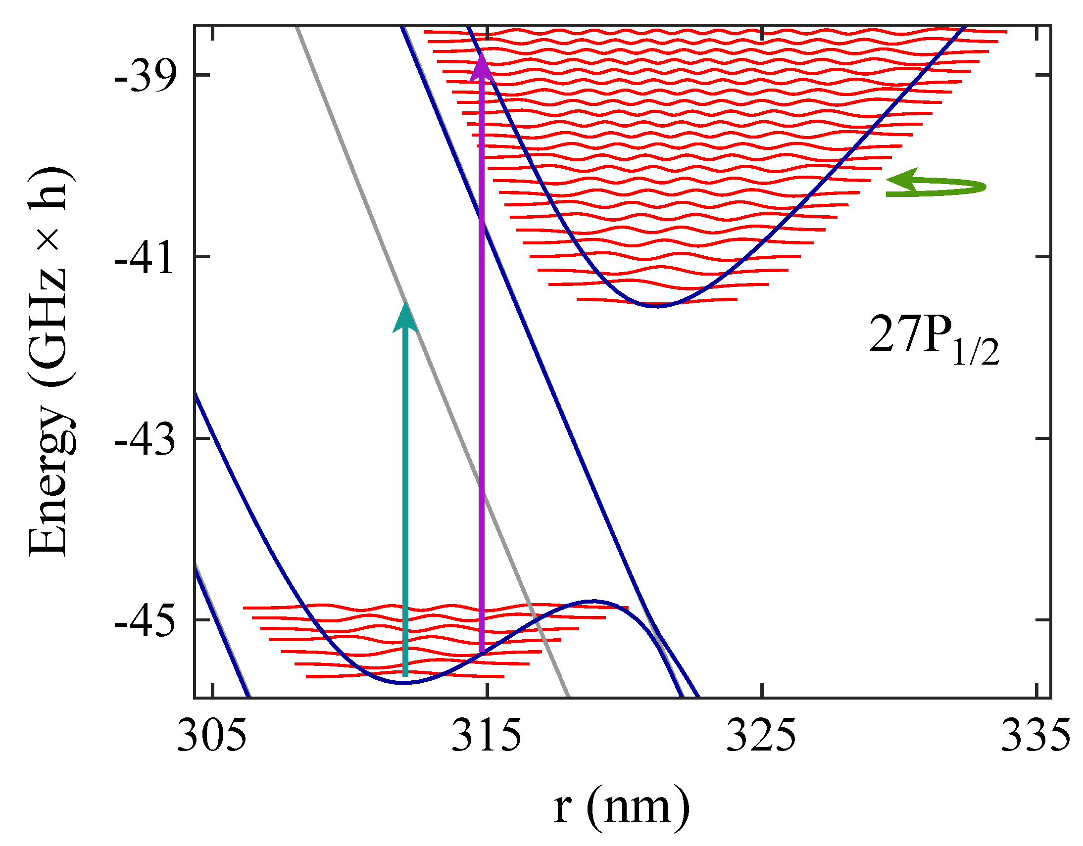
Since the rotational constants are very small, already small external electric fields on the V / m scale or below will be sufficient to align long-range atom–ion Rydberg molecules and to perform related experiments with them. Furthermore, their vibrational oscillation frequencies are in the 10 MHz to 1 GHz regime for the range of states considered here (cf. Figure 2e). The corresponding timescale of 1 to 100 ns is convenient for the investigation of wave packet dynamics, since it is largely accessible using standard lab electronics and laser switches. Microwave and radio-frequency radiation can be employed to drive transitions between vibrational and rotational states (see Figure 5 for different examples). This gives rise to interesting opportunities for coupling various neighboring potential wells in order to form novel, complex potential landscapes. The wave packet dynamics in such potential landscapes, which might involve tunneling and nonadiabatic transitions between states, can then be studied in detail. Related methods for potential engineering using, e.g., magnetic or electric fields are currently developed for (neutral) long-range Rydberg molecules [44,45].

6. Conclusions and Outlook

We have predicted a novel molecular binding mechanism between an atomic ion and a neutral Rydberg atom. The electric field of the ion induces Stark shifts and level crossings in the Rydberg atom, which gives rise to potential wells for long-range atom–ion Rydberg molecules. These molecules can possess extremely large binding lengths on the micrometer scale and correspondingly large, permanent electric dipole moments in the kilo-Debye range. From our investigation, we expect the stability and lifetime to be sufficient for detection and further applications. We have characterized the properties of the molecule as a function of the principal quantum number of the involved Rydberg atom, also regarding the vibrational and rotational level structure. In addition, we have proposed methods for production and detection of the long-range atom–ion Rydberg molecule and discussed prospects for studies of wave packet dynamics and potential landscape engineering.
One possible platform for the observation of the long-range atom–ion Rydberg molecule is based on hybrid atom–ion experiments. In these experiments, either laser-cooled and trapped ions are immersed into ultracold trapped clouds of neutral atoms, or ions are directly produced within an ultracold parent gas (for reviews, see, e.g., [15,16]). Typical setups allow for a high level of control over the collision energy between the atom and the ion, for which values around 1 mK × k B and below have been achieved [46,47,48,49]. We note that in Paul traps, electric fields are used to confine ions. These are, however, comparatively small. Typically, the electric field strength, even at a distance of a few μ m away from the trap center, is well below 100 V / m . Binding lengths in the range from 1.0 to 0.1 μ m for a long-range atom–ion Rydberg molecule already correspond to ion electric fields at the position of the neutral atom in the range from 1.44 to 144 kV / m . Therefore, the additional external electric field due to the ion trap only leads to a small distortion of the relevant molecular potential wells. Considering the current status of the field of hybrid atom–ion experiments, we anticipate that an observation of the long-range atom–ion Rydberg molecule proposed here is well within reach.
During the preparation of the manuscript, we became aware of work that is parallel to ours [50].

Author Contributions

J.H.D. and M.D. developed the concepts. S.H. carried out calculations of Stark maps, scattering wave functions and occupation probabilities. M.D. and J.H.D. wrote the manuscript. J.H.D. supervized the project. All authors have read and agreed to the published version of the manuscript.

Funding

This research was funded by the German Research Foundation (DFG) within the priority program “Giant Interactions in Rydberg Systems” (DFG SPP 1929 GiRyd).

Acknowledgments

We thank Dominik Dorer for comments, and Guido Pupillo, Nóra Sándor, and Georg Raithel for discussions on collisions between a Rydberg atom and an ion.

Conflicts of Interest

The authors declare no conflict of interest.

References

  1. Greene, C.H.; Dickinson, A.S.; Sadeghpour, H.R. Creation of polar and nonpolar ultra-long-range Rydberg molecules. Phys. Rev. Lett. 2000, 85, 2458–2461. [Google Scholar] [CrossRef] [PubMed]
  2. Boisseau, C.; Simbotin, I.; Côté, R. Macrodimers: Ultralong range Rydberg molecules. Phys. Rev. Lett. 2002, 88, 133004. [Google Scholar] [CrossRef] [Green Version]
  3. Bendkowsky, V.; Butscher, B.; Nipper, J.; Shaffer, J.P.; Löw, R.; Pfau, T. Observation of ultralong-range Rydberg molecules. Nature 2009, 458, 1005–1008. [Google Scholar] [CrossRef] [PubMed]
  4. Booth, D.; Rittenhouse, S.T.; Yang, J.; Sadeghpour, H.R.; Shaffer, J.P. Production of trilobite Rydberg molecule dimers with kilo-Debye permanent electric dipole moments. Science 2015, 348, 99–102. [Google Scholar] [CrossRef] [Green Version]
  5. Niederprüm, T.; Thomas, O.; Eichert, T.; Lippe, C.; Pérez-Ríos, J.; Greene, C.H.; Ott, H. Observation of pendular butterfly Rydberg molecules. Nat. Commun. 2016, 7, 12820. [Google Scholar] [CrossRef] [PubMed]
  6. Overstreet, K.R.; Schwettmann, A.; Tallant, J.; Booth, D.; Shaffer, J.P. Observation of electric-field-induced Cs Rydberg atom macrodimers. Nat. Phys. 2009, 5, 581–585. [Google Scholar] [CrossRef]
  7. Saßmannshausen, H.; Deiglmayr, J. Observation of Rydberg-atom macrodimers: Micrometer-sized diatomic molecules. Phys. Rev. Lett. 2016, 117, 083401. [Google Scholar] [CrossRef] [Green Version]
  8. Hollerith, S.; Zeiher, J.; Rui, J.; Rubio-Abadal, A.; Walther, V.; Pohl, T.; Stamper-Kurn, D.M.; Bloch, I.; Gross, C. Quantum gas microscopy of Rydberg macrodimers. Science 2019, 364, 664–667. [Google Scholar] [CrossRef] [Green Version]
  9. Shaffer, J.P.; Rittenhouse, S.T.; Sadeghpour, H.R. Ultracold Rydberg molecules. Nat. Commun. 2018, 9, 1965. [Google Scholar] [CrossRef]
  10. Fey, C.; Hummel, F.; Schmelcher, P. Ultralong-range Rydberg molecules. Mol. Phys. 2019, 118, e1679401. [Google Scholar] [CrossRef] [Green Version]
  11. Eiles, M.T. Trilobites, butterflies, and other exotic specimens of long-range Rydberg molecules. J. Phys. B At. Mol. Opt. Phys. 2019, 52, 113001. [Google Scholar] [CrossRef] [Green Version]
  12. Zimmerman, M.L.; Littman, M.G.; Kash, M.M.; Kleppner, D. Stark structure of the Rydberg states of alkali-metal atoms. Phys. Rev. A 1979, 20, 2251–2275. [Google Scholar] [CrossRef]
  13. Rost, J.M.; Briggs, J.S. Saddle structure of the three-body Coulomb problem; symmetries of doubly-excited states and propensity rules for transitions. J. Phys. B At. Mol. Opt. Phys. 1991, 24, 4293–4322. [Google Scholar] [CrossRef]
  14. Price, T.J.; Greene, C.H. Semiclassical treatment of high-lying electronic states of H2+. J. Phys. Chem. A 2018, 122, 8565–8575. [Google Scholar] [CrossRef] [Green Version]
  15. Härter, A.; Hecker Denschlag, J. Cold atom–ion experiments in hybrid traps. Contemp. Phys. 2014, 55, 33–45. [Google Scholar] [CrossRef] [Green Version]
  16. Tomza, M.; Jachymski, K.; Gerritsma, R.; Negretti, A.; Calarco, T.; Idziaszek, Z.; Julienne, P.S. Cold hybrid ion-atom systems. Rev. Mod. Phys. 2019, 91, 035001. [Google Scholar] [CrossRef] [Green Version]
  17. Wang, L.; Deiß, M.; Raithel, G.; Hecker Denschlag, J. Optical control of atom-ion collisions using a Rydberg state. J. Phys. B At. Mol. Opt. Phys. 2020, 53, 134005. [Google Scholar] [CrossRef] [Green Version]
  18. Secker, T.; Gerritsma, R.; Glaetzle, A.W.; Negretti, A. Controlled long-range interactions between Rydberg atoms and ions. Phys. Rev. A 2016, 94, 013420. [Google Scholar] [CrossRef] [Green Version]
  19. Hirzler, H.; Pérez-Ríos, J. Rydberg atom-ion collisions in cold environments. Phys. Rev. A 2021, 103, 043323. [Google Scholar] [CrossRef]
  20. Secker, T.; Ewald, N.; Joger, J.; Fürst, H.; Feldker, T.; Gerritsma, R. Trapped ions in Rydberg-dressed atomic gases. Phys. Rev. Lett. 2017, 118, 263201. [Google Scholar] [CrossRef] [PubMed] [Green Version]
  21. Ewald, N.V.; Feldker, T.; Hirzler, H.; Fürst, H.A.; Gerritsma, R. Observation of interactions between trapped ions and ultracold Rydberg atoms. Phys. Rev. Lett. 2019, 122, 253401. [Google Scholar] [CrossRef] [Green Version]
  22. Haze, S.; Wolf, J.; Deiß, M.; Wang, L.; Raithel, G.; Hecker Denschlag, J. Stark spectroscopy of Rydberg atoms in an atom-ion hybrid trap. arXiv 2019, arXiv:1901.11069. [Google Scholar]
  23. Engel, F.; Dieterle, T.; Schmid, T.; Tomschitz, C.; Veit, C.; Zuber, N.; Löw, R.; Pfau, T.; Meinert, F. Observation of Rydberg blockade induced by a single ion. Phys. Rev. Lett. 2018, 121, 193401. [Google Scholar] [CrossRef] [PubMed] [Green Version]
  24. Gross, C.; Vogt, T.; Li, W. Ion imaging via long-range interaction with Rydberg atoms. Phys. Rev. Lett. 2020, 124, 053401. [Google Scholar] [CrossRef] [PubMed] [Green Version]
  25. Robertson, E.J.; Šibalić, N.; Potvliege, R.M.; Jones, M.P.A. ARC 3.0: An expanded Python toolbox for atomic physics calculations. Comput. Phys. Commun. 2021, 261, 107814. [Google Scholar] [CrossRef]
  26. Weber, S.; Tresp, C.; Menke, H.; Urvoy, A.; Firstenberg, O.; Büchler, H.P.; Hofferberth, S. Calculation of Rydberg interaction potentials. J. Phys. B At. Mol. Opt. Phys. 2017, 50, 133001. [Google Scholar] [CrossRef] [Green Version]
  27. Jackson, J.D. Classical Electrodynamics, 3rd ed.; John Wiley & Sons: Hoboken, NJ, USA, 1998; pp. 145–151. [Google Scholar]
  28. Li, W.; Mourachko, I.; Noel, M.W.; Gallagher, T.F. Millimeter-wave spectroscopy of cold Rb Rydberg atoms in a magneto-optical trap: Quantum defects of the ns, np, and nd series. Phys. Rev. A 2003, 67, 052502. [Google Scholar] [CrossRef]
  29. Gallagher, T.F. Rydberg Atoms; Cambridge University Press: Cambridge, UK, 1994. [Google Scholar]
  30. Saffman, M.; Walker, T.G.; Mølmer, K. Quantum information with Rydberg atoms. Rev. Mod. Phys. 2010, 82, 2313–2363. [Google Scholar] [CrossRef]
  31. Löw, R.; Weimer, H.; Nipper, J.; Balewski, J.B.; Butscher, B.; Büchler, H.P.; Pfau, T. An experimental and theoretical guide to strongly interacting Rydberg gases. J. Phys. B At. Mol. Opt. Phys. 2012, 45, 113001. [Google Scholar] [CrossRef] [Green Version]
  32. Theodosiou, C. Lifetimes of alkali-metal–atom Rydberg states. Phys. Rev. A 1984, 30, 2881–2909. [Google Scholar] [CrossRef]
  33. Landau, L.D. Zur Theorie der Energieübertragung II. Phys. Z. Sowjetunion 1932, 2, 46–51. [Google Scholar]
  34. Zener, C. Non-adiabatic crossing of energy levels. Proc. R. Soc. A 1932, 137, 696–702. [Google Scholar]
  35. Ostrovsky, V.N. Rydberg atom-ion collisions: Classical overbarrier model for charge exchange. J. Phys. B At. Mol. Opt. Phys. 1995, 28, 3901–3914. [Google Scholar] [CrossRef]
  36. Mohammadi, A.; Krükow, A.; Mahdian, A.; Deiß, M.; Pérez-Ríos, J.; da Silva, H., Jr.; Raoult, M.; Dulieu, O.; Hecker Denschlag, J. Life and death of a cold BaRb+ molecule inside an ultracold cloud of Rb atoms. Phys. Rev. Res. 2021, 3, 013196. [Google Scholar] [CrossRef]
  37. Jones, K.M.; Tiesinga, E.; Lett, P.D.; Julienne, P.S. Ultracold photoassociation spectroscopy: Long-range molecules and atomic scattering. Rev. Mod. Phys. 2006, 78, 483–535. [Google Scholar] [CrossRef] [Green Version]
  38. Krükow, A.; Mohammadi, A.; Härter, A.; Hecker Denschlag, J. Reactive two-body and three-body collisions of Ba+ in an ultracold Rb gas. Phys. Rev. A 2016, 94, 030701(R). [Google Scholar] [CrossRef] [Green Version]
  39. Cardman, R.; MacLennan, J.L.; Anderson, S.E.; Chen, Y.-J.; Raithel, G. Photoionization of Rydberg atoms in optical lattices. New J. Phys. 2021, in press. [Google Scholar] [CrossRef]
  40. Mahdian, A.; Krükow, A.; Hecker Denschlag, J. Direct observation of swap cooling in atom-ion collisions. New J. Phys. 2021, in press. [Google Scholar] [CrossRef]
  41. Mamyrin, B.A. Time-of-flight mass spectrometry (concepts, achievements, and prospects). Int. J. Mass Spectrom. 2001, 206, 251–266. [Google Scholar] [CrossRef]
  42. Ashfold, M.N.R.; Nahler, N.H.; Orr-Ewing, A.J.; Vieuxmaire, O.P.J.; Toomes, R.L.; Kitsopoulos, T.N.; Garcia, I.A.; Chestakov, D.A.; Wu, S.-M.; Parker, D.H. Imaging the dynamics of gas phase reactions. Phys. Chem. Chem. Phys. 2006, 8, 26–53. [Google Scholar] [CrossRef]
  43. Liu, Y.; Grimes, D.D.; Hu, M.-G.; Ni, K.-K. Probing ultracold chemistry using ion spectrometry. Phys. Chem. Chem. Phys. 2020, 22, 4861–4874. [Google Scholar] [CrossRef] [Green Version]
  44. Hollerith, S.; Rui, J.; Rubio-Abadal, A.; Srakaew, K.; Wei, D.; Zeiher, J.; Gross, C.; Bloch, I. Microscopic electronic structure tomography of Rydberg macrodimers. Phys. Rev. Res. 2021, 3, 013252. [Google Scholar] [CrossRef]
  45. Hummel, F.; Keiler, K.; Schmelcher, P. Electric-field-induced wave-packet dynamics and geometrical rearrangement of trilobite Rydberg molecules. Phys. Rev. A 2021, 103, 022827. [Google Scholar] [CrossRef]
  46. Mohammadi, A.; Wolf, J.; Krükow, A.; Deiß, M.; Hecker Denschlag, J. Minimizing rf-induced excess micromotion of a trapped ion with the help of ultracold atoms. Appl. Phys. B 2019, 125, 122. [Google Scholar] [CrossRef] [Green Version]
  47. Dieterle, T.; Berngruber, M.; Hölzl, C.; Löw, R.; Jachymski, K.; Pfau, T.; Meinert, F. Transport of a single cold ion immersed in a Bose-Einstein condensate. Phys. Rev. Lett. 2021, 126, 033401. [Google Scholar] [CrossRef] [PubMed]
  48. Feldker, T.; Fürst, H.; Hirzler, H.; Ewald, N.V.; Mazzanti, M.; Wiater, D.; Tomza, M.; Gerritsma, R. Buffer gas cooling of a trapped ion to the quantum regime. Nat. Phys. 2020, 16, 413–416. [Google Scholar] [CrossRef]
  49. Schmidt, J.; Weckesser, P.; Thielemann, F.; Schaetz, T.; Karpa, L. Optical traps for sympathetic cooling of ions with ultracold neutral atoms. Phys. Rev. Lett. 2020, 124, 053402. [Google Scholar] [CrossRef] [PubMed] [Green Version]
  50. Duspayev, A.; Han, X.; Viray, M.A.; Ma, L.; Zhao, J.; Raithel, G. Long-range Rydberg-atom-ion molecules of Rb and Cs. Phys. Rev. Res. 2021, 3, 023114. [Google Scholar] [CrossRef]
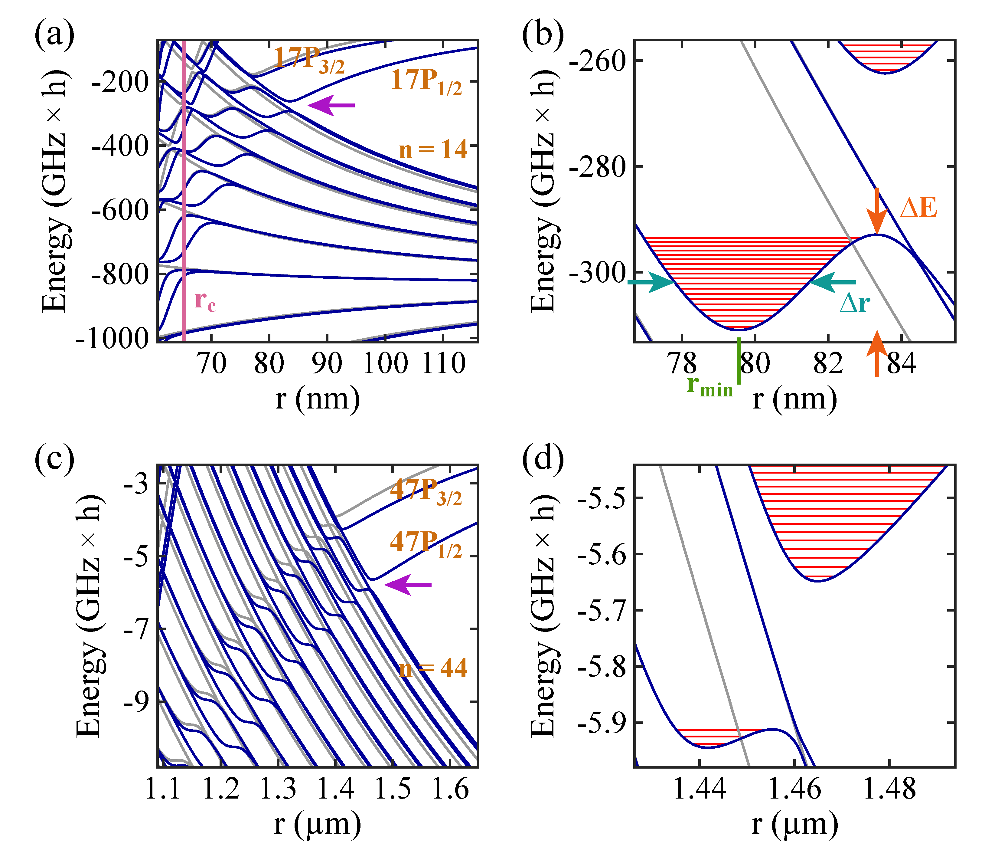
Figure 1. (a) Stark map level structure of a Rb atom in the vicinity of the 17 P state as a function of the internuclear distance r between the atom and the ion. The energy reference is given by the term energy of the 17 P 3 / 2 state at zero electric field corresponding to the value for r . Blue (gray) solid lines represent levels with | m J | = 1 / 2 ( | m J | = 3 / 2 ), where m J is the magnetic quantum number. The purple vertical line marks a critical internuclear distance r c . For r r c , our model breaks down (see text). (b) Magnification of the region indicated by the magenta arrow in Figure 1a, showing the two outermost potential wells. The red solid horizontal lines correspond to vibrational level energies. The parameters Δ E , Δ r , and r min are used to characterize a potential well (see text). (c,d) Stark map and magnification of the vicinity of the 47 P state. Here, the energy reference is the term energy of the 47 P 3 / 2 state at zero electric field.
Atoms 09 00034 g001
Figure 2. Properties of the second outermost potential wells associated with the n P 1 / 2 states of Rb and of corresponding molecular bound states as functions of the principal quantum number n. (a) Depth Δ E (on a logarithmic scale). (b) Width Δ r . (c) Position r min . (d) Number N of vibrational bound states. (e) Energy splitting Δ E v between the vibrational ground state and the first excited vibrational state (on a logarithmic scale). (f) Rotational constant B for a 87 Rb 138 Ba + molecule (on a logarithmic scale).
Atoms 09 00034 g002
Figure 3. (a) Over-barrier motion. The red solid lines represent the Coulomb potential V Cou as given in Equation (11) for two ionic cores located at z = 0 and z = 80 nm on the z-axis (i.e., r = 80 nm ) and an electron at position z. The black solid horizontal lines correspond to the energy of the unperturbed Rydberg level for n = 17 and n = 22 , respectively. (b) Comparison of the critical internuclear distance r c to the internuclear distance r min where the minimum of the second outermost potential well associated with n P 1 / 2 states is located, as a function of n.
Atoms 09 00034 g003
Figure 4. Comparison of wave functions. (a) Upper panel: Potential energy curves in the region of the two outermost potential wells associated with the 17 P 1 / 2 (on the left; see also Figure 1b) and the 27 P 1 / 2 (on the right) states. Blue (gray) solid lines indicate levels with | m J | = 1 / 2 ( | m J | = 3 / 2 ). Black dashed vertical lines mark internuclear distances below which the potential energy landscape is not plotted. The energy reference is the term energy of the 17 P 3 / 2 and 27 P 3 / 2 state, respectively, at zero electric field ( r ). Middle panel: The blue solid lines show the potential energy curve for a Rb 5 S 1 / 2 atom colliding with a Ba + 6 S 1 / 2 ion within the partial wave l = 0 . We choose the ( 1 ) 3 Σ + state to represent the short-range part for r 4 nm (see text). Here, the energy reference corresponds to the atomic asymptote of the two collision partners. The black, magenta, and ocher solid lines are scattering wave functions for atom–ion collision energies E of ( 1 , 0.1 , 0.01 ) mK × k B , respectively. Their amplitudes are scaled for better visibility and are given in arbitrary units. Lower panel: The same as the middle panel but for l = 20 . For the blue solid lines, the angular momentum potential is included. (b,c) Magnifications of parts of Figure 4a. For simplicity, in the upper panels, only the second outermost potential wells associated with the states 17 P 1 / 2 and 27 P 1 / 2 are considered. The red solid lines are the wave functions of vibrational levels with l = 0 (presented by using a scaling factor and given in arbitrary units).
Atoms 09 00034 g004
Figure 5. Examples for coupling of molecular levels. Shown are the potential energy curves in the region around the two outermost molecular potential wells associated with the 27 P 1 / 2 state of Rb. Blue (gray) solid lines indicate levels with | m J | = 1 / 2 ( | m J | = 3 / 2 ). Here, the reference for zero energy is the term energy of the 27 P 3 / 2 state at zero electric field ( r ). The red solid lines correspond to wave functions of vibrational levels with l = 0 . Their amplitudes are scaled for better visibility and are given in arbitrary units. The green arrow illustrates a transition between two neighboring vibrational states within the same potential well, which can be driven by a radio-frequency field. The purple vertical arrow represents a microwave transition between two vibrational states in different potential wells. The cyan vertical arrow indicates a transition from a bound state towards a repulsive potential energy curve.
Atoms 09 00034 g005
Publisher’s Note: MDPI stays neutral with regard to jurisdictional claims in published maps and institutional affiliations.