Article

Curvature Effects on the Regimes of the Lateral van der Waals Force

by
Alexandre P. Costa
1,2,
Lucas Queiroz
2,3,* and
Danilo T. Alves
2
1
Instituto de Física, Universidade de Brasília, Brasília 70910-900, DF, Brazil
2
Faculdade de Física, Universidade Federal do Pará, Belém 66075-110, PA, Brazil
3
Instituto Federal de Educação, Ciência e Tecnologia do Pará, Campus Rural de Marabá, Marabá 68508-970, PA, Brazil
*
Author to whom correspondence should be addressed.
Atoms 2025, 13(7), 61; https://doi.org/10.3390/atoms13070061
Submission received: 30 April 2025 / Revised: 21 June 2025 / Accepted: 24 June 2025 / Published: 25 June 2025

Abstract

Recently, it has been shown that, under the action of the lateral van der Waals (vdW) force due to a perfectly conducting corrugated plane, a neutral anisotropic polarizable particle in vacuum can be attracted not only to the nearest corrugation peak but also to a valley or an intermediate point between a peak and a valley, with such behaviors called peak, valley, and intermediate regimes, respectively. In the present paper, we discuss how the curvature of the corrugated surface affects the occurrence of the mentioned regimes. For this, we calculate the vdW interaction between a polarizable particle and a grounded conducting corrugated cylinder. We consider the corrugations along the azimuthal ( ϕ -direction) angle or along the cylinder axis (z-direction). We show that when the corrugation occurs in the z-direction, the curvature has a small effect on the occurrence of the valley regime. On the other hand, it inhibits the intermediate regimes up to a certain particle–surface distance above which it amplifies the occurrence of this regime. When the corrugation occurs in the ϕ -direction, we show that the curvature inhibits both the valley and intermediate regimes.

1. Introduction

The interaction between a neutral unpolarized, but polarizable, particle and a neutral surface is commonly denominated as a Casimir–Polder (CP) interaction [1]. In the limit of very small particle–surface distances, if compared to the typical wavelength characterizing the optical response of the particle, the CP interaction is also usually called a van der Waals (vdW) interaction. In general, the behavior of the CP and vdW interactions depends on the electromagnetic properties of the surface and its geometry, having important consequences not only in different areas of physics, but also in engineering, chemistry, and biology [2,3,4,5,6,7], with possibilities for applications in micro and nanotechnology opening up as the precision of the experiments that measure them progresses (for examples of experimental works which involve the CP and vdW interactions, see refs. [8,9,10,11,12,13,14,15,16,17,18,19]).
Regarding the dependence of the CP and vdW interactions on the surface geometry, when considering corrugated surfaces in these interactions, lateral forces appear and non-trivial geometric effects can be predicted [20,21,22,23,24,25,26] (we remark that these lateral forces have their origin in quantum fluctuations, which is different, for example, from the case of optical lateral forces acting on chiral particles by means of an applied polarized light [27]). Within this context, using analytical calculations beyond the proximity force approximation (PFA), a recent investigation [24] of the vdW interaction between a neutral polarizable point particle and a corrugated plane led to the prediction that, under the action of the lateral vdW force, an anisotropic particle can be attracted not only toward the nearest corrugation peak (that was already known in the literature), but (surprisingly and counter-intuitively) also to a valley, or to an intermediate point between a peak and valley, with such behaviors called peak, valley and intermediate regimes, respectively [24] (see Figure 1). In ref. [25], considering the point particle immersed in a non-dispersive dielectric medium ϵ 2 and interacting with another medium ϵ 1 , with a corrugated interface between them, it was shown that the diagrams describing the occurrence of the vdW lateral force regimes are not a mere permutation between the peak and valley regimes, when comparing the case ϵ 2 > ϵ 1 with the case ϵ 2 < ϵ 1 . Surprisingly, making ϵ 2 > ϵ 1 generates a highly non-trivial change in the behavior of the diagrams, as well as the emergence of the possibility of a transition between the peak and valley regimes even for isotropic particles. In ref. [26], it was shown how the occurrence of the peak, valley and intermediate regimes is affected by the consideration of realistic dielectric properties for the surface and also of the retardation in the interaction. Specifically, an amplification was found of the occurrence of the valley and intermediate regimes for a spheroidal gold nanoparticle interacting with a corrugated plane also made of gold [26]. Other new non-trivial aspects of the lateral vdW force have also recently been investigated [28,29,30].
In the present paper, we discuss the influence of another factor on the occurrence of the mentioned regimes of the lateral vdW force: the curvature of the surface on which the corrugation is introduced. For this, we start considering the corrugations occurring on the surface of a grounded conducting cylinder [see Figure 2], and calculate the vdW interaction between a polarizable point particle and such a grounded conducting corrugated cylinder. To compute this interaction, we start by calculating the electrostatic potential of a charge in the presence of a grounded conducting corrugated cylinder. This is performed by extending to a cylindrical geometry the perturbative calculations proposed by Clinton, Esrick, and Sacks in ref. [31] (for a pedagogical review of this method, see ref. [32]). In the sequence, combining this result with the prescription performed by Eberlein and Zietal [33] to obtain the vdW interaction between a polarizable point particle and an ideal conducting surface, we calculate the vdW interaction between a polarizable point particle and a grounded conducting corrugated cylinder. We investigate the effects of the curvature of the cylinder on the regimes of the lateral vdW force, comparing these results with those obtained for a plane in ref. [24].
In the literature, the cylindrical geometry was considered in several problems involving the CP and vdW interactions (see, as examples, refs. [33,34,35,36,37,38,39,40,41,42]). However, the study of these interactions by considering a corrugated cylinder has never been addressed, as far as we know. In the present paper, the consideration of a perfectly conducting surface in the vdW regime of the particle–surface interaction enables us to write simpler formulas, which provide a quick estimate of the curvature effects on the occurrence of the peak, valley, and intermediate regimes. In addition, in the same way that the peak, valley and intermediate regimes were primarily found in the context of the vdW interaction [24,25] and further were found in the context of the CP interaction [26] (where the electromagnetic field quantization is taken into account), we expect that the curvature effects on the occurrence of these regimes, found in the present paper for the vdW interaction, can also be naturally found for the CP interaction. Thus, the investigations carried out here can pave an additional way to understanding geometric effects on the electromagnetic quantum vacuum fluctuations, and may be relevant for better controlling of the interaction between a particle and a nonplanar surface.
The paper is organized as follows. In Section 2, we present the approach used to compute the vdW interaction between a neutral particle and a corrugated cylinder, and we discuss some applications. In Section 3, we compute the vdW interaction for the mentioned situation, and we apply our results to the case of a sinusoidal corrugation. In Section 4, we present our final comments.

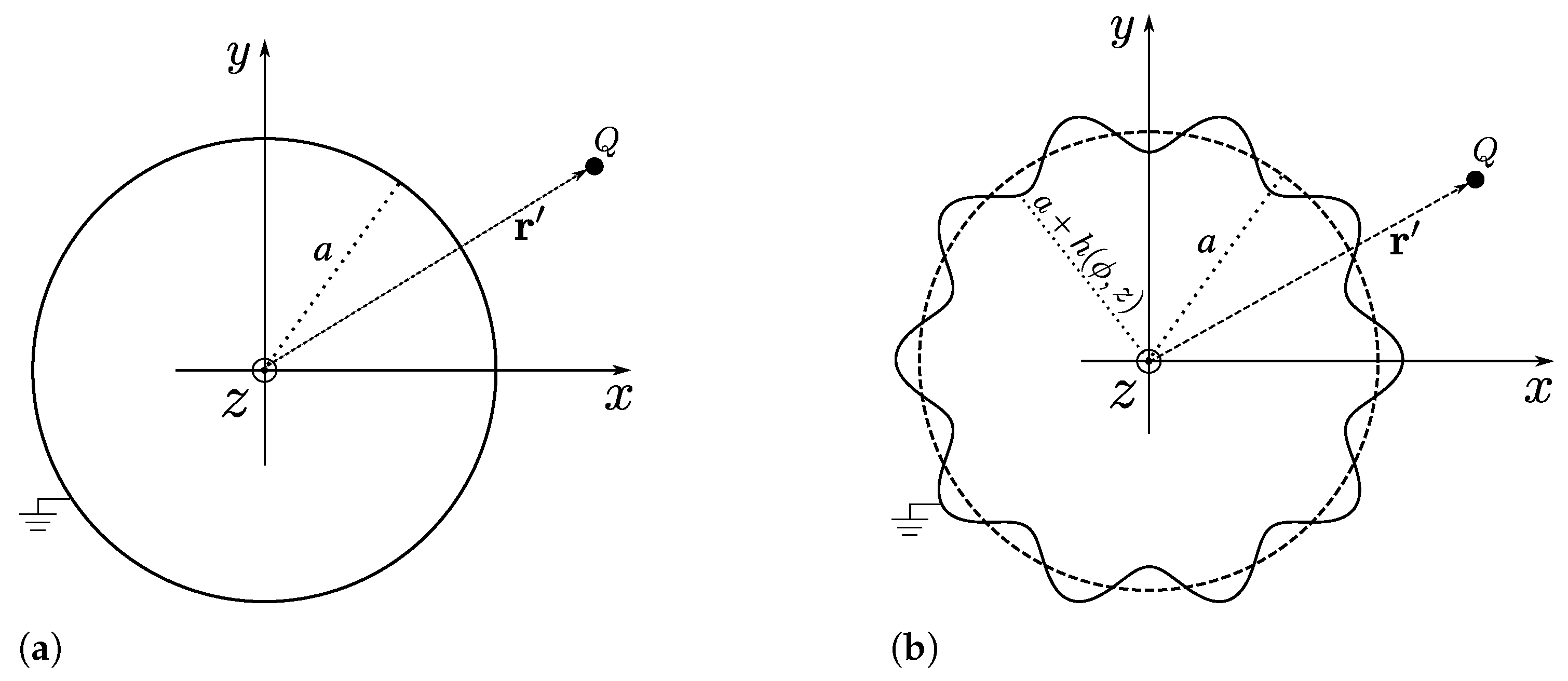
2. Point Charge in the Presence of a Corrugated Cylinder

2.1. The Solution of the Poisson’s Equation

Let us start by considering the problem of a point charge Q, located at the position given by the vector r , with cylindrical coordinates ( ρ , ϕ , z ) , and interacting with an infinite grounded conducting cylinder with radius a [see Figure 2a]. The Green’s function related to the Poisson’s equation for this problem is known from ref. [43], and is given by
G r , r = 2 j d k 2 π e i k z z e i j ϕ ϕ K j k ρ > I j k ρ < K j k ρ < I j k a K j k a ,
where ρ < and ρ > refer, respectively, to the smaller and the larger between ρ and ρ , and, to avoid overloading, we are using j j = + + .
Now, let us consider the previous problem and introduce in the cylinder surface a corrugation described by ρ = a + h ( ϕ , z ) , where h ( ϕ , z ) describes a suitable modification on the cylinder surface, as shown in Figure 2b.
In this situation, the problem consists of finding the solution of Poisson’s equation
2 G r , r = 4 π ρ δ ρ ρ δ ϕ ϕ δ z z ,
under the boundary conditions
G r , r ρ = a + η h ϕ , z = 0 ,
G r , r | r | | r | 0 ,
where η is an arbitrary auxiliary parameter such that 0 η 1 , where for η = 0 , we recover a cylinder with radius a, and for η = 1 , we recover the corrugated cylinder described by h ( ϕ , z ) . We look for a perturbative solution for the Green’s function which is written in terms of the parameter η as
G ( r , r ) = G ( 0 ) ( r , r ) + n = 1 η n G ( n ) ( r , r ) ,
where G ( 0 ) ( r , r ) is the unperturbed solution [corresponding to the situation shown in Figure 2a], and G ( n ) ( r , r ) are the perturbative corrections to G ( 0 ) due to the surface corrugation. Substituting Equation (5) into (3), and expanding in powers of η h ( ϕ , z ) , we obtain boundary conditions for G ( 0 ) ( r , r ) and G ( n ) ( r , r ) at ρ = a , which are given by
G 0 r , r | ρ = a = 0 ,
G n r , r | ρ = a = m = 1 n h ( ϕ , z ) m 1 m ! 𝜕 m 𝜕 ρ m G n m r , r | ρ = a .
In order to solve Equation (2), it is convenient to write the Green’s function as [44]
G r , r = j d k 2 π G ˜ j ρ , k , r e i k z e i j ϕ ,
where
G ˜ j ρ , k , r = 0 2 π d ϕ 2 π d z G r , r e i k z e i j ϕ .
Similarly, we can write the ϕ and z delta functions as
δ ϕ ϕ = 1 2 π j e i j ϕ ϕ ,
δ z z = d k 2 π e i k z z .
In this way, substituting Equations (8), (10), and (11) into (2), one obtains
1 ρ 𝜕 𝜕 ρ ρ 𝜕 𝜕 ρ j 2 ρ 2 + k 2 G ˜ j ρ , k , r = 2 ρ δ ρ ρ e i ( j ϕ + k z ) .
We can also substitute Equation (8) into (5)–(7), which leads to
G ˜ j ρ , k , r = G ˜ j ( 0 ) ρ , k , r + n = 1 η n G ˜ j ( n ) ρ , k , r ,
and
G ˜ j 0 ρ , k , r | ρ = a = 0 ,
G ˜ j n ρ , k , r | ρ = a = m = 1 n j d k 2 π h ˜ m , j , j k k 1 m ! 𝜕 m 𝜕 ρ m G ˜ j n m ρ , k , r | ρ = a ,
where
h ˜ m , j , j k k = 0 2 π d ϕ 2 π d z e i z k k e i ϕ j j h ( ϕ , z ) m .
Substituting Equation (13) into (12), we obtain differential equations for G ˜ j ( 0 ) ρ , k , r and G ˜ j ( n ) ρ , k , r , which are given by
1 ρ 𝜕 𝜕 ρ ρ 𝜕 𝜕 ρ j 2 ρ 2 + k 2 G ˜ j 0 ρ , k , r = 2 ρ δ ρ ρ e i ( j ϕ + k z ) ,
1 ρ 𝜕 𝜕 ρ ρ 𝜕 𝜕 ρ j 2 ρ 2 + k 2 G ˜ j n ρ , k , r = 0 ( n 1 ) .
The solution of Equation (17), with boundary conditions given by Equations (14) and
G ˜ j ( 0 ) ρ , k , r ρ ρ 0 ,
can be written as
G ˜ j 0 ρ , k , r = 2 e i j ϕ e i k z K j k ρ > I j k ρ < K j k ρ < I j k a K j k a ,
where I j and K j are the modified Bessel functions of the first and second kind, respectively. In this way, the solution for G 0 r , r can be obtained from Equation (8), so that one obtains
G 0 r , r = 2 j d k 2 π e i k z z e i j ϕ ϕ K j k ρ > I j k ρ < K j k ρ < I j k a K j k a ,
which, as expected, coincides with Equation (1).
The solution of Equation (18) with the boundary conditions given by Equation (15) and
G ˜ j n ρ , k , r ρ ρ 0 ,
can be written as
G ˜ j n ρ , k , r = m = 1 n j K j k ρ K j k a d k 2 π h ˜ m , j , j k k 1 m ! 𝜕 m 𝜕 ρ m G ˜ j n m ρ , k , r ρ = a .
From Equation (8), one can find the solution for G n r , r , which can be written as
G ( n ) ( r , r ) = m = 1 n j , j d k 2 π d k 2 π ×   K j ( | k | ρ ) K j ( | k | a ) e i k z e i j ϕ h ˜ m , j , j ( k k ) m ! 𝜕 m 𝜕 ρ m G ˜ j ( n m ) ( ρ , k , r ) ρ = a .
Thus, the solution of Equation (2) for the problem of a point charge in the presence of a corrugated cylinder is given by Equation (5) (with η = 1 ), with G ( 0 ) and G ( n ) given by Equations (21) and (24), respectively. This result for the Green function extends to a cylindrical geometry the correspondent one found in ref. [31] for the case of a corrugated plane. We remark that this perturbative solution is increasingly better as max h ϕ , z a , d , with d = ρ a being the distance from the charge to the surface of the cylinder without the corrugations. In other words, as max h ϕ , z becomes smaller than a and d, the faster our perturbative solution converges and fewer perturbative corrections are needed to obtain a good approximate solution for the problem. Next, we apply the obtained results to compute the interaction between the charge and the corrugated cylinder.

2.2. Electrostatic Interaction Energy Between a Point Charge and a General Corrugated Cylinder

The interaction energy between a unitary point charge and the corrugated cylinder shown in Figure 2b is given, in Gaussian units, by
U r = G r , r 1 | r r | r = r ,
where G r , r is given by Equation (5) (with η = 1 ), with G ( 0 ) and G ( n ) given by Equations (21) and (24), respectively. By using the following expansion for 1 / | r r | [44,45]
1 | r r | = j d k π e i k z z e i j ϕ ϕ K j k ρ > I j k ρ < ,
we can write U r as
U r = G H 0 r , r + n = 1 G n r , r r = r ,
where G H 0 r , r is given by
G H 0 r , r = j d k π e i k z z e i j ϕ ϕ K j k ρ > K j k ρ < I j k a K j k a .
By performing r = r , we obtain
U r = U 0 ( r ) + n = 1 U ( n ) ( r ) ,
where
U 0 ( r ) = j d k π I j k a K j k a K j k ρ 2
is the interaction between the charge and an infinite grounded conducting cylinder [as shown in Figure 2a]. The functions
U ( n ) ( r ) = m = 1 n j , j d k 2 π d k 2 π ×   K j ( | k | ρ ) K j ( | k | a ) h ˜ m , j , j ( k k ) m ! 𝜕 m 𝜕 ρ m G ˜ j ( n m ) ( ρ , k , r ) ρ = a e i k z e i j ϕ ,
with h ˜ m , j , j and G ˜ j ( n m ) given by Equations (16) and (23), respectively, are the corrections of U 0 due to the presence of corrugations in the cylinder surface [as shown in Figure 2b]. Note that, since U r depends on ϕ and z, a lateral electrostatic force [parallel to the surface of the reference cylinder shown in Figure 2a] acting on the charge arises, and it occurs due to the presence of corrugations on the cylinder surface. Moreover, the dependence of U r on ϕ and z belongs specifically to the perturbative corrections U ( n ) . Thus, since we are interested only in the behavior of the mentioned lateral electrostatic force, hereafter, we focus our attention only on U ( n ) .

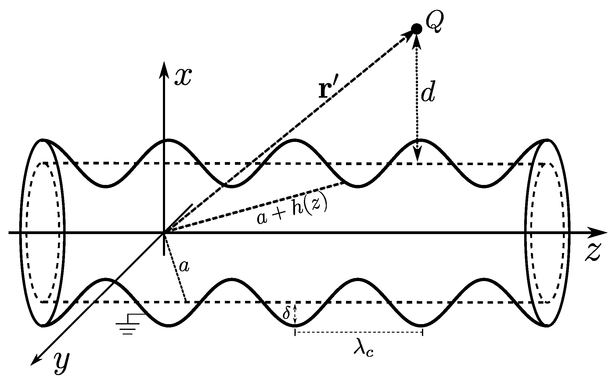
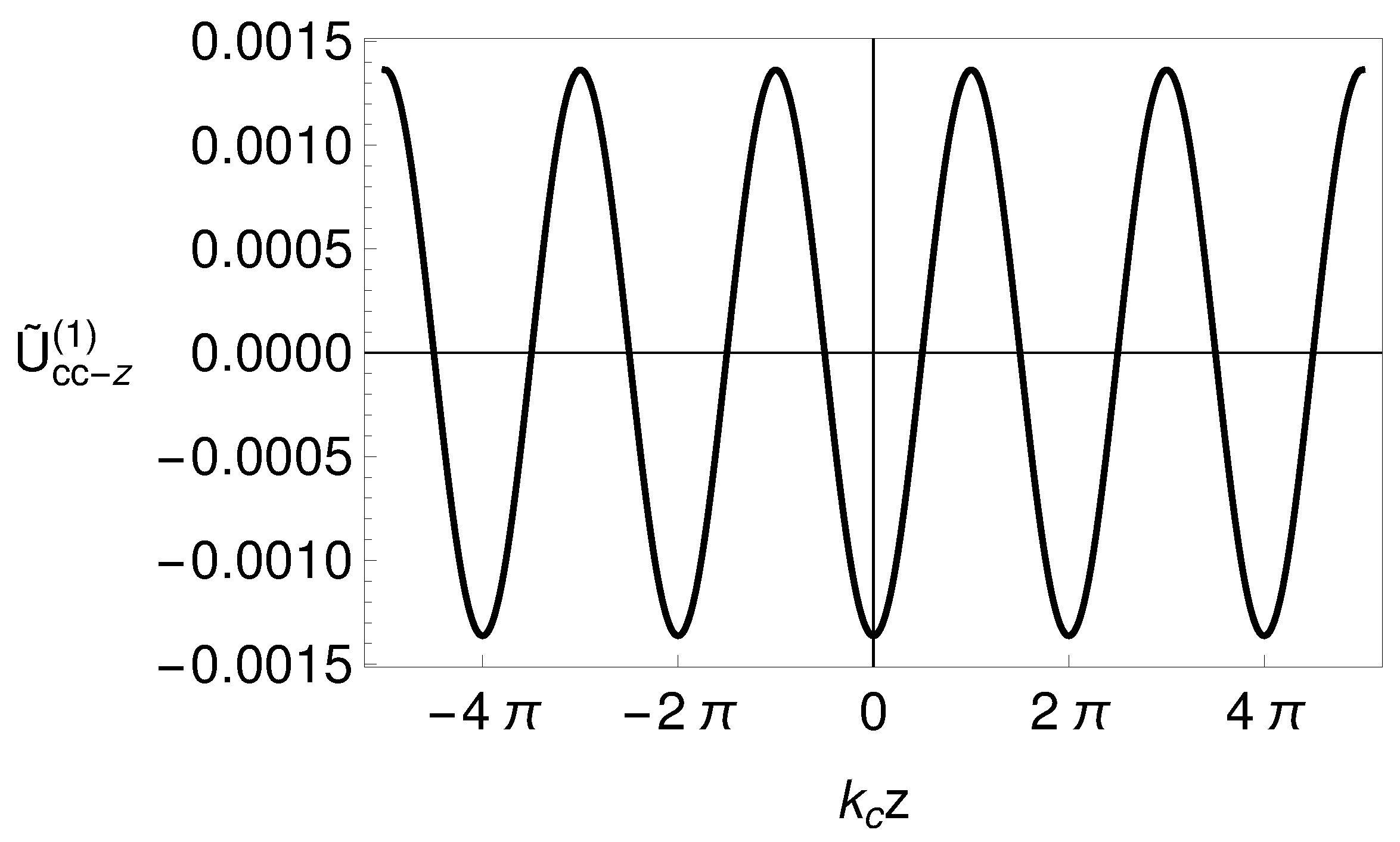
2.3. Electrostatic Interaction Energy for a Cylinder with a Sinusoidal Corrugation Along the z-Direction

Let us consider a sinusoidal corrugation profile described by
h z = δ cos k c z ,
where δ is the amplitude of the corrugation and k c = 2 π / λ c , with λ c being the wavelength of the corrugation (see Figure 3).
Let us also consider an approximate solution for this case which takes into account only the correction for n = 1 in Equation (29). We remark that this approximate solution is increasingly better as δ a , d , since the smaller δ becomes compared to a and d, the smaller the contributions from higher perturbative corrections in the interaction. In this way, from Equation (31), one obtains that U ( 1 ) can be written, for the corresponding case, as
U cc - z 1 r = δ a π cos k c z j d k K j k + k c d + a K j k + k c a K j k d + a K j k a ,
where the subscript “cc-z” refers to the result for a corrugated cylinder with corrugation occurring along the z-direction. In Figure 4, we show the behavior of U ˜ cc - z 1 = U cc - z 1 / ( δ / a 2 π ) versus k c z , where one can see that the minimum values of U cc - z 1 are located over the corrugation peaks. This means that the lateral electrostatic force acting on the charge always attracts it to the nearest peak of the corrugation. From Equation (33), one sees that such behavior occurs for any value of a, d, and k c , since the integrate and summation are positive for any value of these parameters, and all the dependence of U cc - z 1 on z is inserted in the cosine function.
It is also interesting to compare Equation (33) with the corresponding result for a corrugated plane, since it shows us the effect of the curvature of the surface on the lateral electrostatic force. From ref. [31], one can find, perturbatively, the interaction between a point charge and a corrugated plane described by Equation (32), whose first perturbative correction of the interaction is given by
U cp 1 r = δ 4 k c 2 cos k c z K 2 k c d ,
where the subscript “cp” refers to the result for a corrugated plane. In Figure 5, we show the behavior of the ratio U cc - z 1 / U cp 1 versus d / a , for different values of k c a . For d / a 1 , one sees that U cc - z 1 / U cp 1 1 , which is expected, since as the charge approaches to the cylinder, the curvature effects vanish. On the other hand, as d / a increases, the presence of curvature on the corrugated surface becomes more relevant and produces a weakening in U cc - z 1 . Regarding the lateral electrostatic forces F cc - z = 𝜕 z U cc - z ( 1 ) and F cp = 𝜕 z U cp ( 1 ) , the behavior of the ratio F cc - z / F cp is exactly the same as shown in Figure 5, which means that the lateral electrostatic force for a cylinder corrugated in z-direction is weaker than that for a corrugated plane.

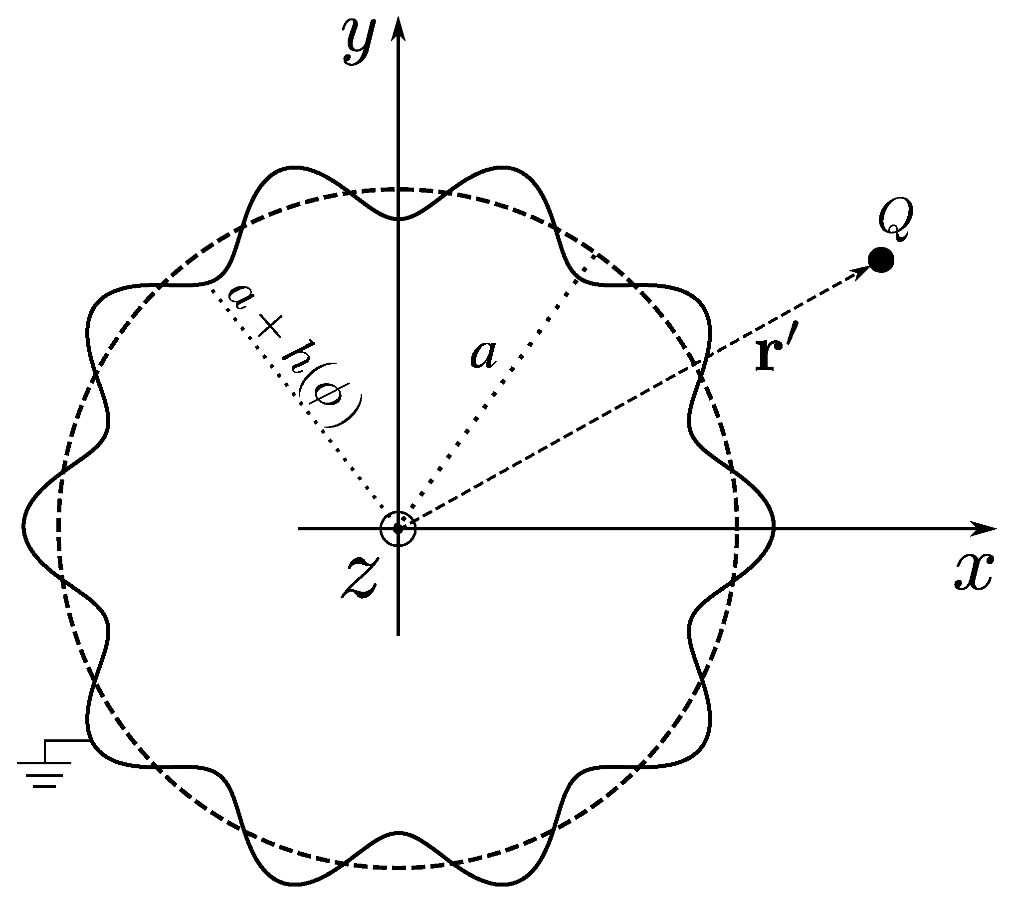
2.4. Electrostatic Interaction Energy for a Cylinder with a Sinusoidal Corrugation Along the ϕ -Direction

Let us now consider a sinusoidal corrugation profile described by
h ϕ = δ cos k c a ϕ ,
where δ is the amplitude of the corrugation, k c = 2 π / λ c , with λ c being the wavelength of the corrugation and a is the radius of the cylinder (see Figure 6). We remark that in this situation, the number of oscillations of the corrugation is constrained to the length of the cylinder circumference, so that λ c and N must satisfy the constraint
N λ c = 2 π a N = k c a ,
where N N * .
Let us also consider an approximate solution for this case which takes into account only the correction of n = 1 in Equation (29). We remark that this approximate solution is increasingly better as δ a , d , since the smaller δ becomes compared to a and d, the smaller the contributions from higher perturbative corrections in the interaction. In this way, from Equation (31), one obtains that U ( 1 ) can be written, for the corresponding case, as
U cc - ϕ 1 r = δ a π cos k c a ϕ j d k K j k d + a K j k a K j + k c a k d + a K j + k c a k a .
where the subscript “cc- ϕ ” refers to the result for a corrugated cylinder with corrugation occurring along the ϕ -direction. In Figure 7, we show the behavior of U ˜ cc - ϕ 1 = U cc - ϕ 1 / ( δ / a 2 π ) versus ϕ , where one can see that the minimum values of U cc - ϕ 1 are located over the corrugation peaks. This means that the lateral force acting on the charge always attracts it to the nearest peak of the corrugation. Besides this, from Equation (37), one sees that such behavior occurs for any value of a, d, and k c , since the integrate and summation are positive for any value of these parameters, and all the dependence of U cc - ϕ 1 on ϕ is inserted in the cosine function.
It is also interesting to compare Equation (37) with Equation (34), since it shows us the effect of the curvature of the surface on the lateral electrostatic force. In Figure 8, we show the behavior of the ratio U cc - ϕ 1 / U cp 1 versus d / a , for different values of k c a . From this figure, for d / a 1 , one sees the curvature effects vanishing, since U cc - ϕ 1 / U cp 1 1 . On the other hand, as d / a increases, the presence of curvature on the corrugated surface becomes more relevant, producing an amplification of the potential U cc - ϕ 1 (note that this is different from the case in which the cylinder corrugation occurs in the z-direction). Regarding the lateral electrostatic forces F cc - ϕ = ( 1 / ρ ) 𝜕 ϕ U cc - ϕ ( 1 ) and F cp = 𝜕 z U cp ( 1 ) , the behavior of the ratio F cc - ϕ / F cp is similar to that shown in Figure 8, which means that the lateral electrostatic force for a cylinder corrugated in ϕ -direction is stronger than that for a corrugated plane.

3. The van der Waals Interaction Between a Polarizable Point Particle and a Corrugated Cylinder

3.1. Interaction Energy for a General Corrugated Cylinder

Let us consider a neutral polarizable point particle, put at r 0 = ρ 0 ρ ^ + z 0 z ^ , in the presence of a grounded conducting corrugated cylinder with radius a, as illustrated in Figure 2b. The vdW interaction U vdW between this particle and the corrugated cylinder can be computed by combining the Eberlein–Zietal formula from ref. [33] with the solution for the Green’s function for the problem of a charge in the presence of a grounded conducting corrugated cylinder [Equation (5) with η = 1 , and with G ( 0 ) and G ( n ) given by Equations (21) and (24)]. The mentioned Eberlein–Zietal formula is given by
U vdW ( r 0 ) = 1 8 π ϵ 0 i , j d ^ i d ^ j i j G H ( r , r ) r = r = r 0 ,
where d ^ i are the components of the dipole moment operator and d ^ i d ^ j is the expectation value of d ^ i d ^ j . The function G H is the homogeneous part of the Green’s function G of the Laplacian operator, so that it satisfies the Laplace’s equation and can be written as
G H r , r = G r , r 1 | r r | .
We remark that this function contains all the information about the geometry of the surface, and that Equation (38) can be applied only when the surface is described as a nondispersive dielectric or an ideal conductor. In addition, Equation (38) also has the condition of being applicable only when the dimensions of the particle are very small when compared to its distance from the surface, so that the particle can be considered as a point particle. Thus, when these conditions are satisfied, Equation (38) can describe the vdW interaction of a polarizable point particle with a surface of any geometry, as long as the G H function of the corresponding problem is known. Applications of Equation (38) can be found, for instance, in refs. [24,25,33,46,47,48,49].
For simplicity, let us focus on an approximate solution for our problem which takes into account only the correction of n = 1 in Equation (24). We remark that this approximate solution is increasingly better as δ a , d , since the smaller δ becomes compared to a and d, the smaller the contributions from higher perturbative corrections in the interaction. Thus, by computing G H using Equation (39) and substituting it into Equation (38), one obtains that the vdW interaction can be written as U vdW U vdW ( 0 ) + U vdW ( 1 ) . The first term U vdW ( 0 ) , which can be written as
U vdW ( 0 ) r 0 = 1 8 π ϵ 0 Ξ ρ d ^ ρ 2 + Ξ ϕ d ^ ϕ 2 + Ξ z d ^ z 2 ,
where
Ξ ρ = 1 π j d k I j k a K j k a 𝜕 ρ 0 K j k ρ 0 2 ,
Ξ ϕ = 1 π ρ 0 2 j d k j 2 I j k a K j k a K j k ρ 0 2 ,
Ξ z = 1 π j d k k 2 I j k a K j k a K j k ρ 0 2 ,
is the vdW interaction energy between the particle and the cylinder without corrugations, which was first obtained in ref. [33]. The second term, U vdW ( 1 ) , is the first-order correction to U vdW ( 0 ) due to the corrugation in the cylinder surface. Besides this, it is obtained by substituting G ( 1 ) , given by Equation (24) with n = 1 , in the Eberlein–Zietal formula [Equation (38)], obtaining
U vdW 1 ( r 0 ) = 1 8 π ϵ 0 ×   [ d ^ ρ 2 I ρ ρ + d ^ ϕ 2 I ϕ ϕ + d ^ z 2 I z z + d ^ ρ d ^ ϕ I ρ ϕ + d ^ ρ d ^ z I ρ z + d ^ ϕ d ^ z I ϕ z ] ,
where
I ρ ρ = 2 a j , j d k 2 π d k 2 π h ˜ 1 , j , j ( k , k ) e i z ( k k ) e i ϕ ( j j ) 𝜕 ρ K j ( | k | ρ ) K j ( | k | a ) 𝜕 ρ K j ( | k | ρ ) K j ( | k | a ) ,
I ϕ ϕ = 2 a ρ 2 j , j d k 2 π d k 2 π h ˜ 1 , j , j ( k , k ) j j e i z ( k k ) e i ϕ ( j j ) K j ( | k | ρ ) K j ( | k | a ) K j ( | k | ρ ) K j ( | k | a ) ,
I z z = 2 a j , j d k 2 π d k 2 π h ˜ 1 , j , j ( k , k ) k k e i z ( k k ) e i ϕ ( j j ) K j ( | k | ρ ) K j ( | k | a ) K j ( | k | ρ ) K j ( | k | a ) ,
I ρ ϕ = 2 i a ρ j , j d k 2 π d k 2 π ×   h ˜ 1 , j , j ( k , k ) e i z ( k k ) e i ϕ ( j j ) j K j ( | k | ρ ) 𝜕 ρ K j ( | k | ρ ) j 𝜕 ρ K j ( | k | ρ ) K j ( | k | ρ ) K j ( | k | a ) K j ( | k | a ) ,
I ρ z = 2 i a j , j d k 2 π d k 2 π ×   h ˜ 1 , j , j ( k , k ) e i z ( k k ) e i ϕ ( j j ) k K j ( | k | ρ ) 𝜕 ρ K j ( | k | ρ ) k 𝜕 ρ K j ( | k | ρ ) K j ( | k | ρ ) K j ( | k | a ) K j ( | k | a ) ,
I ϕ z = 2 a ρ j , j d k 2 π d k 2 π h ˜ 1 , j , j ( k , k ) k j + k j e i z ( k k ) e i ϕ ( j j ) K j ( | k | ρ ) K j ( | k | a ) K j ( | k | ρ ) K j ( | k | a ) .
with h ˜ 1 , j , j given by Equation (16) with m = 1 . Note that the lateral force that acts on the particle arises due to the dependence of U vdW ( 1 ) on ϕ and z. Since we are interested only in the behavior of this force, hereafter, we focus our attention only on U vdW ( 1 ) .

3.2. Interaction Energy for a Cylinder with a Sinusoidal Corrugation Along the z-Direction

Let us consider a sinusoidal corrugation profile described by Equation (32). For this situation, U vdW ( 1 ) can be written as
U vdW , cc - z 1 r 0 = δ 8 π ϵ 0 A cc - z cos k c z 0 Δ cc - z ,
where A cc - z = B cc - z 2 + C cc - z 2 , and Δ cc - z is a nontrivial phase function defined by
Δ cc - z = arctan B cc - z C cc - z ,
with
B cc - z = d ^ ρ d ^ z R ρ z cc - z ,
C cc - z = d ^ ρ 2 R ρ ρ cc - z + d ^ ϕ 2 R ϕ ϕ cc - z + d ^ z 2 R z z cc - z ,
and the functions R i j cc - z being defined by
R ρ ρ cc - z = 4 π a j = 0 0 d k 𝜕 ρ 0 K j k k c 2 ρ 0 K j k k c 2 a 𝜕 ρ 0 K j k + k c 2 ρ 0 K j k + k c 2 a ,
R ϕ ϕ cc - z = 4 π a 1 ρ 0 2 j = 1 0 d k j 2 K j k k c 2 ρ 0 K j k k c 2 a K j k + k c 2 ρ 0 K j k + k c 2 a ,
R z z cc - z = 4 π a j = 0 0 d k k 2 k c 2 2 K j k k c 2 ρ 0 K j k k c 2 a K j k + k c 2 ρ 0 K j k + k c 2 a ,
R ρ z cc - z = 4 π a j = 0 0 d k k K j k ρ 0 K j k a 𝜕 ρ 0 K j k + k c ρ 0 K j k + k c a 𝜕 ρ 0 K j k k c ρ 0 K j k k c a .
From Equation (51), considering the behavior of U ( 1 ) with respect to z 0 , one can see that the stable equilibrium points of U ( 1 ) can be over the corrugation peaks ( Δ cc - z = π ) , valleys ( Δ cc - z = 0 ) or over intermediate points between a peak and a valley ( Δ cc - z 0 , π ) . Such possibilities were called in ref. [24] peak, valley, and intermediate regimes, respectively. In refs. [25,28], we showed how modifications on the electromagnetic properties of the surface affect the occurrence of these regimes. Otherwise, with Equations (51)–(58), we can now study how modifications on the curvature of the corrugated surface affect the occurrence of these regimes. For this, let us consider a class of cylindrically symmetric polarizable particles, whose tensor d ^ i d ^ j diagonalized, in cylindrical coordinates, is represented by d ^ i d ^ j = diag d ^ n 2 , d ^ n 2 , d ^ p 2 , with d ^ p 2 > d ^ n 2 . For a general orientation of this particle, the components of d ^ i d ^ j in terms of the spherical angles ( θ , φ ) , with respect to the coordinates system ( ρ , ϕ , z ) , are given by:
d ^ ρ 2 = d ^ p 2 β + 1 β sin 2 θ cos 2 φ ,
d ^ ϕ 2 = d ^ p 2 β + 1 β sin 2 θ sin 2 φ ,
d ^ z 2 = d ^ p 2 β + 1 β cos 2 θ ,
d ^ ρ d ^ ϕ = d ^ p 2 1 β 2 sin 2 φ sin 2 θ ,
d ^ ρ d ^ z = d ^ p 2 1 β 2 sin 2 θ cos φ ,
d ^ ϕ d ^ z = d ^ p 2 1 β 2 sin 2 θ sin φ ,
with β = d ^ n 2 / d ^ p 2 .
Let us start analyzing the curvature effects on the occurrence of the peak and valley regimes. As mentioned above, we have peak and valley regimes when Δ cc - z = π , and Δ cc - z = 0 , respectively. In this way, from Equations (52)–(54), one sees that such regimes can only occur when B cc - z = 0 , which occurs when d ^ ρ d ^ z = 0 (the particle is oriented such that its axis coincides with ρ , ϕ , or z). In addition, we have one or the other of these regimes depending on the sign of C cc - z , where we have the valley regime when it is positive, and the peak regime when it is negative [see Equation (52)]. By considering the particle oriented such that its axis is parallel to the z-axis ( θ = 0 ) , in Figure 9 we show the behaviors of C cc - z and the corresponding function (named C cp ) for the case of a corrugated plane, which was calculated in ref. [24]. In Figure 9, one notes that, for the case of a corrugation occurring in the z-direction, the presence of curvature on the corrugated surface has a small effect on the occurrence of the valley regime, since C cc - z , when compared with C cp , changes its sign by a slightly different value of d for different values of a. One can also see that, as a increases, the behavior of C cc - z , for a given value of d, approaches to the behavior of C cp , which means that the curvature effects vanish, as expected. This is reinforced in the inset, where we show the behavior of the ratio C cc - z / C cp in terms of d (the sudden oscillation of the curves between d = 0.54   μ m and d = 0.6   μ m occurs due to the change of sign of the functions C cc - z and C cp , which occurs in this interval).
Now, let us analyze the curvature effects on the occurrence of the intermediate regimes. As mentioned above, we have intermediate regimes when Δ cc - z 0 , π , which can only occur when B cc - z 0 , which occurs when d ^ ρ d ^ z 0 (the particle is oriented such that its axis do not coincide with ρ , ϕ , or z). By considering the particle oriented with θ = π / 6 and φ = 0 , in Figure 10, we show the behaviors of Δ cc - z and Δ cp . In Figure 10, one notes that, for the case of a corrugation occurring in the z-direction, the presence of curvature on the corrugated surface can inhibit the occurrence of the intermediate regimes up to a certain value of d, above which it begins to amplify the occurrence of the effect. Lastly, as expected, Δ cc - z approaches to Δ cp as a increases, meaning that the curvature effect decreases by increasing a.
We remark that the previous results are affected by the particle anisotropy, which is described by the factor β . For β = 1 , we have an isotropic particle (since d ^ p 2 = d ^ n 2 ), and the valley and intermediate regimes vanish. On the other hand, for β 0 , we have a particle with a strong anisotropy in the direction of its symmetry axis (since d ^ p 2 d ^ n 2 ), and this consideration gives us the best results for the occurrence of the valley and intermediate regimes. In this way, starting from β 0 , as this factor increases and approaches to 1, the occurrence of valley and intermediate regimes is reduced. It is worth mentioning that for a nanoparticle, its anisotropy is directly related to its shape, such that, β 0 describes a needle-like particle, whereas β = 1 describes a spherical one.
Lastly, the previous results are also affected by the particle orientation. As an example, one can obtain that the consideration of a particle oriented in the z-direction gives us the best results for the occurrence of the valley regime, and that, starting from this orientation, as it is rotated in the ϕ z plane and approaches to the ϕ -direction, the occurrence of the valley regime is reduced, vanishing when it is oriented in the ϕ -direction.

3.3. Interaction Energy for a Cylinder with a Sinusoidal Corrugation Along the ϕ -Direction

Let us now consider a sinusoidal corrugation profile described by Equation (35). For this situation, U vdW ( 1 ) can be written as
U vdW , cc - ϕ 1 r 0 = δ 8 π ϵ 0 A cc - ϕ cos k c a ϕ 0 Δ cc - ϕ ,
where A cc - ϕ = B cc - ϕ 2 + C cc - ϕ 2 , and Δ cc - ϕ is a nontrivial phase function defined by
Δ cc - ϕ = arctan B cc - ϕ C cc - ϕ ,
with
B cc - ϕ = d ^ ρ d ^ ϕ R ρ ϕ cc - ϕ ,
C cc - ϕ = d ^ ρ 2 R ρ ρ cc - ϕ + d ^ ϕ 2 R ϕ ϕ cc - ϕ + d ^ z 2 R z z cc - ϕ ,
and the functions R i j cc - ϕ being defined by
R ρ ρ cc - ϕ = 2 π a 0 d k j = 0 𝜕 ρ 0 K j k ρ 0 K j k a 𝜕 ρ 0 K j + k c a k ρ 0 K j + k c a k a + 𝜕 ρ 0 K j k c a k ρ 0 K j k c a k a ,
R ϕ ϕ cc - ϕ = 2 π a ρ 0 2 0 d k j = 1 ×   j K j ( | k | ρ 0 ) K j ( | k | a ) ( j + k c a ) K j + k c a ( | k | ρ 0 ) K j + k c a ( | k | a ) + ( j k c a ) K j k c a ( | k | ρ 0 ) K j k c a ( | k | a ) ,
R z z cc - ϕ = 2 π a 0 d k j = 0 k 2 K j ( | k | ρ 0 ) K j ( | k | a ) K j + k c a ( | k | ρ 0 ) K j + k c a ( | k | a ) + K j k c a ( | k | ρ 0 ) K j k c a ( | k | a ) ,
R ρ ϕ cc - ϕ = 4 π a ρ 0 0 d k j = 1 j K j k ρ 0 K j k a 𝜕 ρ 0 K j + k c a k ρ 0 K j + k c a k a 𝜕 ρ 0 K j k c a k ρ 0 K j k c a k a .
Similar to the case of a corrugation occurring in the z-direction, from Equation (65), considering the behavior of U ( 1 ) with respect to ϕ 0 , one can see that the stable equilibrium points of U ( 1 ) can be over the corrugation peaks ( Δ cc - ϕ = π ) , valleys ( Δ cc - ϕ = 0 ) or over intermediate points between a peak and a valley ( Δ cc - ϕ 0 , π ) . In other words, we can have peak, valley, and intermediate regimes, depending on the value of Δ cc - ϕ . With Equations (65)–(72), we can also study how modifications on the curvature of the corrugated surface affect the occurrence of these regimes. For this, let us consider again cylindrically symmetric polarizable particles, whose components of the tensor d ^ i d ^ j for a general orientation of this particle are given in Equations (59)–(64).
Let us start analyzing the curvature effects on the occurrence of the peak and valley regimes. As mentioned above, we have peak and valley regimes when Δ cc - ϕ = π , and Δ cc - ϕ = 0 , respectively. In this way, from Equations (66)–(68), one sees that such regimes can only occur when B cc - ϕ = 0 , which occurs when d ^ ρ d ^ ϕ = 0 (the particle is oriented such that its axis coincides with ρ , ϕ , or z). In addition, we have one or the other of these regimes depending on the sign of C cc - ϕ , where we have the valley regime when it is positive, and the peak regime when it is negative [see Equation (66)]. By considering the particle oriented such that its axis is parallel to the ϕ -axis ( θ = π / 2 , φ = π / 2 ) , in Figure 11, we show the behaviors of C cc - ϕ and C cp . In Figure 11, one notes that, for the case of a corrugation occurring in the ϕ -direction, the presence of curvature on the corrugated surface inhibits the occurrence of the valley regime, since C cc - ϕ , when compared with C cp , changes its sign at higher values of d by decreasing a. Such behavior can be related to the fact that, in this case, the curvature of the cylinder occurs in the same direction as the oscillations of the corrugation, i.e, modifications on the curvature of the cylinder modify the structure of the corrugation itself. Despite this, one can also see that, as a increases, the behavior of C cc - ϕ , for a given value of d, approaches to the behavior of C cp , which means that the curvature effects vanish, as expected.
On the other hand, as d increases, the curvature effects become higher, which can be better seen from the inset of Figure 11, where we show the behavior of the ratio C cc - ϕ / C cp in terms of d.
Now, let us analyze the curvature effects on the occurrence of the intermediate regimes. As mentioned above, we have intermediate regimes when Δ cc - ϕ 0 , π , which can only occur when B cc - ϕ 0 , which occurs when d ^ ρ d ^ ϕ 0 (the particle is oriented such that its axis do not coincide with ρ , ϕ , or z). By considering the particle oriented with θ = π / 2 and φ = π / 3 , in Figure 12, we show the behaviors of Δ cc - ϕ and Δ cp . In Figure 12, one notes that, for the case of a corrugation occurring in the ϕ -direction, the presence of curvature on the corrugated surface also inhibits the occurrence of the intermediate regimes by decreasing a. Otherwise, as expected, Δ cc - ϕ approaches to Δ cp as a increases, meaning that the curvature effect vanishes for a d .
As in the previous section, these results are affected by the particle anisotropy and its orientation. For β = 1 , the valley and intermediate regimes vanish, since we have an isotropic particle, whereas for β 0 , we have the best results for the occurrence of the valley and intermediate regimes. Besides this, as an example of the particle orientation dependence, when it is oriented in the ρ - or z-direction, one can obtain that we only have a peak regime.

4. Final Remarks

We studied how the peak, valley, and intermediate regimes for the lateral vdW force are affected by modifications on the geometric properties of the surface on which the corrugation is introduced. Our main formulas are given by Equations (44)–(50), which, applied to a sinusoidal corrugation, result in Equations (51) and (65). When the corrugation occurs in the z-direction, [Equation (51)], it was shown that the presence of curvature on the corrugated surface has a small effect on the occurrence of the valley regime, practically not affecting it. On the other hand, for the intermediate regimes, the presence of curvature inhibits their occurrence up to a certain particle–surface distance, above which it begins to amplify the occurrence of this regime. When the corrugation occurs in the ϕ -direction [Equation (65)], we showed that, different from the previous case, the presence of curvature on the corrugated surface inhibits the occurrence of the valley regime. For the intermediate regimes, we showed that the presence of curvature on the corrugated surface also inhibits their occurrence. These nontrivial results combine with a sequence of others, recently published [24,25,26,28,29,30], on nontrivial aspects of the lateral vdW force, and may be relevant for a better understanding of the vdW interaction between anisotropic particles and corrugated surfaces.

Author Contributions

Conceptualization, A.P.C., L.Q. and D.T.A.; investigation, A.P.C., L.Q. and D.T.A.; writing—original draft preparation, A.P.C. and L.Q. All authors have read and agreed to the published version of the manuscript.

Funding

This research was partially funded by the Coordenação de Aperfeiçoamento de Pessoal de Nível Superior—Brasil (CAPES), Finance Code 001, and CNPq—Brazil, Processo 408735/2023-6 CNPq/MCTI.

Institutional Review Board Statement

Not applicable.

Informed Consent Statement

Not applicable.

Data Availability Statement

All the necessary data are provided in the text.

Acknowledgments

The authors thank C. Farina and V. S. Alves for valuable discussions. A.P.C. and L.Q. were supported by the Coordenação de Aperfeiçoamento de Pessoal de Nível Superior—Brasil (CAPES), Finance Code 001. This work was partially supported by CNPq— Brazil, Processo 408735/2023-6 CNPq/MCTI.

Conflicts of Interest

The authors declare no conflicts of interest.

References

  1. Casimir, H.B.G.; Polder, D. The Influence of Retardation on the London-van der Waals Forces. Phys. Rev. 1948, 73, 360–372. [Google Scholar] [CrossRef]
  2. Buhmann, S.Y. Dispersion Forces I. In Springer Tracts in Modern Physics; Springer: Berlin/Heidelberg, Germany, 2012; Volume 247. [Google Scholar] [CrossRef]
  3. Buhmann, S.Y. Dispersion Forces II. In Springer Tracts in Modern Physics; Springer: Berlin/Heidelberg, Germany, 2012; Volume 248. [Google Scholar] [CrossRef]
  4. Milonni, P.W. The Quantum Vacuum. An Introduction to Quantum Electrodynamics; Academic Press: San Diego, CA, USA, 1994. [Google Scholar]
  5. Parsegian, A.V. Van der Waals Forces. A Handbook for Biologists, Chemists, Engineers, and Physicists; Cambridge University Press: Cambridge, UK, 2006. [Google Scholar]
  6. Woods, L.M.; Dalvit, D.A.R.; Tkatchenko, A.; Rodriguez-Lopez, P.; Rodriguez, A.W.; Podgornik, R. Materials perspective on Casimir and van der Waals interactions. Rev. Mod. Phys. 2016, 88, 045003. [Google Scholar] [CrossRef]
  7. Valchev, G.S.; Djondjorov, P.A.; Vassilev, V.M.; Dantchev, D.M. Van der Waals interactions between planar substrate and tubular lipid membranes undergoing pearling instability. AIP Conf. Proc. 2017, 1895, 090002. [Google Scholar] [CrossRef]
  8. Sukenik, C.I.; Boshier, M.G.; Cho, D.; Sandoghdar, V.; Hinds, E.A. Measurement of the Casimir-Polder force. Phys. Rev. Lett. 1993, 70, 560–563. [Google Scholar] [CrossRef] [PubMed]
  9. Druzhinina, V.; DeKieviet, M. Experimental Observation of Quantum Reflection far from Threshold. Phys. Rev. Lett. 2003, 91, 193202. [Google Scholar] [CrossRef]
  10. Obrecht, J.M.; Wild, R.J.; Antezza, M.; Pitaevskii, L.P.; Stringari, S.; Cornell, E.A. Measurement of the Temperature Dependence of the Casimir-Polder Force. Phys. Rev. Lett. 2007, 98, 063201. [Google Scholar] [CrossRef]
  11. Zhao, B.S.; Schulz, S.A.; Meek, S.A.; Meijer, G.; Schöllkopf, W. Quantum reflection of helium atom beams from a microstructured grating. Phys. Rev. A 2008, 78, 010902. [Google Scholar] [CrossRef]
  12. Bender, H.; Courteille, P.W.; Marzok, C.; Zimmermann, C.; Slama, S. Direct Measurement of Intermediate-Range Casimir-Polder Potentials. Phys. Rev. Lett. 2010, 104, 083201. [Google Scholar] [CrossRef]
  13. Rance, G.A.; Marsh, D.H.; Bourne, S.J.; Reade, T.J.; Khlobystov, A.N. van der Waals Interactions between Nanotubes and Nanoparticles for Controlled Assembly of Composite Nanostructures. ACS Nano 2010, 4, 4920–4928. [Google Scholar] [CrossRef]
  14. Schneeweiss, P.; Gierling, M.; Visanescu, G.; Kern, D.P.; Judd, T.E.; Günther, A.; Fortágh, J. Dispersion forces between ultracold atoms and a carbon nanotube. Nat. Nanotechnol. 2012, 7, 515–519. [Google Scholar] [CrossRef]
  15. Chang, D.E.; Sinha, K.; Taylor, J.M.; Kimble, H.J. Trapping atoms using nanoscale quantum vacuum forces. Nat. Commun. 2014, 5, 4343. [Google Scholar] [CrossRef]
  16. Bender, H.; Stehle, C.; Zimmermann, C.; Slama, S.; Fiedler, J.; Scheel, S.; Buhmann, S.Y.; Marachevsky, V.N. Probing Atom-Surface Interactions by Diffraction of Bose-Einstein Condensates. Phys. Rev. X 2014, 4, 011029. [Google Scholar] [CrossRef]
  17. Laliotis, A.; de Silans, T.P.; Maurin, I.; Ducloy, M.; Bloch, D. Casimir–Polder interactions in the presence of thermally excited surface modes. Nat. Commun. 2014, 5, 4364. [Google Scholar] [CrossRef]
  18. Chan, E.A.; Aljunid, S.A.; Adamo, G.; Laliotis, A.; Ducloy, M.; Wilkowski, D. Tailoring optical metamaterials to tune the atom-surface Casimir-Polder interaction. Sci. Adv. 2018, 4, eaao4223. [Google Scholar] [CrossRef] [PubMed]
  19. Kundu, A.; Paul, S.; Banerjee, S.; Banerjee, A. Measurement of Van der Waals force using oscillating optical tweezers. Appl. Phys. Lett. 2019, 115, 123701. [Google Scholar] [CrossRef]
  20. Dalvit, D.A.R.; Neto, P.A.M.; Lambrecht, A.; Reynaud, S. Probing Quantum-Vacuum Geometrical Effects with Cold Atoms. Phys. Rev. Lett. 2008, 100, 040405. [Google Scholar] [CrossRef] [PubMed]
  21. Dalvit, D.A.R.; Neto, P.A.M.; Lambrecht, A.; Reynaud, S. Lateral Casimir-Polder force with corrugated surfaces. J. Phys. A Math. Theor. 2008, 41, 164028. [Google Scholar] [CrossRef]
  22. Messina, R.; Dalvit, D.A.R.; Neto, P.A.M.; Lambrecht, A.; Reynaud, S. Dispersive interactions between atoms and nonplanar surfaces. Phys. Rev. A 2009, 80, 022119. [Google Scholar] [CrossRef]
  23. Döbrich, B.; DeKieviet, M.; Gies, H. Scalar Casimir-Polder forces for uniaxial corrugations. Phys. Rev. D 2008, 78, 125022. [Google Scholar] [CrossRef]
  24. Nogueira, E.C.M.; Queiroz, L.; Alves, D.T. Peak, valley, and intermediate regimes in the lateral van der Waals force. Phys. Rev. A 2021, 104, 012816. [Google Scholar] [CrossRef]
  25. Queiroz, L.; Nogueira, E.C.M.; Alves, D.T. Regimes of the lateral van der Waals force in the presence of dielectrics. Phys. Rev. A 2021, 104, 062802. [Google Scholar] [CrossRef]
  26. Queiroz, L. Influence of retardation and dispersive surfaces on the regimes of the lateral Casimir-Polder force. Phys. Rev. A 2024, 109, 032824. [Google Scholar] [CrossRef]
  27. Yi, W.; Huang, H.; Lai, C.; He, T.; Wang, Z.; Dai, X.; Shi, Y.; Cheng, X. Optical Forces on Chiral Particles: Science and Applications. Micromachines 2024, 15, 1267. [Google Scholar] [CrossRef]
  28. Nogueira, E.C.M.; Queiroz, L.; Alves, D.T. Sign inversion in the lateral van der Waals force. Phys. Rev. A 2022, 105, 062816. [Google Scholar] [CrossRef]
  29. Alves, D.T.; Queiroz, L.; Nogueira, E.C.M.; Peres, N.M.R. Curvature-induced repulsive effect on the lateral Casimir-Polder–van der Waals force. Phys. Rev. A 2023, 107, 062821. [Google Scholar] [CrossRef]
  30. Queiroz, L.; Nogueira, E.C.M.; Alves, D.T. Sign inversion in the lateral van der Waals force between an anisotropic particle and a plane with a hemispherical protuberance: An exact calculation. J. Phys. A Math. Theor. 2023, 56, 115301. [Google Scholar] [CrossRef]
  31. Clinton, W.L.; Esrick, M.A.; Sacks, W.S. Image potential for nonplanar metal surfaces. Phys. Rev. B 1985, 31, 7540–7549. [Google Scholar] [CrossRef]
  32. Costa, A.P.; Queiroz, L.; Nogueira, E.C.M.; Alves, D.T. Introducing corrugated surfaces in electrostatic problems via a perturbative approach. Am. J. Phys. 2023, 91, 629–636. [Google Scholar] [CrossRef]
  33. Eberlein, C.; Zietal, R. Force on a neutral atom near conducting microstructures. Phys. Rev. A 2007, 75, 032516. [Google Scholar] [CrossRef]
  34. Rosenfeld, J.; Wasan, D. The London force contribution to the van der Waals force between a sphere and a cylinder. J. Colloid Interface Sci. 1974, 47, 27–31. [Google Scholar] [CrossRef]
  35. Gu, Y.; Li, D. The van der Waals Interaction between a Spherical Particle and a Cylinder. J. Colloid Interface Sci. 1999, 217, 60–69. [Google Scholar] [CrossRef]
  36. Kirsch, V. Calculation of the van der Waals force between a spherical particle and an infinite cylinder. Adv. Colloid Interface Sci. 2003, 104, 311–324. [Google Scholar] [CrossRef] [PubMed]
  37. Blagov, E.V.; Klimchitskaya, G.L.; Mostepanenko, V.M. Van der Waals interaction between microparticle and uniaxial crystal with application to hydrogen atoms and multiwall carbon nanotubes. Phys. Rev. B 2005, 71, 235401. [Google Scholar] [CrossRef]
  38. Eberlein, C.; Zietal, R. Retarded Casimir-Polder force on an atom near reflecting microstructures. Phys. Rev. A 2009, 80, 012504. [Google Scholar] [CrossRef]
  39. Afanasiev, A.; Minogin, V. van der Waals interaction of an atom with the internal surface of a hollow submicrometer-size cylinder. Phys. Rev. A 2010, 82, 052903. [Google Scholar] [CrossRef]
  40. Bezerra, V.B.; Bezerra de Mello, E.R.; Klimchitskaya, G.L.; Mostepanenko, V.M.; Saharian, A.A. Exact Casimir–Polder potential between a particle and an ideal metal cylindrical shell and the proximity force approximation. Eur. Phys. J. C 2011, 71, 1614. [Google Scholar] [CrossRef]
  41. Frawley, M.C.; Nic Chormaic, S.; Minogin, V.G. The van der Waals interaction of an atom with the convex surface of a nanocylinder. Phys. Scr. 2012, 85, 058103. [Google Scholar] [CrossRef]
  42. Dung Chinh, N. van der Waals interaction of an atom near a fiber tip. Eur. Phys. J. D 2018, 72, 164. [Google Scholar] [CrossRef]
  43. Hernandes, J.A.; Assis, A.K.T. Electric potential due to an infinite conducting cylinder with internal or external point charge. J. Electrost. 2005, 63, 1115–1131. [Google Scholar] [CrossRef]
  44. Jackson, J.D. Classical Electrodynamics, 3rd ed.; Wiley: Hoboken, NJ, USA, 1998. [Google Scholar]
  45. Schwinger, J.; Milton, K.A.; DeRaad, L.L.; Tsai, W. Classical Eletrodynamics, 1st ed.; Perseus Books: New York, NY, USA, 1998. [Google Scholar]
  46. Contreras Reyes, A.M.; Eberlein, C. Casimir-Polder interaction between an atom and a dielectric slab. Phys. Rev. A 2009, 80, 032901. [Google Scholar] [CrossRef]
  47. Eberlein, C.; Zietal, R. Casimir-Polder interaction between a polarizable particle and a plate with a hole. Phys. Rev. A 2011, 83, 052514. [Google Scholar] [CrossRef]
  48. de Melo e Souza, R.; Kort-Kamp, W.J.M.; Sigaud, C.; Farina, C. Finite-size effects and nonadditivity in the van der Waals interaction. Phys. Rev. A 2011, 84, 052513. [Google Scholar] [CrossRef]
  49. Abrantes, P.P.; França, Y.; da Rosa, F.S.S.; Farina, C.; de Melo e Souza, R. Repulsive van der Waals interaction between a quantum particle and a conducting toroid. Phys. Rev. A 2018, 98, 012511. [Google Scholar] [CrossRef]
Figure 1. Illustration of the regimes of the lateral vdW force which acts on a neutral anisotropic polarizable point particle (represented by an ellipsoid) interacting with a corrugated surface (solid lines). The stable equilibrium points (indicated by the dots) of the energy U ( 1 ) (dashed lines), with respect to the lateral position x 0 of the particle, can be over the corrugation peaks [peak regime, (i)], valleys [valley regime, (ii)], or over intermediate points between a peak and a valley [intermediate regime, (iii)]. Adapted from ref. [26].
Atoms 13 00061 g001
Figure 2. Ilustration of a point charge Q, located at the position given by the vector r , with cylindrical coordinates ( ρ , ϕ , z ) (with ρ > a ), outside of two different cylinders. (a) A grounded conducting cylinder with radius a. (b) A grounded conducting corrugated cylinder, with the corrugation profile described by ρ = a + h ( ϕ , z ) .
Atoms 13 00061 g002
Figure 3. Illustration of a charge Q, located at the position given by the vector r , with cylindrical coordinates ( ρ , ϕ , z ) [with ρ > a + h z ], outside of a grounded conducting corrugated cylinder (solid line), whose corrugation profile is described by h z = δ cos k c z . The dashed line is the illustration of the cylinder without corrugation and with radius a.
Atoms 13 00061 g003
Figure 4. Behavior of U ˜ cc - z 1 = U cc - z 1 / ( δ / a 2 π ) versus k c z , with d / a = 1 and k c a = 10 . Each tick in the horizontal axis represents a corrugation peak.
Atoms 13 00061 g004
Figure 5. Behavior of U cc - z 1 / U cp 1 versus d / a , for k c a = 4 π (dot-dashed line), k c a = 2 π (dashed line), and k c a = π (solid line).
Atoms 13 00061 g005
Figure 6. Illustration of a charge Q, located at the position given by the vector r , with cylindrical coordinates ( ρ , ϕ , z ) [with ρ > a + h ϕ ], outside of a grounded conducting corrugated cylinder (solid line), whose corrugation profile is described by h ϕ = δ cos k c a ϕ . The dashed line is the illustration of the cylinder without corrugation and with radius a.
Atoms 13 00061 g006
Figure 7. Behavior of U ˜ cc - ϕ 1 = U cc - ϕ 1 / δ / a 2 π versus ϕ , with d / a = 1 and k c a = 10 . Each tick on the horizontal axis represents a corrugation peak.
Atoms 13 00061 g007
Figure 8. Behavior of U cc - ϕ 1 / U cp 1 versus d / a for a charge over a corrugation peak ( z = 0 , ϕ = 0 ) . We are considering and k c a = 5 (dot-dashed line), k c a = 10 (dashed line), and k c a = 20 (solid line).
Atoms 13 00061 g008
Figure 9. Behavior of C cc - z and C cp (solid line) versus d for a particle oriented such that θ = 0 (its axis is parallel to the z-axis). We consider β = 0.2 , k c = 6 μ m 1 and a = 1 μ m (dashed line), a = 3 μ m (dot-dashed line), and a = 9 μ m (dotted line). Using the same values for β and k c , the inset shows the behavior of the ratio C cc - z / C cp versus d for some values of a.
Atoms 13 00061 g009
Figure 10. Behavior of Δ cc - z and Δ cp (solid line) versus d for a particle oriented with θ = π / 6 and φ = 0 . We consider β = 0.2 , k c = 6 μ m 1 and a = 1 μ m (dashed line), a = 3 μ m (dot-dashed line), and a = 9 μ m (dotted line).
Atoms 13 00061 g010
Figure 11. Behavior of C cc - ϕ and C cp (solid line) versus d for a particle oriented such that θ = π / 2 and φ = π / 2 (its axis is parallel to the ϕ -axis). We consider β = 0.2 , k c = 6 μ m 1 and a = 1 μ m (dashed line), a = 3 μ m (dot-dashed line), and a = 9 μ m (dotted line). Using the same values for β and k c , the inset shows the behavior of the ratio C cc - ϕ / C cp versus d for some values of a.
Atoms 13 00061 g011
Figure 12. Behavior of Δ cc - ϕ and Δ cp (solid line) versus d for a particle oriented with θ = π / 2 and φ = π / 3 . We consider β = 0.2 , k c = 6 μ m 1 and a = 1 μ m (dashed line), a = 3 μ m (dot-dashed line), and a = 9 μ m (dotted line).
Atoms 13 00061 g012
Disclaimer/Publisher’s Note: The statements, opinions and data contained in all publications are solely those of the individual author(s) and contributor(s) and not of MDPI and/or the editor(s). MDPI and/or the editor(s) disclaim responsibility for any injury to people or property resulting from any ideas, methods, instructions or products referred to in the content.

