
Higher-Order Recombination Processes in Argon Ions Observed via X-ray Emission in an EBIT
by
 , ,
on behalf of the SPARC Collaboration
, ,
on behalf of the SPARC Collaboration
Weronika Biela-Nowaczyk
1,*,
Pedro Amaro
2,
Filipe Grilo
2 and
Andrzej Warczak
1
on behalf of the SPARC Collaboration 1
Institute of Physics, Jagiellonian University, 30-348 Krakow, Poland
2
Laboratory of Instrumentation, Biomedical Engineering and Radiation Physics (LIBPhys-UNL), Department of Physics, NOVA School of Science and Technology, NOVA University Lisbon, 2829-516 Caparica, Portugal
*
Author to whom correspondence should be addressed.
Atoms 2023, 11(1), 1; https://doi.org/10.3390/atoms11010001
Submission received: 31 October 2022
/
Revised: 15 December 2022
/
Accepted: 16 December 2022
/
Published: 21 December 2022
(This article belongs to the Special Issue 20th International Conference on the Physics of Highly Charged Ions)
Abstract
:In electron–ion collisions, recombination processes play a very important role. Recently, multielectron recombination processes have been highly investigated, as they carry information about electron–electron interaction. Among them, the most basic process is dielectronic recombination (DR). The research presented here was conducted using an EBIT at Jagiellonian University. Using X-ray spectroscopy, we conducted research into K-LL, K-LM, K-LN, K-LO and K-MM resonances. The aim of this study was to investigate the contribution of the intershell higher-order recombination processes in collected spectra. A good resolution for the K-LL DR spectrum made it possible to distinguish structures for He- up to C-like Ar ions.
1. Introduction
The electron–electron interaction is a crucial aspect of atomic reactions involving electron–ion recombination. A good understanding of these processes in the laboratory provides diagnostic tools to determine the physical conditions of plasmas present in astrophysical objects [1]. The most basic recombination process, which involves the electron–electron interaction, is dielectronic recombination (DR) [2,3]. In this resonant process, a free electron is captured, while another bound electron is excited due to the direct interaction between the two electrons. This first step of DR is called dielectronic capture (DC), and it is essentially the time reverse of the Auger process. A standard Auger notation was used to distinguish between different DC processes. The recombination is completed through radiative stabilization in the second step, which gives the observed signature of the process.
The DR can be represented as (see Figure 1):
where q is the charge state of the ion A, and i, d, and f denote the initial, intermediate, and final states, respectively. If electron energy () is being scanned in the proper range, different resonances can be observed. In this group of resonances, each single resonance is defined by the DC () process (the resonant electron energy) and the photon energy of the deexcitation . The resonance strength of a particular DR resonance () is calculated from the DR cross section (). This calculation is presented as:
where is the Auger width of the transition, is the radiative width of the transition, and is the total width of the intermediate state (here, all possible Auger and radiative channels are included). and are the total angular momentum numbers of the intermediate and initial states.
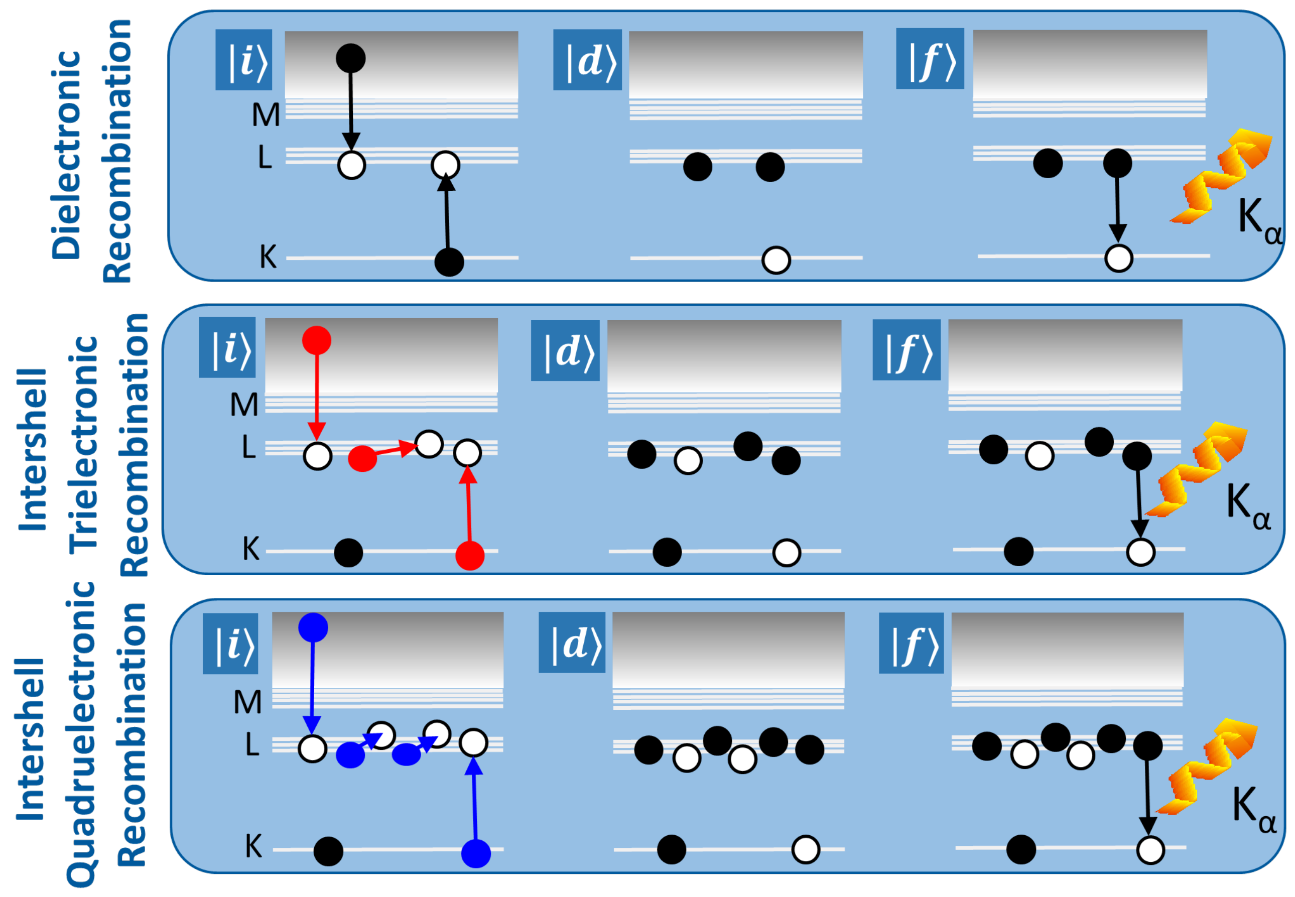
While investigating the DR process, one should be able to observe the influence of higher order recombination processes. Moreover, it has been shown [4,5] that during the DR process, intershell higher-order recombination processes can strongly contribute to electron–ion recombination [6], as well as polarization [7]. Here, the intershell trielectronic recombination (TR, Figure 1) and the intershell quadruelectronic recombination (QR, Figure 1) processes play crucial roles. These processes differ by the first step of recombination, but all are described by the time reversal of the Auger effect. Therefore, they are included within the model described by Equation (2), which was implemented in the calculations carried out with the use of the Flexible Atomic Code [8].
2. Experimental Methods and Theoretical Approach
The research presented here was conducted using a commercial Dresden EBIT-S [9,10] at Jagiellonian University. The trap was equipped with an X-ray detector (XFlash 5030, Bruker Co., Billerica, MA, USA), with a resolution of about 130 eV (FWHM at 5.9 keV), which was placed perpendicular to the electron–beam axis at a distance of about 30 mm from the trap center. The typical vacuum conditions in the trap were in the region of mbar. The presented research focused on the X-ray spectroscopy of the DR, TR, and QR in argon ions with a gas pressure at the level of about mbar. Here, data collection was performed with the use of the TERX system (Time and Energy Resolved X-ray Measurement). This system enables the registration of photon energy as a function of electron energy. The TERX system sorts and stores the detector data in the measurement matrix. This matrix is limited to the size of 1000 × 1000 channels. The minimal electron energy step in this scanning procedure was 1 eV. The resonant structures of the DR, TR, and QR in argon ions were investigated with TERX via scanning the electron energy in the range of 2100–2600 eV for K-LL DR and in the range of 2070–3500 eV for the higher shells’ DR processes. The collected X-ray spectra are presented in Figure 4 and Figure 5.
For the planning and explanation of the experimental results, the FAC calculations [8] were performed based on Equation (2) (presented in Figure 2 and Figure 3). For a deeper understanding of the X-ray spectra (shown in Figure 4), different DR processes (K-LL, K-LM, K-LO, and K-MM) were considered. As has been stressed, the radiative deexcitation always occurs as the second step of the DR. However, different deexcitation channels are possible. This is clearly seen when the K-LM DR process is discussed. In the second step of this particular DR process, , , and emissions are possible. In the presented experiment, the X-ray detector was separated from the inside of the EBIT with two m beryllium windows. Due to the absorption in beryllium, only the Ar K-lines were detected with sufficient efficiency. Therefore, only these deexcitation channels (, , and following) were available as a signature of the observed DR, TR, and QR processes in argon. These particular deexcitation channels are discussed below.
Summarizing the presented theoretical approach, it is worth emphasizing that the initial state of Ar was considered as the ground state (e.g., 1s2 for the He-like ion). In the EBIT plasma conditions, most ions are in this state. For intermediate states of Ar, all different electron configurations were considered for the KLn (e.g., 1s2lnl’ for the initial He-like ions), with n < 5, and additionally for the KMM. The deexcitation channels included possible Auger processes to different final states of Ar and all final radiative deexcitations to the Ar state. The FAC calculations included the broad set of different electron configurations with the full configuration interaction, as well as the mixing between the states.
3. Results and Discussion
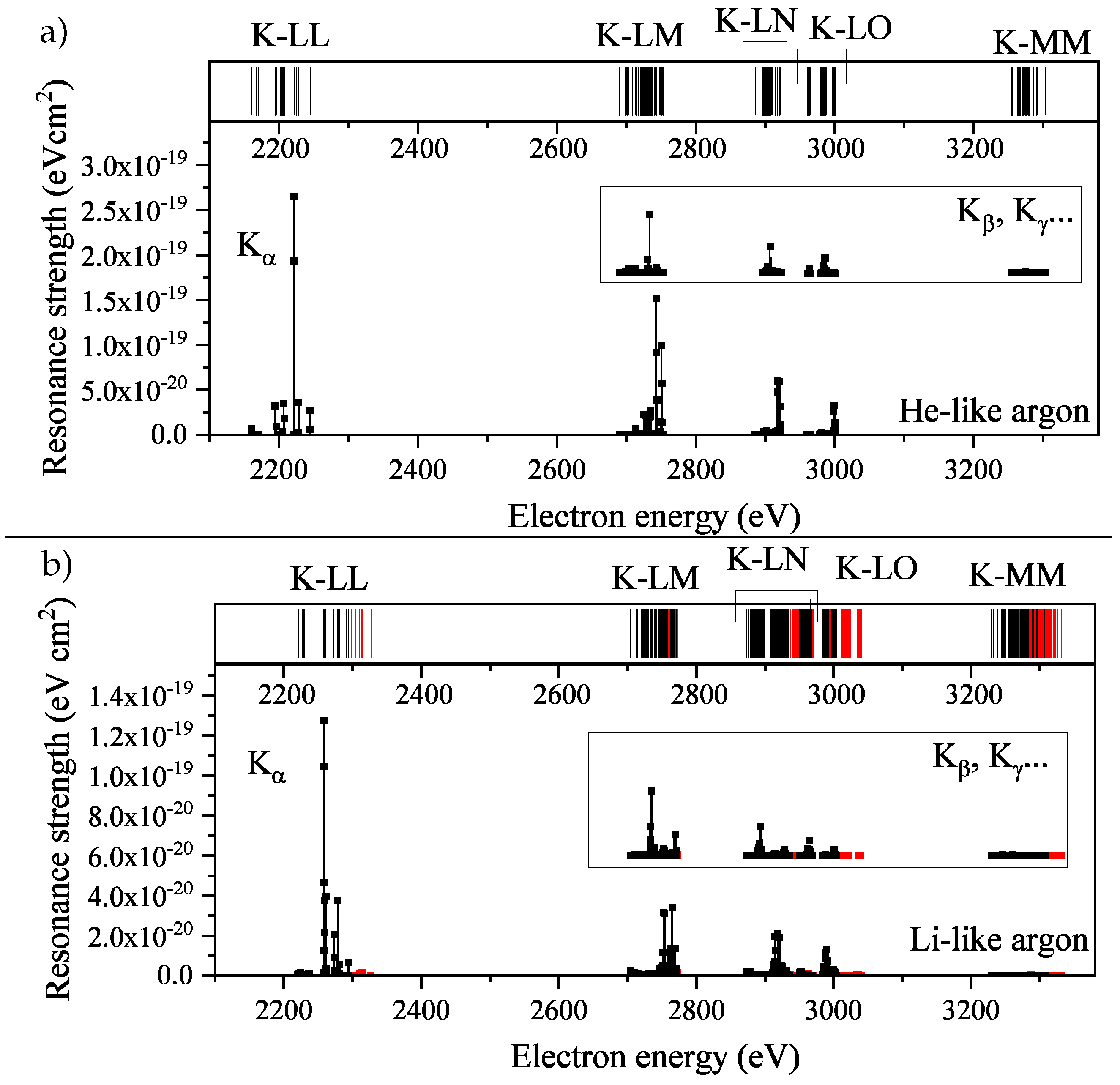
In Figure 2, we presented the results of the resonance strength calculations obtained for the He-like and Li-like argon ions. Here, one can see that for the electron energy range (2100–3400 eV), the signatures of many DR processes were present. These results point to the emission as the main deexcitation channel (see the graphs in Figure 2). The insets of Figure 2 showed the S for the resonances, which deexcited via the and emission. For the K-LL group, this radiation could not be produced. The scale of the results presented in these insets was the same as the scale in the main graph, which allowed the comparison of their strengths. In Figure 2, the TR processes were shown in red. For the He-like ions, the higher-order recombination processes were not possible, and for the Li-like ions the TR process was expected to give only a slight contribution to the spectra. The rugs at the top of the graphs in Figure 2 present the resonant electron energies of the different resonance groups and can be addressed as the resonance density. The analysis of results, presented there, showed a strong dependence of the positions of the K-LL resonance group on the ion charge state. Whereas, for the higher-shell resonances (K-LM, K-LN, K-LO, and K-MM) the groups’ positions were almost charge state independent.
To obtain a deeper understanding of the K-LL DR, additional calculations were performed for different ion charge states, which included particular resonance groups (K-LL DR, KL-LLL TR, and KLLL-LLLL QR in Figure 3). Here, only the was a possible deexcitation channel.
During data collection, the electron energy in EBIT was scanned in steps of 1 eV. Therefore, the resonance strength for all resonances was first sorted to the groups (DR, TR, and QR) and then added within the window of the 1 eV widths (compare Figure 2 and the two upper panels of Figure 3). This procedure enabled the presentation of the calculation results adequate to the experimental method chosen. As already mentioned, the resonant structure of K-LL DR is charge state dependent; therefore, the different charge states can be distinguished in the experimental data (presented in Figure 5). In Figure 3, it was also shown that for Ar, the KL-LLL TR was calculated to be stronger than the K-LL DR.
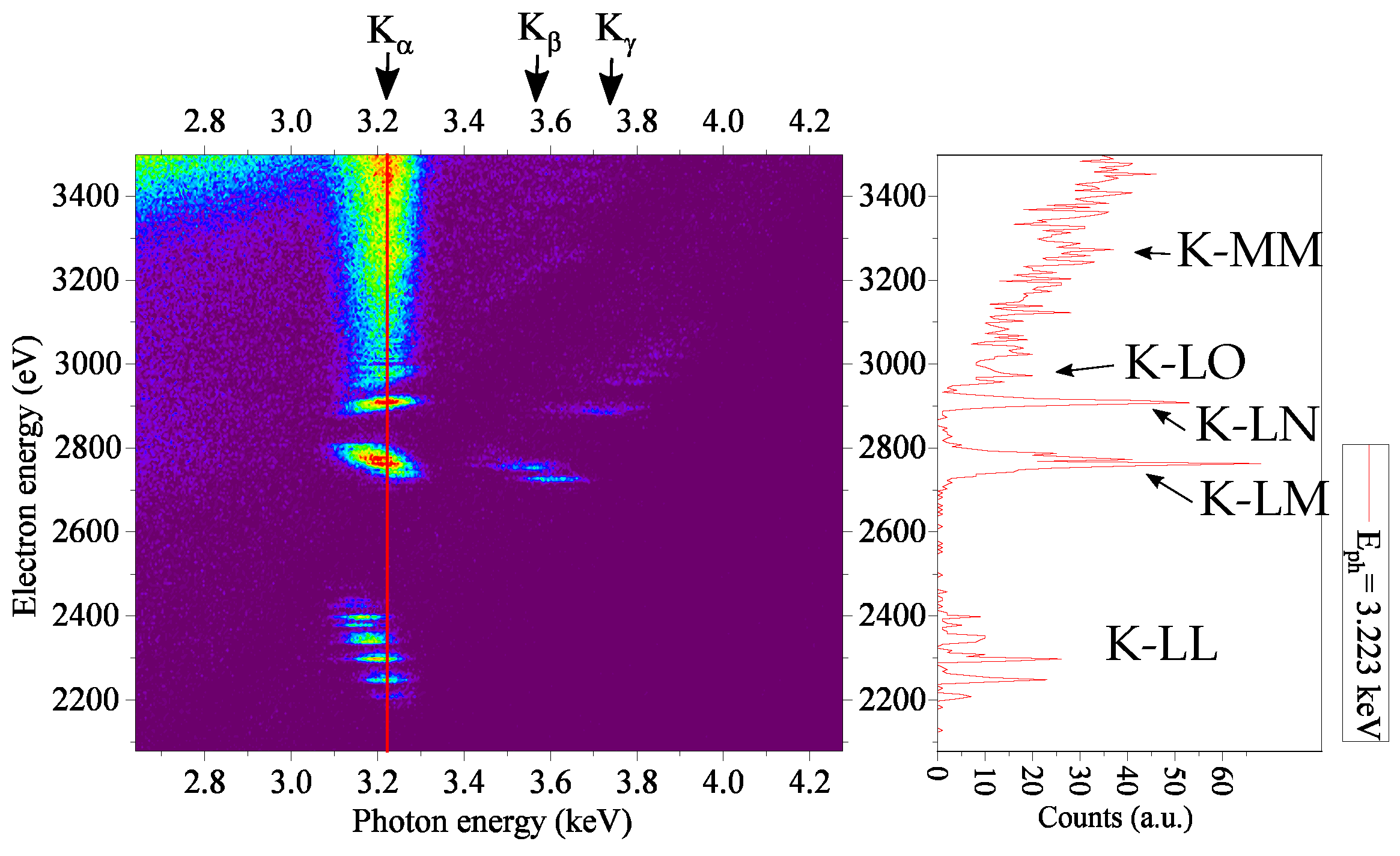
Figure 4 shows the spectrum collected with TERX for the electron energy scanned in the range of 2073–3502 eV. Due to the limitation in the TERX matrix size (1000 channels), the electron energy change step was 2 eV. In Figure 4, different deexcitation channels were clearly seen. The most intense was the radiation; however, the and radiation were also visible. The right panel of Figure 4 showed the rich structure of the DR processes for different electron energies. The processes were signed with the proper signatures based on the results of the calculations presented in Figure 2.
An important observation seen in Figure 4 was the change in the energy for different ion charge states. It was clearly seen for the K-LL DR structure around the electron energy of 2200–2400 eV. This provided confirmation that the EBIT plasma consisted of the different charge states of the ions.
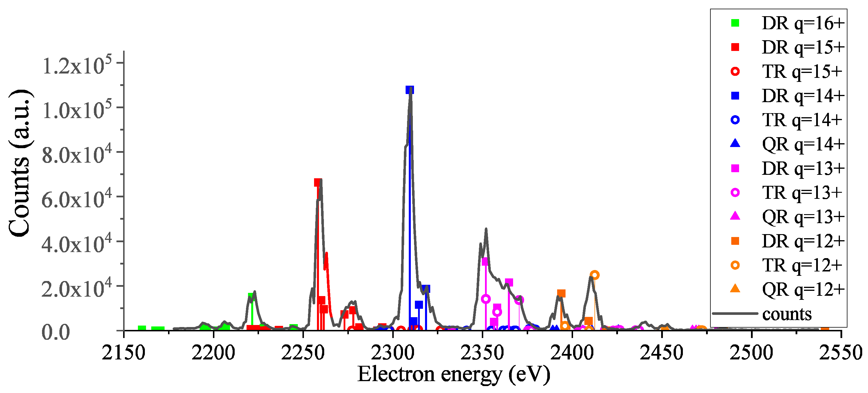
To have a better understanding of each K-LL DR structure (seen in Figure 4), an additional measurement was performed. The scanning of electron energy in the range of 2100–2600 eV enabled use of a minimal scanning step (1 eV). The projection of the collected intensity on the electron energy axis was presented in Figure 5. Here, the calculated resonance strength for the DR, TR, and QR (Figure 3) was also plotted on top of the experimental data. The resonance strength axis of each group of resonances calculated for the selected charge state was scaled with an appropriate factor so that the maximal resonance strength lay atop the experimental data resonant structure. Based on the scaling factors of the different charge state resonance groups, it was possible to draw conclusions about the charge state distribution. These are presented in Table 1.
Moreover, this way of presenting data enabled the identification of the charge state of the active ion. These data together with other measured ions will be used in a future publication to verify the DR Z-scaling laws ([11] and references therein). Moreover, in Figure 5, different processes were shown with different symbols: DR (square), TR (circle), and QR (triangle). An additional advantage of this data presentation is the possibility to easily compare the contribution of the DR, TR, and QR processes in the observed resonant structure. Therefore, based on Figure 5, we conclude that for Ar, Ar, Ar, Ar, the K-LL DR process strongly prevailed over the higher-order recombination processes. However, for Ar, the higher-order recombination processes, especially the TR, prevailed over the DR. For Ar, the double-structure radiation for around 2400 eV showed that the KL-LLL TR process was more intense than the K-LL DR. This observation was in agreement with the previous experimental results [3,6]. Moreover, for Ar, it was possible determine the TR/DR ratio. The results of the calculations presented in Figure 3 gave this ratio at the level of 1.49, whereas the experimental data delivered the value of 1.46 ± 0.06. This is compared with the experimental value of 1.43 ± 0.19 presented in [6]. We obtained a better resolution than previously reported [6]. However, we were not able to resolve the TR and DR contribution for other ion charge states (Figure 5).
4. Conclusions
The experimental data presented within this article showed the resonant structures of multielectron recombination processes in argon ions. While scanning the electron energy in EBIT, different DR processes were observed. Here, for the K-LM, K-LN, K-LO, and K-MM, the X-ray spectroscopy revealed resonant structures in different deexcitation channels (, , and radiation). For these processes, the resonant electron energies were almost charge state independent. Therefore, the structures of those resonances (presented Figure 4) could not be used to distinguish the active ion charge state. However, the resonant electron energy of the K-LL DR process differed much more strongly between the argon ion charge states. The resonant structures of the K-LL DR (Figure 5) allowed us to identify the active ion charge state. Moreover, the comparison of the experimental data and the results of the resonance strength calculations led to the conclusion that for Ar, the KL-LLL TR prevailed over the K-LL DR process. In Table 1, the estimated charge state distribution was presented. One should keep in mind that this distribution was an average for the whole electron energy range.
Author Contributions
Experimental results: W.B.-N. and A.W.; Theoretical analysis: W.B.-N., P.A. and F.G., Writing—original draft preparation, W.B.-N.; Writing—review and editing, all authors; supervision, A.W. All authors have read and agreed to the published version of the manuscript.
Funding
W.B.-N. acknowledges the GET_INvolved Programme at FAIR/GSI and the JIPhD program through contract POWR.03.05.00-00-Z309/17-00. F.G. acknowledges support from FCT (Portugal) through contract UI/BD/151000/2021.
Data Availability Statement
The data presented in this study are available on request from the corresponding author.
Conflicts of Interest
The authors declare no conflict of interest.
References
- Kallman, T.R.; Palmeri, P. Atomic data for X-ray astrophysics. Rev. Mod. Phys. 2007, 79, 79. [Google Scholar] [CrossRef] [Green Version]
- Baumann, T.M.; Harman, Z.; Stark, J.; Beilmann, C.; Liang, G.; Mokler, P.H.; Ullrich, J.; López-Urrutia, J.R.C. Contributions of dielectronic, trielectronic, and metastable channels to the resonant intershell recombination of highly charged silicon ions. Phys. Rev. A 2014, 90, 052704. [Google Scholar] [CrossRef]
- Beilmann, C.; Mokler, P.H.; Bernitt, S.; Keitel, C.H.; Ullrich, J.; López-Urrutia, J.C.; Harman, Z. Prominent higher-order contributions to electronic recombination. Phys. Rev. Lett. 2011, 107, 143201. [Google Scholar] [CrossRef] [PubMed]
- Schnell, M.; Gwinner, G.; Badnell, N.R.; Bannister, M.E.; Böhm, S.; Colgan, J.; Kieslich, S.; Loch, S.D.; Mitnik, D.; Müller, A.; et al. Observation of trielectronic recombination in Be-like Cl ions. Phys. Rev. Lett. 2003, 91, 043001. [Google Scholar] [CrossRef] [PubMed]
- Fogle, M.; Badnell, N.R.; Glans, P.; Loch, S.D.; Madzunkov, S.; Abdel-Naby, S.A.; Pindzola, M.S.; Schuch, R. Electron-ion recombination of Be-like C, N, and O. Astron. Astrophys. 2005, 442, 757–766. [Google Scholar] [CrossRef]
- Beilmann, C.; Harman, Z.; Mokler, P.H.; Bernitt, S.; Keitel, C.H.; Ullrich, J.; López-Urrutia, J.C. Major role of multielectronic K-L intershell resonant recombination processes in Li- to O-like ions of Ar, Fe, and Kr. Phys. Rev. A 2013, 88, 062706. [Google Scholar] [CrossRef] [Green Version]
- Shah, C.; Amaro, P.; Steinbrügge, R.; Beilmann, C.; Bernitt, S.; Fritzsche, S.; Surzhykov, A.; López-Urrutia, J.R.C.; Tashenov, S. Strong higher-order resonant contributions to X-ray line polarization in hot plasmas. Phys. Rev. E 2008, 93, 6. [Google Scholar] [CrossRef] [PubMed] [Green Version]
- Gu, M.F. The flexible atomic code. Can. J. Phys. 2008, 86, 5. [Google Scholar] [CrossRef]
- Irradiation Facility-S at Jagiellonian University Krakow. Available online: https://www.dreebit-ibt.com/reference/irradiation-facility-s-at-jagiellonian-university-krakow.html (accessed on 4 October 2022).
- Zschornack, G.; Schmidt, M.; Thorn, A. Electron Beam Ion Sources. CERN Yellow Rep. 2013, 7, 165–201. [Google Scholar]
- Herman, Z.; Shah, C.; Gonzalez Martinez, A.; Ulrich, D.; Tawara, H.; Keitel, C.; Ullrich, J.; Crespo López-Urrutia, J. Resonance strengths for KLL dielectronic recombination of highly charged mercury ions and improved empirical Z -scaling law. Phys. Rev. A 2019, 99, 1. [Google Scholar] [CrossRef]
Figure 1.
The two-step multielectron recombination processes for DR K-LL (top, black), TR KL-LLL (middle, red), and QR KLL-LLLL (bottom, blue).
Figure 1.
The two-step multielectron recombination processes for DR K-LL (top, black), TR KL-LLL (middle, red), and QR KLL-LLLL (bottom, blue).

Figure 2.
The results of the FAC calculation of the resonance strength (S) for resonances leading to K line emission for: (a) the DR processes in the He-like argon ions and (b) the DR (black) and TR (red) processes in the Li-like argon ions. The main graphs show the S for the deexcitation channel, whereas the insets present the S for the and deexcitation channels (same scale but with offset).

Figure 3.
The results of the FAC calculation of the resonance strength of the DR K-LL (black), TR KL-LLL (red), and QR KLL-LLLL (blue) for ions Ar-Ar. The results are added within the 1 eV window.
Figure 3.
The results of the FAC calculation of the resonance strength of the DR K-LL (black), TR KL-LLL (red), and QR KLL-LLLL (blue) for ions Ar-Ar. The results are added within the 1 eV window.
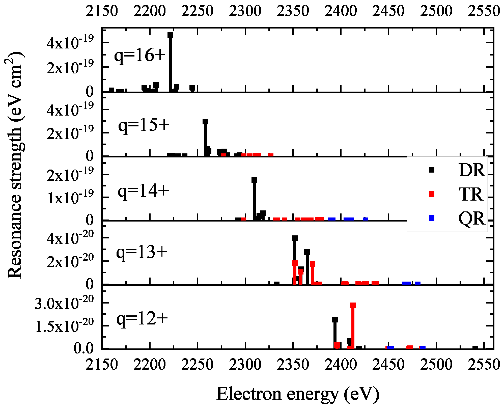
Figure 4.
The X-ray spectrum for the K-LL and K-LM radiation and higher-shell recombination processes, collected for electron energies in the range 2073–3503 eV. The measurement time was approx. 90 h. The right panel presents the counts collected for the selected photon energy = 3.223 keV ().
Figure 4.
The X-ray spectrum for the K-LL and K-LM radiation and higher-shell recombination processes, collected for electron energies in the range 2073–3503 eV. The measurement time was approx. 90 h. The right panel presents the counts collected for the selected photon energy = 3.223 keV ().

Figure 5.
The projection of the spectrum of the K-LL radiation structure on the electron energy axis. The measurement time was 241.5 h. The calculated resonance strength was plotted on the top of the experimental result. Each group of resonances calculated for the selected charge state was scaled with an appropriate factor to obtain an agreement, as shown in the plot. This allows for the identification of the charge state of the active ion.


Table 1.
The estimated charge state composition of the Ar EBIT plasma.
| Ar | Ar | Ar | Ar | Ar |
|---|---|---|---|---|
Disclaimer/Publisher’s Note: The statements, opinions and data contained in all publications are solely those of the individual author(s) and contributor(s) and not of MDPI and/or the editor(s). MDPI and/or the editor(s) disclaim responsibility for any injury to people or property resulting from any ideas, methods, instructions or products referred to in the content. |
© 2022 by the authors. Licensee MDPI, Basel, Switzerland. This article is an open access article distributed under the terms and conditions of the Creative Commons Attribution (CC BY) license (https://creativecommons.org/licenses/by/4.0/).
Share and Cite
MDPI and ACS Style
Biela-Nowaczyk, W.; Amaro, P.; Grilo, F.; Warczak, A., on behalf of the SPARC Collaboration. Higher-Order Recombination Processes in Argon Ions Observed via X-ray Emission in an EBIT. Atoms 2023, 11, 1. https://doi.org/10.3390/atoms11010001
AMA Style
Biela-Nowaczyk W, Amaro P, Grilo F, Warczak A on behalf of the SPARC Collaboration. Higher-Order Recombination Processes in Argon Ions Observed via X-ray Emission in an EBIT. Atoms. 2023; 11(1):1. https://doi.org/10.3390/atoms11010001
Chicago/Turabian StyleBiela-Nowaczyk, Weronika, Pedro Amaro, Filipe Grilo, and Andrzej Warczak on behalf of the SPARC Collaboration. 2023. "Higher-Order Recombination Processes in Argon Ions Observed via X-ray Emission in an EBIT" Atoms 11, no. 1: 1. https://doi.org/10.3390/atoms11010001
Note that from the first issue of 2016, this journal uses article numbers instead of page numbers. See further details here.