Article

Radio Frequency Interference Measurements to Determine the New Frequency Sub-Bands of the Coaxial L-P Cryogenic Receiver of the Sardinia Radio Telescope

National Institute for Astrophysics (INAF), Cagliari Astronomical Observatory, Via della Scienza 5, 09047 Selargius, Italy
*
Author to whom correspondence should be addressed.
Universe 2023, 9(9), 390; https://doi.org/10.3390/universe9090390
Submission received: 6 August 2023 / Revised: 20 August 2023 / Accepted: 27 August 2023 / Published: 28 August 2023

Abstract

:
Radio frequency interference (RFI) represents all unwanted signals detected by radio receivers of a telescope. Unfortunately, the presence of RFI is significantly increasing with the technological development of wireless systems around the world. For this reason, RFI measurement campaigns are periodically necessary to map the RFI scenario around a telescope. The Sardinia Radio Telescope (SRT) is an Italian instrument that was designed to operate in a wide frequency band between 300 MHz and 116 GHz. One of the receivers of the telescope is a coaxial cryogenic receiver that covered a portion of the P and L bands (i.e., 305–410 MHz and 1300–1800 MHz) in its original version. Although the receiver was used for years to observe bright sources with sufficient results, its sub-bands can be redesigned considering the most recently evolved RFI scenario. In this paper, the results of a RFI measurement campaign are reported and discussed. On the basis of these results, the new sub-bands of the L-P receiver, together with the design of the new microwave filter selector block of the SRT receiver, are presented. In this way, SRT will cover up to 120 MHz and 460 MHz of −3 dB bandwidth at the P-band (290–410 MHz) and L-band (1320–1780 MHz), respectively. The bands of these filters are selected to reject the main RFI with high levels of amplitude and optimize the estimated antenna temperature and sensitivity of the receiver during the research activities, such as pulsar observations, very long baseline interferometer applications and spectroscopy science.

1. Introduction

Radio frequency interference (RFI) consists of unwanted human-made signals detected by a receiver (i.e., radio telescope), such as self-produced spurious signals and harmonics from lower frequency bands, and spread-spectrum signals generated by devices installed in the surrounding area or on space-to-ground transmissions [1]. Currently, the presence of RFI is increasing because of the extensive abuse of wireless technologies around the world [2]. Although the International Telecommunication Union (ITU) assigned several specific frequency bands to the radio astronomy service (RAS) [3], the radio receivers for telescopes are designed and developed with the widest bandwidth as much as possible. In this manner, astronomers can analyze a larger amount of data at several frequencies with respect to the narrow bands dedicated to the RAS. In the receiver design stage, or more generally in a radio telescope development, a trade-off needs to be found in order to have a wide bandwidth with the least number of unwanted signals [4,5,6,7].
The unavoidable presence of RFI in the telescope frequency bands increases the estimated antenna temperature, leading to a degradation in the sensitivity of the system. Consequently, the monitoring and mitigation of RFI represents one of the most important aspects to consider for the optimal functioning of a radio telescope. With regards to the monitoring operations, dedicated measurement campaigns are periodically necessary [7,8,9]. Typically, the RFI survey can be performed using fixed stations, such as the telescope itself or a dedicated ad hoc system for RFI detection, and mobile laboratories [9]. Regarding the RFI mitigation, it can be carried out by interventions on the receiver hardware components or by developing dedicated software [8]. In the first option, the design of the signal acquisition chain can be revised by adding microwave filters with a focus on rejecting the unwanted signals with the highest levels of amplitude, which can saturate the active components (i.e., the low noise amplifiers) of the receiving chain [9,10]. In the case of the development of dedicated software for RFI mitigation, several works are available in the literature [11,12,13]. For instance, a specific algorithm for the spectrogram analysis using image processing techniques to detect and mitigate RFI by two-dimensional filtering is proposed in [12]. In addition, considering the antenna features and geographic and meteorological databases, the scenario around a telescope can be modelled to evaluate the influence of RFI and protect the radio environment in the surrounding area, as well as improving site selection for planned radio astronomical facilities [13].
Focusing on the ultra-high frequency (UHF) and in particular, on the so-called P-band (i.e., 200–1000 MHz) and L-band (i.e., 1–2 GHz), a portion of these bands is assigned to the RAS in Italy (Europe). In detail, for the P-band, the dedicated sub-band sweeps between 406.1 MHz and 410 MHz [3]. Instead, the range 1400–1427 MHz is reserved for the L-band [3]. Although the RAS bands are available, radio receivers are usually designed to operate at larger bandwidths in order to achieve better sensitivity [3]. Several scientific studies are performed thanks to data detected by radio telescopes at these frequencies (i.e., pulsar research, eclipsing binaries, observations for the very long baseline interferometer, etc. [14,15,16]). In addition, some radars are useful for space situational awareness (SSA) activities operating at the P-band [17,18,19].
In Italy, the Sardinia Radio Telescope (SRT), owned by the Italian National Institute for Astrophysics (INAF), is an instrument designed to operate over a wide frequency range between 300 MHz and 116 GHz. The telescope is located 35 km northeast of Cagliari, in the Pranu Sanguini territory (Lat. 39.493072° N–Long. 9.245151° E), at an altitude of about 650 m above sea level. The technical characteristics of the telescope and its radio receivers are described in detail in [9,20,21,22,23]. One of its radio receivers is the cryogenic coaxial dual-frequency L-P band receiver, which is installed on the primary focus and covers the nominal bands of 305–410 MHz and 1300–1800 MHz simultaneously. Although this receiver has been used for years with sufficient results in astronomy research, it presents some modules that could be improved in terms of performance and sensitivity. A detailed description of this receiver and a feasibility study of its upgrade are presented in [9].
In this paper, the methodology and results of a RFI measurements campaign at the P and L frequency bands is presented. The measurements are performed in the area around the SRT site by the end of 2022 and in early 2023. This RFI evaluation is focused on the larger bands (i.e., 250–450 MHz and 1200–1800 MHz) than the range cover by the L-P receiver of SRT. The aim is to redefine the sub-bands of this radio receiver in an attempt to reject the main unwanted signals with very high levels of amplitude that have arisen during the years of the telescope’s operation. In this regard, the bandwidths of new microwave filters to install on the upgraded version of the receiver are presented. The measurement setup is accurately described in Section 2. The results of the RFI measurements campaign and the bandwidths chosen for the new microwave filters are reported in Section 3. Finally, a discussion with the conclusions about the work is outlined in Section 4.

2. Materials and Methods

A RFI measurements campaign has been conducted using the INAF mobile laboratory by the end of 2022 and in early 2023 [24]. Two strategic geographic points are considered to perform the measurements. These points are situated at an altitude comparable with the position of the primary focus of SRT, where the L-P receiver is installed. A map of this scenario is shown in Figure 1a. In particular, the selected locations are:
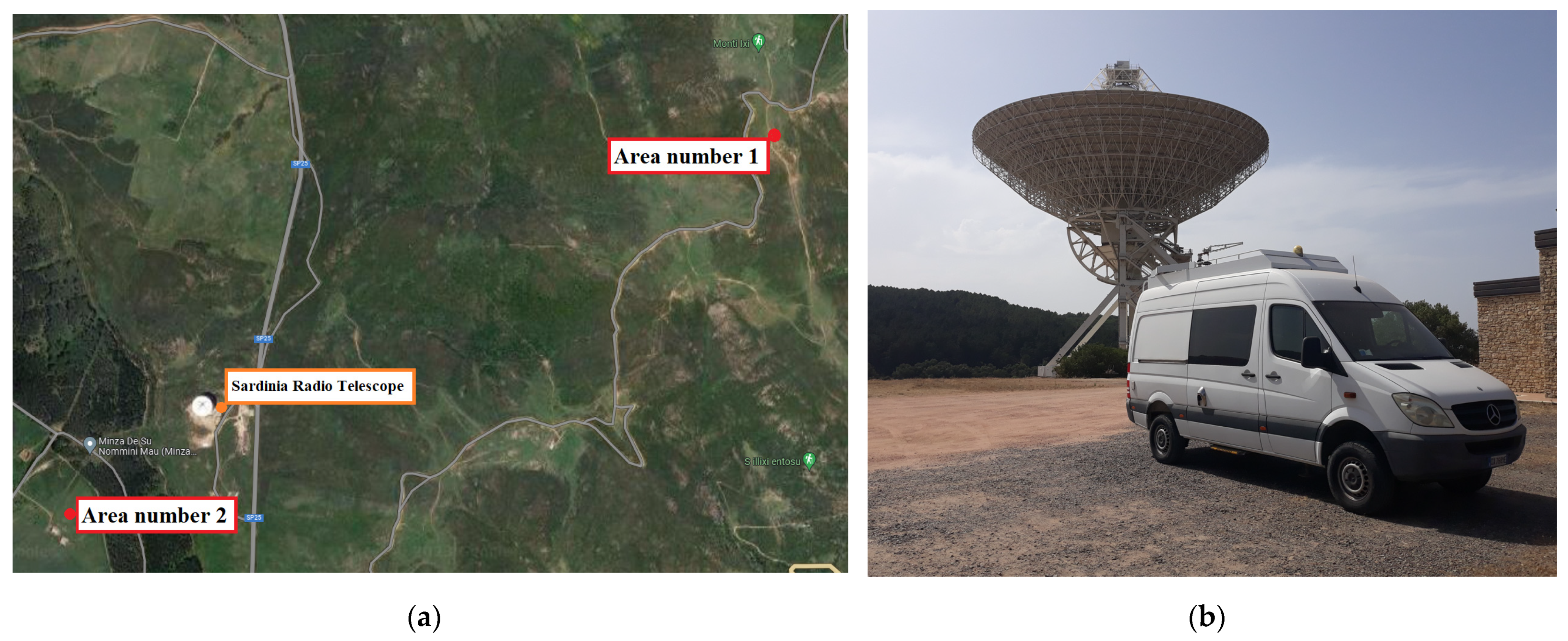
  • Area number 1: a point on the Monti Ixi mountain (Lat. 39.50075958202559° N–Long. 9.26616912945711° E), located at about 2 km from SRT;
  • Area number 2: a point on the Union of Municipalities of Gerrei, called Colonia Montana (Lat. 39.4900647290649° N–Long. 9.23939203600374° E), located at about 600 m from SRT.
The INAF mobile laboratory was designed to have a very high sensitivity and a large dynamic range over a wide frequency range up to 40 GHz [24]. A photo of the system is shown in Figure 1b. The system is equipped with a retractable telescopic mast where the antenna is installed, and can be electronically or manually rotated in the azimuthal direction. Six channels, composed of an ad hoc receiver chain of microwave components (i.e., microwave filters, low noise amplifier, etc.) are available to conduct measurements between 300 MHz and 18 GHz. For the frequency range above 18 GHz, a different configuration with two dedicated low noise amplifiers is used. A detailed characterization of all available channels is described in [24].
Regarding the RFI campaign proposed in this paper, channels A and B of the INAF mobile laboratory have been used. In detail, channel A is based on a band pass filter (BPF), model 8BC-360/A120-S from K&L, Salisbury, USA [25], which covers the band between 250 and 450 MHz. Instead, the channel B uses another BPF, model 8BC-1510/A590-S from K&L, Salisbury, USA [25], which sweeps in the range of 1200–1800 MHz. For each band, a commercial log periodic dipole antenna (LDPA) is used [24]. The specifications of the channels A and B and the two LDPAs are summarized in Table 1.
The back end of the system is based on a spectrum analyzer, model FSV40 from Rohde & Schwarz, Columbia, IN, USA [26]. The P-band and L-band scenario around the SRT site have been determined with a focus on impulsive and stationary signals. For this discrimination, the spectrum analyzer has been properly set and these settings are reported in the discussion about the results of Section 3.

3. Results and Discussion

The results of the RFI measurements campaign are separately presented for the P-band (Section 3.1) and the L-band (Section 3.2). The same measurement procedure has been applied for both of these bands. This procedure consists of some 360-degree slow rotations of the mast where the antenna is positioned. The total duration of this measurement procedure is up to 15 min, which is considered a sufficient timing window to map the general RFI scenario in the considered zone. The spectrum analyzer is set in “max hold” mode and the data are stored. This procedure has been repeated for each antenna’s linear polarization (i.e., horizontal and vertical) and the data are merged. In this way, all azimuthal directions are considered and the surrounding RFI scenario can be accurately mapped.
The measurement procedure has been used for both continuous and impulsive signal detection. The difference between these two modes consists of the resolution bandwidth (RBW) of the spectrum analyzer. In more detail, the RBW can be set to few kHz (i.e., 100 kHz) for detecting continuous signals, and from this aspect derives the name “narrowband campaign”. Whereas, the survey of impulsive signals requires a higher RBW, such as a few MHz (i.e., 1 MHz). For this reason, the measurement of impulsive signals are called a “wideband campaign”.
Naturally, a more accurate campaign could be performed to verify the possible presence of other episodic signals, depending on the time of the day/week/month. In this case, the timing acquisition window could be considerably larger, such as one or more days. However, for the goal of this paper, a 15 min timing acquisition window represents the best solution to achieve the desired result. In fact, the aim of these RFI measurements consists of designing the new filter selector block of the L-P receiver to detect (and reject using the new microwave filters) only the main unwanted signals present on a daily basis on the SRT observations. In general, all of the other signals, such as episodic signals, can be rejected by the astronomers using dedicated software for astronomic data analysis, without the need to add new microwave filters to the signal acquisition chain of the receiver.

3.1. The RFI Measurement Campaign at P-Band

Regarding the P-band, a critical point needs to be explained. As discovered in recent years, a signal with a very high level of amplitude spreads in the air. This signal sweeps in the frequency range between 385 and 395 MHz, and derives from the Terrestrial Trunked Radio (TETRA) system for the radio communications of the Italian Ministry of Defense. Previous results of a measurements campaign that detected and analyzed this signal are reported in [9]. Unfortunately, one of the many TETRA stations is installed on the Monte Ixi mountain, in a place very close to area number 1 of the measurement campaign presented in this paper. In order to prevent the saturation of the active components of the front end, a Notch filter (i.e., model 6PR6-392.5-X4.5 S11 from Reactel, Inc., Gaithersburg, MD, USA [27]) has been installed on the receiving chain of the INAF mobile laboratory. This filter guarantees an attenuation of approximately 70 dB in the band 385–395 MHz.
Regarding area number 1 of Figure 1a, the results of the narrowband campaign (continuous signals) are shown in Figure 2a, whereas Figure 2b displays the results of the wideband measurements (impulsive signals).
Regarding area number 2 in Figure 1a, the results of continuous and impulsive signal detection are shown in Figure 3a and Figure 3b, respectively.
The structure of the charts is the same for Figure 2 and Figure 3. On the x-axis, the frequency range, between 250 MHz and 450 MHz, is considered in the measurements. On the y-axis, the amplitude of the signals is indicated in decibels and is referred to as 1 milliwatt (i.e., dBm). This amplitude is the power level of the signals detected by the INAF mobile laboratory at the input of the spectrum analyzer, used as the back end in the signal acquisition chain.
In general, the same signals are equally detected in the two different areas. Firstly, with regard to the continuous signals (narrowband campaign), the most significant signals are listed in the following:
  • 275–285 MHz: signals generated by defense systems, such as the Italian Air Force [28];
  • 300–330 MHz: signals of radars from the Italian Air Force [28];
  • 360–380 MHz: signals generated by defense systems such as the Italian Air Force and other worldwide military communication systems (ground-based and space-based) [28,29]. In particular, this signal belongs to the downlink of the Mobile User Objective System (MUOS), a United States space force narrowband military communication satellite system [29];
  • 402–406 MHz: weather balloons that can also generate signals into the RAS band [28];
  • 420–450 MHz: signals feed by aeronautical services, amateur radiolocation and active satellite sensors [28].
Secondly, regarding the impulsive signals (wideband campaign), in both zones a signal propagating in almost all frequency bands (in particular, between 270 and 380 MHz) has been detected. This signal is generated by the electrical line whose cables are supported by electricity pylons installed on the ground, passing through the entire zone. These cables are all isolated through surge voltage arresters from the electricity pylon. These surge voltage arresters wear out and trap dirt over time, resulting in the generation of electrical discharges and consequently impulsive radio frequency signals in a completely random manner. In addition, these conditions can also occur in strong wind that causes the oscillation of the cables, which are not completely isolated from the pylon. Unfortunately, these signals will always be present under certain conditions and can disturb astronomical observations. The Italian electricity operator could periodically undertake maintenance on the entire electricity line by replacing the surge voltage arresters. In this manner, a cleaner spectrum can be guaranteed.
On the basis of these results, the room temperature filter selector block of the coaxial L-P cryogenic receiver of SRT needs to be re-designed. The original version of this filter selector block is carefully described in [9]. In the case of the P-band channel, two new combinations of microwave filters have been considered. The first one, proposed by the pulsar research group and for very long baseline interferometer applications, consists of a combination between a BPF with a −3 dB bandwidth of 290–410 MHz and a notch filter for the TETRA signal rejection (i.e., 385–395 MHz). The other filter, which is useful mainly for pulsar research applications, is a BPF with a −3 db bandwidth between 290 and 360 MHz. The microwave filter for space debris application remains the same original version of the L-P receiver [30]. The main features of the old and the new selected filters are summarized in Table 2.
SRT is part of the worldwide and European VLBI Network (EVN) and its performances are compatible with those of the other telescopes. In particular, the new microwave filters proposed in this paper have specifications and features (see Table 2) in line with the front ends of other telescopes implied in the EVN experiments [31]. With the new microwave filters (BPF + Notch filter of Table 2), SRT will offer up to 120 MHz of −3 dB bandwidth at the P-band (see Table 2), resulting in one of the worldwide telescopes with the largest range of frequencies. Globally, the SRT’s characteristics can be compared with the Robert C. Byrd Green Bank Telescope (GBT), located in Green Bank (Green Bank, WV, USA). It has a diameter of 100 m and features a −3 dB bandwidth of 105 MHz between 290 MHz and 395 MHz (i.e., the band channel 342 MHz of the receiver named Prime Focus 1) and a −3 dB bandwidth of 135 MHz in the range of 385–520 MHz (i.e., the band channel 450 MHz of the receiver named Prime Focus 1) [32]. Moreover, the Effelsberg 100-m Radio Telescope, located in Bad Münstereifel (Bad Münstereifel, Germany), can be considered as a benchmark for SRT at the European level. This German telescope covers a frequency range between 400 MHz and 405 MHz and the band of 300–900 MHz with its P740mm and P500mm receivers, respectively [33].
In addition to the −3 dB bandwidth, the −30 dB frequency response of each filter is considered to be an important requirement, as indicated in Table 2. The radio astronomy tools used by digital back ends integrate received signals, and can detect RFIs outside the −3 dB filter bandwidth. These RFI signals can assume comparable levels of amplitude with signals from astronomy sources detected in the filter bandwidth. For this reason, in contrast to engineering projects that take into account the −3 dB response, the edges of the frequency response of a microwave filter for radio astronomy applications is considered when the attenuation is at least 30 dB.
Finally, in Figure 4, a schematic of the new filter selector block for the upgraded L-P receiver is proposed. The chain is composed of a microwave switch that permits the selection of the optimal path with an ad hoc filter for the specific observation. After that, a further amplification stage is provided by a room temperature low noise amplifier.

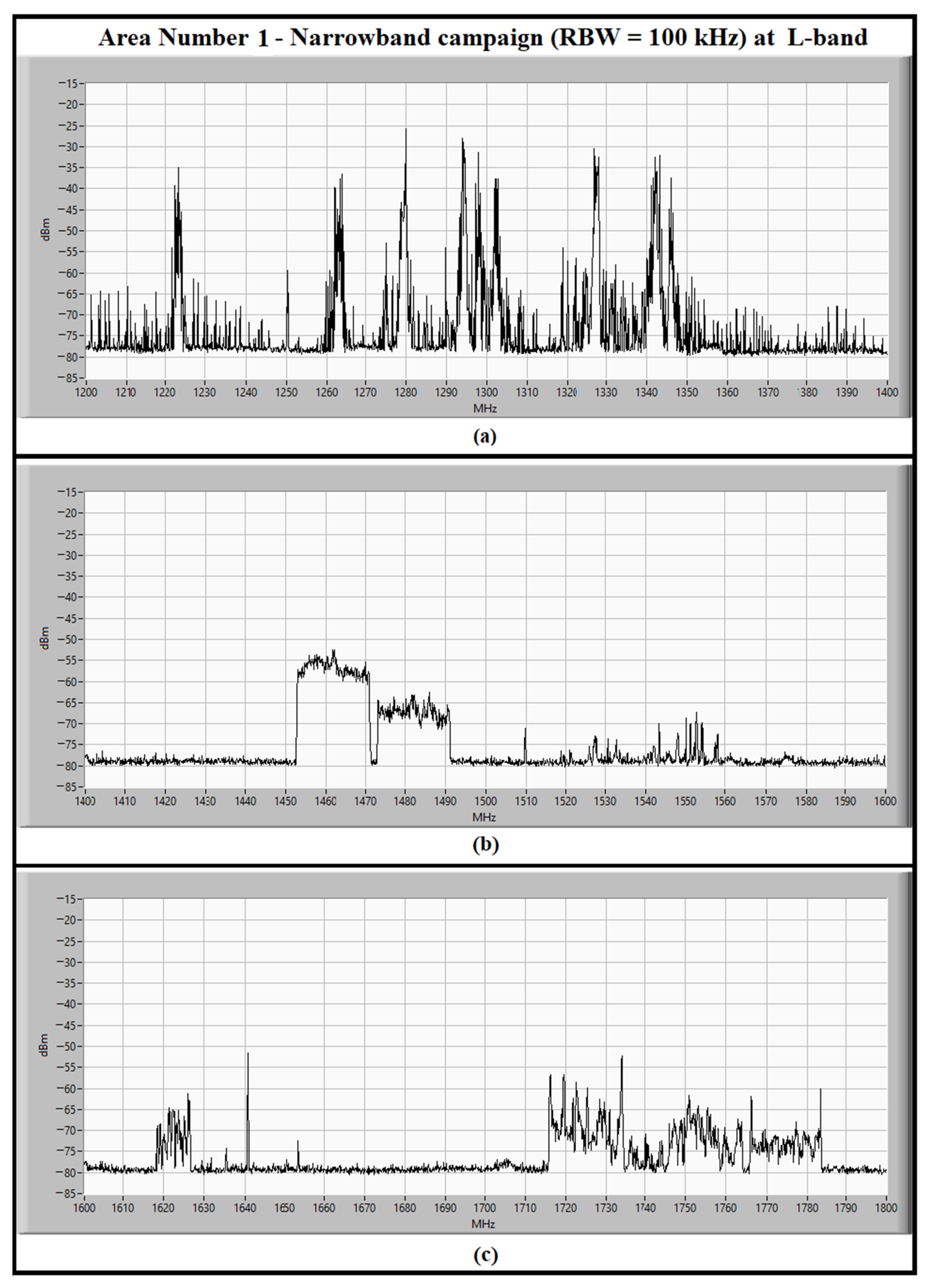
3.2. The RFI Measurement Campaign at L-Band

Since the portion of the L-band sweeps between 1200 MHz and 1800 MHz, the considered band has been divided into three parts of 200 MHz each. In this manner, the spectrum analyzer can be used with the same settings for the RBW for the P-band narrowband and wideband measurements.
The data measured during the narrowband campaign for the detection of continuous signals in area number 1 and area number 2 are shown in Figure 5 and Figure 6, respectively.
As well as for the P-band results, the structure of the charts for the L-band spectra is the same for Figure 5 and Figure 6. On the x-axis the frequency range is considered in the measurements, divided into three windows of 200 MHz between 1200 MHz and 1800 MHz. On the y-axis, the amplitude of the signals is indicated in decibels and referred to as 1 milliwatt (i.e., dBm). This amplitude is the power level of the signals detected by the INAF mobile laboratory at the input of the back end.
Analyzing the spectrum at L-band, several signals with high levels of amplitude have been found. The main ones are listed in the following:
  • 1200–1300 MHz: several signals derived from aeronautical and air force military radars, active sensors installed on civil and military satellites, GPS satellites, civil and military radio links are detected in this frequency range [28];
  • 1300–1350 MHz: signals generated by aeronautical radio navigation systems and several radio navigation satellites [28];
  • 1452–1492 MHz: signals of digital audio broadcasting (T-DAB) [28];
  • 1615–1630 MHz: radio communication links;
  • 1715–1785 MHz: signals from mobile communications [28,34].
Unfortunately, most of these permanent signals, such as the signals from military radars and civil mobile communications, did not exist when the coaxial L-P cryogenic receiver was designed. For this reason, the original bandwidth of the receiver was between 1300 and 1800 MHz. However, as time goes by, the presence of these unwanted signals will cause a narrowing of the entire useful band of observation.
The results of the wideband campaign for collecting impulsive signals are displayed in Figure 7 (i.e., Area number 1) and Figure 8 (i.e., area number 2). The structure of the graphs is the same as described above.
Concerning the impulsive signals, a high concentration of signals populates the sub-band 1200–1400 MHz (see Figure 7a and Figure 8a). In particular, these signals are spurious and harmonics of the military radars. An improvement could be achieved by adding ad hoc microwave filters to the transmitting systems in order to reject these unwanted signals.
Following discussions with the research groups that use the L-P receiver at L-band (i.e., pulsar and spectroscopy groups), the new sub-bands have been determined and the requirements for the new microwave filters are established. In particular, the L-band channel of the original version of the receiver was equipped with four radio frequency paths with different bands (see the first part of Table 3) [9]. For the upgraded version of the receiver, four new sub-bands have been selected for the new filters of the room temperature filter selector block. These filters will replace the old components. They are BPF with different −3 dB bandwidths, such as the bands 1320–1780 MHz and 1380–1780 MHz for pulsar applications, or the bands 1350–1550 MHz and 1530–1730 MHz for spectroscopy studies. The features of the new microwave filters are summarized in Table 3.
The largest −3 dB frequency band that SRT covers at the L-band, thanks to the installation of the new microwave filters proposed in this paper, is of 460 MHz between 1320 MHz and 1780 MHz (see Table 3). This filter rejects the continuous unwanted signals from the military radars and civil mobile communications. The new bandwidth at the L-band of SRT is in line with the GBT’s frequency range of 1150–1730 MHz, which is covered by its L-band receiver installed on its Gregorian focus [32]. Furthermore, the portion of the L-band covered by SRT is similar to the frequency range of the Effelsberg 100-m Radio Telescope at the European level. This instrument is equipped with two L-band receivers, named P217mm 7-beam and P200mm 4-box, which operate in the bands of 1270–1450 MHz and 1290–1430/1570–1720 MHz, respectively [33].
Finally, as well as for the P-band channel of the L-P receiver, a schematic of the new filter selector block is reported in Figure 9. The schematic is similar to that of the P-band channel. The difference lies in the filter models for each radio frequency path.

4. Conclusions and Future Work

One of the radio receivers of SRT covered a portion of the P-band, between 305 and 410 MHz, and the range of 1300–1800 MHz of the L-band. This is a coaxial dual-feed cryogenic receiver installed on the primary focus of the telescope. Although the receiver was used for years in its original design with good results, its sub-bands can be redesigned considering the most recently evolved RFI scenario. A dedicated RFI measurement campaign has been conducted to detect all continuous and impulsive signals at the P and L bands (i.e., 250–450 MHz and 1200–1800 MHz) in the telescope surrounding area. On the basis of the results of these measurements, the new sub-bands of the receiver have been established in accordance with the needs of the various research activities such as pulsars, very long baseline interferometer and spectroscopy applications. In particular, SRT will cover up to 120 MHz and 460 MHz of −3 dB bandwidth at the P-band (290–410 MHz) and L-band (1320–1780 MHz), respectively. These frequency sub-bands are the requirements of the new microwave filters to install in the coaxial L-P cryogenic receiver of SRT. Thanks to these new filters, the strong TETRA signals (at 385–395 MHz) and the strong signals from military radars and civil mobile communications (at 1200–1350 MHz) are rejected, avoiding the saturation of the active components of the receiving chain (i.e., low noise amplifiers) and the digital back end.
Recently, with the focus to maximize the scientific research results and extend them to high frequencies (up to 116 GHz) not yet covered by SRT, INAF has expressed an interest in upgrading its telescope. For these reasons, an Italian National Operational Program (PON) funding [35] has been allocated to INAF by the Italian Ministry of University and Research, with the aim to install four new receivers on the telescope at high frequencies, such as the Q-band (33–50 GHz) and W-band (70–116 GHz) [35,36]. The works relating to the PON project imposed the temporary dismantling of the old receivers, including the coaxial L-P cryogenic receiver, and a consequent stop on the SRT scientific observations. By taking advantage of this situation, it has been possible to study, upgrade, maintain, test and refurbishing the old receivers in the laboratory to verify their actual performances. In this context, the changes in the L-P receiver and the upgrade of its filter selector block, based on the design proposed in this paper, will be undertaken in the near future.

Author Contributions

Conceptualization, L.S., A.L. and F.G.; methodology, F.G. and L.S.; software, F.G.; validation, L.S., A.L. and F.G.; formal analysis, F.G.; investigation, L.S. and F.G.; resources, L.S., A.L. and F.G.; data curation, L.S. and F.G.; writing—original draft preparation, L.S.; writing—review and editing, L.S.; visualization, L.S., A.L. and F.G.; supervision, A.L.; project administration, L.S., A.L. and F.G.; funding acquisition, A.L. All authors have read and agreed to the published version of the manuscript.

Funding

This research received no external funding.

Data Availability Statement

Not applicable.

Acknowledgments

The authors are grateful to the astronomers of the Cagliari Astronomical Observatory for their invaluable suggestions about choosing the filters bands.

Conflicts of Interest

The authors declare no conflict of interest.

References

  1. Emery, W.; Campus, A. Chapter 4—Microwave Radiometry. In Introduction to Satellite Remote Sensing: Atmosphere, Ocean, Cryosphere and Land Applications; Elsevier: Amsterdam, The Netherlands, 2017; pp. 131–290. [Google Scholar]
  2. Querol, J.; Perez, A.; Camps, A. A Review of RFI Mitigation Techniques in Microwave Radiometry. Remote Sens. 2019, 11, 3042. [Google Scholar] [CrossRef]
  3. Cohen, J.; Spoelstra, T.; Amborsini, R.; van Driel, W. CRAF Handbook for Radio Astronomy, 3rd ed.; European Science Foundation: Strasbourg, France, 2005; pp. 141–145. [Google Scholar]
  4. Abidin, Z.Z.; Adnan, S.; Ibrahim, Z.A. RFI profiles of prime candidate sites for the first radio astronomical telescope in Malaysia. New Astron. 2010, 15, 307–312. [Google Scholar] [CrossRef]
  5. Prayag, V.; Beeharry, G.K.; Vydelingum, N.; Inggs, M. RFI in Mauritius. In Proceedings of the 2016 Radio Frequency Interference (RFI), Socorro, NM, USA, 17–20 October 2016. [Google Scholar] [CrossRef]
  6. Sitompul, P.P.; Manik, T.; Batubara, M.; Suhandi, B. Radio Frequency Interference Measurements for a Radio Astronomy Observatory Site in Indonesia. Aerospace 2021, 8, 51. [Google Scholar] [CrossRef]
  7. Peng, B.; Sun, J.M.; Zhang, H.I.; Piao, T.Y.; Li, J.Q.; Lei, L.; Luo, T.; Li, D.H.; Zheng, Y.J.; Nan, R. RFI test observations at a candidate SKA site in China. Exp. Astron. 2004, 17, 423–430. [Google Scholar] [CrossRef]
  8. Ford, J.M.; Buch, K.D. RFI mitigation techniques in radio astronomy. In Proceedings of the 2014 IEEE Geoscience and Remote Sensing Symposium, Quebec City, QC, Canada, 13–18 July 2014. [Google Scholar] [CrossRef]
  9. Ladu, A.; Schirru, L.; Gaudiomonte, F.; Marongiu, P.; Angius, G.; Perini, F.; Vargiu, G.P. Upgrading of the L-P Band Cryogenic Receiver of the Sardinia Radio Telescope: A Feasibility Study. Sensors 2022, 22, 4261. [Google Scholar] [CrossRef]
  10. Khan, I.; Raut, A.; Sureshkumar, S. Design of Switchable Hairpin Band Pass Filters for Low Frequency Radio Astronomy 2019. In Proceedings of the IEEE MTT-S International Microwave and RF Conference (IMARC), Mumbai, India, 13–15 December 2019. [Google Scholar] [CrossRef]
  11. Tarongi, J.M.; Camps, A. Radio Frequency Interference Detection and Mitigation Algorithms Based on Spectrogram Analysis. Algorithms 2011, 4, 239–261. [Google Scholar] [CrossRef]
  12. Wang, Y.; Zhang, H.; Wang, J.; Huang, S.; Hu, H.; Yang, C. A Software for RFI Analysis of Radio Environment around Radio Telescope. Universe 2023, 9, 277. [Google Scholar] [CrossRef]
  13. Baan, W.A. Implementing RFI mitigation in radio science. J. Astron. Instrum. 2019, 8, 1940010. [Google Scholar] [CrossRef]
  14. Perrodin, D.; Burgay, M.; Corongiu, A.; Pilia, M.; Possenti, A.; Iacolina, M.N.; Egron, E.; Ridolfi, A.; Tiburzi, C.; Casu, S.; et al. Pulsar science at the Sardinia radio telescope. In Proceedings of the International Astronomical Union, Macclesfield, UK, 4–8 September 2017. [Google Scholar]
  15. Egron, E.; Pellizzoni, A.; Giroletti, M.; Righini, S.; Stagni, M.; Orlati, A.; Migoni, C. Single-dish and VLBI observations of CygnusX-3 during the 2016 giant flare episode. Mon. Not. Roy. Astron. Soc. 2017, 471, 2703–2714. [Google Scholar] [CrossRef]
  16. Pilia, M.; Burgay, M.A.; Possenti, A.N.; Ridolfi, A.L.; Gajjar, V.; Corongiu, A.L.; Perrodin, D.E.; Bernardi, G.I.; Naldi, G.; Pupillo, G.; et al. The lowest-frequency fast radio bursts: Sardinia radio telescope detection of the periodic FRB 180,916 at 328 MHz. Astrophys. J. 2020, 896, L40. [Google Scholar] [CrossRef]
  17. Schirru, L.; Pisanu, T.; Podda, A. The Ad Hoc Back-End of the BIRALET Radar to Measure Slant-Range and Doppler Shift of Resident Space Objects. Electronics 2021, 10, 577. [Google Scholar] [CrossRef]
  18. Schirru, L.; Pisanu, T.; Navarrini, A.; Urru, E.; Gaudiomonte, F.; Ortu, P.; Montisci, G. Advantages of Using a C-band Phased Array Feed as a Receiver in the Sardinia Radio Telescope for Space Debris Monitoring. In Proceedings of the 2019 IEEE 2nd Ukraine Conference on Electrical and Computer Engineering (UKRCON), Lviv, Ukraine, 2–6 July 2019. [Google Scholar] [CrossRef]
  19. Losacco, M.; Di Lizia, P.; Massari, M.; Naldi, G.; Pupillo, G.; Bianchi, G.; Siminski, J. Initial orbit determination with the multibeam radar sensor BIRALES. Acta Astronaut. 2020, 167, 374–390. [Google Scholar] [CrossRef]
  20. Prandoni, I.; Murgia, M.; Tarchi, A.; Burgay, M.; Castangia, P.; Egron, E.; Govoni, F.; Pellizzoni, A.; Ricci, R.; Righini, S.; et al. The Sardinia Radio Telescope, From a technological project to a radio observatory. Astron. Astrophys. 2017, 608, 26. [Google Scholar] [CrossRef]
  21. Bolli, P.; Beltrán, M.; Burgay, M.; Contavalle, C.; Marongiu, P.; Orfei, A.; Pisanu, T.; Stanghellini, C.; Tingay, S.J.; Zacchiroli, G.; et al. A Review of Front-End Receivers for the INAF Radio Telescopes. In Proceedings of the Second URSI Atlantic Radio Science Meeting, Gran Canaria, Spain, 28 May–1 June 2018. [Google Scholar] [CrossRef]
  22. Peverini, O.A.; Tascone, R.; Virone, G.; Addamo, G.; Olivieri, A.; Orta, R. C-band dual-polarization receiver for the Sardinia Radio-Telescope. In Proceedings of the 2009 International Conference on Electromagnetics in Advanced Applications, Turin, Italy, 14–18 September 2009. [Google Scholar] [CrossRef]
  23. Orfei, A.; Carbonaro, L.; Cattani, A.; Cremonini, A.; Cresci, L.; Fiocchi, F.; Maccaferri, A.; Maccaferri, G.; Mariotti, S.; Monari, J.; et al. A Multi-Feed Receiver in the 18 to 26.5 GHz Band for Radio Astronomy. IEEE Antennas Propag. Mag. 2010, 52, 62–72. [Google Scholar] [CrossRef]
  24. Bolli, P.; Gaudiomonte, F.; Ambrosini, R.; Bortolotti, C.; Roma, M.; Barberi, C.; Piccoli, F. The mobile laboratory for radio-frequency interference monitoring at the Sardinia radio telescope. IEEE Antennas Propag. Mag. 2013, 55, 19–24. [Google Scholar] [CrossRef]
  25. K & L Microwave. Available online: https://www.klmicrowave.com/ (accessed on 31 July 2023).
  26. Rohde & Schwarz: FSV Signal and Spectrum Analyser. Available online: https://www.rohde-schwarz.com/us/products/test-and-measurement/signal-and-spectrum-analyzers/rs-fsv-signal-and-spectrum-analyzer_63493-10098.html?change_c=true (accessed on 31 July 2023).
  27. Reactel, Inc. Available online: https://reactel.com/ (accessed on 31 July 2023).
  28. The European Table of Frequency Allocations and Applications in the Frequency Range 8.3 kHz to 3000 GHz (ECA TABLE). Available online: https://docdb.cept.org/download/4316 (accessed on 31 July 2023).
  29. Oetting, J.D.; Jen, T. The Mobile User Objective System. Available online: https://secwww.jhuapl.edu/techdigest/Content/techdigest/pdf/V30-N02/30-02-Oetting.pdf (accessed on 31 July 2023).
  30. Pisanu, T.; Muntoni, G.; Schirru, L.; Ortu, P.; Urru, E.; Montisci, G. Recent Advances of the BIRALET System about Space Debris Detection. Aerospace 2021, 8, 86. [Google Scholar] [CrossRef]
  31. European VLBI Network. Capabilities—Frequency Coverage and Real-Time (e-EVN) Capabilities. Available online: https://www.evlbi.org/capabilities (accessed on 18 August 2023).
  32. Green Bank Observatory Website. GBT Receivers & Frequency Ranges. Available online: https://greenbankobservatory.org/science/gbt-observers/gbt-receivers-and-frequency-ranges/ (accessed on 18 August 2023).
  33. Effelsberg 100 m Teleskop—Receivers for the Effelsberg 100-m Telescope. Available online: https://eff100mwiki.mpifr-bonn.mpg.de/doku.php?id=information_for_astronomers:rx_list (accessed on 18 August 2023).
  34. Fanti, A.; Schirru, L.; Casu, S.; Lodi, M.B.; Riccio, G.; Mazzarella, G. Improvement and Testing of Models for Field Level Evaluation in Urban Environment. IEEE Trans. Antennas Propag. 2020, 68, 4038–4047. [Google Scholar] [CrossRef]
  35. Govoni, F.; Bolli, P.; Buffa, F.; Caito, L.; Carretti, E.; Comoretto, G.; Fierro, D.; Melis, A.; Murgia, M.; Navarrini, A.; et al. The high-frequency upgrade of the Sardinia Radio Telescope. In Proceedings of the 2021 XXXIVth General Assembly and Scientific Symposium of the International Union of Radio Science (URSI GASS), Rome, Italy, 28 August–4 September 2021. [Google Scholar] [CrossRef]
  36. Navarrini, A.; Olmi, L.; Nesti, R.; Ortu, P.; Marongiu, P.; Orlati, A.; Scalambra, A.; Orfei, A.; Roda, J.; Cattani, A.; et al. Feasibility Study of a W-Band Multibeam Heterodyne Receiver for the Gregorian Focus of the Sardinia Radio Telescope. IEEE Access 2022, 10, 26369–26403. [Google Scholar] [CrossRef]
Figure 1. (a) Map of the measurement campaign scenario. Area number 1 and Area number 2 are situated at an altitude comparable with the position of the primary focus of SRT, and represent the optimal points to perform the measurements; (b) photo of the INAF mobile laboratory with the Sardinia Radio Telescope in the background.
Universe 09 00390 g001
Figure 2. (a) The P-band spectrum, between 250 and 450 MHz, measured in the narrowband campaign (i.e., spectrum analyzer RBW set to 100 kHz) for detection of continuous signals in area number 1; (b) the P-band spectrum, between 250 and 450 MHz, measured in the wideband campaign (i.e., RBW set to 1 MHz) for detection of impulsive signals in area number 1.
Universe 09 00390 g002
Figure 3. (a) The P-band spectrum, between 250 and 450 MHz, measured in the narrowband campaign (i.e., spectrum analyzer RBW set to 100 kHz) for detection of continuous signals in area number 2; (b) The P-band spectrum, between 250 and 450 MHz, measured in the wideband campaign (i.e., RBW set to 1 MHz) for detection of impulsive signals in area number 2.
Universe 09 00390 g003
Figure 4. Schematic of the new room temperature P-band filter selector block of the upgraded L-P receiver.
Universe 09 00390 g004
Figure 5. The L-band spectrum, between 1200 and 1800 MHz, measured in the narrowband campaign (i.e., RBW set to 100 kHz) for detection of continuous signals in area number 1. The spectrum has been divided in three sub-bands. each of them of 200 MHz: (a) the sub-band between 1200 and 1400 MHz; (b) the sub-band between 1400 and 1600 MHz; (c) the sub-band between 1600 and 1800 MHz.
Universe 09 00390 g005
Figure 6. The L-band spectrum, between 1200 and 1800 MHz, measured in the narrowband campaign (i.e., RBW set to 100 kHz) for detection of impulsive signals in area number 2. The spectrum has been divided in three sub-bands, each of them of 200 MHz: (a) the sub-band between 1200 and 1400 MHz; (b) the sub-band between 1400 and 1600 MHz; (c) the sub-band between 1600 and 1800 MHz.
Universe 09 00390 g006
Figure 7. The L-band spectrum, between 1200 and 1800 MHz, measured in the wideband campaign (i.e., RBW set to 1 MHz) for detection of impulsive signals in area number 1. The spectrum has been divided in three sub-bands, each of them of 200 MHz: (a) the sub-band between 1200 and 1400 MHz; (b) the sub-band between 1400 and 1600 MHz; (c) the sub-band between 1600 and 1800 MHz.
Universe 09 00390 g007
Figure 8. The L-band spectrum, between 1200 and 1800 MHz, measured in the wideband campaign (i.e., RBW set to 1 MHz) for detection of impulsive signals in area number 2. The spectrum has been divided in three sub-bands, each of them of 200 MHz: (a) the sub-band between 1200 and 1400 MHz; (b) the sub-band between 1400 and 1600 MHz; (c) the sub-band between 1600 and 1800 MHz.
Universe 09 00390 g008
Figure 9. Schematic of the new room temperature of the L-band filter selector block of the upgraded L-P receiver.
Universe 09 00390 g009
Table 1. Specifications of the two front ends of the INAF mobile laboratory used for the P and L band RFI measurements.
NoteNameFrequency Coverage
[GHz]
Gain in Band
[dB/dBi]
Channel specificationsChannel A0.25–0.4536.5–35
Channel B1.2–1.831–28
Antenna specificationsP-band LPDA, model LPA 370–100.25–0.4511–12
L/S-band LPDA, model LPA 2000–10 1.2–3.311–11.5
Table 2. Specifications of the P-band microwave filters installed on the original version of the receiver and the new filters features for the upgraded system.
NoteType of Filter−3 dB Bandwidth−30 dB Bandwidth
P-band microwave filters installed on the original version of the L-P receiverBPF, model 5B340-357.5/T120-O/O
from K&L, Salisbury, MD, USA [25]
295–420 MHz 250–460 MHz
BPF, model 5B340-330/T5O-O/O
from K&L, Salisbury, MD, USA [25]
300–360 MHz 270–380 MHz
BPF, model 3B110-410/T15-O/O
from K&L, Salisbury, MD, USA [25]
402–418 MHz 380–440 MHz
New P-band microwave filters for the upgrade of the L-P receiverNo filter–extragalactic applications250–460 MHz250–460 MHz
BPF + Notch filter–Pulsar and VLBI290–410 MHz +
380–400 MHz
270–430 MHz +
385–395 MHz
BPF–Pulsar 290–360 MHz270–380 MHz
BPF–Space debris, model 3B110-410/T15-O/O
from K&L, Salisbury, MD, USA [25]
402–418 MHz 380–440 MHz
Table 3. Specifications of the L-band microwave filters installed on the original version of the receiver and the new filters features for the upgraded system.
NoteType of Filter−3 dB Bandwidth−30 dB Bandwidth
L-band microwave filters installed on the original version of the L-P receiverBPF, model 5B120-1540/T520-O/O from K&L, Salisbury, MD, USA [25]1250–1820 MHz1000–2000 MHz
BPF, model 5B120-1400/T120-O/O from K&L, Salisbury, MD, USA [25]1340–1460 MHz1250–1520 MHz
BPF, model 5B120-1655/T120-O/O from K&L, Salisbury, MD, USA [25]1600–1730 MHz1500–1850 MHz
Notch filter + BPF + Notch filter, models 6N45-1320/E62.7-O/O from K&L, Salisbury, MD, USA [25] +
5B120-1540/T520-O/O from
K&L, Salisbury, MD, USA [25] +
6NS11-1880/E138-O/O from K&L, Salisbury, MD, USA [25]
1310–1340 MHz +
1250–1820 MHz +
1790–1960 MHz
-
New L-band microwave filters for the upgrade of the L-P receiverBPF–Pulsar 1320–1780 MHz1300–1800 MHz
BPF–Pulsar and VLBI1380–1780 MHz1360–1800 MHz
BPF–Spectroscopy1350–1550 MHz-
BPF–Spectroscopy 1530–1730 MHz-
Disclaimer/Publisher’s Note: The statements, opinions and data contained in all publications are solely those of the individual author(s) and contributor(s) and not of MDPI and/or the editor(s). MDPI and/or the editor(s) disclaim responsibility for any injury to people or property resulting from any ideas, methods, instructions or products referred to in the content.

