Abstract
We aim to search for axion-like particles in the eV mass range using a variable-angle stimulated resonance photon collider (SRPC) with three intense laser beams. By changing angle of incidence of the three beams, the center-of-mass-system collision energy can be varied and the eV mass range can be continuously searched for. In this paper, we present the design and construction of such a variable-angle three-beam SRPC (), the verification of the variable-angle mechanism using a calibration laser, and realistic sensitivity projections for searches in the near future.
1. Introduction
Some of the unsolved problems of the Standard Model may be answered by new particles in the low-mass region, which have not yet been fully explored. Nambu–Goldstone bosons (NGBs), which are supposed to be ideally massless, may appear whenever global continuous symmetries spontaneously break [1,2,3]. Axions [4,5] are a representative candidate for such new fields in the low-mass range because an axion is a pseudo Nambu–Goldstone boson (pNGB) arising from spontaneous breaking of the Peccei–Quinn symmetry [6] introduced to solve the strong CP problem [7] in the context of Quantum ChromoDynamics (QCD). Moreover, if an axion weakly couples with matter fields, it can be a natural candidate for dark matter in the Universe [8,9,10]. More generalized low-mass particles are called Axion-Like-Particles (ALPs), some of which can also be reasonable dark matter candidates.
Many experiments have been conducted to detect ALPs focusing on their coupling to photons given by the following interaction Lagrangian , where a is an ALP field, is the electric field strength, is its dual, and is the coupling constant with dimensionless parameter g and M denoting an energy scale at which a symmetry breaking takes place. From the experimental point of view, a mass range between 0.001 and 10 eV has not been intensively explored, especially by laboratory-based experiments. In addition to the QCD axion scenario, a model miracle predicts the existence of an ALP in the mass range 0.01∼1 eV as a possible explanation for both inflation and dark matter [11,12]. It is thus very intriguing to conduct search experiments using laser fields in the near-infrared region in order to have sensitivities to the eV range.
We have been performing the ALP search based on the concept of Stimulated Resonant Photon Collider (SRPC) [13,14,15]. In this method, a single pulsed creation laser is focused and two arbitrary photons included in the field collide with each other, resulting in the production of an ALP and another pulsed inducing laser simultaneously stimulates its decay. This method does not require any assumptions except the interaction Lagrangian, and is thus independent of any cosmological and astrophysical models. In our previous study of a quasi-parallel collision system, we focused two lasers into the same optical axis and collided them at a shallow incident angle to search for ALPs in the sub-eV mass range [15,16,17,18,19]. Recently, we have proposed and demonstrated a pilot search for heavier ALPs based on a three-beam stimulated resonant collider () [20,21]. In the near future, we plan to search for ALPs by continuously changing collision angles in the eV mass range.
In this paper, we present the design and construction of a three-beam SRPC that can continuously scan the eV mass range by changing the incident angles of the three colliding lasers. We then show the verification of the mechanism of collision angle changes for individual mass range using a He:Neon laser for the calibration purpose. In the following sections, we first discuss a choice of the basic design to introduce the variable collision angles. Secondly, we introduce the concrete design for the variable-angle stimulated resonant photon collider by taking several aspects of calibration steps into account. Thirdly, we provide the verification of the selected mechanism using the calibration laser. We finally discuss the achievable sensitivity projections based on a realistic experimental parameter set and conclude the paper.
2. Kinematics in Three-Beam Stimulated Resonant Photon Collider,
Figure 1 shows the conceptual drawing of the . We consider a case that two creation laser pulses (green) are focused at the same incident angle with the same energy and similarly an inducing laser pulse (red) is focused with the energy which increases the interaction rate of stimulated scattering emitting signal photons of energy (blue) that satisfies energy-momentum conservation. Energy-momentum conservation between three-beam photons and a signal photon requires the following kinematical relations:
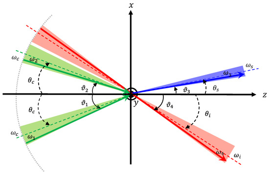
Figure 1.
Concept of a three-beam stimulated resonant photon collider () with focused coherent beams [21]. The two focused creation laser beams (green) at the incident angle produces an ALP resonance state and the focused inducing laser beam (red) stimulates its decay. The creation photons have different energies and from the central value of and different incident angles and from , respectively. Similarly, the inducing laser (red) with a central wavelength of has part of the beam with , increasing the emission probability of the signal photon of (blue) via energy-momentum conservation.
Experimentally we first fix beam energies and among available laser wavelengths. We then target a ALP mass of which coincides with the center of mass system energy defined as
From Equations (1) and (2) the angle of incidence for the inducing beam can be determined as follows
We emphasize, however, that individual photons within focused beams indeed have different energies, and from and from . These energy uncertainties are caused by the Fourier transform-limited short-pulse lasers. In addition, in the focused fields, the incident angles , , and are also different from and , respectively. Fluctuations in the angle of incidence around the beam axis are caused by momentum fluctuations near the focal point. Fortunately, these uncertainties give the center-of-mass collision energy a finite width via the following relation
Thus, ALP mass scanning is possible even though central values, , are varied in a discrete step if the uncertainty defined by laser pulse duration and the focal parameters is consistent with the discrete angle step in in a search. For more information, see [20].
3. Basic Design to Realize Variable Collision Angles
In order to realize continuously changeable collision angles between three focused beams, the following two main ideas were considered. Figure 2 (left) shows a natural way to change collision angles by changing the incident positions of lasers on a parabolic mirror surface, while Figure 2 (right) shows a focusing system on multi-layered rotating stages where angles of incidence in the individual layers are changeable by independently rotating the individual stages.
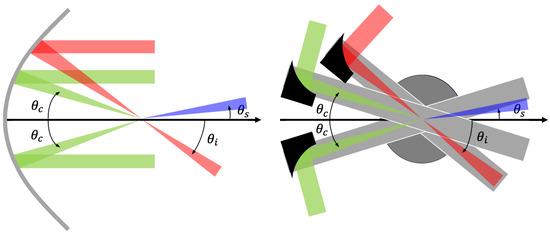
Figure 2.
Two proposals for variable angle mechanisms. The green beams are creation lasers, the red beam is an inducing laser, and the blue beam indicates signal photons. Left: parabolic mirror type where the collision angle is changeable by changing the incident position of lasers. Right: rotating stage type where the collision angle is changeable by assembling a beam focusing system on multiple rotary stages.
Table 1 shows a comparison between two ideas based on the advantages and disadvantages. While the parabolic mirror type has the advantages of fewer optical components and readiness of the angle adjustment, it is necessary to prepare a custom-made large-area mirror to reach heavier mass region with large incident angles and . The search must be performed in a vacuum chamber in order to reduce four-wave mixing (FWM) originating from ambient atoms. Therefore, a large parabolic mirror is not suitable for implementing it in the vacuum chamber. We also note that the focal length must slightly change for individual incident angles.

Table 1.
Comparison of variable-angle mechanisms.
On the other hand, the rotary stage type allows scanning over a wide range of incident angles in a compact size. In addition, it can be constructed using a combination of commercial products, hence having the advantage of flexibility for the design so that we can replace focusing mirrors as we need. As we demonstrated in the previous pilot search [21], we indeed found that it was necessary to prepare a space for a target holder at the focal point to ensure the spatiotemporal synchronization of three pulses, a camera system to record the beam profile, and a shielding wall to suppress background from beam remnants. This requires lots of flexibility including changing the focal length, which has an impact on the sensitivity. However, there is a disadvantage of the rotary stage type in narrow incident angles because focusing optical elements spatially overlap between two incident creation beams.
Therefore, in this study, we adopted the hybrid concept combining good futures of the parabolic mirror type and the rotary stage type depending on incident angles of creation lasers. For large incident angles, the design is based on the rotary stage type with two moving stages for individual creation beams while the inducing beam is fixed at an optical table (LA collider). For narrow incident angles, on the other hand, one of the two creation beams and the inducing beam share a common parabolic focusing mirror and the mirror is fixed at the optical table while the remaining creation beam rotates together with a moving stage (NA collider). In the next section we discuss the relation between LA and NA setups in detail.
The variable-angle mechanism using the rotary stages associates additional complications. The rotary stages consist of individual aluminum plates placed on individual rotating stages. On the individual aluinum plate, a periscope (PS) and a parabolic mirror (PM) to focus a beam are assembled. The incident angles are changeable by rotating the stage. Changing incident angles must accompany changes of incident points of laser beams. However, typically the laser incident point is not readily movable because high-intensity laser systems are not compact. In order to compensate for this immobility, we introduce periscope (PS) components as shown in the picture of Figure 3. PS consists of a pair of mirrors aligned vertically with the angle of incidence (AOI) of 45°. PS can bend a beam in any directions by rotating the direction of the mirror in the upside of the PS. The height of an optical axis is changeable by adjusting the relative distance between the two mirrors in the incident and outgoing sides. The change of incident angles is compensated by the parallel movement of the mirror (M) along the x-axis rail stage in advance of injection to the PS. However, since PS reflects a beam to PM with a possibly large angle, it is necessary to evaluate the effect that the incident linearly polarized state becomes an elliptically polarized one. As we demonstrated in the pilot search, the change of the polarization state can be evaluated based on the measurement of Stokes parameters [21]. In this collision system, incident angles are changeable without moving the collision point by setting the PM’s focal point at the common center of the rotating stages (RSs). The focal spots can be checked using a camera which also rotates around the center. By stacking layers consisting of an aluminum plate and a rotating stage, the collision angle of the three beams can be independently varied. We note, however, that it is not necessary to change the angles of all three colliding beams. As we discuss later, one of the three beams can be fixed and we have only to adjust the AOIs of the other two laser beams relative to the fixed one.
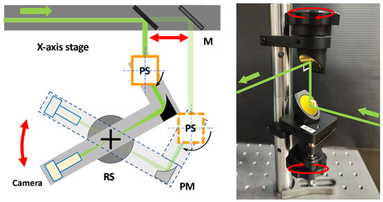
Figure 3.
Variable angle mechanism using a rotary stage. The incident angle is varied by rotating a stage assembling a beam-focusing system with a periscope (PS) and a parabolic mirror (PM). By using a periscope (PS), the angle is changeable only by rotating the periscope (PS) and the mirror (M) on the x-axis rail stage in front of PS. By setting the parabolic mirror’s focal point at the center of the rotary stage (RS), the collision point remains fixed even when the incident angle is varied. The focal spots can be checked using a monitoring camera.
4. Concrete Designs for the Large- and Narrow-Angle Setups
Figure 4 shows side views of the designed collision systems. First, the three beam interaction point (IP) is defined with the center of two thin crossed wires. The wire target must be immovable with respect to the multi-layer stage movements as discussed below. The common layers between the LA and NA collision cases are the bottom signal sampling layer and the top camera layer to monitor beam profiles at IP. The signal layer is necessary to move the detection point of generated signal photons because the signal direction must change depending on collision angles. We introduce two layers for the two creation laser beams in the LA collision case, while only one layer for one of the two creation laser beams is necessary in the NA collision case because the other creation and the inducing beams share a common parabolic mirror which is fixed to the optical table. The breakdown of the individual layers from the bottom are thus as follows: signal light (black), creation light 1 (cyan), creation light 2 (purple), and camera system (magenta) for LA and signal light (black), creation light 2 (purple), and camera system (magenta) for NA.
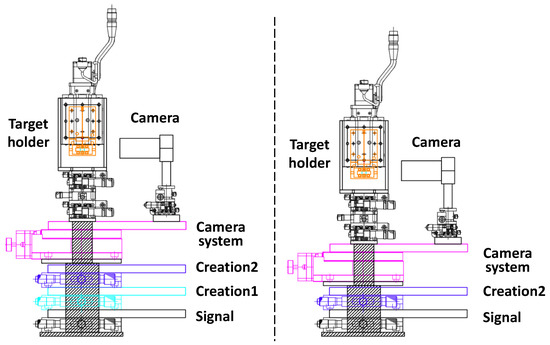
Figure 4.
Side views of designed variable-angle three-beam stimulated resonant photon colliders for large-angle (left) and narrow-angle (right) setups. Detailed explanations are found in the main text.
At IP, a tower-like spacer is placed to introduce an immovable target which must be independent of movements of the four or three rotating stages. The target consists of three components with different positions aligned along a common vertical line: thin crossed wires to calibrate space overlap between the three beams, a nonlinear optical crystal, BBO, to calibrate synchronization of three laser pulses, and an empty hole to perform the search in the vacuum. The target holder is attached to an automated stage that can move vertically to select the three components depending on the purposes. The dynamic range of incident angles is determined by the geometric limitation of the optical elements. At shallow collision angles, parabolic mirrors start interfering with each other, while at wide collision angles, aluminum layers start interfering with each other.
Figure 5a shows the rotary-stage-type geometries in the LA setup covering a large-angle range from 24.8 deg (left) to 47.9 deg (right). The search eventually must be conducted in a vacuum chamber to suppress the atomic background processes. Therefore, we aim at a compact design that can be housed in a vacuum chamber. The incoming laser from the left represents the creation beam 1, creation beam 2, and inducing beam (c1, c2, i), respectively. The beam-like objects after the focal point represent the second harmonic generation (SHG) and the four-wave mixing photons corresponding signal photons (s). In order to guide the generated signal photons to a sensor (photomultiplier, PMT), a calibration laser mimicking signal photon trajectories and the wavelength is necessary. The red inducing beam can be fixed at the bottom optical table in the vacuum chamber, while the incident angles of the other beams can be aligned relative to this beam. The incident angles are changeable by rotating creation stages, which requires re-adjustment of PS and M on the one-axis stage as illustrated in Figure 3, respectively. Figure 5b shows the rotary-stage-type geometries combined with the parabolic-type geometry in the NA setup covering a narrow-angle range from 9.3 deg (left) to 24.8 deg (right). The inducing beam and one of the two creation beams share the common parabolic mirror fixed at the bottom optical table in the vacuum chamber. The narrow angle incidence is realizable by changing the position of incidence of the inducing beam on the surface of the common parabolic mirror by fixing the c1 creation beam.
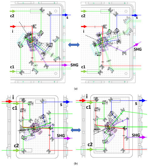
Figure 5.
Collisional geometries viewed from the top. (a) Large-angle setup from deg (left) to deg (right) and (b) narrow-angle setup from deg (left) to deg (right). The details can be found in the main text.
Figure 6 shows a top view of the top common camera layer together with a picture assembling all the components. By preparing an independent layer only for the camera with a motorized rotation stage, beam profiles of all the three lasers at IP can be monitored and recorded. By reading the scale on the motorized rotation stage, the camera position can be adjusted to the incident angles relative to the bisecting line (dashed line) which is set by with respect to the inducing beam direction. We note that the camera position must be calibrated so that the camera surface is placed perpendicularly to the radial direction from the central IP position with an equal distance for any rotated positions. By changing the camera position along the radial direction aligned to IP by the local stage on which the camera is installed, one can check whether a beam profile center stays at the same pixel point in the camera or not. If there is a drift of the profile center, that is, a deviation from the perpendicular direction, one can locally fine-tune the camera positions. With this fine-tuning method, AOIs can be adjusted with sufficient accuracy of 0.1°.
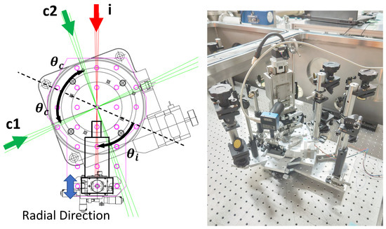
Figure 6.
Left: top view of the camera system on the top layer of the rotary stages to monitor focal spots of all the three lasers c1, c2, and i. Right: picture assembling all the components for the large-angle setup. The details can be found in the main text.
5. Verification of the Rotary Stage System
A three-beam SRPC covering for the LA collision case was actually constructed after testing alignments of PS and PM on individual stages. Since the LA setup contains more rotary layers than the case of the NA setup, the verification of the LA setup guarantees the success of the NA case. The spatial overlapping was then verified using a He:Neon laser. Figure 7, Figure 8 and Figure 9 show the three collision geometries with incident angles of the creation beam at , 35.5, and 47.9 degrees, and the respective focal images of the three beams taken by a single camera are shown. The optical paths of two creation beams, an inducing beam (c1, c2, i), and signal photons (s) are drawn for the reference. The focal images in the middle column show the spot profiles when two crossed wires with a common 10 m diameter were placed in front of the three beams (c1, c2, i) with a smaller beam diameter of 0.8 mm for the two creation beams and 2 mm for the inducing beam to have broader focal images on purpose, while the focal images in the right column show the spot profiles at the same camera position after moving the target holder to the position for the search mode (empty hole) by changing beam diameters to a common 5 mm which will be used for the future search. We note the exact focal lengths of the common creation beams and the inducing beam were 101.6 mm 203.2 mm, respectively.
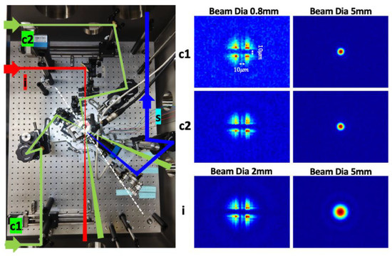
Figure 7.
Picture of large-angle setup (left) and focal images of three individual beams (right) when lasers with a common beam diameter of 5 mm are focused into IP at degree. In the picture, the optical paths of the three beams, consisting of the creation beam (c1), the creation beam (c2), and the inducing beam (i), as well as the signal photon line (s) are drawn. The middle column shows the images of three individual lasers when they hit the crossed point between two thin target wires of a 10 m diameter.
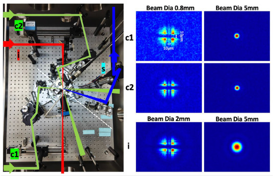
Figure 8.
Picture of large-angle setup (left) and focal images of three individual beams (right) when lasers with a common beam diameter of 5 mm are focused into IP at degree. The other details are the same as in Figure 7.
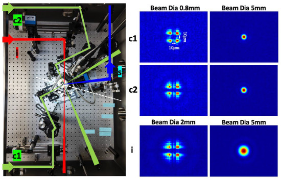
Figure 9.
Picture of large-angle setup (left) and focal images of three individual beams (right) when lasers with a common beam diameter of 5 mm are focused into IP at degree. The other details are the same as in Figure 7.
6. Realistic Sensitivity Projections
We provide sensitivity projections based on the LA and NA collision setups in the following. Figure 10 shows incident angles of the inducing beam as a function of ALP mass which is determined by the incident angles of creation beams and their wavelengths. We plan to use three combinations of laser wavelengths for fundamental, second harmonic and third harmonic cases. Namely, beginning with 800 nm (Ti:Sapphire) for two creation beams and 1064 nm (Nd:YAG) for an inducing beam denoted as nm (red), we extend the search to those with nm (blue) and nm (magenta). Depending on the combinations between the two angle setups and laser wavelengths, accessible mass ranges are different. The figure shows our projections to cover from 0.5 to 6.9 eV with colored arrows corresponding to different wavelengths combinations where accessible mass ranges are specified.
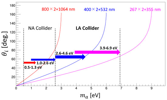
Figure 10.
Incident angles of the inducing beam as a function of ALP masses which are determined by incident angles of creation beams . Three combinations of laser wavelengths for fundamental, second harmonic, and third harmonic cases. Namely, beginning with 800 nm (Ti:Sapphire) for two creation beams and 1064 nm (Nd:YAG) for an inducing beam expressed as nm (red), we extend the search to those with nm (blue) and nm (magenta). Depending on the combinations between the two angle setups and laser wavelengths, accessible mass ranges are different. This figure shows projections to cover from 0.5 to 6.9 eV.
Accordingly, Figure 11 shows the sensitivity projects based on parameters summarized in Table 2. Based on the set of realistic experimental parameters P in Table 2, the observed number of signal photons via an ALP exchange with the mass and the coupling to two photons is expressed as
where is the overall detection efficiency and is the number of shots. A coupling constant can be numerically calculated by solving Equation (5) for an ALP mass and a given observed number of photons . We assumed the as the noise originating photon-like signals . NA, NA, LA and LA are sensitivities corresponding to the individual arrows classified in Figure 10. The details of the numerical calculations and the derivation of the upper limits on the coupling can be found in [20,21], respectively. The red shaded area shows the excluded range based on SRPC in quasi-parallel collision geometry (SAPPHIRES01) [19]. The red filled area indicates the excluded range with the fixed angle pilot search, 00 [21]. The gray area shows the excluded region by the vacuum magnetic birefringence experiment (PVLAS [22]). The purple areas are excluded regions by the Light-Shining-through-a-Wall (LSW) experiments (ALPS [23] and OSQAR [24]). The light-cyan horizontal solid line indicates the upper limit from the search for eV (pseudo)scalar penetrating particles in the SPS neutrino beam (NOMAD) [25]. The horizontal dotted line is the upper limit from the Horizontal Branch observation [26]. The blue areas are exclusion regions from the optical MUSE-faint survey [27,28,29,30,31,32]. The green area indicates the excluded region by the helioscope experiment CAST [31]. The yellow band and the upper solid brown line are the predictions from the benchmark QCD axion models: the KSVZ model [33] with and , respectively, while the bottom dashed brown line is the prediction from the DFSZ model [34] with . The cyan lines are the predictions from the ALP miracle model [12] with the model parameters .
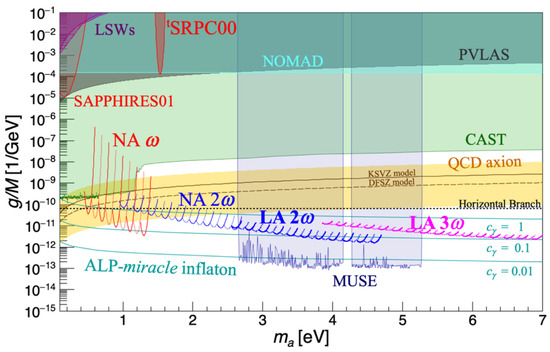

Table 2.
Experimental parameters used to numerically calculate the upper limits on the coupling–mass relations. We note that the focal length of the inducing beam in the case of the narrow-angle setup must slightly vary in principle because of the nature of the parabolic mirror. However, since the incident position with respect to the focusing mirror does not vary a lot, for simplicity, we assume a common focal length to evaluate the sensitivity.
7. Conclusions and Future Plans
We have designed two types of variable-angle stimulated resonant photon colliders with three laser beams () covering narrow and large angles, respectively. The large-angle setup sensitive to a relatively higher mass range was actually constructed, and the mechanism was verified using a He:Neon laser for the calibration. We confirmed that the incident angle can be varied by using a rotating stage and a periscope, and we ensured the spatial overlapping of three beam focal spots at multiple collision angles by developing a monitoring system that allows a single camera to check the focal spot images. As in the previous pilot search at the fixed incident angle [21], time synchronization is expected to be ensured by switching the focal point target to a nonlinear crystal, BBO, and using a delay line with a retro-reflector when a high-intensity laser is used.
Given the realistic designs for both narrow- and large-angle setups, we have provided sensitivity projections in the near future searches for ALPs based on with possible combinations of three laser wavelengths. The sensitivity projects show that the proposed collider can reach coupling domains relevant to the QCD axion models and the Miracle scenario over the mass range of 0.5–6.9 eV within the present reach of laser technologies.
Author Contributions
Conceptualization, K.H.; methodology, T.H.; software, Y.K.; validation, Y.K.; formal analysis, T.H.; data curation, T.H.; writing—original draft preparation, T.H. and K.H.; writing—review and editing, K.H.; visualization, T.H. and K.H.; supervision, K.H.; project administration, K.H.; funding acquisition, K.H. All authors have read and agreed to the published version of the manuscript.
Funding
This research was funded by Grants-in-Aid for Scientific Research Nos. 21H04474 from the Ministry of Education, Culture, Sports, Science, and Technology (MEXT) of Japan.
Data Availability Statement
Not applicable.
Acknowledgments
K. Homma acknowledges the support of the Collaborative Research Program of the Institute for Chemical Research at Kyoto University (Grant Nos. 2023–101) and Grants-in-Aid for Scientific Research Nos. 21H04474 from the Ministry of Education, Culture, Sports, Science and Technology (MEXT) of Japan. Y. Kirita acknowledges support from a Grant-in-Aid for JSPS fellows No. 22J13756 from the Ministry of Education, Culture, Sports, Science and Technology (MEXT) of Japan.
Conflicts of Interest
The authors declare no conflict of interest.
References
- Nambu, Y.; Jona-Lasinio, G. Dynamical model of elementary particles based on an analogy with superconductivity. Phys. Rev. 1961, 122, 345. [Google Scholar] [CrossRef]
- Goldstone, J. Field theories with ≪ Superconductor≫ solutions. Il Nuovo Cim. 1961, 19, 154–164. [Google Scholar] [CrossRef]
- Goldstone, J.; Salam, A.; Weinberg, S. Broken symmetries. Phys. Rev. 1962, 127, 965. [Google Scholar] [CrossRef]
- Weinberg, S. A new light boson? Phys. Rev. Lett. 1978, 40, 223. [Google Scholar] [CrossRef]
- Wilczek, F. Problem of Strong P and T Invariance in the Presence of Instantons. Phys. Rev. Lett. 1978, 40, 271. [Google Scholar] [CrossRef]
- Peccei, R.D.; Quinn, H.R. CP Conservation in the Presence of Pseudoparticles. Phys. Rev. Lett. 1977, 38, 1440. [Google Scholar] [CrossRef]
- Peccei, R.D. The Strong CP problem and axions. Lect. Notes Phys. 2008, 741, 3–17. [Google Scholar] [CrossRef]
- Preskill, J.; Wise, M.B.; Wilczek, F. Cosmology of the invisible axion. Phys. Lett. B 1983, 120, 127. [Google Scholar] [CrossRef]
- Abbott, L.F.; Sikivie, P. A cosmological bound on the invisible axion. Phys. Lett. B 1983, 120, 133–136. [Google Scholar] [CrossRef]
- Dine, M.; Fischler, W. The not-so-harmless axion. Phys. Lett. B 1983, 120, 137–141. [Google Scholar] [CrossRef]
- Daido, R.; Takahashi, F.; Yin, W. The ALP miracle: Unified inflaton and dark matter. J. Cosmol. Astropart. Phys. 2017, 2017, 044. [Google Scholar] [CrossRef]
- Daido, R.; Takahashi, F.; Yin, W. The ALP miracle revisited. J. High Energy Phys. 2018, 2018, 104. [Google Scholar] [CrossRef]
- Fujii, Y.; Homma, K. An approach toward the laboratory search for the scalar field as a candidate of Dark Energy. Prog. Theor. Phys. 2014, 126, 531–553, Erratum in Prog. Theor. Exp. Phys. 2014, 2014, 089203. [Google Scholar] [CrossRef]
- Homma, K.; Kirita, Y. Stimulated radar collider for probing gravitationally weak coupling pseudo Nambu-Goldstone bosons. J. High Energy Phys. 2020, 2020, 95. [Google Scholar] [CrossRef]
- Homma, K.; Hasebe, T.; Kume, K. The first search for sub-eV scalar fields via four-wave mixing at a quasi-parallel laser collider. Prog. Theor. Exp. Phys. 2014, 2014, 083C01. [Google Scholar] [CrossRef][Green Version]
- Hasebe, T.; Homma, K.; Nakamiya, Y.; Matsuura, K.; Otani, K.; Hashida, M.; Inoue, S.; Sakabe, S. Search for sub-eV scalar and pseudoscalar resonances via four-wave mixing with a laser collider. Prog. Theor. Exp. Phys. 2015, 2015, 073C01. [Google Scholar] [CrossRef]
- Nobuhiro, A.; Hirahara, Y.; Homma, K.; Kirita, Y.; Ozaki, T.; Nakamiya, Y.; Hashida, M.; Inoue, S.; Sakabe, S. Extended search for sub-eV axion-like resonances via four-wave mixing with a quasi-parallel laser collider in a high-quality vacuum system. Prog. Theor. Exp. Phys. 2020, 2020, 073C01. [Google Scholar] [CrossRef]
- The SAPPHIRES Collaboration; Homma, K.; Kirita, Y.; Hashida, M.; Hirahara, Y.; Inoue, S.; Ishibashi, F.; Nakamiya, Y.; Neagu, L.; Nobuhiro, A.; et al. Search for sub-eV axion-like resonance states via stimulated quasi-parallel laser collisions with the parameterization including fully asymmetric collisional geometry. J. High Energy Phys. 2021, 2021, 108. [Google Scholar] [CrossRef]
- The SAPPHIRES Collaboration; Kirita, Y.; Hasada, T.; Hashida, M.; Hirahara, Y.; Homma, K.; Inoue, S.; Ishibashi, F.; Nakamiya, Y.; Neagu, L.; et al. Search for sub-eV axion-like particles in a stimulated resonant photon-photon collider with two laser beams based on a novel method to discriminate pressure-independent components. J. High Energy Phys. 2022, 2022, 176. [Google Scholar] [CrossRef]
- Homma, K.; Ishibashi, F.; Kirita, Y.; Hasada, T. Sensitivity to axion-like particles with a three-beam stimulated resonant photon collider around the eV mass range. Universe 2023, 9, 20. [Google Scholar] [CrossRef]
- Ishibashi, F.; Hasada, T.; Homma, K.; Kirita, Y.; Kanai, T.; Masuno, S.; Tokita, S.; Hashida, M. Pilot search for axion-like particles by a three-beam stimulated resonant photon collider with short pulse lasers. Universe 2023, 9, 123. [Google Scholar] [CrossRef]
- Ejlli, A.; Della Valle, F.; Gastaldi, U.; Messineo, G.; Pengo, R.; Ruoso, G.; Zavattini, G. The PVLAS experiment: A 25 year effort to measure vacuum magnetic birefringence. Phys. Rep. 2020, 871, 1–74. [Google Scholar] [CrossRef]
- Ehret, K.; Frede, M.; Ghazaryan, S.; Hildebrandt, M.; Knabbe, E.A.; Kracht, D.; Lindner, A.; List, J.; Meier, T.; Meyer, N.; et al. New ALPS results on hidden-sector lightweights. Phys. Lett. B 2010, 689, 149–155. [Google Scholar] [CrossRef]
- Ballou, R.; Deferne, G.; Finger, M., Jr.; Finger, M.; Flekova, L.; Hosek, J.; Kunc, S.; Macuchova, K.; Meissner, K.; Pugnat, P.; et al. New exclusion limits on scalar and pseudoscalar axionlike particles from light shining through a wall. Phys. Rev. D 2015, 92, 092002. [Google Scholar] [CrossRef]
- Astier, P.; Autiero, D.; Baldisseri, A.; Baldo-Ceolin, M.; Ballocchi, G.; Banner, M.; Bassompierre, G.; Benslama, K.; Besson, N.; Bird, I.; et al. Search for eV (pseudo) scalar penetrating particles in the SPS neutrino beam. Phys. Lett. B 2000, 479, 371–380. [Google Scholar] [CrossRef]
- Ayala, A.; Domínguez, I.; Giannotti, M.; Mirizzi, A.; Straniero, O. Revisiting the bound on axion-photon coupling from Globular Clusters. Phys. Rev. Lett. 2014, 113, 191302. [Google Scholar] [CrossRef]
- Regis, M.; Taoso, M.; Vaz, D.; Brinchmann, J.; Zoutendijk, S.L.; Bouché, N.F.; Steinmetz, M. Searching for light in the darkness: Bounds on ALP dark matter with the optical MUSE-faint survey. Phys. Lett. 2021, 814, 136075. [Google Scholar] [CrossRef]
- CAST Collaboration. Probing eV-scale axions with CAST. J. Cosmol. Astropart. Phys. 2009, 02, 008. [Google Scholar]
- CAST Collaboration. Search for Sub-eV Mass Solar Axions by the CERN Axion Solar Telescope with 3He Buffer Gas. Phys. Rev. Lett. 2011, 107, 261302. [Google Scholar] [CrossRef]
- CAST Collaboration. Search for Solar Axions by the CERN Axion Solar Telescope with 3 He Buffer Gas: Closing the Hot Dark Matter Gap. Phys. Rev. Lett. 2014, 112, 091302. [Google Scholar] [CrossRef]
- CAST Collaboration. New CAST limit on the axion-photon interaction. Nat. Phys. 2017, 13, 584. [Google Scholar] [CrossRef]
- Kim, J.E. Weak-Interaction Singlet and Strong CP Invariance. Phys. Rev. Lett. 1979, 43, 103. [Google Scholar] [CrossRef]
- Shifman, M.A.; Vainshtein, A.I.; Zakharov, V.I. Can confinement ensure natural CP invariance of strong interactions? Nucl. Phys. B 1980, 166, 493–506. [Google Scholar] [CrossRef]
- Zhitnitskii, A.P. Possible suppression of axion-hadron interactions. Sov. J. Nucl. Phys. 1980, 31, 260. [Google Scholar]
Disclaimer/Publisher’s Note: The statements, opinions and data contained in all publications are solely those of the individual author(s) and contributor(s) and not of MDPI and/or the editor(s). MDPI and/or the editor(s) disclaim responsibility for any injury to people or property resulting from any ideas, methods, instructions or products referred to in the content. |
© 2023 by the authors. Licensee MDPI, Basel, Switzerland. This article is an open access article distributed under the terms and conditions of the Creative Commons Attribution (CC BY) license (https://creativecommons.org/licenses/by/4.0/).