1. Introduction
To date, our species has successfully sent robotic space probes to nearly all of the planetary objects of our solar system. This has, therefore, begun the age of interplanetary exploration and will pave the way to full planetary colonization of some of these worlds. Yet, we have also sent space probes outside of the solar system. This includes the Voyager 1 and 2 missions, which were launched in the 1970s and are now travelling at around 17 km/s and are currently at ∼130 AU and ∼155 AU, respectively, where 1 AU = m.
These spacecraft rely on a chemical propulsion method which is based upon hydrazine thrusters and is used for trajectory manoeuvring. However, most of their velocity comes from the original launch boost onto their heliospheric trajectory from a rocket. The sun kept pulling the Voyagers back down in velocity, but this was mitigated by several gravity assists via Jupiter and Saturn for Voyager 1, and via Jupiter, Saturn, Uranus and Neptune for Voyager 2. Without the use of gravity assists, the Voyagers would not have achieved solar system escape velocity.
To go beyond the solar system even further still, perhaps to one light year (
) at around ∼65,000 AU will require a propulsion technology that has a performance far exceeding that of chemical reactions, but will surely bring enormous benefits to our scientific studies of the universe [
1]. Fortunately this issue has been well studied by others [
2,
3,
4,
5,
6]. Nuclear fission offers good potential since the energy associated with the fragmentation of an atomic nucleus is a million times more energetic than a simple chemical reaction associated with molecular collisions. However, although nuclear fission will enable missions far into deep space, it is still insufficient to enable missions over an interstellar distance that exceeds around ∼4
.
There are other options for sending probes to interstellar distances, and this includes using laser beaming methods. Such a proposal was investigated in the 1970s under the name Starwisp; it would facilitate 1 ton payloads travelling at 0.11 c [
7]. However, such missions would require vast assemblies of Fresnel lenses in orbit to re-collimate the beam and maintain the pressure on the sail [
8]. This project has since been re-visited under the name Starshot [
9], and this involves the sending of gram-scale probes at 0.2 c over interstellar distances using a ∼100–200 GW ground based beaming array. Although this has huge potential in terms of scientific discoveries, the probes are very small, and so the types of payloads that can be facilitated are limited.
Another option would be the use of antimatter–matter annihilation reactions, such as through the collision of a proton and anti-proton [
10,
11]. Such reactions can offer as much as ∼90 billion MJ/kg specific energy. Some have even considered the possibility of combining antimatter reactions with fusion reactions [
12,
13]. However, it is not known how antimatter can be stored and controlled in an appropriate way, let alone how it can be properly mined. It is therefore considered a breakthrough propulsion technology that is currently outside the scope of our near-term capability, although it may be possible in the future.
If we are to send large mass payloads over interstellar distances, we therefore need a technology which exceeds fission reactions, and has a mass carrying capability that exceeds beam driven propulsion. Yet, it must also be nearer term in technology maturation compared to antimatter so that it has practical realisability. The answer is offered from fusion reactions such as those that take place inside the core of a star. In such a reaction, two protons overcome their mutual repulsion through the Coulomb barrier and once combined, release an excess energy that is significant. Indeed, a fusion reaction via hydrogen and helium isotopes will give rise to a specific energy of around ∼350 million MJ/kg, or around ∼ J/g. It would also seem to be serendipitous that we use the same power source that fuels the stars to travel between them.
There are many methods envisaged by which an artificial star can be constructed as a power source; laboratory experiments have been attempting this for many decades. Among the two dozen or so approaches that have been imagined, and this includes the application of space propulsion (i.e., recent research on direct fusion drive [
14,
15]), there are two dominant pathways in particular.
When one thinks of fusion research in the commercial industry, this is usually associated with magnetic confinement fusion (
MCF), which utilises a low number density (
n∼
cm
) of fusion particles at high temperature (
T∼10 keV) for a relatively long (
∼s) confinement time. The goal of any fusion method is to achieve the ignition conditions, where
This is also known as the fusion triple product or the Lawson criteria [
16]. However, a problem with this type of magnetic fusion technology in its application to space travel is the high mass associated with its various components, such as the magnets. This method will not be discussed any further in this work, but we point the reader to other research for the potential [
17].
This work has instead focussed on another method of igniting fusion fuels, known as inertial confinement fusion (ICF). This uses a high number density (∼ cm) of particles, in which a small sub-gram capsule of low mass isotopes (typically hydrogen, deuterium, tritium and helium) is compressed to extremely high density (∼1000 s) and temperature (T∼10 s keV), whilst being inertially confined in that state for a sufficiently short period (∼n s) so that fusion ignition can be initiated within a hot-spot region, which then propagates outwards as a thermonuclear burn wave. This specific method of ICF ignition physics is the focus for the remainder of this paper. In particular, an overview is presented of the key physics and engineering issues involved, and we also illustrate the potential by the examination of several case studies from the literature.
The confinement of a fusion capsule is complicated by the interaction of the beam, where for an optical laser irradiation scenario, mass is initially lost to the surface via ablation and sets up a coronal plasma layer, limiting penetration to a critical density surface, and instead it is absorbed into the electrons, mainly by collisional inverse Bremsstrahlung, collisionless resonance absorption and parametric instabilities. The electrons transport the energy inwards to transfer their energy into the thermal energy of the compression. Convergent shocks with an implosion velocity of ∼ then compress the fusion fuel up to 100 times that of the lead, producing a high-temperature, ∼, hot spot at the centre of the capsule, so the fusion reactions can begin depositing alpha particles into the surrounding high density, but cooler fuel, defining the point of ignition. Provided that this burn up occurs faster than the time for the capsule to expand under its own pressure, then 10 s MJs of energy could be liberated, in principle.
The objective is to achieve energy gain, i.e., more energy would be released from the fusion reaction than the driver energy required to achieve the compression and burn. To achieve this process in a spacecraft is no small challenge. The spacecraft must have the apparatus of a driver beam (i.e., optical laser) and some way of accelerating the capsules into the target chambers. Energy driver beams would then confine each capsule for a fraction of a second until ignition conditions are achieved. This entire operation is a technical challenge in itself, even for a reactor stationed on Earth.
This paper will firstly discuss the interaction of a laser beam with the surface of an ICF capsule by discussing the relevant plasma physics equations and demonstrating the simulation of a particle-in-cell calculation. The key physics equations relevant to the application of this method into an advanced spacecraft propulsion engine are then discussed. Some of the historical concepts in the literature that have proposed the use of an ICF engine within an integrated spacecraft design are then reviewed, and by this it is shown how the thinking has evolved to the current concepts. Finally, the paper ends with a brief discussion on the burn fraction for the different models. Although spacecraft propulsion via ICF is still far from technological maturation, the concepts that are being developed at least imply that it may be a plausible part of our future. In terms of considering the technological and strategic roadmaps for interplanetary and interstellar exploration, the advanced propulsion using ICF may be critical to the opportunities ahead.
2. Laser Interaction with Fusion Capsule
The ignition of a capsule (also known as a pellet) to a state where thermonuclear fusion can occur is non-trivial and involves many stages. This is further complicated in the context of a space propulsion engine, where many capsules must be imploded at a set repetition rate (also called pulse frequency). It is necessary to describe the various steps involved in this process between cycles of one capsule detonation to another. These steps are now outlined in turn, and within the context of a reaction chamber, as is typically used in advanced space propulsion, this is illustrated in
Figure 1. To keep things simple, it is assumed that there is an array of optical laser drivers on a direct drive capsule target. However, it is important to understand that the ignition engine could operate in different ways, such as by using indirect drive or fast ignition methods as mentioned.
The physics processes that take place are highly complex, from the interaction of the laser beam with the capsule and the resulting laser plasma interactions, to the hydrodynamic compression of the fuel with high symmetry and minimum instabilities. A symmetrical compression of a capsule is measured by the ratio of the initial outer ablator radius
to the final hot spot radius
and is given by
In general, values for successful compression of a capsule are 30–40. To achieve these, any accelerations or perturbations of the imploding shell should not exceed around ∼1% deviation from perfect symmetry. This is one of the justifications for the indirect drive ignition since the radiation cavity facilitates a smoother implosion symmetry and fewer instabilities. The nature of these may be due to a Rayleigh–Taylor (RT) instability, where two materials of different density results in the heavier material entering the lighter one at the material interface. Another may be due to a Kelvin–Hemholtz (KH) instability, where the materials at an interface are moving at a different shear velocity. A further possibility may be due to a Richtmyer–Meshkov (RM) instability where the two materials of a different density will be impulsively accelerated due to a shock wave. For an ICF capsule, the material interface will be at the ablator shell to the fuel boundary, or it may be at the boundary of two different fuel materials within the capsule where they have a different density. Any of these has the potential to give rise to an altered burn fraction on the capsule performance due to shock surface interactions.
As mentioned, the successful ignition of the fusion fuel depends on achieving the fusion triple product, the generation of a sustained thermonuclear burn wave and then disassembly of the capsule as it explodes outwards in a high temperature plasma state [
18,
19,
20]. Whilst the technology is still being investigated in Earth-based laboratories for the application of national grid commercial power generation, here, the extended application of this technology to the advanced propulsion of a spacecraft on an interstellar trajectory is considered. In addition to correctly understand the ignition physics of the capsule and its predicted output performance, one must also understand the interaction of the output effects onto the spacecraft vehicle structure—mainly through X-ray Bremsstrahlung radiation and high energy neutrons, which will radiate the materials, causing significant structural heating and fatigue.
The physics requirements for the ignition of a typical ICF capsule are made difficult by the need to firstly achieve sufficient compression of the fuel and the central hotspot. Secondly, there is the need to achieve hot-spot ignition and alpha particle deposition for sustained burn. In terms of the capsule design itself and the method of how it is ignited, there are many schemes that have been proposed for how this can be achieved, and it is worthwhile to briefly compare them.
Table 1 shows a comparison of four different methods that will be briefly discussed, known as direct drive, indirect drive, shock ignition and fast ignition.
Direct drive is likely the most appropriate route for space propulsion if the instabilities can be overcome and a high symmetry of implosion is maintained. This can be achieved by the use of long pulse lasers. Indirect drive is an attempt to smooth out the instabilities by providing for a uniform radiation bath around the capsule. This is achieved by placing the capsule within a cavity (known as a Hohlraum), and the lasers are fired onto the surface of that cavity from which X-rays are emitted [
21]. This is the route currently being pursued by the US National Ignition Facility (NIF) [
22,
23] and the French Laser Megajoule (LMJ) [
24].
Fast ignition [
25,
26] is an attempt to separate out the compression phase due to the hydrodynamic implosion, from the thermonuclear ignition phase. It has been argued that the gain from a fast ignition model may be much higher than for a conventional direct drive or indirect drive hot spot approach. It proposes to use a long pulse laser for the compression, and just prior to the hot spot ignition condition being met, a short pulse ∼1–100 ps laser is then fired in to complete the process. The short pulse laser may either enhance the earlier pulse through further heating, or alternatively generate a hot electron beam, which can penetrate the fuel.
A problem with this approach, however, is that the electrons have to penetrate through all the high-density plasma without being stopped. A way to solve this is to use a long pulse laser to compress the fuel but to have a gold cone in part of the capsule that tapers off at an angle from the axis. A short pulse laser beam is fired down this channel, impinging on the gold cone tip and causing the generation of electrons at the tip, which go straight into the central hot spot to ignite the fuel. The problem with this method is that the generated electrons do not leave the tip as a collimated beam but instead diverge widely so that only a fraction of the electrons produced will actually reach the central hot spot. Another problem with this approach is that the act of passing the laser beam down the channel causes plasma infilling, which is an obstacle to the continued laser transport. Some of the laser energy will be scattered, reducing the laser-capsule coupling efficiency.
Shock assisted ignition [
27,
28,
29] is a different approach altogether and moves away from the idea of hot spot ignition but also decouples the compression phase from the ignition phase. Instead, the capsule is designed with an unusually thick ablator shell, which makes for a slow implosion velocity and on a low adiabat. This helps to minimise the hydrodynamic instabilities. The capsule will be compressed, and the shock waves will centrally reflect, but on their way out, they will collide with a second incoming shock, and it is at this point that the ignition conditions will be achieved. Since the capsule is imploded on a low adiabat, in principle it can also be imploded with a lower laser energy. Finally, as discussed a little later, it is possible that the shock ignition may give rise to a much higher gain, although this is speculative.
It is important to point out, that many of these ideas are theoretical and depend upon complex physics simulations, although there is some experimental validation of the physics models through facilities such as NIF. Many of the simulations tend to be one dimensional, such as using particle in cell codes or Vlasov solver codes, and when moving to higher dimensions, such as a 2D or 3D code, the benefits of one scheme over another may fall away. This is particularly the case for the modelling of hydrodynamics. That said, as long as there are many ways to approach the problem, the changes of achieving the goal of thermonuclear ignition within a laboratory environment are high. Once capsule designs like this are demonstrated and at high gain, their application in a space propulsion context can also be considered. In this regard, the main issue for spacecraft design is the emission of high energy neutrons and X-rays from the capsule which can radiate the material structure, and this is discussed a little later.
For simplicity, in the remainder of this paper, the focus will be on direct drive ICF and with a hot spot ignition scenario. The capsule will consist of a low atomic mass material, such as hydrogen or helium or combinations thereof, as a ratio mixture, surrounded by a higher density substrate material known as an ablator shell. The spherical material has a radius of order ∼mm and a mass of order ∼mg. A typical capsule design such as that used in the National Ignition Facility is illustrated in
Figure 2. As will be seen, a major difference between a commercial ground based power reactor and a space propulsion engine is that for the latter, the size and mass of the capsule will likely be much greater. This is to facilitate a large energy release per capsule detonation for thrust generation, which would become unmanageable in a ground-based facility since these are essentially miniature thermonuclear detonations.
For a realistic space propulsion engine, it will be necessary to assume something like each laser firing a total of ∼0.5 MJ of energy, so that with 20 individual optical lines, there will be a total of ∼10 MJ fired at the target. However, for current experimental reactors, the situation is something like a total energy of 1.8 MJ delivered onto a DT gas target at 0.3 mg/cc density up to a radius of 0.9 mm, surrounded by a layer of DT solid up to a radius of 1 mm, then finally an outer ablator layer of CH plastic up to a radius of around 1.1 mm.
For a set-up with many individual beam lines, these are fired onto the target simultaneously and the distance between the beam source and the target is sufficiently small such that the divergence of the beam can be neglected, so that all of the beam spot collectively fully cover the surface area of the capsule with no gaps. Once the laser arrives at the capsule surface, it will ionize the atoms within the layers of the outer ablator shell, leading to a plasma cloud and, in particular, free electrons.
Plasmas will have a natural period of oscillation to respond to any induced fields, defined as the electron plasma frequency
, where the ions can be considered a fixed background or with infinite mass. It can also been seen as the minimum frequency for the propagation of a light wave in a plasma
where the electron mass
kg, the permittivity of free space
Fm
, an electron volt 1 eV = 1.609
C, and the Boltzmann constant
JK
.
Table 2 shows some typical values for the electron plasma frequency for different plasmas, where it can be observed that, compared to other physics systems, the corona of an ICF capsule is characterised by a high number density of particles at high temperature and so a high electron plasma frequency.
At some point, however, the frequency of the laser will become equal to the frequency of the oscillating electrons within the plasma cloud, and this will lead to reflection and scatter of the laser beam. This creates a problem for the propagation of an electromagnetic wave since the implosion of an capsule will depend on the pressure profile generated.
In physics, wave phenomena are described by dispersion relations. These are functions which describe a particle’s position at any time
. The wave velocity can be described as a function of the wavelength
and frequency
f, where the sinusoidal wave oscillations can be defined by a wave number
and angular frequency of the oscillation
, leading to the dispersion relation for a plane light wave in a vacuum.
In plasmas, collective disturbances are transmitted in the form of fluctuations of waves in the electron or ion density. Laser light can interact not just with plasma particles, but also with the plasma waves, which can propagate. These can be electrostatic waves (longitudinal waves with no magnetic component) and are associated with high-frequency, long wavelength oscillations. Alternatively they can be electromagnetic waves (with a transverse component).
The dispersion relation for electromagnetic waves can be found by solving the wave equation in a vacuum. Faraday’s law of induction and Amperes current law are defined by the magnetic flux density
and electric field
as follows:
where the phase velocity is equal to the wave speed or the speed of light in free space
m/s,
is the vacuum permeability or magnetic constant (
NA
) and
is the permittivity of free space (
Fm
). In SI units, the magnetic field
and electric field
will have the units of Wb/m
and V/m, respectively. Taking the curl of the electric field and substituting, it is then found
Then using the vector identity
, and
in a vacuum, and is known as the vacuum Poisson equation. This gives the wave equation for an electromagnetic wave propagating at the speed of light.
This has a plane wave solution of the form
That is to say that Equation (
11) satisfies Equation (
10). In this equation,
is the complex amplitude measured in V/m which represents the longest period in the wave under study, and it is the coefficient of the plane wave solution.
The interaction of an electromagnetic wave with a plasma should then satisfy the following dispersion relation, which is expressed as a function of the wave number
as follows:
An electromagnetic wave will only be able to propagate through a plasma provided it has a frequency greater than the electron plasma frequency, i.e., . If the laser frequency is less than the electron plasma frequency, then it will not propagate. A situation where will not occur because this will lead to an imaginary value. Within the context of a laser beam interacting with the surface of an ICF capsule, this translates from a situation of energy propagation to one of energy absorption and reflection. In any simulations, it will be necessary to model the initiation of the problem by defining the amplitude, which corresponds to the laser.
To illustrate the propagation of a laser through a plasma, the results of a 1-dimensional particle-in-cell (PIC) code simulation performed by this author are shown using a source code [
30,
31]. This represents charged particles by pseudo particles and solves Maxwell’s equations for the electric and magnetic field on a finite difference domain. The particles in the simulation are pushed around by solving the relativistic equation of motion for the momentum
under the Lorentz force for a particle of charge
q and velocity
The calculations were such that the time step control was enabled through the CFL condition and the electron plasma frequency such that the ratio of physical disturbance to numerical information . Efforts were also made to ensure that the numerical resolution was consistent with the Nyquist sampling theorem such that the shortest frequency that was sampled was twice the sampling interval, such that . A large enough number of particles was also important for the minimisation of noise, and sensitivity studies were conducted to verify this.
A left-hand boundary condition was imposed as a laser intensity within the computational domain. Although the material medium was modelled as planar, it was assumed that this was representative of a section of a spherical shell of material that might surround a fusion fuel as is typical in ICF ignition physics. The relevant equations are obtained by combining the Maxwell equation for the curl of the electric field with that for a plane wave solution
Then integrating one is left with an equation for the magnetic field component as well as the electric field at time
as follows
In this specific simulation, attempts were made to simplify the physics as much as possible. The total number of grid points in the problem was , domain size m, and 32,000 particles of species electrons and species ions each for a total of 64,000 particles. The total run time was s. The right boundary condition describes the plasma outflow as a distribution function. The laser was input as a left boundary condition, and the pulse time profile was a representative Gaussian line shape.
A long pulse laser simulation was conducted but with no density ramp (to represent a uniform plasma). For the calculations, the input was in the form of amplitude
Vm
. This was then related to the laser intensity
Wcm
via
where
is the energy density (Jcm
). Alternatively the Amplitude can be described in appropriate units [
20] as follows
A uniform temperature of 0.1 keV (∼12,000,000 K) was assumed. In the single simulation, a laser beam interacts with a hydrogen plasma with a density
The critical density was computed from
The wavelength was
m, and the frequency was
The complexity of these sorts of simulations is non-trivial to analyse. The method of approach is to construct a Fourier transform program (written in IDL) to identify the peak frequency from the output. This involves starting with the initial electric field output and then taking the FFT of , which will produce based on the frequency peak. This then leads to a successful match of the numerical dispersion wave results with theoretical expectations, provided that the numerical code properly models the physics.
An analysis of the results showed that the peak harmonic frequency of the FFT matched the theoretical prediction to high accuracy, showing that the physics was being appropriately modelled. The electron density was
m
and would correspond to an electron plasma frequency of
s
. Since the frequency of the laser is greater than the electron plasma frequency,
, the laser will continue to propagate into the plasma of the ICF capsule surface. The simulation is shown in
Figure 3 for the electric field
as function of x, where the laser can be seen to propagate through the plasma from left to right.
This simulation illustrates how one can model the interaction of a laser beam with an ICF capsule surface. As can be seen, electromagnetism plays a critical role in determining how the material will respond. Although, if the capsule involves multiple material layers and there are multiple beam lines, the modelling can become complex and computationally expensive. Yet, the simulation shows that in modelling the interaction of a laser beam with the surface of an ICF capsule, we are essentially dealing with the propagation of an electromagnetic field through a material medium. A description of this is based on fundamental plasma physics.
Meanwhile, the heat from this process will cause mass ablation of the capsule and the inwards movement of the sphere towards a state of spherical convergence by the mechanism of momentum transport. This leads to the high density compression of the fuel to the order of ∼1000–2000 times the initial cold density, as well as an increase in the temperature to the order of ∼10 keV or greater. Provided that this state is maintained for a continued period (of order ∼ns–s), the fuel will be confined by the material above it, and this will lead to the thermonuclear ignition of the fuel via the hydrogen nuclei overcoming their own Coulomb force.
The creation of a plasma cloud (corona) around the ICF capsule due to the interaction of the hot laser source with the capsule surface sets the conditions for a reduction in the efficiency of the implosion of the capsule. This is because any further laser light must propagate through an ionised layer of ions and electrons and the physics processes at work in that laser–plasma interaction are not all for the benefit of the shell collapse. Instead the laser energy is absorbed into the plasma through various mechanisms [
32] as follows:
Parametric Instability (PI): This is where the incident wave from the laser driver excites counter propagating Langmuir and ion acoustic waves, leading to the conversion of electromagnetic energy into electrostatic modes of the plasma, which will also enhance absorption.
Stimulated Brillouin Scattering (SBS): This is where the incident wave excites and ion acoustic wave within the plasma, but also an electromagnetic wave propagating in the direction opposing the incident wave, thus exiting the plasma and leading to energy loss.
Stimulated Raman Scattering (SRS): This is where the incident wave from the laser again leads to an electromagnetic wave propagating in the opposing direction, but instead of an ion acoustic wave, it produces a forward moving Langmuir wave, which can trap and accelerate electrons to suprathermal speeds heating the fuel ahead of the full compression (electron preheat), thus reducing the implosion efficiency.
Two-Plasmon Decay Instability (TPDI): This is where the incident wave excites two Langmuir waves, which are moving in opposing directions.
Two-Ion Wave Decay Instability (TIWDI): This is where the incident wave excites two ion acoustic waves which are moving in opposing directions.
Langmuir Decay Instability (LDI): This is where a Langmuir wave within the plasma decays into another Langmuir wave and an ion acoustic wave, with the Langmuir wave decaying further into another Langmuir wave and an ion acoustic wave in a process of cascade.
Once a target has been compressed up to a smaller volume, it will have a high number density and temperature, particularly within a central hot spot region. The hydrodynamic compression will lead to the generation of mechanical work through a PdV process adding energy to the hot spot. In addition, once the central hot spot region has ignited, it will begin to generate alpha particles and then deposit them into the surrounding fuel. This will also heat up the material and add energy. Whilst these energy addition processes are occurring, several energy loss mechanisms will be in effect. This includes the loss of energy due to electron thermal conduction away from the central hot spot, as well as radiation loss through the process of Bremsstrahlung emission. The race for the capsule is to inertially confine the central hot spot sufficiently long enough for the energy deposition (and subsequent thermonuclear burn wave) to propagate and fully ignite all of the fuel before the energy loss mechanisms and capsule disassembly can detract energy from it.
In a capsule, typically, it may be assumed that the hot spot has a radius r (cm) and is imploded with a velocity v (cms), is the hot-spot density (g/cm), and T is the hot-spot temperature (keV). Electrons and ions are assumed to be in equilibrium. The total number of particles in the hot spot is defined by (cm). The Maxwell average cross section is defined by which for a DT fuel is around ∼ (cm3s−1) at 1 keV.
Thus, designers will approach the problem from the principle of total energy conservation in that the sum of the energy gains minus the sum of the energy losses should be greater than zero in order to obtain the ignition and eventual gain. The energy gains are represented by the PdV mechanical work per unit volume
and the alpha particle deposition thermonuclear heating rate per unit volume
. The energy losses are represented by the radiation losses (due to Bremsstrahlung emission) per unit volume
and the electron conduction losses (approximated with a Spitzer conductivity) per unit volume
.
Another energy gain term should technically be added to account for the neutron energy deposition, but Ref. [
20] makes the point that this is small and so can be neglected as an approximation.
3. Advanced Spacecraft Propulsion
The performance of an ICF-driven spacecraft engine will be strongly dependent on the type of fusion fuel adopted for the mixture since this is one of the factors that will determine the exhaust velocity. For example, for a deuterium–tritium fusion fuel at an assumed 50:50 mixture, the primary thermonuclear reaction will be
This will produce an expected energy release of around
J/g as shown in
Table 3. This will then determine the performance by a consideration of the atomic mass of the products and the reactants
Then multiply this through the square of the speed of light
to obtain an equation for the exhaust velocity as a function of the fractional energy release
as follows
This shows the theoretical limit of what is possible for fusion-based propulsion. Although a theoretical calculation might suggest very high exhaust velocities approaching ∼27,000 km/s, the reality is that when taking into account the various loss mechanisms due to the driver efficiency and the laser-capsule coupling efficiency, the maximum exhaust velocity will be of order ∼10,000 km/s. This will then imply that cruise speeds of around ∼30,000 km/s or ∼0.1 c are possible, although this can be extended further with the use of serial or parallel engine staging and efficient energy conversion systems up to perhaps as high as ∼0.15 c. Parallel staging was examined by Powell [
33], who found that it gave a rather small advantage in flight time over a series stage system, where the advantage increased as the payload mass fraction was reduced. He also found that parallel staging offered no significant advantage over series staging if the exhaust velocity was much less than the optimal value, which illustrates the importance of design optimisation for a particular mission.
The ultimate goal is to compress this capsule up to a state of high temperature
T and high areal density
. The efficiency of the implosion is measured by a parameter termed the burn fraction
. Once a state of ignition is achieved within a fusion capsule, the amount of energy released depends on the mass of the fuel
, the specific energy of the fuel being reacted
and the burn fraction. These are described together as
The burn fraction will depend on many factors but is a measure of the efficiency of the implosion engine converting the hydrodynamic work to useful energy output. It will be a function of how well the laser driver couples to the capsule, the interaction of the materials within the capsule and the geometrical design of the capsule itself. It is a critical parameter to determining the overall performance of the capsule in any engine design, since the energy output will also affect the spacecraft trajectory and mission profile. This will be discussed in more detail later.
In calculating the performance of a spacecraft being driven by a reaction engine, it is useful to make some simple assumptions. This includes straight line trajectories rather than considering conic sections. This also includes neglecting gravity fields from other astronomical objects. A spacecraft propelled by fusion will be travelling in excess of 10,000 s km/s, and this velocity exceeds even the stellar velocity motions, so these assumptions are reasonable as an approximation.
The fusion engine onboard a spacecraft will likely require a separate nuclear fission power reactor first to initialise it. However, once it is underway, some of the energy release from each detonation can be bootstrapped to help power the next cycle, such as in a magnetic field induction loop. As shown in
Figure 4, the fusion reactions may be initiated in a closed or open reaction chamber, depending on how the charged particles are controlled through the use of magnetic fields.
A significant consideration in ICF ignition is the several pathway energy losses along the way and in propulsion theory, this tends to be expressed as a power cycle as shown in
Figure 5. This begins with any losses in the beamer system in turning it on and powering it up to the sufficient charge and the loss due to any system integrations such that if a system is considered that delivered
but it experienced losses
, then the energy delivered to the target
will be
Then there are the losses associated with the coupling of the laser to the capsule surface, which facilitates its implosion. As described above, some of that energy will be reflected due to the laser–plasma interactions. The losses associated with this laser coupling are
so that the target energy is
Then the losses associated with the direct compression and heating of the fuel are represented by the burn fraction. If the total of these losses is
, then the input that goes into the thermal energy of the implosion
is given by
Once the capsule is successfully ignited, it will release a large amount of thermonuclear fusion energy. This results in a multiple factor called the gain
Q. If
Q < 1, then the system is generating more energy than it is producing in fusion energy. If
Q > 1, then although relative to the thermal energy of the compression it will be producing a positive gain, relative to the original input energy, it may not or it may just break even. It is therefore desirable to have a state where it is a lot greater than unity.
For a commercial civilian power reactor, a gain to the order of ∼10 may be deemed appropriate. However, for the application of space propulsion, a gain to the order of ∼100 would be a more desirable requirement. Instead of energy, these relationships can also be written as power expressions since power is just energy output over some time interval. These are typically expressed as overall power flow diagrams in a space propulsion context. This might include showing the original efficiency of the input laser, laser coupling losses, neutrons, X-rays and plasma debris.
The power release
available for thrust generation from the fusion reactions is some fraction of the plasma debris, and together with the nozzle jet efficiency
, it defines the jet power
of the engine. The output power
is also known as the available thrust chamber power, and is really just that which is remaining from the plasma debris power
, which is then also split off into the bootstrap power
such as is needed for an inductor power system to power the next cycle or pulse detonation. The nozzle jet efficiency then is a measure of the difference between the power of the exhaust jet that leaves the nozzle and the power produced within the thrust chamber. In other words,
The plasma debris power is what remains from the power amplification of the energy release (i.e., through gain) minus the laser coupling losses, direct losses to space and the emission of neutrons and X-rays. A good design will optimise this power cycle for maximum jet efficiency and minimum radiation to the spacecraft structure since this comes with thermal load implications.
The first phase then is the boost phase of the vehicle, and this may be conducted in several phases with propellant tanks dropped along the way. Once the acceleration phase is over, the spacecraft can enter a cruise phase which is typically much longer, and in the case of interstellar missions, may last for a duration of decade or more. In the scenario of a flyby mission, no further propellant burns will be required, but in the scenario of a rendezvous mission, one or more deceleration burn phases may be required to fully enter into orbital insertion with the stellar target. For a simple case study, here it is more useful to just consider the case of a flyby mission.
The distance attained under acceleration is given [
34] by a logarithmic relation, which is a function of the burn time
, exhaust velocity
as follows:
where
R is the mass ratio for the stage which is the ratio of the initial mass
to the final mass
between staged burns. The total distance attained is then found by adding up the sum of the staged boost distance and the cruise distance. The total time duration under boost is defined as
The time duration under cruise is given by
, and the total time duration of the mission is then
The final cruise velocity will be the sum of all burns
Each time an ICF capsule is detonated within a reaction target chamber, the number of these detonations occurring per second is known as the engine pulse frequency. This may be as little as one detonation per second (1 Hz) or as many as 1000 detonations per second (1000 Hz). At the lower limit, this implies a very low mass flow rate and so a low acceleration of the spacecraft, leading to an elongated mission profile. At the higher limit, this places considerable stress on the engineering structure and may lead to material fatigue from the heat loads, for example. So this goes from the extremes of practical but not very useful, to very useful but not very practical. Pulse frequencies for next-generation reactors on the planet which have the aim of generating electricity for a national grid may typically be in the range ∼1–50 Hz. Spacecraft on an interstellar trajectory may typically be in the range ∼100–200 Hz.
As discussed in earlier work [
35,
36], the pulse propulsion frequency of an ICF engine can be expressed as a function of the mass flow rate
and the capsule mass
, where it is assumed for simplicity that the capsule mass is all fuel in this approximation
The mass flow rate is also given as a function of the engine thrust
T and the exhaust velocity
So that the pulse frequency becomes
In spacecraft propulsion theory, the exhaust velocity is given as a function of the average debris velocity
and the plasma nozzle divergence angle
Then, the average debris velocity
is given as a function of the approximate debris velocity
, and a variable termed the momentum weighting factor
, which is calculated by consideration of the average ion mass and momentum, and is detailed in reference [
37,
38] in regards to masses
and
as the species mass of the two reactants and
and
as the species mass of the two products in any reaction. The average debris velocity is given by
To calculate the average debris velocity, it is necessary to first define the energy output
to be expected from a given capsule, which is a function of the fusion specific energy fraction
, the burn fraction
, the capsule mass
and the square of the speed of light
c as follows:
The kinetic energy of a capsule will be given as a function of the capsule mass and the approximate debris velocity
of the individual plasma ions
Then, equating Equations (
42) and (
43)
so that the approximate debris velocity is given as
so that
the exhaust velocity can be written as
The relationship of the engine pulse frequency to the capsule burn fraction is shown in the calculations of
Figure 6. For a low performing burn fraction, a higher value of the pulse frequency will be required. Similarly, for a higher burn fraction, a lower value of the pulse frequency will be required. This is potentially a very important relationship to optimise around since if an individual capsule is performing well, then in principle, fewer capsules will be required for a given mission profile. Additionally, if a design has to utilise a high pulse frequency, then this causes additional stress to the engineering machine. It has also been shown by others [
39] that unless burn fractions exceeding 0.01 can be achieved, then the chances of a fusion spacecraft reaching an interstellar distance of order ∼5
in less than 50 years trip time is very low. Burn fractions exceeding this value would permit shorter transit times, but there is a limit due to the maximum theoretical energy release from a fusion reaction, meaning that the minimum theoretical trip time to the nearest stars are of the order of ∼3 decades or more. In reality, most practical missions will be of the order of ∼50–100 years. Ref. [
36] gives a more comprehensive treatment on engine pulse frequency and its relationship to the capsule mass.
Once the exhaust velocity and the thrust are known, it is possible to compute other operational performance parameters, which give some indication of the vehicle design [
40]. This includes the jet power and the specific power, which is found by dividing the jet power into the propulsion mass
, which includes the power supply, engine and thermal heat management system.
This section introduces the fundamental physics pertaining to a spacecraft vehicle concept that uses the ICF propulsion method. Indeed, various US NASA studies [
41,
42] have defined the key operational parameters necessary for the definition of a fusion spacecraft design. This includes the requirements which are defined by the payload mass fraction, wet mass and total mission time. This includes the operational parameters which are defined by the mission distance, specific impulse (or exhaust velocity), cruise velocity, specific power and nozzle jet efficiency. This includes the system characteristics, which are defined by the structure mass, power output, jet power and the thrust. Where known, these parameters will be identified with the various concepts examined in the next section.
4. Spacecraft Vehicle Concepts
In the earlier sections, some of the physics issues relevant to laser plasma interactions and ICF propulsion theory were introduced. The intention was to give some illustration and overview for how ICF propulsion theory operates. It is now useful to examine some of the concepts from the published literature that have utilised this mechanism within a theoretical spacecraft design. These will be discussed chronologically starting from the oldest concept to the most recent. It is not the intention to give a detailed review of each concept, but merely to illustrate the type of concepts that have been explored historically to include the origins of the field. Before the different vehicle concepts are discussed, it is worth firstly including a brief overview on some of the early important papers which influenced the thinking on fusion propulsion.
4.1. Background
In 1952, Shepherd [
43] was one of the first to consider the requirements for interstellar flight. He determined that a spacecraft driven by fusion reactions with an energy release fraction of
might be able to reach the nearest stars using a cruise velocities of around ∼20,000 km/s for a flyby trip time of order ∼65 years and a rendezvous trip time of ∼130 years. This would require a minimum exhaust velocity of ∼6300 km/s, an acceleration of around 0.003 m/s
2 and a vehicle mass ratio of
. This would also correspond to an engine specific power of around 10 kW/kg.
In 1963, Spencer [
39] considered the fusion propulsion requirements for an interstellar probe, although this was mostly in consideration of a continuous thrust engine. He identified the principal constraints on such as a mission as due to the mass and size of the radiators required to dissipate any heat generated by the fusion reactions away from the reaction chamber walls. He concluded that the minimum flight time for a probe to 5
would be around ∼50 years using a multi-stage vehicle and provided the burn-up fraction exceeded 1% and acceleration exceeded 0.01 m/s
. The work also suggested a requirement for fuel concentrations of order
–
particles/cm
and a confinement time for the average fuel ion of around ∼0.1 s.
In a more extensive 1963 study, Spencer [
44] also looked at the required mass ratio for an interstellar mission using fusion propulsion and assuming an energy release fraction of
. It was found that for a 0.1 c mission as a one way trip without deceleration a mass ratio of
would be required. For the same mission but with deceleration to orbital velocity included the mass ratio would be squared to a value of
. For a two-way trip with deceleration at both ends, the mass ratio would requirement would be
. He also looked at up to a five-structural mass stage and showed that there was a limit to the fraction of light velocity attainable from different numbers of stages and this is dependent on the payload fraction, which for a value of 0.1 results in a fraction of light speed range ∼0.14–0.18 at five stages.
The study emphasised the importance of minimising the structural dead weight fraction since it will have a significant effect on the overall performance. The study also concluded that it should be expected that at least 20% of the fractional energy release will escape the fuel and must be dumped by a thermal radiator. Finally, the work concluded on a possible design point for a 5-stage vehicle to 5 distance in a 61 years trip time carrying a ∼4.5 tons payload.
In 1964, Hilton and Luce [
45] attempted to design a hypothetical fusion propulsion spacecraft utilising the
fusion reaction. Although this system was to use a magnetic trap mechanism produced by superconducting magnets, it was a comprehensive study of a fusion propulsion design and helped to set the standard for what was to follow. In addition to the above, various authors wrote about the requirements for fusion propulsion systems, such as Sanger in 1963 [
46], Strong in 1965 [
47], and Hunter in 1966 [
48]. There was also an extraordinary paper by Bussard in 1960 [
49] proposing that instead of carrying propellant, a spacecraft could mine the fuel from the hydrogen of the interstellar medium. The various studies discussed above set the background for the research that was to follow. It was the starting point upon which the vehicle designs discussed below would evolve. These have been discussed in turn, beginning as early as the 1950s.
4.2. Orion, 1957–1965
The idea of using nuclear (fission) bombs to propel a spacecraft was first proposed by Everett and Ulam in 1955 as an application that followed the earlier Manhattan project [
50]. Project Orion was a study conducted by the United States government from 1957 to 1965 [
51]. Although Orion was not an ICF-driven propulsion concept, its relevance to the evolution of this field is so important that it is worth mentioning it. The Orion proposed to use nuclear bomb technology to propel a spacecraft, firstly from the ground through the atmosphere and into orbit, and secondly through space to the outer planets. It would detonate small nuclear bombs at some distance from the rear of the vehicle, and when they detonated, a certain fraction of the blast would be subtended by a rear 100 m diameter pusher plate, and then transfer the momentum to the rest of the vehicle through a series of shock absorbers. This is known as momentum-limited Orion.
Although Orion was originally conceived as an interplanetary study (mainly for military applications), after the project was brought to an end, Dyson [
52] looked at the interstellar potential of such a machine and found that versions of Orion were possible that could reach the nearest stars at 4.4
in around 133 years travelling at something like 10,000 km/s or 0.033 c using fission bombs. If hydrogen bombs were deployed, then it was possible that velocities of the order of 0.1 c could be achieved. The spacecraft would be massive, carrying a 50,000 ton payload, and 300,000 tons of propellant, each of which would be 1 ton bomb units. The total mass of the vehicle would be around 400,000 tons. The acceleration profile involved detonating a unit every 3 s and sustaining this for around 10 days and involved an exhaust velocity of around 15,000 km/s. Since Orion would have a pusher plate, it does not make sense to talk in terms of a jet efficiency. For the same reason, defining a specific power for this machine may not be appropriate terminology.
This technology was clearly controversial and was not likely to see the light of day, although there are no physics or engineering reasons as to why the design could not work. Indeed, in principle it could have been built in the 1960s. The reason this study is so important to this work is that if you shrink down the units of the externally driven nuclear pulse Orion system, and instead use laser beams to energy drive the capsules towards a state of ignition within an internal (or partially open) reaction chamber instead of using a pusher plate, you move to an ICF-driven system. So it is important to understand that the legacy of ICF propulsion takes its origin in Project Orion. The utilisation of ICF propulsion is Orion in the limit of small capsule masses.
4.3. Helios, 1964–1965
This was a study conducted in parallel with Orion that took the name Project Helios [
53,
54], but instead of using an external pusher plate, it focussed on using fission explosions detonated at 10 Hz but contained within an internal reaction chamber. The basis of the idea was that the mixing of a nuclear bomb detonation with a rocket propellant could produce a large enthalpy, which, when ejected rear from a spacecraft, would lead to a large velocity addition to the vehicle.
They explored the propulsion of a 50 tons payload to 18 km/s using nuclear bombs that were 1–10 tons in mass. A particular emphasis of the work was the use of a conical nozzle with an angle of 20°. They also analysed the effect of the time between the detonations, where the longer pulsing periods would benefit from increased radiation cooling from the nozzle which therefore reduced the hydrogen coolant requirement and also lead to a higher exhaust velocity. The time between detonations would depend on variables such as charge handling, pumping of the propellant and the time for the propellant and spacecraft material structure to reach thermodynamic equilibrium. However, they also concluded that there is a need to maintain an average acceleration profile, and this favours the shortest possible pulse detonation time. Then, fixing the pulse detonation, engine mass and individual bomb mass, they were able to maximise the exhaust velocity. These issues are a reference to the optimisation of the mission profile and are also directly applicable to ICF propulsion, especially since the detonations are contained within a reaction chamber.
4.4. Enzmann, 1966
Robert Enzmann may have been one of the first to propose placing the small bomb units within an internal reaction chamber [
55]. His principal interest was on powering space missions using a giant frozen sphere of deuterium mined from the gas giants. The large propellant sphere would be positioned at the front of the spacecraft, and any payload along a central column connecting to the rear engine and thrust chambers. His work was taken by others in the construction of a wider programme of interstellar exploration [
56]. Little detail is given here on the Enzmann concept here since this mostly pertains to a human crewed spacecraft, but it is important to mention it because it was one of the first concepts to move towards detonations within a reaction chamber. The concept lacked sufficient detail to enable a rigorous analysis of it at this time, but a comprehensive overview of this concept was earlier performed by this author with others [
57]. It appears to have had a dry mass of around 30,000 tons, and a propellant mass of 3 million tons. It assumed an exhaust velocity of around 11,700 km/s, and using a mass flow rate of 5.02 kg/s, it would achieve a cruise velocity of 27,000 km/s or 0.09 c, which would permit it to arrive at its interstellar target destination of Centauri A after around 60 years. Two versions of the concept were produced, which had 8 or 24 engines. Assuming a pulse frequency of around 100 Hz, this would require ICF capsule masses of around 1 g or 0.4 g for the two different engine designs, respectively. Although it lacks credibility to be called a design concept, the idea did influence the thinking of other designs, and hence it deserves a mention.
4.5. Sirius, 1970
Building on from the original work of Project Orion, members of the Los Alamos National Laboratory (LANL) considered a laser-fusion rocket [
58]. This was not an attempt to develop a vehicle concept description but more of a general discussion of the physics and engineering issues. The concept retained the idea of a pusher plate as was proposed for the Orion study, but this time small capsules (located either internal or external to the vehicle) would hit the plate to transfer momentum. This may have been the first paper to suggest using laser-induced thermonuclear reaction in a space propulsion vehicle and so was among the first to suggest a detachment of the ignition system from the fusion fuel. In particular, the authors cited several key advantages to using lasers compared to the external nuclear pulse system of Orion. This included high energy density of the pulse units, short pulse durations and controllability.
The paper discussed milligram quantities of fuel with an input laser energy of ∼10 kJ–1 MJ delivered in ∼0.1 μs–0.1 ns. The pulse units are positioned at a target point where they can be initiated and the resulting nuclear explosion and the heated fuel expands as a high temperature plasma interacting with the material structure as it expands within it. This leads to momentum transfer. If many successions of this are performed on a regular basis over a constant pulse frequency, then eventually the spacecraft velocity becomes large. Where Helios moved from an external nuclear pulse to an internal nuclear pulse and Sirius considered using lasers as the initiator of the fusion reaction, the two key components were in place for the design of internal nuclear pulse vehicles driven by laser beams. This is then the basis of the ICF propulsion concepts that follow.
4.6. HWN, 1971–1972
One of the first concepts to consider the possibility of removing a pusher plate and moving to a magnetic field system to direct the thrust from thermonuclear explosions rearwards was by Hyde, Wood and Nuckolls (HWN) [
59]. The design uses 0.015 g capsule masses detonated at a rate of 500 Hz pulse frequency; such a large pulse frequency means that it is essentially equivalent to a continuous thrust system. It uses a single 1 MJ mercury laser, reflecting off mirrors onto the target to produce eight symmetrically convergent laser beams, which means that there would be around a 125 kJ per beam line impinging on the target. The propulsion system mass would be around 300 tons and it would carry a 100 ton payload.
The capsule design was to be mostly in order to produce a high flux of ions in the output to direct for thrust, but also with a small trigger to help initiate the burn at low ignition temperature. To direct the charged particles, large superconducting coils would be required around the thrust chamber, generating large magnetic fields. The exhaust velocity for the design was assumed to be around 3260 km/s with a thrust of 24.4 kN. Such a vehicle would be intended for interplanetary missions to any point in the solar system within ∼1 year rather than interstellar. Although the authors did imply that exhaust velocities approaching 10,000 km/s seemed feasible and this included missions to the nearest stars in trip times of less than a human lifetime (<100 years). The spacecraft design was highly innovative for its time. However, it is likely that the laser energy would be insufficient to initiate fusion within the capsules, and the design would have to be scaled up to a larger system. The specification of the kJ class beam lines likely relates to the thinking at the time in terms of what was thought to be required to generate thermonuclear energy within an ICF capsule as suggested by others. The high repetition rate of the lasers would also be difficult to practically achieve and would present a challenge to the engineering systems.
4.7. Daedalus, 1973–1978
Winterberg [
60] was one of the earlier researchers to first suggest the idea of using thermonuclear micro-explosions for the propulsion of a spacecraft. This then informed the design considerations for the Project Daedalus study by members of the British Interplanetary Society in the United Kingdom [
34,
37,
38] which was initiated in 1973 and ran for five years. The spacecraft design is illustrated in
Figure 7.
It was one of the first efforts to create a theoretical spacecraft design on paper that had the potential to be a blueprint for an interstellar mission at some point in the future. It was a flyby only probe carrying a 450 tons payload to a distance of 5.9
at Barnard’s Star, believed to have a planetary system at the time [
61]. The vehicle configuration was made up of two separate engine stages, and so there were also two separate engine burns in the mission profile. As well as being an evolution from the Orion study and borrowing some ideas from Winterberg, it is important to point out that the Daedalus study also leaned on other research of other work coming out at that time to help inform the study on the vehicle design and propulsion system. This was in relation to the Helios [
54], Blascon [
62] and Sirius [
63] projects.
The Daedalus spacecraft would begin its mission by initiating the first stage engine and then accelerate for 2.05 years taking the vehicle up to a velocity of 21,900 km/s or 0.073 c. After dropping the used propellant tanks and the first engine stage, the second engine stage would be ignited and then it would accelerate for a further 1.76 years with a velocity addition of 14,700 km/s or 0.049 c. The final cruise velocity would be 36,600 km/s or 0.122 c and it would cruise for around 45 years. The total mission would be achieved in just less than half a century.
Both the first and second engine stage utilised an engine pulse frequency of 250 Hz. The first stage capsule mass was 2.88 g, and the second stage capsule mass was 0.284 g driven by electron beams with energies of 2.7 GJ and 0.4 GJ, respectively. The capsule implosion and ignition would be initiated by a bank of 19 electron gun particle beam drivers. The first stage would be characterised by a mass flow rate, thrust, jet power and specific power of 0.713 kg/s, 7.54 MN, 40.056 TW, 40.54 MW/kg. Similarly, the second stage would be characterised with the parameters 0.072 kg/s, 0.663 MN, 3.054 TW, 9.6 MW/kg. The capsule gains were said to be around Q∼65 and Q∼33 for the first and second stage, respectively. The assumed burn fractions were 0.175 and 0.133, respectively. The jet efficiency for both stages was optimistically assumed to be around 94%. The exhaust velocities assumed were 10,600 km/s and 9210 km/s for the first and second stages, respectively.
The fusion fuel adopted for the spacecraft would be Deuterium-Helium-3 with a 50:50 mixture. This was to be mined from the gas giant Jupiter [
64], and although this may sound futuristic, modern studies show that this was a reasonable proposal [
65]. This would be made up of 46,000 tons for the first stage and 4000 tons for the second stage. The total wet mass at the start of the mission would be around 52,670 tons and a dry mas of 2670 tons, which included a 50 tons particle shield to protect it from the dust and ions of the interstellar medium. The payload mass fraction would be around 0.85%.
It is apparent that the Daedalus is in fact the first ever mathematically rigorous attempt at the design of a system integrated interstellar spacecraft, although there were some contradictions in the design due to the fact that the scientists involved were attempting to integrate current technology (1970s) with future projected technology (a few decades hence). This then prevented a full integration of the design, and in the assessment of this author, it goes beyond a concept design but not as complete as a detailed design and so it represents a preliminary design. The main design requirement was to demonstrate the flight of a flyby probe through Barnard’s star within approximately half a century, and it achieved this on paper. However, the prolonged acceleration profile at high pulse frequency does suggest a large degree of risk and the potential for mission failure should such a vessel of this type ever be constructed.
When reviewing the study, it is clear that the work was conducted very methodically, and the degree of physics and engineering consideration was highly comprehensive. That said, in the years following the Daedalus study, several criticisms emerged regarding the design. Without giving a detailed overview of those criticisms, they relate to over-heating of the deuterium–tritium capsule trigger, acquisition of massive quantities of helium-3 from gas giant mining, the effects of X-rays and high MeV neutron fluxes from capsule detonations on the surrounding material structure, and extremely high pulse detonation frequency. A major criticism is on the choice for a flyby probe, given the limitations on the science return associated with such a mission and that it would be better from an economic standpoint and for an increased science return to instead launch a full rendezvous mission. As will be shown later, it was demonstrated that a Daedalus-like design can be fully decelerated into orbital insertion around its target star. Yet, this work also discussed a much smaller flyby mission that may be nearer term.
Other changes to the design include new measurement data which would alter the engineering calculations. For example, when the Daedalus team designed the particle shield, it was designed on the basis of an average interstellar medium number density (∼10
kg/m
[
66]), which is approximately an order of magnitude higher than we believe it is today (∼10
kg/m
[
67,
68]). Another issue is astronomical data, such as the distance to Barnard’s star, where the distance was measured more accurately, and a stronger case for exoplanets can now be made around stars nearer to us. There were also fundamental contradictions in the design, such as different sub-teams, using different numbers for payload mass or interstellar distance or even the cruise velocity that the probe would move at. A serious one which the team admitted themselves was the adoption of 1970s technology integrated into extrapolated technology. This included an artificial intelligence computer, constructed from vacuum tubes since it was prior to the arrival of micro-electric circuit technology. Yet, given the ambitious aims of the project, it was difficult to avoid these difficulties.
Overall, with the assumptions made by the original design team, the view appears to be that the vehicle design as it was probably would not have worked and would have resulted in a mission failure, even if we could have constructed it. Opinions vary, but the probability of a successful mission is somewhere in the range of <50%. From the perspective of today, the design appears archaic although romantically quaint. From the perspective of the future designers who actually launch the first starships, the Daedalus may appear as the steam engine does to the jet aircraft. Yet, the study was an essential starting point in helping us to think about the vision of starships in the future. In addition, provided fusion ignition on Earth is demonstrated, then a machine like the Daedalus would work in principle and so the study was essentially the first to prove that interstellar travel was possible in theory, and this was, after all, the original motivation for the study.
4.8. Soviet Icarus, 1976
This was a project undertaken in Russia in parallel with the Project Daedalus study. It was presented at the 27th International Astronautical Congress in 1976 [
69], but little information is known about the study other than what was detailed by others as a part of a review [
70]. The concept apparently involved the use of multiple fuels (
) in combination through a chain reaction, until sufficient
had been built up through secondary daughter reactions. Unlike the Daedalus which was to be a two-staged vehicle design, the Icarus was to be a three-staged design, with the third stage intended for deceleration.
The authors assumed an exhaust velocity of 5000 km/s and 300 tons mass for the ignition system, carrying a 10 tons payload (much less than the 450 tons proposed for ). For the three stages, the propellant mass would be 5500 tons, 10,400 tons and 150 tons. The total wet mass at the start of the mission would be around 17,160 tons. No information on the nature of the capsules or pulse detonation are known but the driver was believed to be a ∼1 MJ laser. A key difference of this study from the Daedalus one is that it included propellant fuel for deceleration into its target system. The probe would accelerate to 21,000 km/s (0.07 c) and then further to 84,000 km/s or 0.28 c. No cruise phase would be included in the flight and after the acceleration phase was over the deceleration phase would begin, finally arriving at the destination target of Barnard’s star around 50–60 years after launch.
Due to the complexity of the fuel assumptions and the lack of information on the vehicle concept, it is difficult to analyse the design theoretically. In addition, the propellant allocation does not seem right to this author and neither does the mission time, given the declaration that deceleration was to take place. It is also worth noting that the claimed velocity of 0.28 c would appear to be outside the realm of possibility for fusion reactions, and so this study may not be credible. Indeed, an analysis by this author found that the maximum cruise velocity attained given the assumptions made was of order ∼0.05 c. That said, little information is known about the study and the nature of the ignition system with its unique chain reaction mechanism, so a proper assessment is left for another time until the paper can be fully assessed.
4.9. Hyde, 1983
The study for an interstellar fusion rocket (IFR) [
71] was initiated as a study into a potential mission to the dwarf planet Pluto at just under 50 AU distance. Hyde had a principal objection to the Daedalus study in the use of deuterium–helium-3 fuel. The Daedalus team used this fuel since it was perceived as being aneutronic and so would present a reduced radiation environment. As illustrated in
Figure 8, Hyde pointed out that deuterium–deuterium self-burn daughter reactions within a deuterium–helium-3 capsule will account for around 15% of the reactions with half of these going to produce a neutron. The other half will produce tritium which then would react with deuterium to produce another neutron. So the benefits of the Daedalus assumption were in question. However, later calculations by Halyard [
72] suggest that a switch to a deuterium–deuterium fuel for Daedalus would only increase the flight time by around 40% and this was not considered exorbitant.
The concept was to use a 2 MJ Krypton Fluoride laser. The engine would be initiated by a 1 MW nuclear reactor. The spacecraft would detonate small capsules at a rate of 100 Hz pulse frequency, using 3.72 tons of deuterium–deuterium fusion fuel, augmented with 4100 tons of expellant fuel. The expellant augmentation means that chemical fuel is ejected simultaneously with the plasma debris from the exhaust products which leads to a modification of the mass flow rate. The capsules would be 15 milligrams but seeded with 360 micromoles of a tritium trigger at the centre. This trigger is similar to the assumption of the Daedalus team but neglects the issue of heat generation by the decay of the tritium through its half-life. The gain of the capsules was said to be around Q∼1000.
One of the key differences between the IFR and Daedalus is the use of indirect drive ignition. Whereas for the design, the energy drive would directly impinge onto the surface of the capsule, in an indirect drive scheme, the energy is beamed into a cavity known as a ’Hohlraum’ which has the function of creating a smooth radiation bath surrounding the capsule contained within. This then allows for a hydrodynamic implosion on a much lower adiabat and creates the conditions for minimal turbulence and hydrodynamic instabilities.
The IFR would carry a 1500-ton cargo payload or a 50-ton payload for special VIP missions. The total dry mass of the spacecraft was of the order of 486 tons. It would utilise 2700 tons wet mass. It would achieve a cruise velocity of 284 km/s, mass flow rate of 0.015 kg/s, thrust of 40 kN, specific power of 110 kW/kg.
4.10. Vista, 1987–2003
The vehicle for interplanetary transport applications or Vista was a study initiated out of the Lawrence Livermore National Laboratory in the United States. Although the work was first initiated in 1987 [
73], work continued on the concept until at least 2003 [
74,
75]. The study built on the work of earlier studies and in particular the work of Hyde [
71]. The main motivation for the work was to develop a fusion concept for missions to Mars at 2.62 AU, with a return mission to be achieved in around 100 days. The vehicle is illustrated in
Figure 9.
The designers of Vista wanted to address a specific issue with previous ICF propulsion concepts, and that was the large neutron and X-ray radiation flux emitted by the fusion reactions which irradiated the spacecraft structure. To address this, Vista was designed with an unusual conical shaped spacecraft to minimise the exposure of the vehicle structure to the emitted neutrons and X-rays. In addition, the magnetic nozzle and associated superconducting magnets were placed further back to minimise the radiation absorption.
The main energy driver was to be a 5 MJ excimer laser driver. The total jet efficiency was assumed to be around 38% which is much less than the previous concepts. The engine would operate with a pulse frequency of between 12.5 and 30 Hz (or even less) depending on whether the design utilised an induction bootstrap to power the next cycle or if the thermodynamic power cycle was of a Rankine type. It would utilise 0.46 g capsules containing deuterium–tritium fuel mixture. It was claimed that the capsules would be characterised by a gain of around Q∼200–1500, although this seems rather optimistic. The assumed burn fraction was 0.476 which is much higher than the assumptions for the Daedalus study and would be consistent with the expected high gain. Then again, the designers were close to actual experiments on ICF targets so were well informed as to what was possible. The basis of the capsule designs was via an indirect drive method, and so a smoother implosion symmetry may give rise to a higher burn fraction.
The spacecraft would carry a 100 tons payload and would have a payload mass fraction of around 1.5%. It had a 6000 tons wet mass, 1860 tons dry mass, with 3.72 tons of fusion fuel, but also with 4100 tons of augmented expellant fuel (hydrogen) to push up the thrust performance. The engine performance would be characterised by a mass flow rate of 1.5 kg/s, thrust of 0.24 MN, jet power of 20 GW and specific power of 20 kW/kg. The spacecraft would also carry a 189 tons shield to protect the payload.
The spacecraft would accelerate for around 25 days, then cruise for around 20 days at a speed of around 120 km/s. Then it would decelerate for around 6 days into Martian orbit. The total mission time to Mars would be around 50 days, hence a return trip would be approximately twice this. It is worth noting that the Vista study also went on later to look at utilising other fusion reactions for the Mars missions. This resulted in roundtrip times to Mars of 145 days (
), 261 days (
) and 241 days (
) [
75].
Although the Daedalus design was comprehensive in its consideration of all the spacecraft systems, as a propulsion study, the Vista is likely the most reliable. This is due to the fact it was able to build on the earlier studies (particularly Hyde [
71]), it is more recent and so contains more up-to-date information on science discoveries, but it is also well informed by actual experiments using lasers on ICF designs, and presumably modern numerical codes. The innovative conical spacecraft design also makes for a creative way to minimise the radiation load on the structure.
4.11. Longshot, 1988
Project Longshot was a student study at the US Naval academy [
76]. It was an attempt to design a robotic spacecraft that could reach the Centauri A/B system. The project was apparently a response to a 1986 report published by the National Commission on Space titled
Pioneering the Space Frontier [
77]. This study was conducted on the back of the Space Shuttle Challenger disaster were several astronauts lives were lost. In particular, the commission referred to the need for a program to study solar and space physics which might include “
a long life high velocity spacecraft to be sent out of the Solar System on a trajectory to the nearest star”. So this was the motivation behind this design study.
The main goal was to design a spacecraft that could study the properties of the interstellar medium, the characteristics of the star system and also conduct astrometry distance studies to stars using parallax measurements. It would feature a series of burn acceleration phases, followed by a cruise phase and then a deceleration phase. The mission was to be achieved in 100 years trip time travelling at around 0.05 c. It would carry a 30-ton payload to the destination target.
The report specified that the propulsion system was to be based on an ICF engine using deuterium–helium-3 fuel characterised by an exhaust velocity of 10,006 km/s. The report was not specific but gave a range of capsule mass and engine pulse frequency values which were to be utilised. This included from 0.005 g mass at 250 Hz, up to 0.085 g mass using 14 Hz.
Unfortunately, independent analysis by this author has found that insufficient propellant was allocated for the mission to permit deceleration. Indeed, even with its allocated 264 tons of propellant in flyby mode, it would still take well over a century to reach its destination. So as a technical design study it is less useful. All the same, the report does give a good description of the various issues relevant to a robotic probe of this type, and so it is worth mentioning and is a good introduction to the design of an advanced spacecraft of this type. However, perhaps identifying the various deficiencies in the design serves as more of a good student exercise.
4.12. Schulze, 1991
An excellent study [
78] was conducted by the US space agency NASA which although it did not feature the development of a specific spacecraft concept, it contained a set of studies that nicely compliments the work discussed above. The purpose of the study was to examine 100-year missions to the Centauri A/B system driven by fusion propulsion and to examine the different operational performance parameters to be expected from such missions.
The assumptions of the study was examining deuterium–tritium fuel and also deuterium–helium-3 fuel combinations, with assumed burn-up fractions of 0.57 and 0.31, driven by driver energies of 3 MJ and 7.3 MJ respectively. The capsule masses were not defined, but gains of
Q∼10 were assumed for the capsule output performance, when compared to the driver input energies. However, the authors clearly indicate a preference towards steady state propulsion instead of pulse detonation. To use ICF would require gains of order
Q∼1500 in their view and presumably this was based on an examination of the Hyde [
71] and Vista [
73] work discussed earlier.
The study looked at both flyby and rendezvous mission scenarios, but also for single stage and multiple staged (1–4) engine configurations for a parallel thrust profile. The vehicle was modelled to carry a 10 tons payload using a typical exhaust velocity of around 9810 km/s and if ICF was the adopted fusion method then a pulse frequency of 30 Hz was thought appropriate, and these were to be manufactured in the vehicle as it proceeded through the flight (although this would potentially imply a manufacturing production rate for the capsules exceeding the pulse frequency).
The amount of propellant carried depended on the number of engine stages, but were 4000 tons (1–2 stage concepts), 65,400 tons (4 stage concept) and 1,308,000 tons (4-stage concept). The study then examined the vehicle performance for three values of specific power, to include 1 kW/kg, 10 kW/kg and 100 kW/kg. For the higher value of specific power, the trip time was reduced, due to the fact that the specific impulse, cruise velocity, thrust and jet power was higher. A higher specific power allows a vehicle to go much faster and so reduce the trip time. For example, for a single stage system, as the specific power was increased by an order of magnitude, the cruise velocity went from 4184 km/s, to 9015 km/s to 19,422 km/s, resulting in a trip time of 460 years, 213 years and 99 years respectively. The corresponding thrust went from 1.8 kN, 8.44 kN to 39.2 kN resulting in a jet power of 195 MW, 1.95 GW to 19.5 GW respectively. Overall the effect of staging was noticeable but not dramatic. Going from a single stage to a 4 engine stage resulted in trip times of 99 years (1 stage), 98 years (2 stage), 79 years (3 stage) to 71 years (4 stage). Overall, this was an outstanding study and these few paragraphs barely do it justice.
4.13. Halyard, 1997
In the studies by Halyard [
79], the
was revised as deuterium–deuterium but also using a light ion beam as the 1.4 GJ energy driver system. An additional change was adoption of a Lithium-6 blanket, which had the function of breeding sufficient tritium for use in fusion triggers to be used during the deceleration part of an interstellar mission. The spacecraft would use an exhaust velocity of 8300 km/s and would carry a payload of 100 tons. The total wet mass was to be 258,534 tons and the total dry mass 2534 tons, so there would be 256,000 tons of propellant. The modified Daedalus concept would use capsule masses of 23 g and these would be detonated at 15 Hz pulse frequency. The spacecraft performance would be characterised by a mass flow rate of 0.3446 kg/s, thrust 2.87 MN, jet power 11.91 TW and specific power 6.473 MW/kg (based on a propulsion mass of 1840 tons). The total travel time to its target of Barnard’s Star at 5.9
would be 102 years.
Comparing this concept to the original Daedalus concept, it is noticeable that the use of deuterium–deuterium fusion instead of deuterium–helium-3 leads to a much larger requirement for the quantity of propellant, although this is also due to the allocation of propellant for the deceleration phase. It is also observed that the travel time is twice that of the Daedalus. This is due to the fact that the concept is using a reduced exhaust velocity and much reduced pulse frequency compared to Daedalus. Another factor is the time for deceleration since this was for a rendezvous mission compared to the flyby mission only of the Daedalus.
Halyard also looked at modified versions of the Vista concept. Again these were deceleration missions to Barnard’s star and so these were for the interstellar Vista compared to the original Mars mission it was intended for. Two versions of the interstellar Vista were produced with both utilising deuterium–deuterium-based fuels. In the first version, it would be driven with a driver energy of 30 MJ and use an exhaust velocity of 4540 km/s, carrying a payload mass of 100 tons using 23,300 tons of propellant. In the second version it would be driven with a driver energy of 120 MJ and use an exhaust velocity of 5720 km/s, carrying a payload mass of 50 tons using 60,500 tons of propellant. The first version of the interstellar Vista would use capsule masses of 0.351 g driven at a pulse frequency of 13.7 Hz. The second version of the interstellar Vista would use capsule masses of 1.404 g also driven at a pulse frequency of 13.7 Hz.
In terms of the performance, the first version of the interstellar Vista would be characterised by a mass flow rate of 0.0048 kg/s, thrust 21.8 kN, jet power 49.486 GW, specific power 28.117 kW/kg (based on a propulsion mass of 1760 tons). The spacecraft would take 395 years to complete the mission. The second version of the interstellar Vista would be characterised by a mass flow rate of 0.0192 kg/s, thrust 110 kN, jet power 0.314 TW, specific power 0.118 MW/kg (based on a propulsion mass of 2660 tons). The spacecraft would take 1404 years to complete the mission. Clearly, these are missions that take centuries to a millennia and the survivability of the spacecraft over such long time scales is doubtful. However, if the spacecraft were fully autonomous, had a high degree of computational intelligence and decision making, and an ability to self-reproduce vital replacement parts as they broke down (such as through additive manufacturing), then such missions begin to appear plausible. Such proposals were studied by Freitas [
80].
4.14. Icarus, 2009
This was a design project set up to re-design the original Daedalus concept run mostly by British, American and European designers. The idea was to take the original design, gradually perturb it towards a new design based on scientific and technological developments in the proceeding decades. Although the project was initiated in 2009 [
81] it continues in some minor form until this day with the occasional paper still appearing. The team were not obliged to remain with ICF-based fusion, although the requirement was to use mostly fusion energy for the propulsion system, which was interpreted to mean that fusion reactions were responsible for at least 80–90% of the thrust generation. The mission requirement also called for a 100-year trip time carrying a 150-ton payload and to fully decelerate into the orbital system of the target star. Whereas for Daedalus the target was Barnard’s star at 5.9
, for Icarus the target was the Centauri A/B system at 4.3
. Overall, there was a desire to reduce the environmental constraints, reduce the vehicle mass and propellant mass and relax the mission to make it more plausible.
Some of the concepts examined were non-ICF based, and so these will not be discussed here, the most notable being the concept Firefly which utilised a Z-pinch type effect to achieve fusion ignition [
82,
83]. Others were ICF based but did not achieve a full level of theoretical development past a certain point. This included Icarus Ghost which was a deuterium–deuterium fast ignition concept using 148,000 tons of propellant, and Icarus UDD which stood for ultra-dense deuterium which was a plasma-jet-driven magneto-inertial fusion concept using 75,468 tons of propellant [
84].
From the various Icarus concepts developed, only one of them will be discussed here since it is the closest to a Daedalus flyby mission but with a much reduced architecture. Essentially, it is the Daedalus second stage only, and it is called the Icarus Resolution flyby mission. It would use an exhaust velocity of 9210 km/s and carry a payload of 150 tons to 4.3
distance. It would also utilise a deuterium–helium-3 mixture but would only need 2000 tons. The total spacecraft wet mass was around 2700 tons, although some considerable assumptions were made on the engine which was set at 318 tons. It is not well known how small an ICF engine could really be shrunk down to, and this remains a major uncertainty for designers, yet it is vital to mass budget sizing. The ∼300 tons or so often quoted as illustrated in the above concepts would appear to take its origin from the original work by Hyde, Wood, Nuckolls [
59]. However, it is thought that the mass of the thrust chamber is independent of the pulsed detonation rate, and so this allows for a range of pulse frequency values to be utilised for different mission applications.
The concept for Resolution is illustrated in
Figure 10 and
Figure 11. A central structural column would connect the scientific payload to the engine thrust structure. The payload would be fully instrumented to include high gain radio communications antennas but also optical telescopes for long-range imaging. The payload would be protected from the dust and ions of the interstellar medium by a ∼2 tons particle bombardment shield. The propellant tanks would be stacked along the central column, also protected by radiation shields, and tanks would be dropped once used so as to improve the performance of the mission. The loaded ICF capsules would be injected onto a rail gun and then accelerated into the target chamber, where a bank of lasers arranged symmetrically around the target axis point would be positioned. To initiate the fusion engine a nuclear fission reactor would be required on-board, but each cycle for the engine detonation would be powered by the energy release from the previous one in an induction bootstrap process similar to the Daedalus and versions of Vista. Any excess heat would be dumped from the spacecraft through the use of radiator panels.
The mission would be characterised with a mass flow rate 0.0288 kg/s, a thrust 0.265 MN, a jet power 1.22 TW and a specific power of 3.43 MW/kg. The engine would use capsule masses of 0.288 g detonated at a pulse frequency of 100 Hz by a total of 5 MJ laser energy from 20 separate beam lines at 0.25 MJ each. The spacecraft would accelerate for a boost period of 2.2 years, reaching its final cruise velocity of 13,515 km/s or 0.0451 c, reaching the target destination in around 98 years from launch. Clearly, the Resolution flyby mission is a considerable improvement on the Daedalus concept, although one must caveat this statement with the observation that this mission involves a reduced mission distance, less structure mass, lower payload mass. The payload mass fraction would be 5.5% which is a considerable improvement on the 0.85% associated with the Daedalus mission. Further Icarus concepts are under development currently for both flyby and rendezvous missions in both series and parallel thrust mode.
This work is still on-going in a numerical space propulsion code called HeliosX [
85] which this author has been developing.
Table 4 shows the results of running the Resolution model within the HeliosX code but for different assumptions of ICF capsule fuels, neglecting daughter reactions, but restricted to 2000 tons of propellant mass. The final column is a model that is similar to the one described above.
It is worth noting the elongated mission times for the
models which far exceeds 100 years. Separate calculations were also conducted and to get these models to within ∼100 years trip time, the propellant mass would have to be increased to ∼10,000–20,000 tons with elongated burn times of order ∼1–2 decades. This is on the assumption of no increase in structure mass, no changes to the capsule mass or pulse frequency. In reality, an increase in propellant mass would also correspond to an increase in structure mass since more tanks would be required as well as also structural support to contain them. This may explain why the
versus
results of
Table 4 show a trip time difference greater than the ∼40% shown for Daedalus studies by Halyard [
72]. Yet, this demonstrates the very different performance of using
fuel capsules compared to others.
If mission architectures could be constructed that involve flight times significantly less than 100 years, then this concept has the potential to become a real candidate for how we might one day attempt the first robotic missions around other stars. Continuing to develop these sorts of spacecraft concepts on a theoretical basis helps to prepare for the time when the technology matures to a sufficient readiness level, and then the models can be tested by experimental flight demonstrations within the solar system and beyond.
5. Discussion
When examining the different spacecraft concepts described above that utilise an ICF based propulsion engine, it will be clear that there is a range of parameters which are strongly dependent on the spacecraft design but also the type of mission. This also depends on the mission requirement such as a 100 days Mars mission versus a 100 year interstellar mission, which are vastly different types of missions and so it should be no surprise that the engine performance is also different. In general, an interstellar mission will be many orders of magnitude higher in terms of propulsion requirements when discussing performance. This is why interstellar flight is so difficult compared to interplanetary flight.
It is useful to consider a range of operational performance values for the different interstellar mission concepts considered in this work as shown in
Table 5. For the interplanetary missions (out to ∼100 s AU), data are included for the Vista Mars mission and the IFR Pluto mission. For the interstellar missions (out to ∼100,000 s AU) data are included for Daedalus, Resolution, and the studies by Halyard and Schulze. The longshot values are neglected since the assumptions of the study are not well informed. In between these two regimes will also appear interstellar precursor missions (out to ∼10,000 s AU) but these are not considered here due to the lack of credible spacecraft concepts in the literature. It should be noted that some steps in this direction have already been instigated in relation to the Project Icarus studies [
86].
A particularly important issue relevant to ICF propulsion is pulse frequency, capsule mass and burn fraction of the fuel. These are shown for various concepts in
Table 6. There is a range of pulse frequency values for the different mission types. An interplanetary mission would best be characterised with a pulse frequency of order 10 s Hz, and an interstellar mission with a pulse frequency of order 100 s Hz. The propellant requirements for an interstellar mission are obviously much greater than that for an interplanetary mission and so to minimise the burn time of the acceleration phase it is necessary to fire at a high repetition rate, which also ensures that a high velocity addition is achieved per engine stage.
It is noted that in
Table 6, there is a large range of capsule mass values for the different missions. In principle, the larger the amount of energy released per capsule, the fewer of the capsules you need. However, a higher capsule mass may also be characterised by a lower burn fraction performance since it is harder to compress a larger sphere. The mass of the capsule will be optimised for the burn fraction that can be achieved based on the various physics interactions that either aid or act to off-set the performance of the implosion engine. In general an interplanetary mission would best be achieved using milli-g capsule masses, and an interstellar mission uses capsule masses that approach the gram scale.
The burn fraction is given as a function of the fuel areal density
R (g/cm
2), also known as column density and is dependent on the cross section of the fuel at a given burn temperature. The burn fraction is then a measure of its hydrodynamic compression through spherical convergence of a column of gas. The burn fraction is an important parameter and is a measure of how much of the fuel is burned (through fusion reactions) prior to the system disassembly hydrodynamically. In other words, the aim is to get as many of the atoms within the gas to react as possible before the capsule explodes, hence the emphasis on the inertial confinement. The burn fraction is given also as a function of a specific column density
for a specific gas
i that makes up the fuel
In the limit, there is a maximum value for the burn fraction of unity
For a
fuel, a value of
g/cm
is typically assumed in research papers so that
Effectively, the assumed ICF capsule implosion performance can be calculated based on the other output properties of the mission. This can be illustrated by examination of the two Daedalus capsules. The first stage capsules were defined with a burn fraction of , and the second stage capsules were defined with a burn fraction of . This implies values for the as being ∼10.6 gcm and ∼7.7 gcm for the first and second stage capsules, respectively.
As discussed in detail by others [
75], the burn fraction will also depend on the cross section at the temperature of the specific fuel being burned. To achieve the breakeven condition within a 10 keV plasma, the value of the areal density will need to exceed
gcm
, however this implies a value for the burn fraction of only
= 0.0164 (1.64%), which would represent a very low performing capsule design. If instead a condition is set where the burn fraction was to be around 1/3rd or
= 0.3, then this would imply a value for the
gcm
and so this is the suggested criteria to aim for in a well performing capsule design.
It is useful to note that there are minimum temperatures for igniting different fuel combinations and so the burn fraction will also be temperature dependent. Since it is difficult to compress a fuel to higher than around 20 keV temperatures, often a capsule design will employ the use of a trigger as was done for the Daedalus design. The different ignition temperatures include ∼4.5 keV (), ∼16 keV () and ∼38 keV (). However, it is also wise to apply a margin multiplier to each minimum temperature to ensure it ignites and this is best achieved around a temperature of ∼70–80 keV. At this temperature, the value of is given as 6 gcm (), 60 gcm () and 50 gcm (). This is why commercial fusion reactors tend to talk about using fuels. This is also why many ICF propulsion capsule designs will have a central trigger to help initiate the thermonuclear burn. In general, the burn fractions assumed for the different spacecraft concepts appear to be reasonable although somewhat of a variation.
It is interesting to consider the different assumptions on the energy driver for the concepts discussed above. In particular, the energies assumed for the IFR and Vista were 2 MJ and 5 MJ respectively. So it seems reasonable to assume that whilst the IFR assumption for the driver energy may be a little low, the Vista assumption may be more realistic. In contrast, the driver energies assumed for the Daedalus design concept were 40 GJ and 2.7 GJ for the first and second stage respectively. This seem to be very high and are likely based around the Daedalus teams lack of knowledge for how capsules would operate and perform on a small scale, as well as a lack of experimental validation available at the time on the sorts of energy levels required to drive a fuel system to ignition.
Perhaps the most difficult part of a spacecraft design along the lines of something like Resolution or any of the others discussed would be the energy drivers since until successful ignition on Earth has been demonstrated, it is not known how plausible it would be to shrink a laser system down and apply it within these extreme environmental conditions. It is no understatement to say that interstellar flight represents extreme aerospace engineering. However, as illustrated in the above discussion, there are many types of energy drivers that could be in principle be applied to such a machine. This includes particle beamers, carbon dioxide lasers, krypton fluoride lasers and neodymium glass lasers.
It is worth discussing neodymium glass lasers for a moment so as to illustrate the progress made. One of the earlier laboratories was the US Nova laser which operated between 1984 and 1999. Nova delivered 100 kJ at 1054 nm or 40–45 kJ at 351 nm. It would deliver around 16 TW of power in 2–4 ns. The French Laser Megajoule (LMJ) began construction in 1999 and became operational in 2014 and delivers around 1 MJ to a target. Probably the most successful facility to date is the US National Ignition Facility (NIF) [
22]. Construction on the project began in 1997 and was completed in 2009. The first experiments began in mid-2009 and the ignition experiments began in late 2010. To date, the main result of NIF is that approximately 70% of the energy of the output energy comes from the fusion reactions [
23].
Prior to the construction of NIF, the proposal was for a Laboratory Microfusion Facility (LMF) in the US. This would have been a 10 MJ facility and may have delivered gains of Q∼10–100 depending on the capsule designs. If a facility that is even half of the capability of the LMF was constructed in the next two decades, this immediately presents the real possibility that spacecraft concepts like the 5 MJ driven Vista become feasible in principle. Arguably, Vista is the most plausible of all the spacecraft concepts discussed above due to the fact its main designer had access to the appropriate knowledge and numerical design codes.
There are also many types of capsule designs that could be optimised for the application of space propulsion. This includes direct versus indirect drive. This includes different specific methods of attaining the ignition through the hot spot method, fast ignition and other methods such as shock assisted ignition. Whilst there are many options, there is also hope in the possibility of this technology maturing to the state of ambition.
A key question for all of this is when such technology would reach maturation to the point of full interstellar mission utilisation. In a recent study by this author attempts were made to project the timescales for the development of ICF propulsion and it was concluded that they would likely occur in the time frame ∼2100–2150 [
36]. For some this may sound optimistic but it is the view of this author that continued technology developments justify these projections. For others, this may sound pessimistic and they may desire such technology much sooner. However, one must take into account how long it takes to design new technologies which integrate new physics. Even if the design blue prints for a fusion powered spacecraft were available, it would likely take at least a decade to refine the design to a sub-system level, and then several decades to construct it. In between this all of the sub-systems must be independently tested in the appropriate environment. The time scale for development likely exceeds that of say a typical air force jet fighter, which may take the order of two decades.
It should also be noted that the human development of an interstellar capability has implications for how we might be perceived by observing extraterrestrial cultures. Let us take the example of the Daedalus probe to highlight this point which is in relation to the existence of a spacecraft of large mass hurtling at high velocity towards another star system, which in flyby mode will have a significant kinetic energy and this is also calculated by the HeliosX code.
Taking into account relativistic energy corrections, it will be equal to around 1.62 J by the end of the first stage burn and 6.54 J by the end of the second stage burn, the lesser value on the second stage because the first stage mass has been ejected and its propellant burned. This means that the probe when it arrives at Barnard’s star will have an approximate kinetic energy of ∼654 pJ (where pJ = peta Joules, 1 peta = ). This is around ∼156 Mtons TNT equivalent or ∼0.15 Gtons TNT. Note that 1 TNT equivalent (trinitrotoluene) is the convention for converting energy release to an equivalent explosive power, where 1kg TNT = 4.184 J, or perhaps more useful to large space probes like this 1 Mtons TNT = 4.184 J = 4.184 pJ.
For comparison
Table 7 shows the quantity of events historically that an impacting Daedalus-like probe would have. This includes with some of the first and the largest atomic and thermonuclear weapons ever tested but also with the Tunguska cometary impact event in Siberia which devastated vast areas of wilderness. The number given in the table is the quantity of these events that an incoming Daedalus probe would be equivalent to in energy if its kinetic energy were released suddenly such as in an impact event with a planetary body.
If such a probe were detected heading towards our planet, it is hard to believe we would not be extremely concerned. Although statistically the probability of a flyby probe of this nature hitting a planet or other solid astronomical object is incredibly low (speculating perhaps ), some on-board form of trajectory manoeuvring would be required in addition to long-range optical sensing of the flight path (both were included in the Daedalus design) to minimise the risk. All the same, if any planets at the target star system are occupied by other life or even intelligent life, then an impact by a spacecraft of this mass and velocity would be devastating and this underscores the argument for a reconnaissance probe that conducts a full deceleration into the orbital system.
The original idea for a pulsed propulsion system takes its origins with Orion in the 1950s. A realisation that such a machine could be developed on a much smaller scale lead to the concepts for fusion powered spacecraft that literally create mini-suns within a reaction chamber for a fraction of a second; using the power of the stars to travel between them sounds serendipitous at least. The gradual developments of laser technology over the decades has inched us closer to the possibility of achieving ignition within a laboratory environment. Once this is achieved, next comes gain, and then it is a question of shrinking the technology down and applying it to the extreme applications of spacecraft propulsion. This process may take many more decades or even into the next century, but there is every reason to be optimistic that it will someday be achieved. Provided physicists continue to develop vehicle concepts on a theoretical basis, there will come a time when these are proven by experiments and then the stars will be open for the exploration and reconnaissance of interstellar probes from Earth.


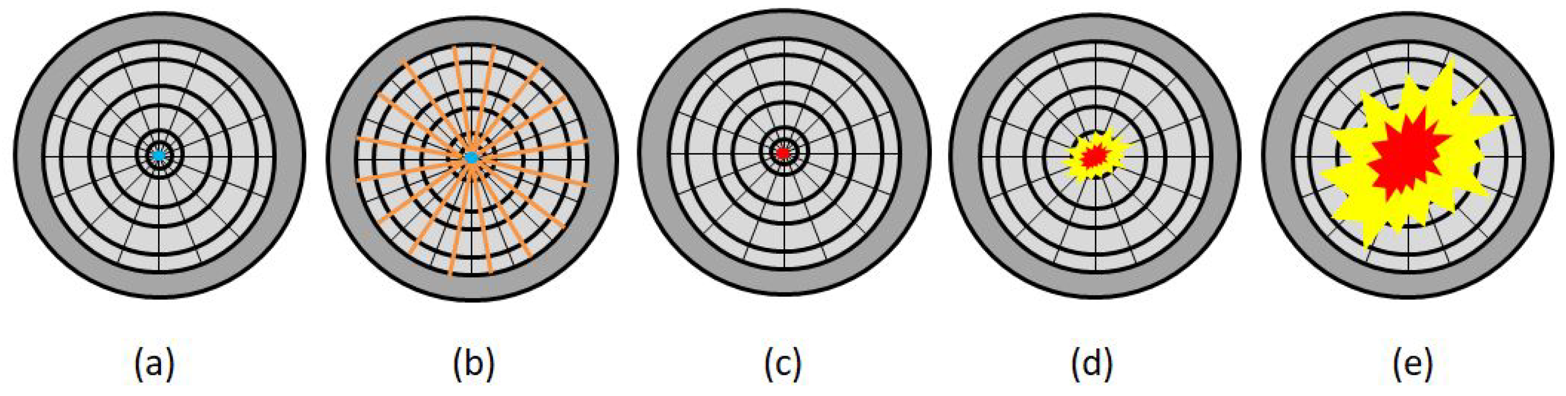
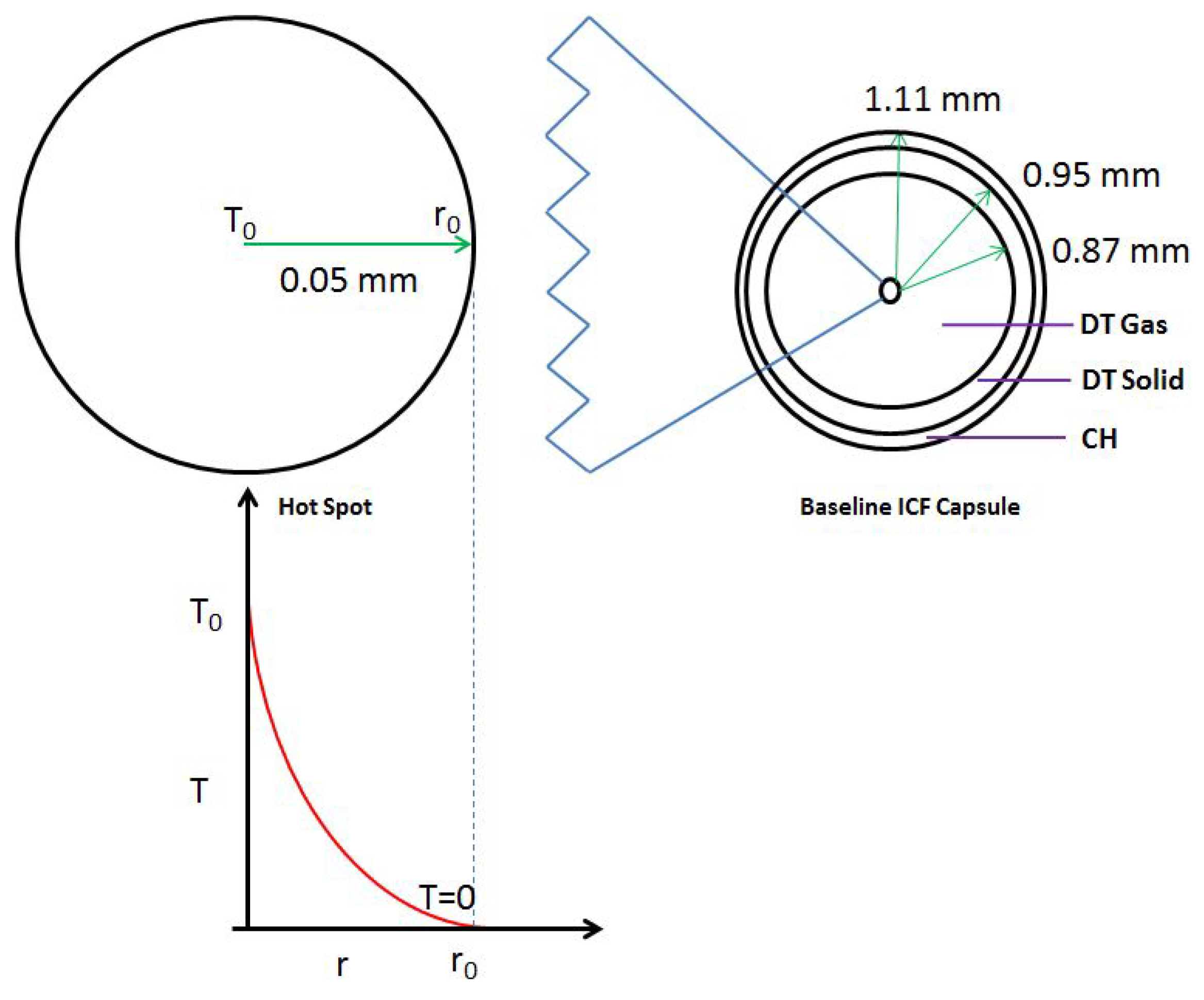

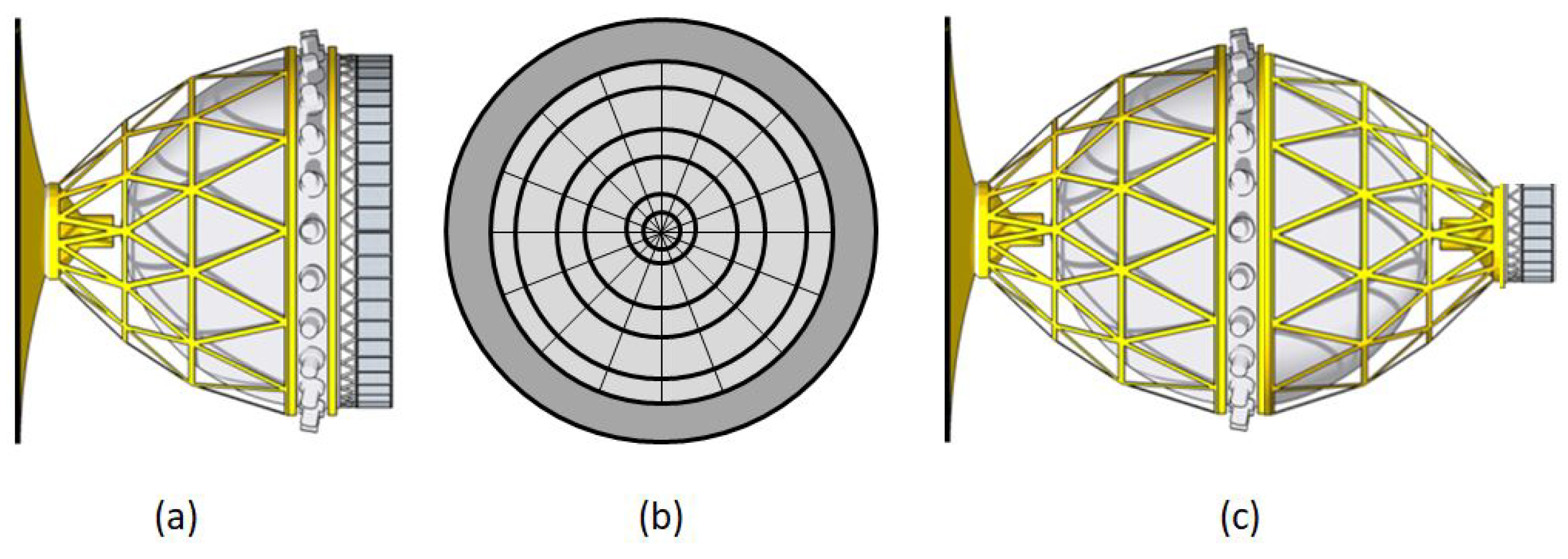

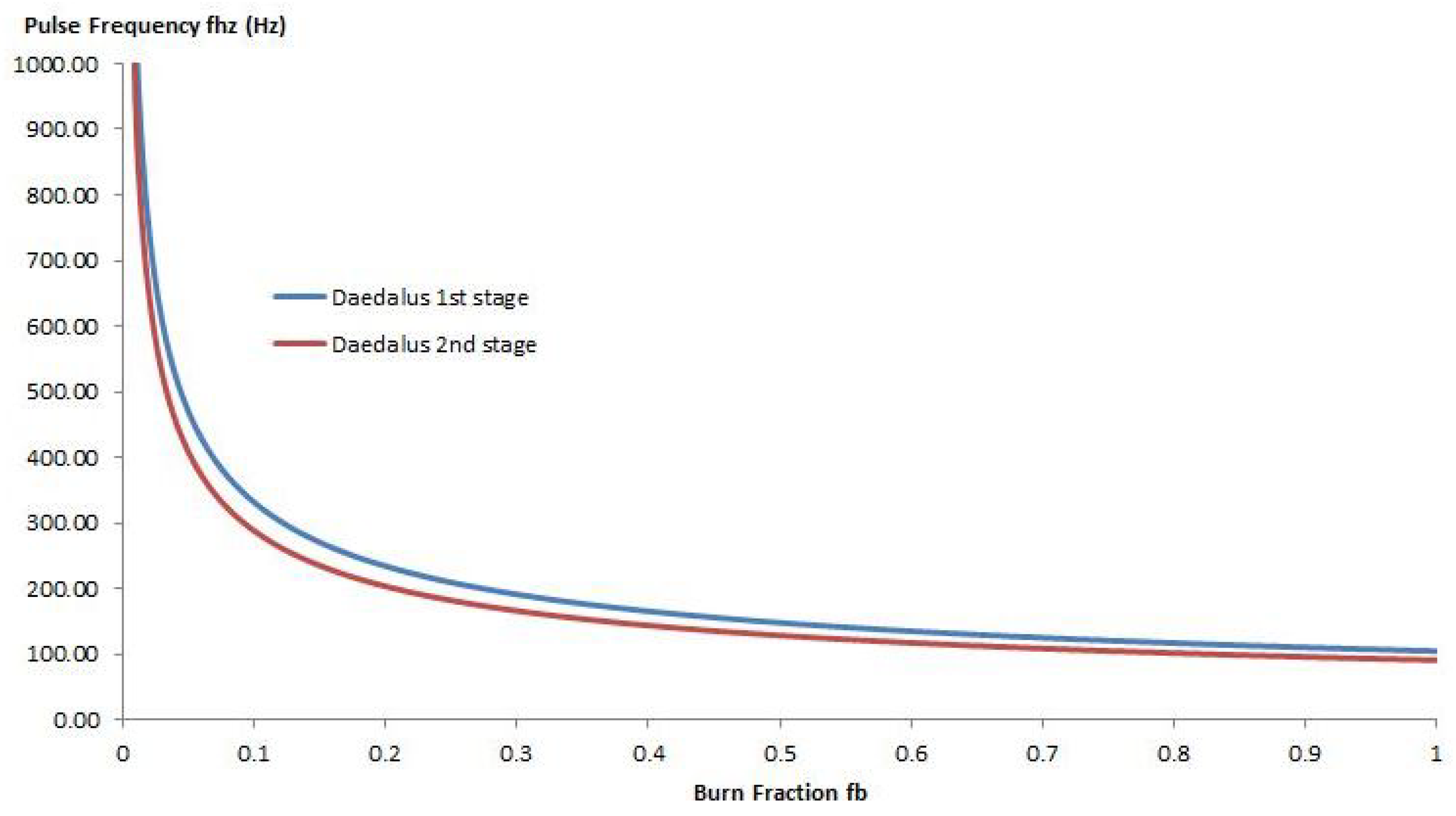
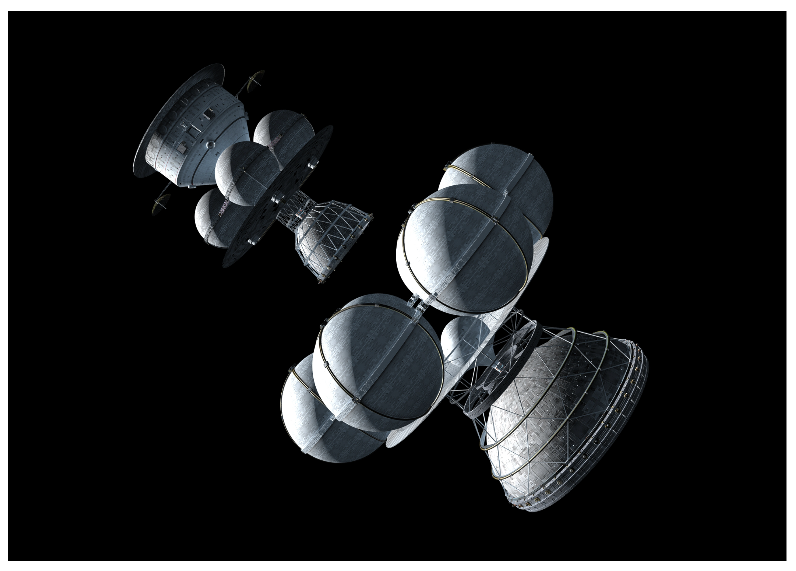


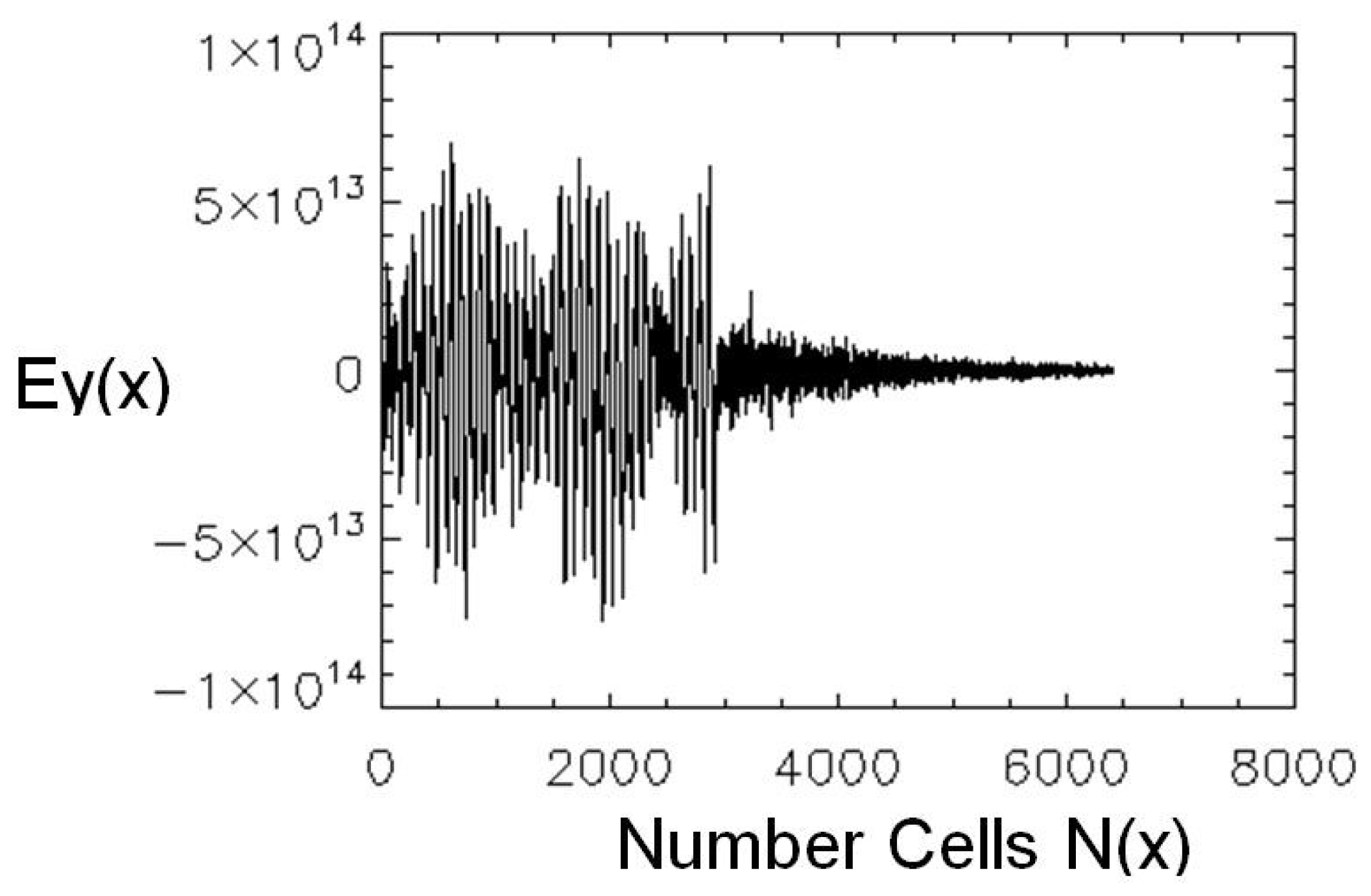
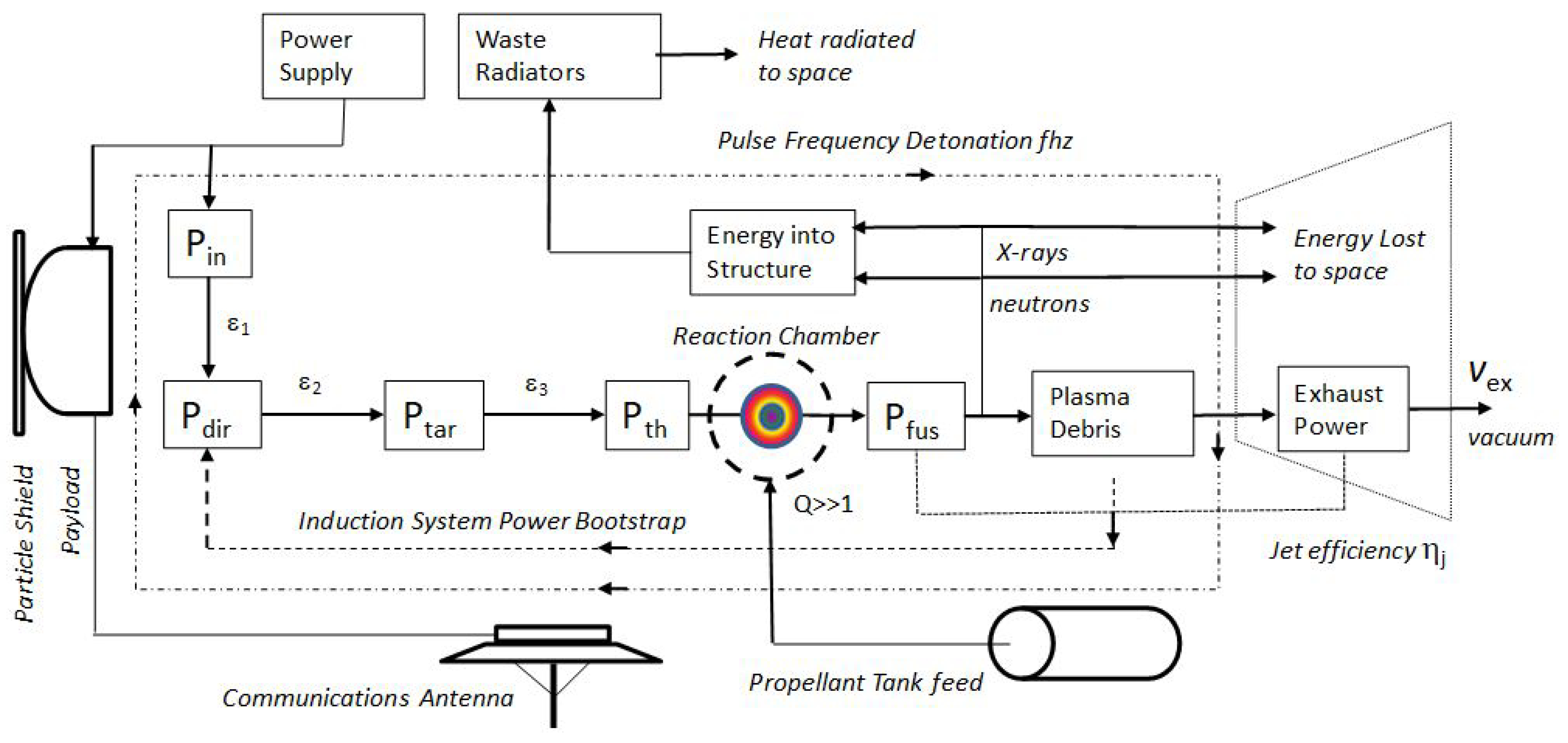
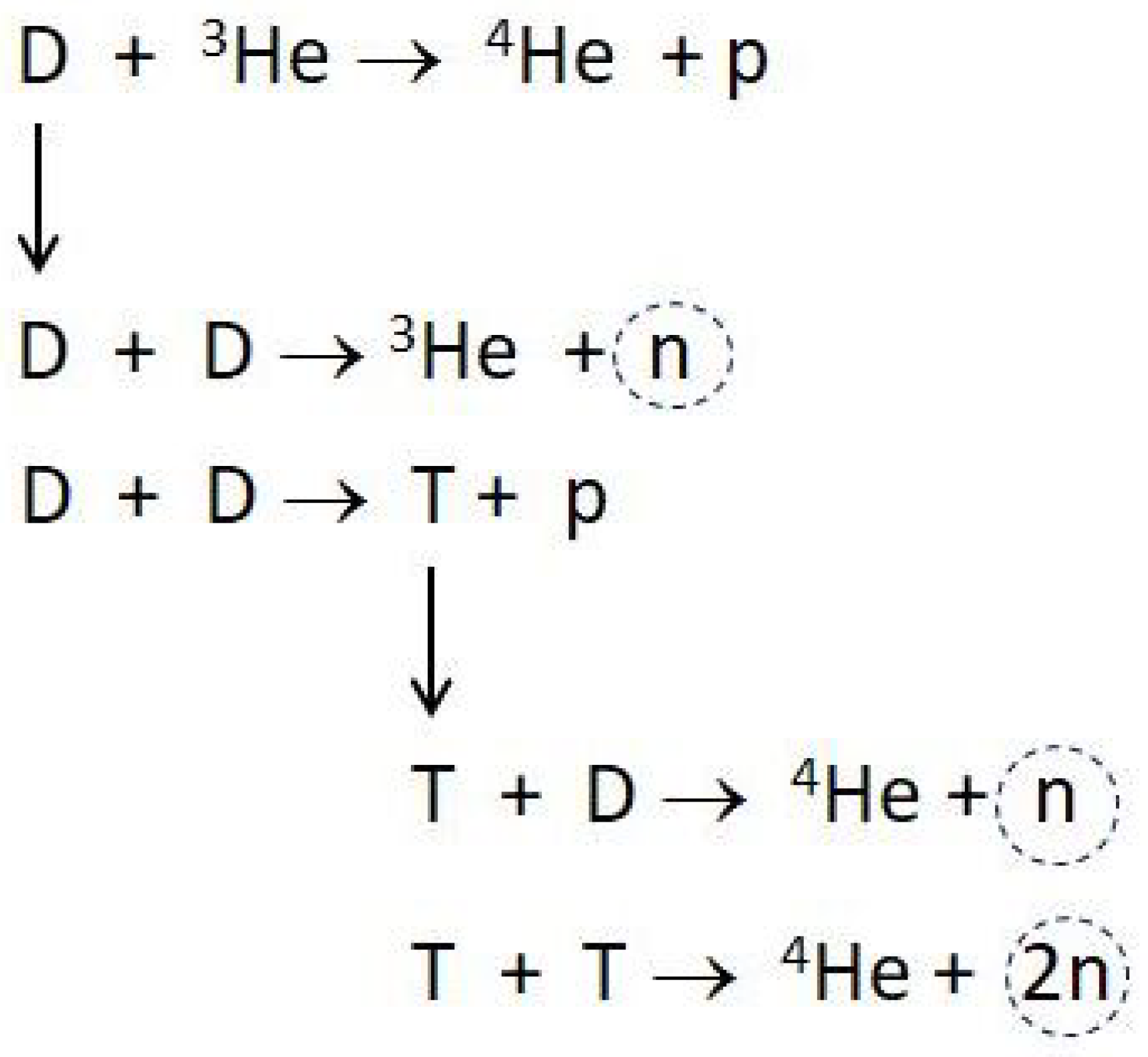
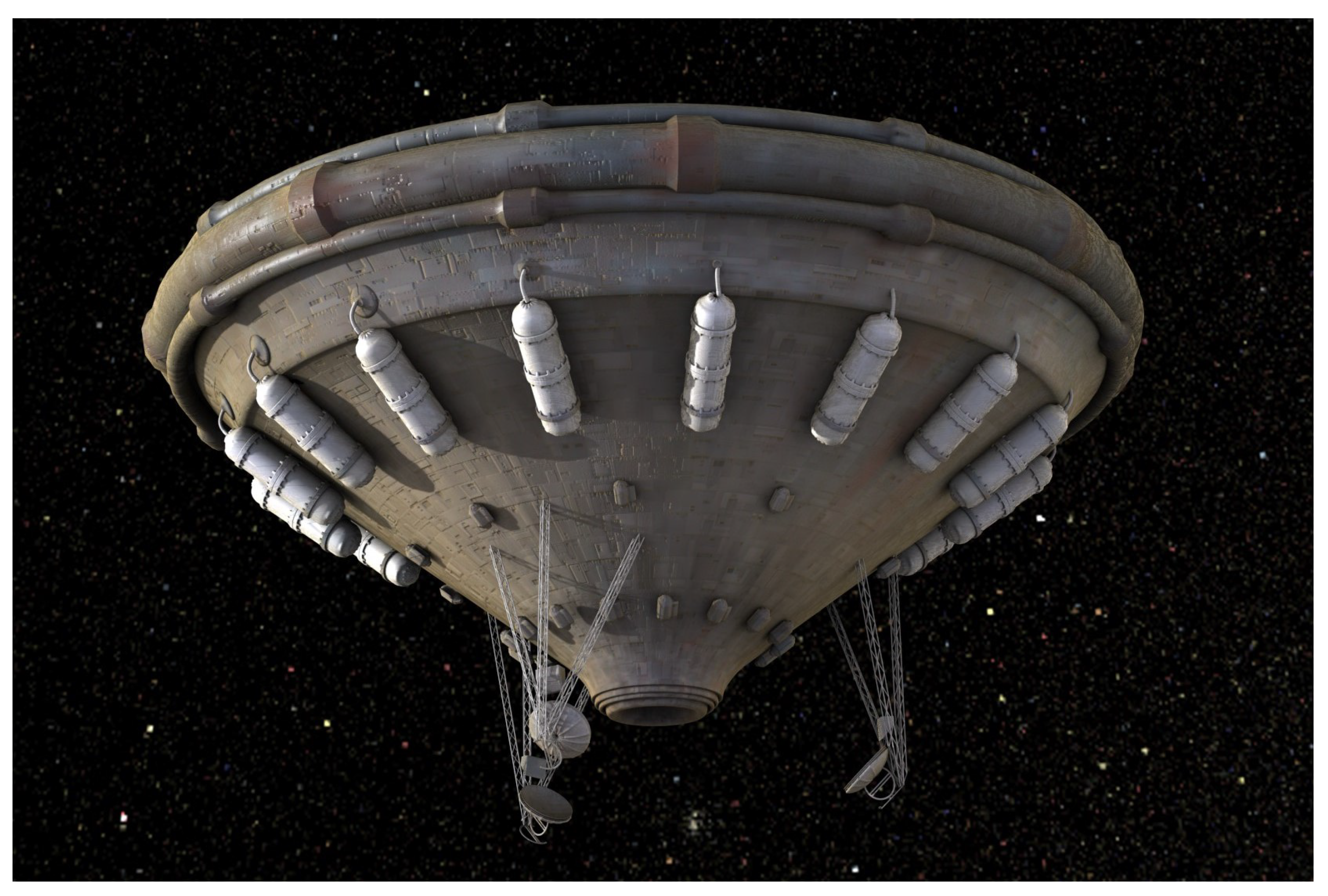
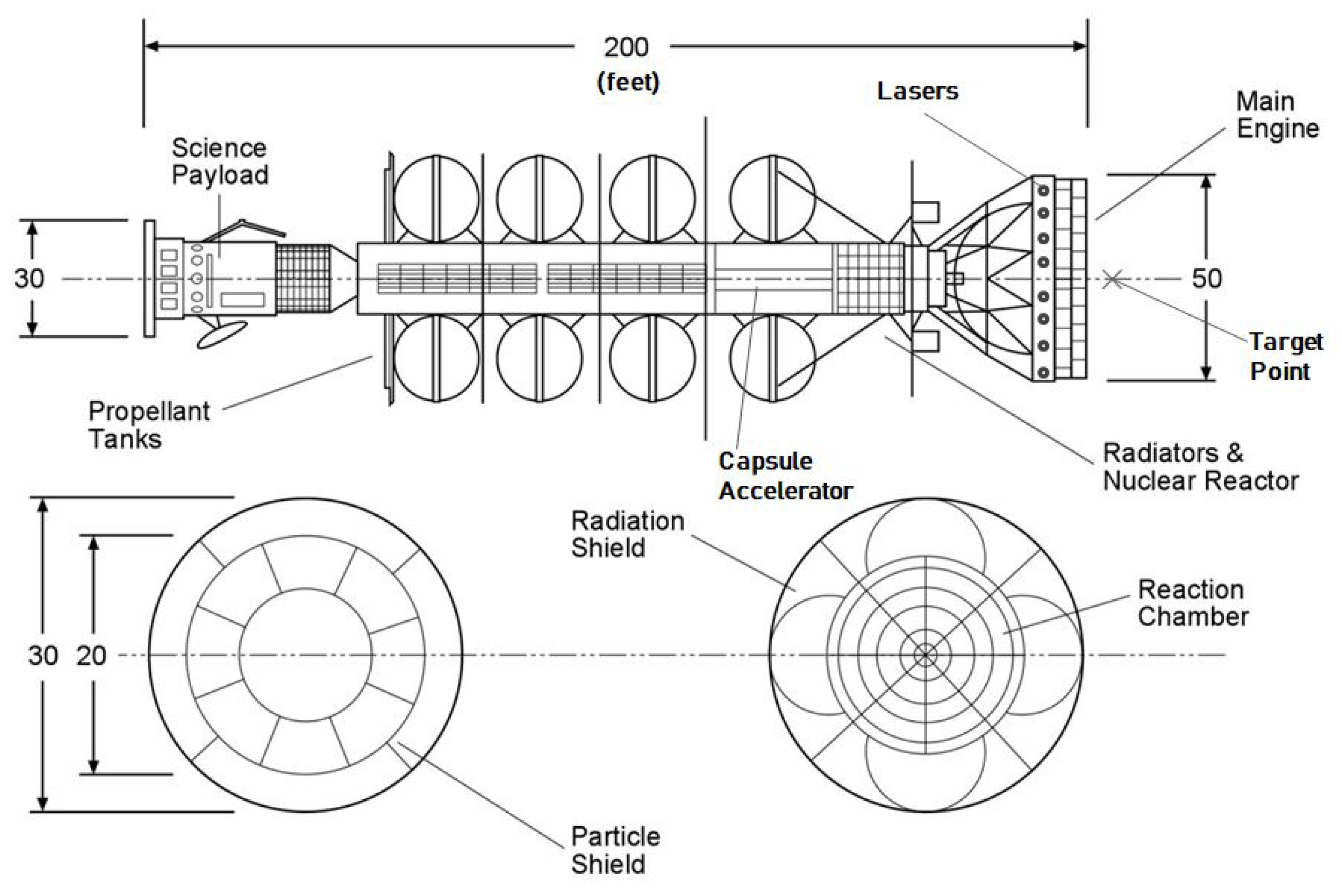
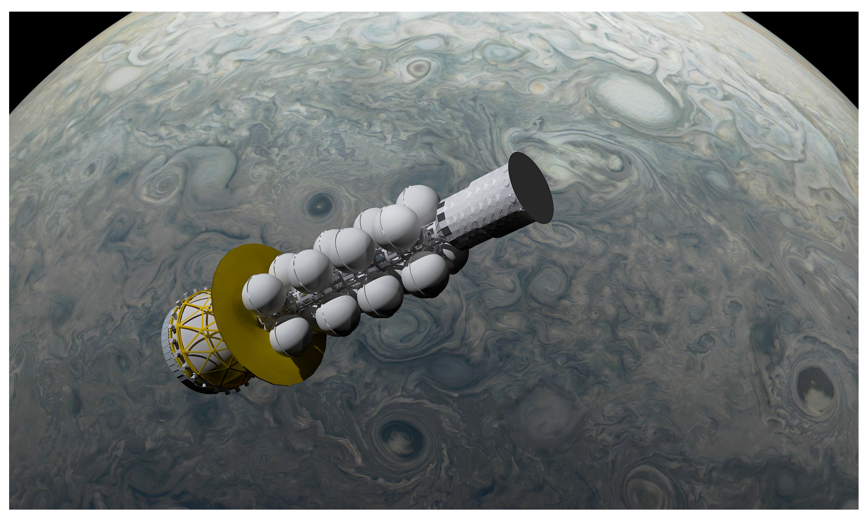