Abstract
K-EUSO (KLYPVE-EUSO) is a planned orbital mission aimed at studying ultra-high energy cosmic rays (UHECRs) by detecting fluorescence and Cherenkov light emitted by extensive air showers in the nocturnal atmosphere of Earth in the ultraviolet (UV) range. The observatory is being developed within the JEM-EUSO collaboration and is planned to be deployed on the International Space Station after 2025 and operated for at least two years. The telescope, consisting of independent pixels, will allow a spatial resolution of ∼0.6 km on the ground, and, from a 400 km altitude, it will achieve a large and full sky exposure to sample the highest energy range of the UHECR spectrum. We provide a comprehensive review of the current status of the development of the K-EUSO experiment, paying special attention to its hardware parts and expected performance. We demonstrate how results of the K-EUSO mission can complement the achievements of the existing ground-based experiments and push forward the intriguing studies of ultra-high energy cosmic rays, as well as bring new knowledge about other phenomena manifesting themselves in the atmosphere in the UV range.
1. Introduction
It was back in 1961 that cosmic rays with energies ≳50 EeV—henceforth called ultra-high energy cosmic rays (UHECRs)—were first registered [1]. However, the nature and origin of these most energetic particles in the Universe still remains a puzzle. One of the main difficulties in UHECR studies is their extremely low flux, of the order of a few particles per km sr per century. This requires the construction of huge experimental facilities able to collect sufficient statistics. For example, the array of surface detectors of the world’s largest cosmic ray observatory, the Pierre Auger Observatory (Auger), extends over an area of 3000 km [2]. Surface detectors of the second largest experiment, the Telescope Array (TA), occupy an area around 700 km, and the array is being expanded to cover an area approximately equal to that of Auger [3]. Both experiments employ a so-called hybrid technique for registering cosmic rays, complementing surface detectors with stations of fluorescence telescopes that observe ultraviolet emission of extensive air showers (EASs) developing in the nocturnal atmosphere. A great wealth of data has been obtained in the two experiments through the years, but the nature and origin of UHECRs still remains an open question. Furthermore, the results of Auger and TA related to the energy spectrum of cosmic rays at the highest energies show differences that could partly be ascribed to systematic uncertainties between the two observatories, but might also have a different origin, such as statistical fluctuations or even the effect of a powerful source in the northern hemisphere [4,5,6,7,8,9]. The fact that the fields of view of Auger and TA only partially overlap makes it difficult to cross-check the results to a full extent.
A revolutionary approach for studying UHECRs was put forward in 1981 [10]. By that time, registering fluorescence emission of EASs was already an established technique for studying UHECRs [11,12,13]. Benson and Linsley suggested placing a wide-field-of-view telescope with a mirror 36 m in diameter and a ∼5000-pixel retina in a low-Earth orbit (500–600 km), thus drastically increasing the exposure of the experiment and providing an opportunity to study cosmic rays arriving from the whole celestial sphere. Besides fluorescence, an orbital telescope is able to register forward-beamed Cherenkov radiation reflected from the Earth’s surface or from dense cloud tops, providing important additional information about the development of an EAS. A number of projects aiming to implement the idea have been suggested since then: among them, Orbiting Wide-field Light collectors (OWL) [14], Tracking Ultraviolet Setup (TUS) and KLYPVE [15,16], Joint Experiment Missions for Extreme Universe Space Observatory JEM-EUSO (formerly Extreme Universe Space Observatory on board the Japanese Experiment Module) [17], Probe Of Extreme Multi-Messenger Astrophysics (POEMMA) [18] and others. TUS was the first one launched into space on 28th April, 2016. It was a telescope with a Fresnel mirror of 2 m and a focal surface consisting of 256 pixels designed as a prototype of the KLYPVE project and mostly aimed at verifying the possibility of registering faint UV signals in the nocturnal atmosphere with an orbital telescope [19].
The TUS mission lasted from May, 2016, until the end of November, 2017. Unfortunately, 20% of the photomultiplier tubes (PMTs) comprising the focal surface of the detector were destroyed during an accident on the very first day of the experiment, and the sensitivities of the remaining PMTs changed in comparison with pre-flight measurements. Nevertheless, TUS registered a vast variety of signals taking place in the nocturnal atmosphere of Earth in the UV range and demonstrated that a space detector with the primary goal of searching for UHECRs can be used as a multi-disciplinary instrument with a wide science reach and with unique sensitivity for those phenomena [20,21,22,23,24].
Mini-EUSO (Multiwavelength Imaging New Instrument for the Extreme Universe Space Observatory or “UV atmosphere” in the Russian Space Program) is a telescope operating on board the International Space Station (ISS) in the ultraviolet (UV) range with a field of view of ≃44 and a ground resolution of km. It was launched with the uncrewed Soyuz MS-14 on 22 August 2019. The first observations from the nadir-facing UV-transparent window in the Russian Zvezda module took place on 7 October 2019. Since then, it has been taking data periodically, with installations occurring every couple of weeks. The instrument is expected to operate for at least three years. Mini-EUSO has, so far, observed night UV emissions from the Earth of natural and artificial origin, thousands of meteor candidates and several transient luminous events—in particular, emissions of light and very low frequency perturbation from an electromagnetic pulse (ELVEs), which are observed as large ring-like upper atmospheric emissions that appear to be expanding at superluminal speed—among other observations and scientific objectives. For more details on the detector and the data gathered so far, see [25,26].
K-EUSO (KLYPVE-EUSO) is one of the key projects of the JEM-EUSO program [27]. It is the first mission in this framework that will be able to detect UHECRs from space. The project is included in the long-term program of experiments onboard the Russian segment of the ISS. It was planned to be launched in 2024. However, due to the complexity and high cost of the project, the possible launch date was shifted to around 2026. In what follows, we provide a comprehensive review of the project status, design and scientific capabilities. The design presented below is a strongly modified version of what was shown in [28,29]. It is developed to satisfy the size and weight constraints of the carrier and deployment capabilities of the Russian segment of the ISS and to reach optimized scientific goals.
2. Scientific Goals
The general scientific goals of the K-EUSO mission are similar to those of other projects of the JEM-EUSO collaboration [27,30]. The ultimate purpose of the experiment is to make a significant step towards revealing the nature and origin of UHECRs, the highest energy particles in the Universe. The key questions to answer are: what are UHECRs, what are their sources and what are their acceleration mechanisms?
The most obvious way to investigate the origin of the cosmic rays is the analysis of their arrival directions. A benefit of an orbital experiment is that it can register cosmic rays arriving from the whole celestial sphere. In case a telescope is placed on the International Space Station, the exposure can be almost uniform, provided the mission is sufficiently long [31]. This will make large-scale anisotropy analysis both more statistically powerful and more reliable by providing a larger significance for the same overall statistics and by eliminating the problem of merging datasets from different parts of the sky taken with different instruments, and therefore different resolutions and different systematics [32,33,34,35].
The arrival direction distribution as measured by Auger is characterized by a large scale dipole anisotropy pointing in the direction in the galactic coordinates [33]. Such a result is significant to over five sigma levels, supporting the extragalactic origin of cosmic rays above eV. On the intermediate scales, both TA [32] and Auger [36] show indications of an anisotropy; in the case of Auger, with some degree of correlation with classes of nearby sources. This makes it mostly important to measure the UHECR flux over the entire sky in a consistent way, similar to how an instrument in space would generally provide. K-EUSO would be able to make a major improvement in this respect by measuring dipole and quadrupole moments in the arrival direction distribution, which are affected by major uncertainties when performed by different arrays on ground [37]. In addition, K-EUSO will be able to test if there is a correlation between the arrival directions of UHECRs and the distribution of matter in the nearby Universe. It will also provide an opportunity to verify other hypotheses related to the anisotropy of UHECRs. In particular, after a year or two of operation in space, K-EUSO could provide sufficient data to identify the signature of a nearby source in the large-scale UHECR anisotropy [38]. Data will also provide some information about the mass composition, providing directly comparable measurements over the entire sky for the first time. In particular, even though the mass sensitivity of K-EUSO is limited, thanks to the high statistics of events, it will be possible to measure for the first time the depth of the maximum above ∼50 EeV using the fluorescence technique. Such a measurement is currently not feasible with ground-based arrays due to the limited duty cycle of the fluorescence telescopes.
Another key characteristic of UHECRs is their energy spectrum, which is of crucial importance for understanding their origin and acceleration mechanisms. A large amount of effort is being applied to such studies at the leading ground-based experiments; see, e.g., [4,5]. The spectra obtained at Auger and TA demonstrate a good agreement at energies below 10 EeV, except for a difference in the absolute energy scale, which is within the systematic uncertainties of the experiments. An even better agreement is reached in the common declination band. However, an important difference between the spectra is observed at the highest energies. Besides this, TA suggests different steepening positions for events arriving below and above declination , which may indicate a different energy spectrum in the northern hemisphere. On the other hand, no indication of the declination dependence has been found by Auger. With its full-sky coverage and comparatively large exposure, K-EUSO will provide data of the energy spectrum of UHECRs arriving from the whole celestial sphere, therefore giving a chance to clarify the reason for the different instances of steepening of the TA spectrum in the two declination bands and the origin of the systematic differences in the spectra of Auger and TA at energies above ∼50 EeV in the common declination band. We believe that these results will address some of the open questions of UHECR physics outlined in [39,40], especially those related to anisotropy studies and the energy spectrum.
Supplementary tasks of the K-EUSO mission are studies of transient luminous events in the atmosphere. In particular, as it was demonstrated by the TUS experiment, an orbital telescope is a perfect tool for observing ELVEs, which take place at heights of around 80–90 km. K-EUSO will also be able to shed new light on puzzling bright flashes registered by TUS far from thunderstorm regions and populated areas.
Besides this, the telescope will observe meteors, thereby providing additional information for comprehensive understanding of the dynamics of meteors in the Solar System. It will also be able to register or place new limits on the existence of nuclearites (hypothetical massive strange quark matter nuggets); see [22,41,42,43] for more details and in-depth discussions.
3. The Detector
K-EUSO is a mission led by the Russian Space Agency together with the international JEM-EUSO collaboration to place an UHECR observatory on board the Russian segment of the ISS. The concept of the detector is based on the mirror-type detector proposed at the Skobeltsyn Institute of Nuclear Physics of Lomonosov Moscow State University (SINP MSU) in 2001 [15]. It has passed several stages of improvements since then to meet both scientific requirements and technical feasibility. In 2010, the project was included in the long-term program of experiments onboard the Russian segment of the ISS. In 2012, SINP MSU finished the preliminary design stage of the K-EUSO telescope for UHECR measurements from the International Space Station. It was designed as a large 10 m mirror telescope with a focal distance of 3 m and a field of view (FOV) of about [44,45]. However, it became clear during the preliminary design phase that the parameters of the instrument (observation area and image quality) do not allow one to solve current problems in UHECR science due to a too small geometrical exposure. These considerations initiated the development of a new optical system for the KLYPVE detector in order to increase the FOV and to improve the spatial and angular resolution and the overall performance of the instrument. This work is performed in close cooperation with the JEM-EUSO collaboration since late 2013. To eliminate the off-axis aberration, an additional corrective Fresnel lens was introduced in front of the photodetector. Two versions of the detector were developed: the Baseline and Multi-Eye Telescope System (METS) [28,46]. These configurations were later transformed to a Schmidt telescope design [29].
Further feasibility studies demonstrated difficulties in the delivery and installation of the instrument outside the ISS. There were more than 30 separate parts for delivery, and assembling the telescope required many extra vehicular activities of astronauts. A decision was made to return to the version of purely lens optics based on the developments of the JEM-EUSO project [47], since it can provide optimal weight and size characteristics of the equipment.
In the latest configuration presented below, the detector consists of a refractive optical system with a rectangular aperture of ; see Figure 1. This size is due to the fact that each frame in the folded state should be smaller than mm and freely pass through the Progress cargo hatch. The optics comprises two optical elements (lenses) that focus the light onto a focal surface of size. The focal surface structure consists of 44 photodetector modules (PDMs) similar to those of the other JEM-EUSO missions, with a total amount of channels close to 10. The main parameters of the detector are given in Table 1. Spatial and temporal resolutions are, respectively, given by the ground-projected area observed by an individual channel (pixel) and the electronics gate time unit (GTU). More details about the detector substructures are provided in the following sections.
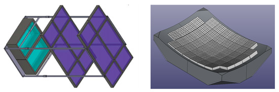
Figure 1.
(Left): a scheme of the K-EUSO detector with segmented refractive optics and rectangular aperture as designed by GP Advanced Project company. (Right): a 3D model of the K-EUSO focal surface built from 44 photo detector modules. It is to be placed inside the green “box” shown in the left panel.

Table 1.
Technical parameters of K-EUSO.
3.1. Optical System
Both optical elements of the telescope are made in the form of spherical Fresnel lenses manufactured from a special near-UV-transparent version of poly methyl methacrylate (PMMA) material. A significant optical power of such lenses is created by special annular zones of the Fresnel surface1, while, even with large dimensions, the thickness of the lenses turns out to be small, and the mass of the entire system is moderate. The PMMA-000 (Mitsubishi Chemical Corporation product) was chosen for several reasons. Along with a low density (approximately 1.2 g/cm), which ensures a low weight of lens, this material has a number of important optical properties, including a weak temperature dependence of the refractive index. The transparency of PMMA-000 practically does not change upon prolonged exposure to atomic oxygen (the main element of the residual atmosphere at the ISS altitude) and protons with an energy of approximately 70 MeV. At the same time, PMMA-000 is hard enough (in comparison, for example, to soft and plastic CYTOP) and can be used for high precision milling. To date, a number of lenses with similar characteristics of Fresnel concentric structures have already been manufactured: lenses for balloon experiments EUSO-Balloon [48] and EUSO-SPB1 [49], as well as for the space experiment Mini-EUSO [25].
The front lens is convex-concave, the rear one is concave-convex and all four radii of curvature are equal in absolute value, which greatly simplifies their production.
The optical power of the lenses is created by radial Fresnel structures, which are located on both surfaces of the front lens (S1 and S2) and on the front surface of the rear (S3). The calculation showed that, in order to ensure the quality of signal focusing in a wide spectral range (from 300 to 400 nm), the remaining surface (S4) must be a diffractive optical element (DOE).
The selection of the optimal values of the parameters of all four surfaces and the distances between the elements (lenses and focal surface) was carried out within the framework of numerical simulation in the Zemax OpticStudio2. Fresnel structures were modeled using the Zemax extended Fresnel surface with asphericity parameters up to the fourth degree in the square of the radial distance . The DOE was simulated as a binary optics 2 surface using the polynomial phase function up to the fifth degree on .
At the stage of preliminary modeling, the value of the radii of the curvature of all optical surfaces mm, as well as the concave spherical focal surface, mm, was chosen. The thickness of both lenses was fixed at 10 mm.
The RMS radius of the polychrome image (with the same weights for three main wavelengths, 337, 357 and 391 nm), averaged over the field of view from to , was chosen as an optimization criterion. The optical scheme and spot diagrams of the resulting system are shown in Figure 2.
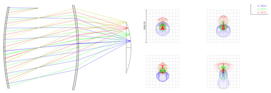
Figure 2.
(Left): K-EUSO optical scheme as sequential ray tracing (SRT) model in Zemax. (Right): spot diagrams for . The grid cell has a size of .
The system has a rectangular aperture of and the following axial distances: the distance between the lenses S2–S3 equals 2102 mm and the distance between the rear lens and the focal surface S4–FS equals 1466 mm. The total axial length of the system is mm; thus, the longitudinal dimension of the entire telescope, including the structure of the focal surface, does not exceed 4 m. The characteristic period of the diffraction grating at a distance of 1000 mm from the axis is 6 m and is acceptable from the point of view of manufacturing technology.
The Zemax sequential ray tracing (SRT) model provides an approximate estimate of the performance of the optical system. For a more accurate analysis that takes into account both scattering by Fresnel structures of optical surfaces and rectangular apertures of elements, the so-called non-sequential (NSRT) model is required. In this model, the Fresnel surfaces were chosen as annular zones of an equal depth of 2 mm. The total numbers of zones are 329 (S1), 391 (S2) and 364 (S3). To calculate the detector response, it is necessary to implement it within the simulator of the entire space experiment. Such models have been developed by the JEM-EUSO collaboration in the framework of the ESAF package (EUSO Simulation and Analysis Framework [50,51]). As a part of the calculations in ESAF, the consistency of the optics and electronics of the K-EUSO was checked (i.e., the comparison of the image size with the pixel size), as well as the calculation of the focusing efficiency and the effective light collection area (throughput).
A characteristic feature of Fresnel optics is that a part of the light energy is scattered at large angles relative to the centroid of the image. By the image, we mean here the part of it that falls into a box of size (i.e., K-EUSO pixels). Spot diagrams are presented in Figure 3 for different field angles . The quantitative dependence of the image size, understood as the RMS diameter in the spot box, in the entire field of view is presented in the third row of Table 2 (here, is the azimuth angle, and along small and large sides of the aperture, respectively). It can be seen that the optical system matches with a photodetector with a pixel of size mm up to . At larger angles, the asymmetry of the image becomes significant, which leads to a decrease in the efficiency of light collection.
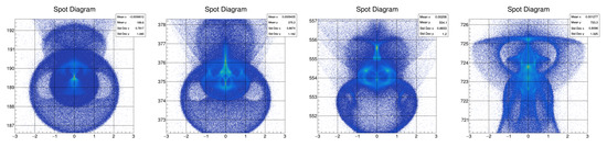
Figure 3.
Spot diagrams of the NSRT model for . Grid cell has a size of .
Table 2.
K-EUSO optics performance: image size , effective area and ensquared energy EE as a function of field angles , .
We estimated the efficiency of the optical system as the effective area , i.e., a ratio of the radiation energy in the image to the illumination of the entrance pupil, as well as ensquared energy (EE), the ratio of the energy in the pixel to that in the whole image. When calculating them, the effects of PMMA absorption, the reflection from four optical surfaces (including total internal reflection) and the scattering of rays due to hitting the lateral (cylindrical) sections of the Fresnel grooves were taken into account, and the diffraction efficiency of DOE was assumed to be 80%. The results are presented in the last two rows of Table 2.
Azimuthal asymmetry practically does not affect the position of the image: with a high degree of accuracy, the radial distance to the centroid is proportional to in the entire FOV up to 20, and the effective focal length is mm.
Based on the obtained results, it can be argued that this optical system of the telescope has the following characteristics:
- Field of view (with the optics matched to the sensor size): asymmetric with maximum field angle at , at , overall sr;
- Resolution: angular mrad , spatial km (at the orbit height km);
- Light collection area: geometric (at entrance pupil) m, effective m.
The manufacturing of the first (front) telescope lens began in late 2020. The calculated radial width of the Fresnel zones varies from 16 cm in the center to 1 mm at the periphery, with a groove depth of 2 mm. In view of the complexity of creating such a single one-piece large-sized structure, it was decided to arrange each of the lenses from six rectangular segments: four small ones, and two large ones, . Each of the segments were first given a spherical shape using two molds with a radius of curvature slightly larger than the calculated one; see Figure 4.
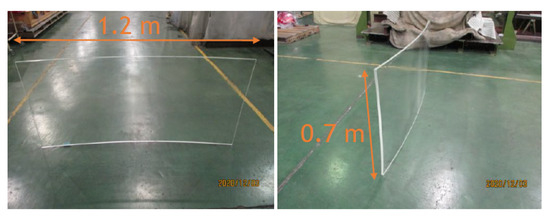
Figure 4.
PMMA samples after preliminary shaping.
The further manufacturing process included imparting the spherical lens to the calculated curvature, forming a radial Fresnel structure and polishing it. For this, a special fastening structure was realized, which made it possible to firmly attach curved plastic samples to it; see Figure 5. A Shibaura high-precision turning machine UTD34003 from RIKEN was used to make the Fresnel surfaces. At the first stage, the samples fixed to the structure were given a high-precision spherical shape with a calculated radius of curvature mm. Then, a radial Fresnel structure with a depth of 2 mm was applied to the surface (Figure 6) and the roughness was monitored. Measurements with Nanosurf Easyscan 2 AFM (an atomic force microscope) showed root mean square surface roughness nm.
Figure 5.
Lens shaping as a spherical surface of calculated curvature. In the left photo, one can see special jig construction in order to assemble the lens from segments.
Figure 6.
Formation and test of the Fresnel structure. (Left): the central segment of the lens. (Right): the measuring phase of the surface roughness.
The rear lens manufacturing will be finished by the end of March 2022, with the same quality as that of the front lens. The performance of the optics will be verified in 2022. A special laser scan system was manufactured at RIKEN for testing the quality of lenses. It was used earlier for testing the quality of the EUSO-SPB2 corrector lens [52]. We expect that the optics performance will meet the requirements.
3.2. Photodetector and the Central Processor Unit
The focal surface (FS) of the telescope is composed of 44 photodetector modules. The structure of the PDMs is similar to that of the JEM-EUSO telescope [47] and employs a modification of the digital data processing system (DDPS) developed previously for the Mini-EUSO mission [25]. The focal surface is a spherical concave surface with a 2 m radius of curvature, but constructed by flat PDMs. The structure of the FS is shown in the right panel of Figure 1.
Each PDM is a matrix of 36 Hamamatsu R11265-103-M64 Multi Anode Photomultipliers (MAPMTs). Each MAPMT consists of 64 independent channels (8 per side) with a 3 mm size. Each of these channels (identified as pixels in the following) has a field of view of 0.1, which corresponds to ∼600 m on the ground. The gate time unit (GTU) can vary from 1 s to 2.5 s, and will be determined as a trade-off between the limited hardware and telemetry budgets and the need for a good time resolution. Four MAPMTs are combined in elementary cells (EC-units) with a common high voltage Cockroft–Walton power supply.
The quantum efficiency of the MAPMTs is between 35–40% in the wavelength range of 300–400 nm. The photomultiplier signal is read out and amplified by the SPACIROC3 ASIC [53]. The SPACIROC3 operates in the single photoelectron mode and has a double pulse resolution of less than 10 ns. The majority of the data handling tasks, such as data buffering, configuration of the read-out ASICS, triggering, synchronization and interfacing with the central processor unit (CPU) system, is performed by the DDPS system. Given the very high time resolution of the detector (∼1 MHz) and the high number of pixels, no full data retrieval is possible. Data must therefore satisfy strict trigger conditions. Concentrations of the signal are sought for by the trigger algorithms to preferentially select the shower signal while rejecting background events; see Section 4.
The DDPS consists of one Zynq-board and three Cross boards. The output of the 36 ASICs of a PDM is collected by three Artix 7 FPGA-based Cross boards. The Cross boards perform data gathering from the ASICs and data multiplexing. The three Cross boards are connected to a Zynq board, containing a Xilinx Zynq 7000 FPGA with an embedded dual core ARM9 CPU processing system. The Zynq board controls the data flow from the ASICs, runs the trigger logics and interfaces with other PDMs and the CPU for data storage.
All PDMs of the FS operate independently and a special version of the modular photodetector and digital electronics for on-board signal processing are based on the network architecture principle. The network principle is implemented by organizing three types of links: high-speed communication between adjacent photodetector modules, long-haul communication for recording information in the CPU ROM and synchronizing communication for timing the operation of individual modules [54]. Digital processing, including the trigger system, is performed in a Zynq system-on-chip that includes the FPGA and the processor system. The two-level trigger system for EAS detection is used as was designed for the JEM-EUSO. For the registration of slower events, slower modes of operation are foreseen to be similar to the Mini-EUSO telescope. Triggers of the slow modes can be implemented in a processor part of FPGA since they do not need to be extremely fast.
A model of the PDM was made during the preliminary design stage of the project to confirm its performance characteristics and to check command and data transfer with the CPU. A photo of the PDM with DDPS and nine EC units during tests is shown in Figure 7. The modified EC unit with ASIC inside was developed especially for K-EUSO and EUSO-SPB2 projects in the Astroparticle and Cosmology laboratory (APC), France.
Figure 7.
K-EUSO electronics. Photo of an assembled PDM.
The absolute photometric calibration of the PDM was performed to study the overall efficiency of the photon detection. The photometric calibration provides a relationship between the amount of photons arriving at the detector and the measured signal. The methods suggested in [55] were employed for this purpose. At the first stage, the S-curves of all pixels were obtained to determine an optimal threshold of a single pulse detection.4 In K-EUSO, it is possible to adjust this threshold (the so-called DAC7 value) for each channel individually. A threshold is set in a minimum of a valley of a single photoelectron pulse distribution (between real photons and electronics noise). An example of an S-curve for one K-EUSO pixel and the corresponding single photoelectron pulse distribution are shown in Figure 8. The black vertical line in the right panel corresponds to the optimized threshold.
Figure 8.
(Left): S-curve of one K-EUSO photodetector pixel. (Right): Single photoelectron spectrum for the same pixel. Blue dots show experimental data, the red line is their fit and the black vertical line shows the optimal threshold. is the mean number of photoelectrons per GTU and DAC7 is a threshold set in SPACIROC for pulse discrimination.
Measurements with various incoming UV intensities were performed to obtain the dependence of the count rate on the number of photons. At the region of low intensities, this curve is linear, and then it begins to decline due to the pile-up effect. The curve allows us to obtain photon detection efficiency in a linear region, as well as an estimation of a dead time of photon counting determined by a SPACIROC3 operation. The map and distribution of channel efficiencies are shown in Figure 9. It can be seen that the efficiency of the majority of the pixels lies in the range of 20–40%. A number of border pixels have a higher noise due to their position near the border of the MAPMT. Therefore, their efficiency is overestimated, which can be seen in the pixel map. They have higher count rates and this should be taken into account in trigger algorithms because this can cause false triggers. (Pixel (1, 13) in this PDM is not functional.) The average value of the efficiency of the recording channels with preset individual thresholds for the registration of single-photoelectron pulses for the given EC-unit equals 34%.
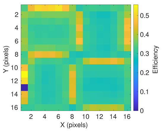
Figure 9.
Efficiency map for one EC unit. Colors denote estimated photon detection efficiency of individual pixels in fractions of 1, which corresponds to 100% efficiency.
The CPU is placed inside the ISS. The CPU consists of two subsets: the main one and the backup one. A cold standby scheme is provided, in which only one CPU subset works at a time. Both subsets of the CPU are implemented in one housing. Each CPU subset is designed on two printed circuit boards: a power supply board and a processor board.
The CPU power supply board contains a secondary power supply and a microcontroller. The microcontroller implements algorithms for the sequence of voltage supply to the processor board. In addition, the CPU microcontroller is the master device on the CAN bus, through which, commands are sent to turn on the components of the telescope and telemetry information is collected. The overall dimensions of the CPU are mm, which meets the requirements and allows it to be freely transported through the hatches of the ISS and the Progress cargo. It is equipped with two touch screens that allow astronauts to monitor the status of all K-EUSO subsystems and operate a manual control if necessary.
4. Expected Performance
In this section, estimations of the scientific performance of K-EUSO are presented following [56]. The study is based on intensive simulations with the ESAF framework [51] and their consequent analysis. The studies presented here must be regarded as preliminary since the configuration of the detector is still in the course of definition. However, both the trigger and reconstruction performance should be considered as indications of the observatory performance.
An example of the K-EUSO response to a UHECR simulated with ESAF is shown in Figure 10. The top panel demonstrates a distribution of photoelectrons from an EAS generated by a 100 EeV proton arriving at the zenith angle of (without any airglow emission taken into account) on the focal surface. The same photoelectrons are plotted as a function of time in the bottom left panel. A periodic decrease in the signal intensity is caused by the gaps between MAPMTs. The bottom right panel shows the wavelength spectrum of photons entering the detector. The fluorescence emission lines can be seen together with the continuum Cherenkov emission.
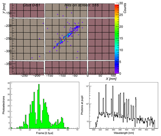
Figure 10.
Distribution of photoelectrons from an EAS generated by a 100 EeV proton arriving at the zenith angle of simulated with ESAF. Only signal from the shower is shown. (Top): distribution of the signal on the focal surface. (Bottom left): the corresponding time distribution of photoelectrons. (Bottom right): the spectrum of photons at the detector entrance.
4.1. Exposure
The trigger algorithms of the K-EUSO mission have been developed in the framework of the JEM-EUSO program [57] and are currently in the process of optimization. The results presented in the following are obtained directly using the scheme adopted for JEM-EUSO. The logic is structured in a number of stages, each reducing the trigger rate by several orders of magnitude. The first level trigger, to be operated at the level of the PDM, looks for concentrations of the signal localized in space and time. An excess of signal is required in cells of pixels integrated over five consecutive GTUs. Thresholds are set to have a spurious trigger rate, due to nightglow fluctuations, below 10 Hz/PDM. The second level trigger is activated each time the first level trigger conditions are satisfied and integrates the signal intensity in a sequence of preset directions that cover the entire phase space. Every GTU, the detected counts are summed in blocks of pixels along the preset direction for a total of 15 consecutive GTUs around the location and GTU where the first trigger level has been activated. Whenever the integrated signal along a direction overcomes a preset threshold, the second level trigger is issued. The activation of the second level trigger starts the transmission and data storage procedure. The data acquisition is therefore stopped and data are either saved on a hard disk or sent to ground by telemetry. This way, the trigger reduces the data flow by several orders of magnitude. Thresholds at the second trigger level are set to have a rate of the trigger every few seconds at most due to nightglow fluctuations to make the data acquisition consistent with the telemetry budget. In the case of JEM-EUSO, these trigger conditions were satisfying a telemetry budget of 300 kbit/s. The lower number of K-EUSO PDMs would allow for a slightly higher trigger rate, assuming similar telemetry. The optimization of the trigger parameters (thresholds and number of integrated GTUs) will be carried out in future, when the project proceeds to the next development phases. The aim of this section is therefore to test the efficiency curve of the algorithm with respect to cosmic ray air showers.
The exposure calculation is based on a Monte Carlo simulation of the EASs of variable energy and direction. To avoid border effects, cosmic rays are injected in an area larger than the FOV of the detector. The ratio of the triggered over simulated events is then calculated for each energy bin. The solid angle from which cosmic rays arrive on the field of view is also included in the formula. The effects of the day–night cycle and moon phases are taken into account in , the astronomical duty cycle. The effects of clouds and artificial lights are taken into account by and , respectively. In this formula, we assumed = 0.2, and = 0.9, as estimated in [58]. The exposure is then calculated over time t, which is assumed to be 1 year in the following:
The yearly exposure as a function of energy is shown in Figure 11. It can be seen that K-EUSO achieves an exposure of ∼18,000 km sr per year at the plateau, which is reached at energies above 100 EeV (to be compared with 5000–7000 km sr per year of the Auger collaboration and the TA×4 of Telescope Array). The 50% efficiency is reached around 40 EeV. Assuming the Auger spectrum [6], the expected rate of UHECRs triggered by K-EUSO is estimated to be around 65 events/year above 50 EeV, including 4 events with energies above 100 EeV. For comparison, the Pierre Auger collaboration has detected, on average, ∼19 events per year above 50 EeV for the SD spectrum under 60 degrees.
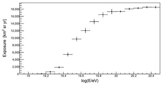
Figure 11.
Annual exposure of K-EUSO as a function of UHECR primary energy.
4.2. Angular Reconstruction
At the occurrence of a trigger, the acquisition is stopped and data are retrieved. The information collected at this point is then used to reconstruct parameters of the primary particle.
The first step consists of the recognition of the track, namely, of pixels and frames in which the light of the shower arrives. A comprehensive review of the signal identification methods is given in [59,60]. All of the methods look for concentrations of the signal in space and time that exhibit kinematics consistent with the presence of an extensive air shower.
The angular reconstruction extracts the arrival direction of the primary particle from the distribution and timing of the identified track. Several methods have been tested in the context of the JEM-EUSO program [59]. The method used for this work is based on a fit of the position and timing of the shower signal (the so-called Numerical Exact 1 method). In this method, the identification of the plane where both the shower and the detector lie is the first step of the procedure. The zenith angle of the shower is then reconstructed by comparing the arrival time of photons from a test shower and the identified track. The reconstruction performance for the arrival directions of EAS generated by 100 EeV protons arriving at zenith angles of and in the center of the field of view are shown in Figure 12. To assess the quality of the reconstruction, we plot the integral of the event distribution from 0 to a specific angle (in red). Here, 68% of the events fall within , proving an excellent reconstruction performance at the highest energies.
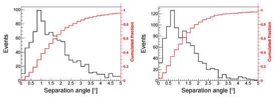
Figure 12.
Performance of the angular reconstruction for UHECRs with the energy 100 EeV in the center of the field of view. (Left): 45 zenith angle. (Right): 60 zenith angle.
In Figure 13, the angular resolution is plotted as the angle within which 68% of events fall. For this plot, we simulated 500 EASs in 16 different combinations of the energy and zenith angle. For each condition, the events were simulated over the entire field of view of the detector. It can be seen that K-EUSO will have a resolution between to for small zenith angles, but it improves to for nearly horizontal events. There is a clear improvement trend as the energy increases. For comparison, the Auger collaboration achieves an angular reconstruction better than 1 degree, whereas TA achieves a resolution of the same order.
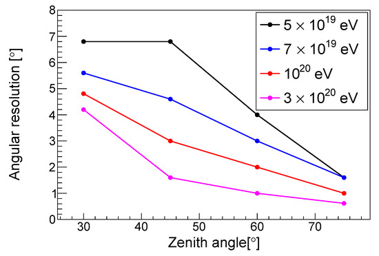
Figure 13.
Estimated angular resolution of K-EUSO for different zenith angles and energies of a primary particle in the full field of view of the detector.
4.3. Energy Reconstruction
The energy reconstruction is performed according to [60] and is based on the signal identified by pattern recognition. The photoelectron profile is reconstructed based on the counts falling in the identified track with the airglow subtracted on average. The attenuation occurring in the detector is corrected following a look-up table relating an incident direction and wavelength of photons to the detector efficiency. Several methods to reconstruct the shower geometry have been implemented and are discussed in [59]. With a determination of the position of the shower in the atmosphere, it is possible to calculate the amount of atmospheric extinction and the luminosity curve. Knowledge of the fluorescence yield is then used to reconstruct the charged particle profile of an EAS. Such a profile is then fit with a shower profile parameterization to obtain the energy and the depth of the maximum5.
Estimations of the energy resolution of K-EUSO for UHECRs with different energies arriving at various zenith angles are shown in Figure 14. The results were obtained with 2500 showers simulated at fixed energies and zenith angles, both for the center and for the full field of view of the detector. The resolution was estimated as the standard deviation of the distribution which can be well approximated by a Gaussian6. It can be seen that the energy resolution is around 25% at low zenith angles and improves up to around 15% for nearly horizontal events, with a small improvement trend towards higher energies. No significant decrease in the performance was observed for events simulated in the full field of view. For comparison, Auger has an energy resolution above eV of the order of 7%, whereas TA has 18% in the same energy range. The systematic uncertainties on the energy scale are 14% and 21% for Auger and TA, respectively. Two examples of reconstructed profiles of the signal from 100 EeV UHECRs arriving at the zenith angle of are shown in Figure 15 as black crosses. Fits of the shower parameterization are shown in red. The two showers are different in the location of the signal in the focal surface. The one shown in the left panel crosses fewer gaps between MAPMTs than that in the right panel, and the maximum of the profile has enough data points for an accurate reconstruction. As a result, we found for the shower in the left panel and for the one in the right panel.
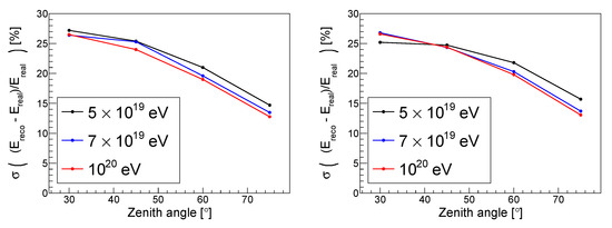
Figure 14.
Estimates of energy reconstruction for different energies and zenith angles. (Left): center of the field of view. (Right): full field of view of the detector.
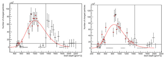
Figure 15.
Examples of reconstructed shower profiles as a function of slant depth. Both showers were generated by simulated 100 EeV UHECRs arriving at zenith angle. The red curves indicate shower profile fits. Red circles mark data points used for the reconstruction. Vertical black lines show boundaries of the interval selected for the reconstruction by the algorithm. Horizontal black segments correspond to gaps between PDMs and/or PMTs.
A totally different approach to the recognition of patterns produced by UV emission of EASs on the focal surface and to the reconstruction of parameters of primary UHECRs can be based on machine learning methods. A high efficiency of neural networks for identifying certain types of signals in the TUS data was demonstrated recently [61,62]. The first applications of neural networks to CR parameter reconstruction are also potentially interesting; see, e.g., [63,64,65]. A promising method of identifying EAS candidates in the data with the help of neural networks in real time has been developed for the EUSO-SPB2 mission [66]. The method will allow one to effectively suppress a big number of false positives, which is important in conditions of a limited telemetry budget. The procedure will be thoroughly tested during the flight that is planned to be performed in 2023 [67]. This approach will be examined during the future stages of development of the K-EUSO mission.
4.4. Depth of Maximum Reconstruction
A reconstruction of the depth of the maximum of an EAS is also performed according to [60] and is obtained from the fit of the reconstructed shower profile. A shower maximum can clearly be identified from the profiles shown in Figure 15. In this work, we only present a few examples of the reconstruction performance obtained in some specific condition. The method we use here considers only events where a Cherenkov reflection peak is visible. In this way, the impact point of the shower can be identified in the profile, and therefore a clear constraint can be put onto the shower geometry. For all of the other events, a more complex iterative study is needed and further work will be published in the future.
The resolution expressed as in units of g/cm is shown in Figure 16 for 200 EeV and for and in the left and right panels, respectively. The width of the distributions is around g/cm, whereas the mode of the distribution varies from approximately to . The reason for this systematic bias is being investigated and will be corrected once the detector configuration is defined completely. The long tails on the right side of the distributions are due to events impacting on the ground before the maximum is reached. The left tails are, on the other hand, due to events where the maximum is lost because of inter-PMT gaps. The former case is indeed more pronounced for vertical events, for which, the shower reaches the ground earlier in the shower development. A residual bias of the distribution is still visible and will be addressed in future publications. An overview of the performance in certain conditions is given in Table 3. The resolution is always around 50–90 g/cm for the center, and similar values are obtained for the whole field of view.
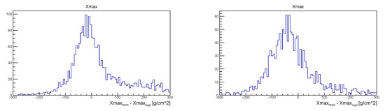
Figure 16.
Estimates of reconstruction for 200 EeV. (Left): zenith angle. (Right): zenith angle.
Table 3.
resolution of the K-EUSO detector in the center of the field of view.
These results should be regarded as preliminary, given the challenging nature of the reconstruction in monocular mode. Future studies will specifically address the reconstruction performance. For comparison, Auger achieves 15 g/cm above eV for the resolution and 10 g/cm for the systematic uncertainty. TA achieves, very similarly, 17 g/cm for the resolution and 17 g/cm for the systematic uncertainties.
5. Discussion and Conclusions
K-EUSO is an orbital telescope for studying UHECRs, and is planned to be deployed on the Russian segment of the International Space Station in the near future for a 2-year mission (or a longer mission if operations of the ISS are extended to 2030). With its latest design presented above, the instrument fits nicely in the Progress cargo and can be comparatively easily deployed outside the ISS. A number of the key elements of K-EUSO are already in production.
Despite the strongly reduced optical system, K-EUSO possesses technical parameters that are sufficient to make an important step in revealing the nature and origin of UHECRs. With the expected rate of triggered events of around 65 per year for energies above 50 EeV (assuming the Pierre Auger Observatory spectrum) and the energy resolution varying from 15% to 25% for different zenith angles, K-EUSO will allow us to verify certain results of Auger and the Telescope Array concerning the energy spectrum of cosmic rays at respective energies. With a sufficiently long mission, K-EUSO will provide an opportunity to test the dependence of the energy spectrum on the declination reported by the TA.
With its full-sky exposure, it will provide the first complete map of the sky in UHECRs obtained in a consistent way by one single instrument. The angular resolution of the telescope will be good enough to explore anisotropies at medium and large scales. Combined with high statistics of events, this will provide a chance to verify the existence of the hot spot observed by TA and the warm spot found by Auger, to look for a possible correlation between the arrival directions of UHECRs and the distribution of matter in the local Universe and to test if there are signatures of a nearby source contributing to the flux of CRs above ∼50 EeV in their large-scale anisotropy. Despite the large uncertainty on the depth of the shower maximum on individual events, the uncertainty on the average composition will be reduced by the statistics collected in each energy bin. Two energy bins could be envisaged: one around the threshold (i.e., eV) and the other at the highest energies (i.e., close to eV). Both would contain decent statistics and would be separated enough to account for effects related to the energy resolution [68]. Thus, the data will also provide some information about the mass composition of cosmic rays, which would allow for directly comparable measurements over the entire sky for the first time.
Being a multi-purpose instrument with a huge field of view, unique sensitivity and high temporal resolution, K-EUSO will be able to make interesting contributions to atmospheric sciences, especially in regard to transient luminous events, to meteor studies and to the search of hypothetical nuclearites, as was demonstrated by comprehensive simulations performed during the development of the JEM-EUSO telescope [41,69] and confirmed later with observations of TUS [21,22,24] and Mini-EUSO [26,70,71].
Author Contributions
Formal analysis, M.B. (Marta Bianciotto) and F.F.; Funding acquisition, P.K., M.B. (Mario Bertaina), C.F. and E.P.; Investigation, M.C., T.E., A.N., N.S., K.S. and Y.T.; Methodology, A.B., S.B.-B., W.M., G.P., S.S. and J.S.; Project administration, I.Y.; Software, M.B. (Matteo Battisti), A.B., M.B. (Marta Bianciotto), F.F., Z.P., M.P. and K.S.; Supervision, P.K., M.B. (Mario Bertaina), E.P. and P.P.; Validation, A.B., M.C., T.E., N.S., Y.T. and D.T.; Writing—original draft, P.K., F.F., S.S. and M.Z.; Writing—review & editing, P.K., M.B. (Mario Bertaina), C.F., E.P., Y.T. and M.Z. All authors have read and agreed to the published version of the manuscript.
Funding
This work was partially supported by the State Space Corporation ROSCOSMOS, by the Italian Ministry of Foreign Affairs and International Cooperation as a Project of Great Relevance between Italy and Japan, by JSPS KAKENHI Grant (JP19H01915) and by the French Space Agency, CNES. The Russian authors are supported by the Interdisciplinary Scientific and Educational School of Lomonosov Moscow State University “Fundamental and Applied Space Research”.
Data Availability Statement
Not applicable.
Acknowledgments
The program of studying UHECRs with orbital telescopes was pioneered in Russia by Boris Khrenov and Mikhail Panasyuk. Unfortunately, they passed away recently. Their impact on the development of the research program was profound and their scientific legacy is fully recognized by all their collaborators. The authors express their deep and collegial thanks to the entire JEM-EUSO program and all its individual members. The article was prepared based on research materials carried out in the space experiment “KLYPVE,” included in the long-term program of experiments on board the Russian segment of the ISS.
Conflicts of Interest
The authors declare no conflict of interest.
Notes
| 1 | https://en.wikipedia.org/wiki/Fresnel_lens, (accessed on 17 January 2022). |
| 2 | https://www.zemax.com/pages/opticstudio, (accessed on 13 December 2021). |
| 3 | https://www.shibaura-machine.co.jp/en/product/nano/lineup/utd/shiyo.html, (accessed on 13 December 2021). |
| 4 | An S-curve is a dependence of the ASIC count rate vs. threshold, so it is a cumulative distribution function of single photoelectron pulses. |
| 5 | The function used here is the so called Gaisser–Ilina–Linsley (GIL) function. Simulations are being updated to include more up to date parameterizations and MC shower simulators as well. |
| 6 | A residual bias of ∼10% is remaining in the distribution. The bias is still under investigation and will be corrected in the future. |
References
- Linsley, J.; Scarsi, L.; Rossi, B. Extremely Energetic Cosmic-Ray Event. Phys. Rev. Lett. 1961, 6, 485–487. [Google Scholar] [CrossRef]
- The Pierre Auger Collaboration. The Pierre Auger Cosmic Ray Observatory. Nucl. Instrum. Meth. A 2015, 798, 172–213. [Google Scholar] [CrossRef]
- Abbasi, R.; Abu-Zayyad, T.; Allen, M.; Arai, Y.; Arimura, R.; Barcikowski, E.; Belz, J.; Bergman, D.; Blake, S.; Cady, R.; et al. Current status and prospects of surface detector of the TAx4 experiment. In Proceedings of the 37th International Cosmic Ray Conference—PoS(ICRC2021), Berlin, Germany, 12–23 July 2021; Volume 395, p. 203. [Google Scholar] [CrossRef]
- Deligny, O. The energy spectrum of ultra-high energy cosmic rays measured at the Pierre Auger Observatory and at the Telescope Array. In Proceedings of the 36th International Cosmic Ray Conference—PoS(ICRC2019), Madison, WI, USA, 24 July–1 August 2019; Volume 258, p. 234. [Google Scholar] [CrossRef]
- Abbasi, R.; Abu-Zayyad, T.; Allen, M.; Arai, Y.; Arimura, R.; Barcikowski, E.; Belz, J.; Bergman, D.; Blake, S.; Cady, R.; et al. Joint analysis of the energy spectrum of ultra-high-energy cosmic rays as measured at the Pierre Auger Observatory and the Telescope Array. In Proceedings of the 37th International Cosmic Ray Conference—PoS(ICRC2021), Berlin, Germany, 12–23 July 2021; Volume 395, p. 337. [Google Scholar] [CrossRef]
- Aab, A.; Abreu, P.; Aglietta, M.; Albury, J.M.; Allekotte, I.; Almela, A.; Alvarez Castillo, J.; Alvarez-Muñiz, J.; Alves Batista, R.; Anastasi, G.A.; et al. Measurement of the cosmic-ray energy spectrum above 2.5×10¹⁸ eV using the Pierre Auger Observatory. Phys. Rev. D 2020, 102, 062005. [Google Scholar] [CrossRef]
- Hanlon, W. Telescope Array 10 Year Composition. In Proceedings of the 36th International Cosmic Ray Conference (ICRC2019), Madison, WI, USA, 24 July–1 August 2019; Volume 36, p. 280. [Google Scholar]
- Yushkov, A. Mass Composition of Cosmic Rays with Energies above 1017.2 eV from the Hybrid Data of the Pierre Auger Observatory. In Proceedings of the 36th International Cosmic Ray Conference (ICRC2019), Madison, WI, USA, 24 July–1 August 2019; Volume 36, p. 482. [Google Scholar] [CrossRef]
- di Matteo, A.; Anchordoqui, L.A.; Bister, T.; Biteau, J.; Caccianiga, L.; de Almeida, R.M.; Deligny, O.; Giaccari, U.; Harari, D.; Kim, J.; et al. UHECR arrival directions in the latest data from the original Auger and TA surface detectors and nearby galaxies. In Proceedings of the 37th International Cosmic Ray Conference—PoS(ICRC2021), Berlin, Germany, 12–23 July 2021; Volume 395, p. 308. [Google Scholar] [CrossRef]
- Benson, R.; Linsley, J. Satellite observation of cosmic ray air showers. In Proceedings of the 17th International Cosmic Ray Conference, Paris, France, 13–25 July 1981; Volume 8, pp. 145–148. [Google Scholar]
- Bunner, A.N. Cosmic Ray Detection by Atmospheric Fluorescence. Ph.D. Thesis, Cornell University, Ithaca, NY, USA, 1967. [Google Scholar]
- Mason, G.W.; Bergeson, H.E.; Cassiday, G.L.; Chiu, T.W.; Cooper, D.A.; Elbert, J.W.; Loh, E.C.; Steck, S.; West, W.J.; Boone, J.; et al. Observations of Extensive Air Showers by Air Fluorescence Description of Experimental Techniques. In Proceedings of the International Cosmic Ray Conference, Plovdiv, Bulgaria, 13–26 August 1977; Volume 8, p. 252. [Google Scholar]
- Cady, R.; Cassiday, G.L.; Elbert, J.; Loh, E.; Mizumoto, Y.; Sokolsky, P.; Steck, D.; Ye, M. The Fly’s Eye; American Institute of Physics Conference Series. AIP Conf. Proc. 1983, 96, 191–202. [Google Scholar] [CrossRef]
- Ormes, J.F.; Barbier, L.M.; Boyce, K.; Christian, E.; Krizmanic, J.F.; Mitchell, J.F.; Stecker, F.; Stilwell, D.E.; Streitmatter, R.E.; Chipman, R.A.; et al. Orbiting Wide-angle Light Collectors (OWL): A Pair of Earth Orbiting “Eyes” to Study Air Showers Initiated by >1020 eV Particles. In Proceedings of the International Cosmic Ray Conference, Durban, South Africa, 28 July–8 August 1997; Volume 5, p. 273. [Google Scholar]
- Khrenov, B.A.; Panasyuk, M.I.; Alexandrov, V.V.; Bugrov, D.I.; Cordero, A.; Garipov, G.K.; Linsley, J.; Martinez, O.; Salazar, H.; Saprykin, O.A.; et al. Space Program KOSMOTEPETL (project KLYPVE and TUS) for the study of extremely high energy cosmic rays. Observing Ultrahigh Energy Cosmic Rays from Space and Earth. AIP Conf. Proc. 2001, 566, 57–75. [Google Scholar] [CrossRef]
- Alexandrov, V.V.; Bugrov, D.I.; Garipov, G.K.; Grebenyuk, V.M.; Finger, M.; Khrenov, B.A.; Linsley, J.; Martinez, O.; Panasyuk, M.I.; Salazar, H.; et al. Space Experiment TUS For Study Of Ultra High Energy Cosmic Rays. Int. Cosm. Ray Conf. 2001, 2, 831. [Google Scholar]
- Adams, J.H.; Ahmad, S.; Albert, J.N.; Allard, D.; Anchordoqui, L.; Andreev, V.; Anzalone, A.; Arai, Y.; Asano, K.; Ave Pernas, M.; et al. The JEM-EUSO mission: An introduction. Exp. Astron. 2015, 40, 3–17. [Google Scholar] [CrossRef]
- Olinto, A.V.; Krizmanic, J.; Adams, J.H.; Aloisio, R.; Anchordoqui, L.A.; Anzalone, A.; Bagheri, M.; Barghini, D.; Battisti, M.; Bergman, D.R.; et al. The POEMMA (Probe of Extreme Multi-Messenger Astrophysics) observatory. J. Cosmol. Astropart. Phys. 2021, 06, 007. [Google Scholar] [CrossRef]
- Klimov, P.A.; Panasyuk, M.I.; Khrenov, B.A.; Garipov, G.K.; Kalmykov, N.N.; Petrov, V.L.; Sharakin, S.A.; Shirokov, A.V.; Yashin, I.V.; Zotov, M.Y.; et al. The TUS Detector of Extreme Energy Cosmic Rays on Board the Lomonosov Satellite. Space Sci. Rev. 2017, 212, 1687–1703. [Google Scholar] [CrossRef]
- Khrenov, B.A.; Klimov, P.A.; Panasyuk, M.I.; Sharakin, S.A.; Tkachev, L.G.; Zotov, M.Y.; Biktemerova, S.V.; Botvinko, A.A.; Chirskaya, N.P.; Eremeev, V.E.; et al. First results from the TUS orbital detector in the extensive air shower mode. J. Cosmol. Astropart. Phys. 2017, 9, 006. [Google Scholar] [CrossRef]
- Klimov, P.; Khrenov, B.; Kaznacheeva, M.; Garipov, G.; Panasyuk, M.; Petrov, V.; Sharakin, S.; Shirokov, A.; Yashin, I.; Zotov, M.; et al. Remote Sensing of the Atmosphere by the Ultraviolet Detector TUS Onboard the Lomonosov Satellite. Remote Sens. 2019, 11, 2449. [Google Scholar] [CrossRef]
- Shinozaki, K.; Montanaro, A.; Bertaina, M.E.; Fenu, F.; Ferrarese, S.; Klimov, P.; Sharakin, S.; Zotov, M.; Cellino, A.; Castellina, A.; et al. Search for nuclearites by the satellite-based TUS air fluorescence detector. In Proceedings of the 36th International Cosmic Ray Conference (ICRC2019), Madison, WI, USA, 24 July–1 August 2019; Volume 36, p. 545. [Google Scholar] [CrossRef]
- Khrenov, B.A.; Garipov, G.K.; Kaznacheeva, M.A.; Klimov, P.A.; Panasyuk, M.I.; Petrov, V.L.; Sharakin, S.A.; Shirokov, A.V.; Yashin, I.V.; Zotov, M.Y.; et al. An extensive-air-shower-like event registered with the TUS orbital detector. J. Cosmol. Astropart. Phys. 2020, 2020, 033. [Google Scholar] [CrossRef]
- Klimov, P.; Sharakin, S.; Zotov, M.; Bertaina, M.E.; Fenu, F. Main results of the TUS experiment on board the Lomonosov satellite. In Proceedings of the 37th International Cosmic Ray Conference—PoS(ICRC2021), Berlin, Germany, 12–23 July 2021; Volume 395, p. 316. [Google Scholar] [CrossRef]
- Capel, F.; Belov, A.; Casolino, M.; Klimov, P. Mini-EUSO: A high resolution detector for the study of terrestrial and cosmic UV emission from the International Space Station. Origins of Cosmic Rays. Adv. Space Res. 2018, 62, 2954–2965. [Google Scholar] [CrossRef]
- Bacholle, S.; Barrillon, P.; Battisti, M.; Belov, A.; Bertaina, M.; Bisconti, F.; Blaksley, C.; Blin-Bondil, S.; Cafagna, F.; Cambiè, G.; et al. Mini-EUSO Mission to Study Earth UV Emissions on board the ISS. Astrophys. J. Suppl. Ser. 2021, 253, 36. [Google Scholar] [CrossRef]
- Bertaina, M.E. An overview of the JEM-EUSO program and results. In Proceedings of the 37th International Cosmic Ray Conference—PoS(ICRC2021), Berlin, Germany, 12–23 July 2021; Volume 395, p. 406. [Google Scholar] [CrossRef]
- Panasyuk, M.; Klimov, P.; Khrenov, B.; Sharakin, S.; Zotov, M.; Picozza, P.; Casolino, M.; Ebisuzaki, T.; Gorodetzky, P. Ultra high energy cosmic ray detector KLYPVE on board the Russian Segment of the ISS. In Proceedings of the 34th International Cosmic Ray Conference —PoS(ICRC2015), Hague, The Netherlands, 30 July–6 August 2015; Volume 236, p. 669. [Google Scholar] [CrossRef]
- Klimov, P.; Casolino, M. Status of the KLYPVE-EUSO detector for EECR study on board the ISS. In Proceedings of the 35th International Cosmic Ray Conference (ICRC2017), Busan, Korea, 12–20 July 2017; Volume 301, p. 412. [Google Scholar] [CrossRef]
- Bertaina, M.E. Search for Ultra-High Energy Cosmic Rays from Space—The JEM-EUSO Program. In Proceedings of the 36th International Cosmic Ray Conference—PoS(ICRC2019), Madison, WI, USA, 24 July–1 August 2019; Volume 358, p. 192. [Google Scholar] [CrossRef]
- Adams, J.H., Jr.; Ahmad, S.; Albert, J.N.; Allard, D.; Anchordoqui, L.; Andreev, V.; Anzalone, A.; Arai, Y.; Asano, K.; Ave Pernas, M.; et al. JEM-EUSO observational technique and exposure. Exp. Astron. 2015, 40, 117–134. [Google Scholar] [CrossRef]
- Abbasi, R.U.; Abe, M.; Abu-Zayyad, T.; Allen, M.; Anderson, R.; Azuma, R.; Barcikowski, E.; Belz, J.W.; Bergman, D.R.; Blake, S.A.; et al. Indications of Intermediate-scale Anisotropy of Cosmic Rays with Energy Greater Than 57 EeV in the Northern Sky Measured with the Surface Detector of the Telescope Array Experiment. Astrophys. J. Lett. 2014, 790, L21. [Google Scholar] [CrossRef]
- Aab, A.; Abreu, P.; Aglietta, M.; Samarai, I.A.; Albuquerque, I.F.M.; Allekotte, I.; Almela, A.; Alvarez Castillo, J.; Alvarez-Muñiz, J.; Anastasi, G.A.; et al. Observation of a large-scale anisotropy in the arrival directions of cosmic rays above 8×10¹⁸ eV. Science 2017, 357, 1266–1270. [Google Scholar] [CrossRef]
- di Matteo, A.; Bister, T.; Biteau, J.; Caccianiga, L.; Deligny, O.; Fujii, T.; Harari, D.; Ivanov, D.; Kawata, K.; Lundquist, J.P.; et al. Full-sky searches for anisotropies in UHECR arrival directions with the Pierre Auger Observatory and the Telescope Array. In Proceedings of the 36th International Cosmic Ray Conference—PoS(ICRC2019), Madison, WI, USA, 24 July–1 August 2019; Volume 358, p. 439. [Google Scholar] [CrossRef]
- Kim, J.; Ivanov, D.; Kawata, K.; Sagawa, H.; Thomson, G. Hotspot Update, and a new Excess of Events on the Sky Seen by the Telescope Array Experiment. In Proceedings of the 37th International Cosmic Ray Conference—PoS(ICRC2021), Berlin, Germany, 12–23 July 2021; Volume 395, p. 328. [Google Scholar] [CrossRef]
- Aab, A.; Abreu, P.; Aglietta, M.; Albuquerque, I.F.M.; Allekotte, I.; Almela, A.; Alvarez Castillo, J.; Alvarez-Muñiz, J.; Anastasi, G.A.; Anchordoqui, L.; et al. An Indication of Anisotropy in Arrival Directions of Ultra-high-energy Cosmic Rays through Comparison to the Flux Pattern of Extragalactic Gamma-Ray Sources. Astrophys. J. 2018, 853, L29. [Google Scholar] [CrossRef]
- Tinyakov, P.; Anchordoqui, L.; Bister, T.; Biteau, J.; Caccianiga, L.; de Almeida, R.; Deligny, O.; di Matteo, A.; Giacari, U.; Harari, D.; et al. The UHECR dipole and quadrupole in the latest data from the original Auger and TA surface detectors. In Proceedings of the 37th International Cosmic Ray Conference—PoS(ICRC2021), Berlin, Germany, 12–23 July 2021; Volume 395, p. 375. [Google Scholar] [CrossRef]
- Kalashev, O.; Pshirkov, M.; Zotov, M. Identifying nearby sources of ultra-high-energy cosmic rays with deep learning. J. Cosmol. Astropart. Phys. 2020, 11, 5. [Google Scholar] [CrossRef]
- Dawson, B.R.; Fukushima, M.; Sokolsky, P. Past, Present and Future of UHECR Observations. Prog. Theor. Exp. Phys. 2017, 2017, 12A101. [Google Scholar] [CrossRef]
- Alves Batista, R.; Biteau, J.; Bustamante, M.; Dolag, K.; Engel, R.; Fang, K.; Kampert, K.H.; Kostunin, D.; Mostafa, M.; Murase, K.; et al. Open questions in cosmic-ray research at ultrahigh energies. Front. Astron. Space Sci. 2019, 6, 23. [Google Scholar] [CrossRef]
- Adams, J.H., Jr.; Ahmad, S.; Albert, J.N.; Allard, D.; Anchordoqui, L.; Andreev, V.; Anzalone, A.; Arai, Y.; Asano, K.; Ave Pernas, M.; et al. JEM-EUSO: Meteor and nuclearite observations. Exp. Astron. 2015, 40, 253–279. [Google Scholar] [CrossRef]
- Piotrowski, L.; Barghini, D.; Battisti, M.; Belov, A.S.; Bertaina, M.E.; Bisconti, F.; Blaksley, C.; Bolmgren, K.; Cafagna, F.; Cambiè, G.; et al. Towards observations of nuclearites in Mini-EUSO. In Proceedings of the 37th International Cosmic Ray Conference —PoS(ICRC2021), Berlin, Germany, 12–23 July 2021; Volume 395, p. 503. [Google Scholar] [CrossRef]
- Paul, T.C.; Reese, S.T.; Anchordoqui, L.A.; Olinto, A.V. EUSO-SPB2 sensitivity to macroscopic dark matter. In Proceedings of the 37th International Cosmic Ray Conference—PoS(ICRC2021), Berlin, Germany, 12–23 July 2021; Volume 395, p. 519. [Google Scholar] [CrossRef]
- Khrenov, B.A.; Alexandrov, V.V.; Bugrov, D.I.; Garipov, G.K.; Kalmykov, N.N.; Panasyuk, M.I.; Sharakin, S.A.; Silaev, A.A.; Yashin, I.V.; Grebenyuk, V.M.; et al. KLYPVE/TUS space experiments for study of ultrahigh-energy cosmic rays. Phys. At. Nucl. 2004, 67, 2058–2061. [Google Scholar] [CrossRef]
- Garipov, G.K.; Alexandrov, V.V.; Bugrov, D.I.; Cordero, A.; Cuautle, M.; Khrenov, B.A.; Linsley, J.; Martinez, O.; Moreno, E.B.; Panasyuk, M.I.; et al. Electronics for the KLYPVE Detector. AIP Conf. Proc. 2001, 566, 76–90. [Google Scholar] [CrossRef]
- Garipov, G.K.; Zotov, M.Y.; Klimov, P.A.; Panasyuk, M.I.; Saprykin, O.A.; Tkachev, L.G.; Sharakin, S.A.; Khrenov, B.A.; Yashin, I.V. The KLYPVE ultrahigh energy cosmic ray detector on board the ISS. Bull. Russ. Acad. Sci. Phys. 2015, 79, 326–328. [Google Scholar] [CrossRef]
- Adams, J.H.; Ahmad, S.; Albert, J.N.; Allard, D.; Anchordoqui, L.; Andreev, V.; Anzalone, A.; Arai, Y.; Asano, K.; Ave Pernas, M.; et al. The JEM-EUSO instrument. Exp. Astron. 2015, 40, 19–44. [Google Scholar] [CrossRef]
- Adams, J.H.; Ahmad, S.; Albert, J.N.; Allard, D.; Anchordoqui, L.; Andreev, V.; Anzalone, A.; Arai, Y.; Asano, K.; Ave Pernas, M.; et al. The EUSO-Balloon pathfinder. Exp. Astron. 2015, 40, 281–299. [Google Scholar] [CrossRef]
- Wiencke, L.; Olinto, A. EUSO-SPB1 Mission and Science. In Proceedings of the 35th International Cosmic Ray Conference—PoS(ICRC2017), Busan, Korea, 12–20 July 2017; Volume 301, p. 1097. [Google Scholar] [CrossRef]
- Berat, C.; Bottai, S.; De Marco, D.; Moreggia, S.; Naumov, D.; Pallavicini, M.; Pesce, R.; Petrolini, A.; Stutz, A.; Taddei, E.; et al. Full simulation of space-based extensive air showers detectors with ESAF. Astropart. Phys. 2010, 33, 221–247. [Google Scholar] [CrossRef]
- Fenu, F.; Shinozaki, K.; Miyamoto, H.; Liberatore, A.; Sakaki, N.; Sharakin, S.; Zotov, M.; Chiritoi, G. Simulations for the JEM-EUSO program with ESAF. In Proceedings of the 36th International Cosmic Ray Conference—PoS(ICRC2019), Madison, WI, USA, 24 July–1 August 2019; Volume 358, p. 252. [Google Scholar] [CrossRef]
- Kungel, V.; Bachman, R.; Brewster, J.; Dawes, M.; Desiato, J.; Eser, J.; Finch, W.; Huelett, L.; Olinto, A.V.; Pace, J.; et al. EUSO-SPB2 Telescope Optics and Testing. In Proceedings of the 37th International Cosmic Ray Conference—PoS(ICRC2021), Berlin, Germany, 12–23 July 2021; Volume 395, p. 412. [Google Scholar] [CrossRef]
- Blin-Bondil, S.; Dulucq, F.; Rabanal, J.; Dagoret-Campagne, S.; Tongbong, J.; Barrillon, P.; de La Taille, C.; Moretto, C.; Miyamoto, H.; Thienpont, D. SPACIROC3: A Front-End Readout ASIC for JEM-EUSO cosmic ray observatory. In Proceedings of the Technology and Instrumentation in Particle Physics 2014— PoS(TIPP2014), Amsterdam, The Netherlands, 2–6 June 2014; Volume 213, p. 172. [Google Scholar] [CrossRef]
- Belov, A.A.; Klimov, P.A.; Sharakin, S.A. The Network Architecture of the Data-processing System for the Photodetector of an Orbital Detector of Ultra-high Energy Cosmic Rays. Instruments Exp. Tech. 2018, 61, 27–33. [Google Scholar] [CrossRef]
- Adams, J.H.; Ahmad, S.; Albert, J.N.; Allard, D.; Anchordoqui, L.; Andreev, V.; Anzalone, A.; Arai, Y.; Asano, K.; Ave Pernas, M.; et al. Calibration aspects of the JEM-EUSO mission. Exp. Astron. 2015, 40, 91–116. [Google Scholar] [CrossRef]
- Fenu, F.; Sharakin, S.; Zotov, M.; Sakaki, N.; Takizawa, Y.; Bianciotto, M.; Bertaina, M.E.; Casolino, M.; Klimov, P. Expected performance of the K-EUSO space-based observatory. In Proceedings of the 37th International Cosmic Ray Conference—PoS(ICRC2021), Berlin, Germany, 12–23 July 2021; Volume 395, p. 409. [Google Scholar] [CrossRef]
- Abdellaoui, G.; Abe, S.; Acheli, A.; Adams, J.H.; Ahmad, S.; Ahriche, A.; Albert, J.N.; Allard, D.; Alonso, G.; Anchordoqui, L.; et al. Cosmic ray oriented performance studies for the JEM-EUSO first level trigger. Nucl. Instrum. Methods Phys. Res. A 2017, 866, 150–163. [Google Scholar] [CrossRef]
- Adams, J.H.; Ahmad, S.; Albert, J.N.; Allard, D.; Ambrosio, M.; Anchordoqui, L.; Anzalone, A.; Araia, Y.; Aramoo, C.; Asano, K.; et al. An evaluation of the exposure in nadir observation of the JEM-EUSO mission. Astropart. Phys. 2013, 44, 76–90. [Google Scholar] [CrossRef]
- Adams, J.H., Jr.; Ahmad, S.; Albert, J.N.; Allard, D.; Anchordoqui, L.; Andreev, V.; Anzalone, A.; Arai, Y.; Asano, K.; Ave Pernas, M.; et al. Performances of JEM-EUSO: Angular reconstruction. Exp. Astron. 2015, 40, 153–177. [Google Scholar] [CrossRef]
- Adams, J.H., Jr.; Ahmad, S.; Albert, J.N.; Allard, D.; Anchordoqui, L.; Andreev, V.; Anzalone, A.; Arai, Y.; Asano, K.; Ave Pernas, M.; et al. Performances of JEM–EUSO: Energy and Xmax reconstruction. Exp. Astron. 2015, 40, 183–214. [Google Scholar] [CrossRef]
- Zotov, M.Y.; Sokolinskiy, D.B. The First Application of Neural Networks to the Analysis of the TUS Orbital Detector Data. Mosc. Univ. Phys. Bull. 2020, 75, 657–664. [Google Scholar] [CrossRef]
- Zotov, M. Application of Neural Networks to Classification of Data of the TUS Orbital Telescope. Universe 2021, 7, 221. [Google Scholar] [CrossRef]
- Erdmann, M.; Glombitza, J.; Walz, D. A deep learning-based reconstruction of cosmic ray-induced air showers. Astropart. Phys. 2018, 97, 46–53. [Google Scholar] [CrossRef]
- Ivanov, D.; Kalashev, O.E.; Kuznetsov, M.Y.; Rubtsov, G.I.; Sako, T.; Tsunesada, Y.; Zhezher, Y.V. Using deep learning to enhance event geometry reconstruction for the Telescope Array surface detector. Mach. Learn. Sci. Tech. 2021, 2, 015006. [Google Scholar] [CrossRef]
- Aab, A.; Abreu, P.; Aglietta, M.; Albury, J.M.; Allekotte, I.; Almela, A.; Alvarez-Muñiz, J.; Batista, R.A.; Anastasi, G.A.; Anchordoqui, L.; et al. Deep-learning based reconstruction of the shower maximum Xmax using the water-Cherenkov detectors of the Pierre Auger Observatory. JINST 2021, 16, P07019. [Google Scholar] [CrossRef]
- Filippatos, G.; Battisti, M.; Bertaina, M.E.; Bisconti, F.; Eser, J.; Osteria, G.; Sarazin, F.; Wiencke, L. Expected Performance of the EUSO-SPB2 Fluorescence Telescope. In Proceedings of the 37th International Cosmic Ray Conference—PoS(ICRC2021), Berlin, Germany, 12–23 July 2021; Volume 395, p. 405. [Google Scholar] [CrossRef]
- Eser, J.; Olinto, A.V.; Wiencke, L. Science and mission status of EUSO-SPB2. In Proceedings of the 37th International Cosmic Ray Conference—PoS(ICRC2021), Berlin, Germany, 12–23 July 2021; Volume 395, p. 404. [Google Scholar] [CrossRef]
- Brümmel, V.; Engel, R.; Roth, M. On the importance of the energy resolution for identifying sources of UHECR. In Proceedings of the 33rd International Cosmic Ray Conference, Rio de Janeiro, Brazil, 2–9 July 2013; p. 0667. [Google Scholar]
- Adams, J.H., Jr.; Ahmad, S.; Albert, J.N.; Allard, D.; Anchordoqui, L.; Andreev, V.; Anzalone, A.; Arai, Y.; Asano, K.; Ave Pernas, M.; et al. Science of atmospheric phenomena with JEM-EUSO. Exp. Astron. 2015, 40, 239–251. [Google Scholar] [CrossRef]
- Marcelli, L.; Arnone, E.; Barghini, M.; Battisti, M.; Belov, A.S.; Bertaina, M.E.; Blaksley, C.; Bolmgren, K.; Cambiè, G.; Capel, F.; et al. Observation of ELVES with Mini-EUSO telescope on board the International Space Station. In Proceedings of the 37th International Cosmic Ray Conference—PoS(ICRC2021), Berlin, Germany, 12–23 July 2021; Volume 395, p. 367. [Google Scholar] [CrossRef]
- Golzio, A.; Battisti, M.; Bertaina, M.E.; Bolmgren, K.; Cambiè, G.; Casolino, M.; Cassardo, C.; Cremonini, R.; Ferrarese, S.; Fuglesang, C.; et al. A study on UV emission from clouds with Mini-EUSO. In Proceedings of the 37th International Cosmic Ray Conference —PoS(ICRC2021), Berlin, Germany, 12–23 July 2021; Volume 395, p. 208. [Google Scholar] [CrossRef]


Publisher’s Note: MDPI stays neutral with regard to jurisdictional claims in published maps and institutional affiliations. |
© 2022 by the authors. Licensee MDPI, Basel, Switzerland. This article is an open access article distributed under the terms and conditions of the Creative Commons Attribution (CC BY) license (https://creativecommons.org/licenses/by/4.0/).