
A Novel Mid-Infrared Narrowband Filter for Solar Telescopes

Abstract
1. Introduction
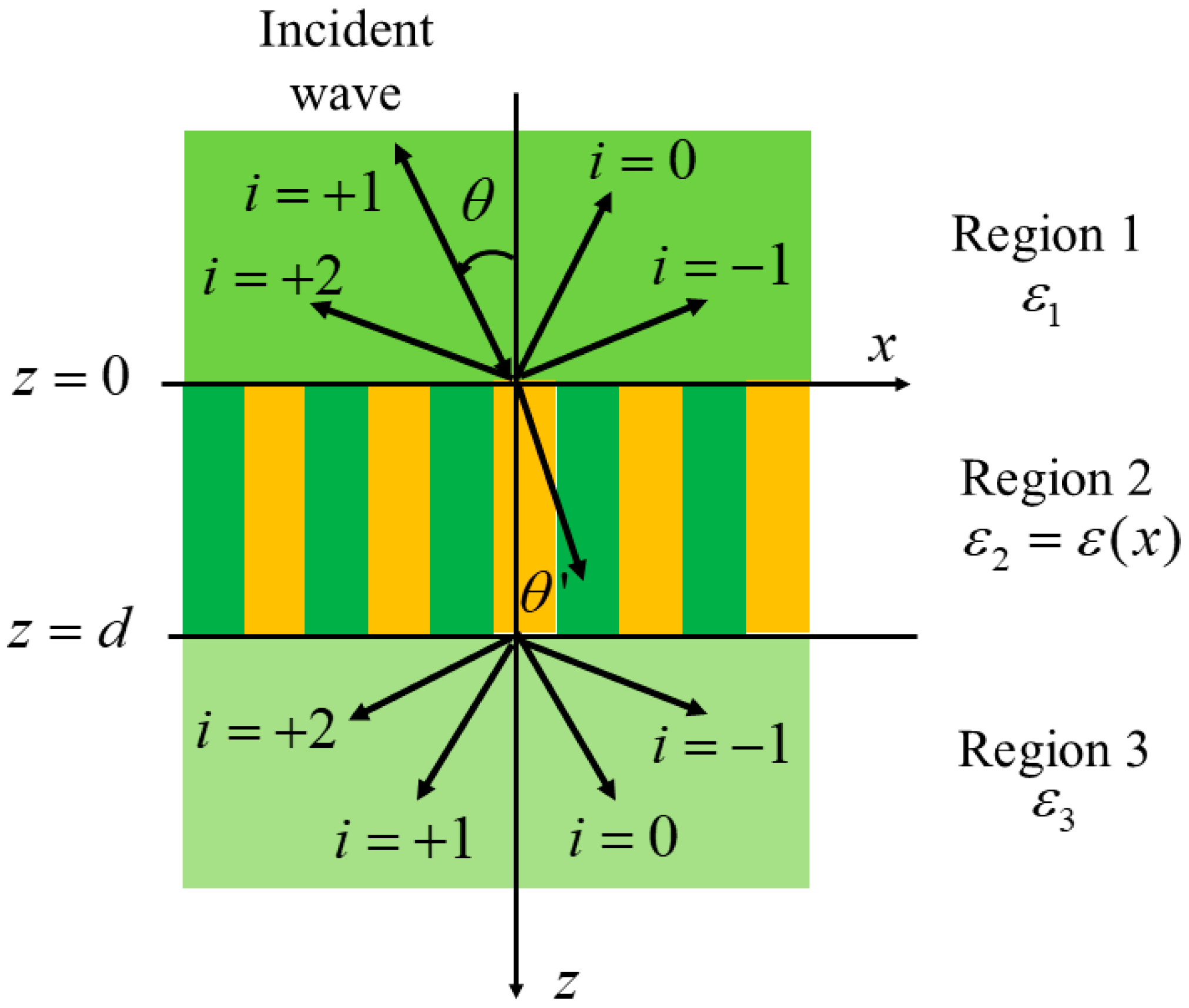
2. Theory
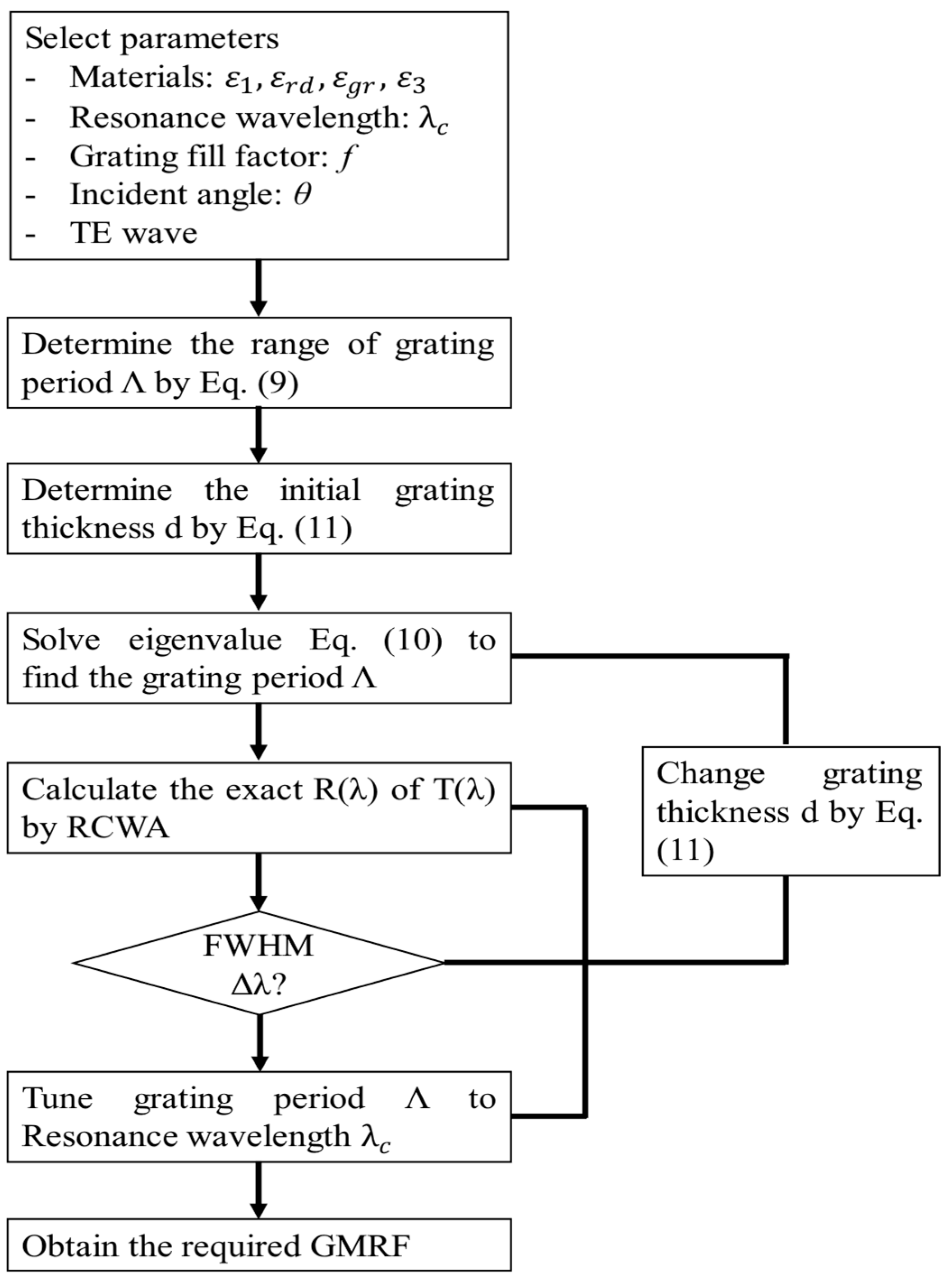
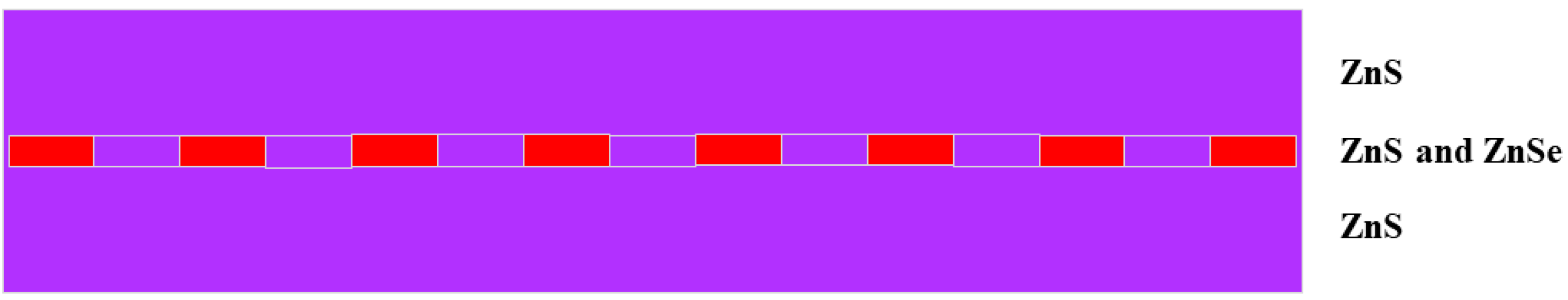
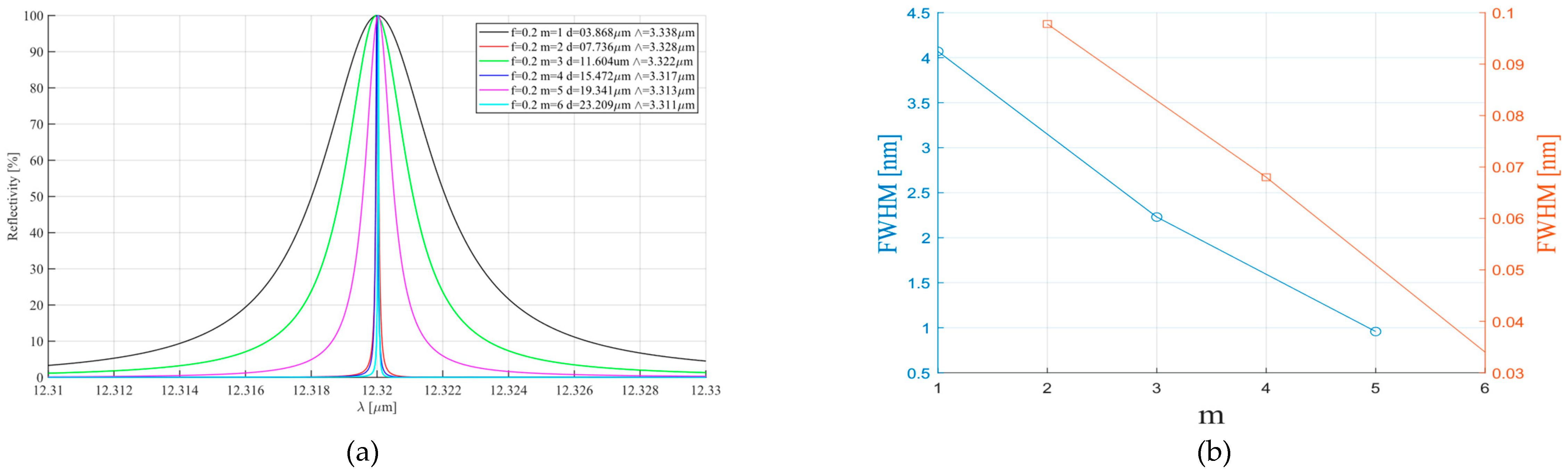
3. Preliminary Design and Simulation
4. Discussion and Conclusions
Funding
Institutional Review Board Statement
Informed Consent Statement
Data Availability Statement
Conflicts of Interest
References
- Zhang, Z.; Chen, D.Y.; Wu, J.; Chang, J.; Hu, Y.M.; Su, Y.; Zhang, Y.; Wang, J.P.; Liang, Y.M.; Ma, T.; et al. Hard X-ray Imager (HXI) onboard the ASO-S mission. Res. Astron. Astrophys. 2019, 19, 160. [Google Scholar] [CrossRef]
- Lemen, J.R.; Title, A.M.; Akin, D.J.; Boerner, P.F.; Chou, C.; Drake, J.F.; Duncan, D.W.; Edwards, C.G.; Friedlaender, F.M.; Heyman, G.F. The Atmospheric Imaging Assembly (AIA) on the Solar Dynamics Observatory (SDO). Sol. Phys. 2012, 275, 17–40. [Google Scholar] [CrossRef]
- Scherrer, P.H.; Schou, J.; Bush, R.I.; Kosovichev, A.G.; Bogart, R.S.; Hoeksema, J.T.; Liu, Y.; Duvall, T.L., Jr.; Zhao, J.; Title, A.M. The Helioseismic and Magnetic Imager (HMI) Investigation for the Solar Dynamics Observatory (SDO). Sol. Phys. 2012, 275, 207–227. [Google Scholar] [CrossRef]
- Meng, W.J.; Xu, F.Y.; Jin, Z.Y. New Vacuum Solar Telescope Achieves Narrowband Infrared Solar Imaging Observation at HeI 10830Å. Res. Astron. Astrophys. 2024, 24, 055008. [Google Scholar] [CrossRef]
- Zhang, L.; Su, Y.R.; Wu, Z.; Chang, S.W.; Chen, Y.; Yan, F.B. A New 6–15 GHz Solar Radio Observation System. Astrophys. J. Suppl. Ser. 2023, 268, 27. [Google Scholar] [CrossRef]
- Zirin, H.; Popp, B. Observations of the 12 micron Mg I lines in various solar features. Astrophys. J. 1989, 340, 571–678. [Google Scholar] [CrossRef]
- Hewagama, T.; Deming, D.L.; Jennings, D.E.; Osherovich, V.; Wiedemann, G.; Zipoy, D.; Mickey, D.L.; Garcia, H. Solar magnetic field studies using the 12 micron emission lines. II–Stokes profiles and vector field samples in sunspots. Astrophys. J. Suppl. Ser. 1993, 86, 313–332. [Google Scholar] [CrossRef]
- Moran, T.; Deming, D.L.; Jennings, D.E.; McCabe, G. Solar Magnetic Field Studies Using the 12 Micron Emission Lines. III. Simultaneous Measurements at 12 and 1.6 Microns. Astrophys. J. 2000, 533, 1035–1042. [Google Scholar] [CrossRef]
- Jennings, D.E.; Deming, D.L.; McCabe, G.; Sada, P.; Moran, T. Solar Magnetic Field Studies Using the 12 Micron Emission Lines. IV. Observations of a Delta Region Solar Flare. Astrophys. J. 2002, 568, 1043–1048. [Google Scholar] [CrossRef]
- Moran, T.G.; Jennings, D.E.; Deming, L.D.; McCabe, G.; Sada, P.; Boyle, R. Solar Magnetograms at 12 μm Using the Celeste Spectrograph. Sol. Phys. 2007, 241, 213–222. [Google Scholar] [CrossRef]
- Melo, A.M.; Kaufmann, P.; Kudaka, A.S.; Raulin, J.P. A New Setup for Ground-based Measurements of Solar Activity at 10 μm. Publ. Astron. Soc. Pac. 2006, 118, 1558–1563. [Google Scholar] [CrossRef]
- Cassiano, M.M.; Kaufmann, P.; Marcon, R.; Kudaka, A.S.; Marun, A.; Godoy, R.; Pereyra, P.; Melo, A.M.; Levato, H. Fast Mid-IR Flashes Detected During Small Solar X-Ray Bursts. Solar Phys. 2010, 264, 71–79. [Google Scholar] [CrossRef]
- Kudaka, A.S.; Cassiano, M.M.; Marcon, R.; Cabezas, D.P.; Fernandes, L.O.T.; Hidaigo Ramirez, R.F.; Kaufmann, P.; De Souza, R.V. The New 30 THz Solar Telescope in São Paulo, Brazil. Sol. Phys. 2015, 290, 2373–2379. [Google Scholar] [CrossRef]
- Trottet, G.; Raulin, J.P.; Mackinnon, A.; De Castro, G.G.; Simões, D.; Cabezas, P.J.A.; de La Luz, V.; Luoni, M.; Kaufmann, P. Origin of the 30 THz Emission Detected During the Solar Flare on 2012 March 13 at 17:20 UT. Solar Phys. 2015, 290, 2809–2826. [Google Scholar] [CrossRef]
- Mendoza-Torres, J.E.; Palacios-Fonseca, J.S.; Velázquez-de-la-Rosa, M.; Rodríguez-Montero, P.; De-Roa-Campoy, A.; Valadez-Campos, E.; Arias-Estrada, M.O.; Peña-Saint-Martín, J.; Rodríguez-Pedroza, B.; Gómez-Arista, I.; et al. A solar mid-infrared telescope. Rev. Mex.Astron. Astrofísica 2019, 55, 11–16. [Google Scholar] [CrossRef]
- Penn, M.J. Infrared Solar Physics. Living Rev. Sol. Phys. 2014, 11, 2. [Google Scholar] [CrossRef] [PubMed]
- Cao, W.; Gorceix, N.; Coulter, R.; Ahn, K.; Rimmele, T.R.; Goode, P.R. Scientific instrumentation for the 1.6 m New Solar Telescope in Big Bear. Astron. Nachr. 2010, 331, 636–639. [Google Scholar] [CrossRef]
- Rimmele, T.R.; Warner, M.; Keil, S.L.; Goode, P.R.; Knölker, M.; Kuhn, J.R.; Rosner, R.R.; McMullin, J.P.; Casini, R.; Lin, H.S. The Daniel, K. Inouye Solar Telescope—Observatory Overview. Sol Phys. 2020, 295, 172. [Google Scholar] [CrossRef]
- Shen, Y.; Kewei, E.; Fu, X.; Wang, D.; Hou, J.; Liang, M.; Xu, S. Alignment technology based on a central small aperture for the AIMS telescope. Appl. Opt. 2022, 61, 5646–5656. [Google Scholar] [CrossRef]
- Stenflo, J.O. Measurements of magnetic fields and the analysis of stokes profiles. Sol. Phys. 1985, 100, 189–208. [Google Scholar] [CrossRef]
- Evans, J.W. The Birefringent Filter. J. Opt. Soc. Am. 1949, 39, 229–237. [Google Scholar] [CrossRef]
- Solanki, S.K.; Del Toro Iniesta, J.C.; Woch, J.; Gandorfer, A.; Hirzberger, J.; Alvarez-Herrero, A.; Appourchaux, A.; Pillet, V.M.; Pérez-Grande, I.; Sanchis Kilders, E. The Polarimetric and Helioseismic Imager on Solar Orbiter. Astron. Astrophys. 2020, 642, A11. [Google Scholar] [CrossRef]
- Hou, J.F.; Xu, Z.; Yuan, S.; Chen, Y.C.; Peng, J.G.; Wang, D.G.; Xu, J.; Deng, Y.Y.; Jin, Z.Y.; Ji, K.F. Spectro-polarimetric observations at the NVST: I. instrumental polarization calibration and primary measurements. Res. Astron. Astrophys. 2020, 20, 45. [Google Scholar] [CrossRef]
- Wood, R.W. On a remarkable case of uneven distribution of light in a diffraction grating spectrum. Philos. Mag. 1902, 4, 396–402. [Google Scholar] [CrossRef]
- Hessel, A.; Oliner, A.A. A new theory of Wood’s anomalies on optical gratings. Appl. Opt. 1965, 4, 1275–1297. [Google Scholar] [CrossRef]
- Wang, S.S.; Magnusson, R.; Bagby, J.S.; Moharam, M.G. Guided-mode resonances in planar dielectric-layer diffraction gratings. J. Opt. Soc. Am. A 1990, 7, 1470–1474. [Google Scholar] [CrossRef]
- Wang, S.S.; Magnusson, R. Theory and applications of guided-mode resonance filters. Appl. Opt. 1993, 32, 2606–2613. [Google Scholar] [CrossRef]
- Dudovich, N.; Levy-Yurista, G.; Sharon, A.Z.; Friesem, A.A.; Weber, H. Active semiconductor-based grating waveguide structures. IEEE J. Quantum Electron. 2001, 37, 1030–1039. [Google Scholar] [CrossRef]
- Samuel, T.T.; Morris, G.M. Controlling the spectral response in guided-mode resonance filter design. Appl. Opt. 2003, 42, 3225–3233. [Google Scholar] [CrossRef]
- Ding, Y.; Magnusson, R. Doubly resonant single-layer bandpass optical filters. Opt. Lett. 2004, 29, 1135–1137. [Google Scholar] [CrossRef]
- Yang, F.; Yen, G.; Rasigade, G.; Soares, J.A.N.T.; Cunningham, B.T. Optically tuned resonant optical reflectance filter. Appl. Phys. Lett. 2008, 92, 091115. [Google Scholar] [CrossRef]
- Kodali, A.K.; Schulmerich, M.; Ip, J.; Yen, G.; Cunningham, B.T.; Bhargava, R. Narrowband Midinfrared Reflectance Filters Using Guided Mode Resonance. Anal. Chem. 2010, 82, 5697–5706. [Google Scholar] [CrossRef]
- Quaranta, G.; Basset, G.; Martin, O.J.; Gallinet, B. Recent Advances in Resonant Waveguide Gratings. Laser Photonics Rev. 2018, 12, 1800017. [Google Scholar] [CrossRef]
- Hogan, B.; Hegarty, S.P.; Lewis, L.; Romero-Vivas, J.; Ochalski, T.J.; Huyetet, G. Realization of high-contrast gratings operating at 10 μm. Opt. Lett. 2016, 41, 5130–5133. [Google Scholar] [CrossRef] [PubMed]
- Gupta, N.; Mirotznik, M.S. Performance characterization of tunable longwave infrared notch filters using quantum cascade lasers. Opt. Eng. 2018, 57, 127101. [Google Scholar] [CrossRef]
- Gupta, N.; Song, J. High-quality large-scale electron-beam-written resonant filters for the long-wave infrared region. Opt. Lett. 2021, 46, 348–351. [Google Scholar] [CrossRef] [PubMed]
- Gupta, N.; Song, J. Longwave infrared polarization independent Monolithic guided mode resonance filters with double-sided orthogonal linear gratings. Opt. Contin. 2022, 1, 674–683. [Google Scholar] [CrossRef]
- Gupta, N.; Song, J. Polarization independent electron-beam written 2-D longwave infrared guided-mode resonant filters. Opt. Contin. 2023, 2, 197–204. [Google Scholar] [CrossRef]
- Matsuoka, Y.; Mathonnèire, S.; Peters, S.; Masselink, W.T. Broadband multilayer anti-reflection coating for mid-infrared range from 7 μm to 12 μm. Appl. Opt. 2018, 57, 1645–1649. [Google Scholar] [CrossRef]
- Gaylord, T.K.; Moharam, M.G. Analysis and applications of optical diffraction by gratings. Proc. IEEE 1985, 73, 894–937. [Google Scholar] [CrossRef]
- Wang, S.S.; Magnusson, R. Multilayer waveguide-grating filters. Appl. Opt. 1995, 34, 2414–2420. [Google Scholar] [CrossRef]
- Wang, S.S.; Magnusson, R. Design of waveguide-grating filters with symmetrical line shapes and low sidebands. Opt. Lett. 1994, 19, 919–921. [Google Scholar] [CrossRef]
- Lemarchand, F.; Sentenac, A.; Giovannini, H. Increasing the angular tolerance of resonant grating filters with doubly periodic structures. Opt. Lett. 1998, 23, 1149–1151. [Google Scholar] [CrossRef] [PubMed]
- Boonruang, S.; Greenwell, A.; Moharam, M.G. Broadening the angular tolerance in two-dimensional grating resonance structures at oblique incidence. Appl. Opt. 2007, 46, 7982–7992. [Google Scholar] [CrossRef] [PubMed]
- Jacob, D.K.; Dunn, S.C.; Moharam, M.G. Normally incident resonant grating reflection filter for efficient narrow-band spectral filtering of finite beams. J. Opt. Soc. Am. A. 2001, 18, 2109–2120. [Google Scholar] [CrossRef] [PubMed]
- Sentenac, A.; Fehrembach, A.L. Angular tolerant resonant grating filters under oblique incidence. J. Opt. Soc. Am. A 2005, 22, 475–480. [Google Scholar] [CrossRef]
- Lemarchand, F.; Sentenac, A.; Cambril, E.; Giovannini, H. Study of the resonant behavior of waveguide gratings: Increasing the angular tolerance of guided-mode filters. J. Opt. A Pure Appl. Opt. 1999, 1, 545–551. [Google Scholar] [CrossRef]


| Materials | Ge | Diamond | ZnS | ZnSe | CdTe | GaAs | GaP | GASIR | NaCl | KRS-5 |
|---|---|---|---|---|---|---|---|---|---|---|
| Melting point °C | 937 | 3770 | 1830 | 1520 | 1047 | 1238 | 1470 | 292 | 1074 | 688 |
| 5.32 | 3.51 | 4.09 | 5.27 | 5.85 | 5.32 | 4.13 | 4.40 | 2.16 | 7.38 | |
| Transmittance range μm | 2–12 | 5–100 | 0.6–13.0 | 0.5–20.0 | 0.5–18.0 | 1–15 | 0.6–11.0 | 0.8–15.0 | 0.3–15.0 | 0.5–40.0 |
| Refractive index @10 μm | 4.00 | 2.38 | 2.16 | 2.39 | 2.68 | 3.28 | 2.96 | 2.49 | 1.50 | 2.37 |
Disclaimer/Publisher’s Note: The statements, opinions and data contained in all publications are solely those of the individual author(s) and contributor(s) and not of MDPI and/or the editor(s). MDPI and/or the editor(s) disclaim responsibility for any injury to people or property resulting from any ideas, methods, instructions or products referred to in the content. |
© 2025 by the author. Licensee MDPI, Basel, Switzerland. This article is an open access article distributed under the terms and conditions of the Creative Commons Attribution (CC BY) license (https://creativecommons.org/licenses/by/4.0/).
Share and Cite
Hou, J. A Novel Mid-Infrared Narrowband Filter for Solar Telescopes. Universe 2025, 11, 170. https://doi.org/10.3390/universe11060170
Hou J. A Novel Mid-Infrared Narrowband Filter for Solar Telescopes. Universe. 2025; 11(6):170. https://doi.org/10.3390/universe11060170
Chicago/Turabian StyleHou, Junfeng. 2025. "A Novel Mid-Infrared Narrowband Filter for Solar Telescopes" Universe 11, no. 6: 170. https://doi.org/10.3390/universe11060170
APA StyleHou, J. (2025). A Novel Mid-Infrared Narrowband Filter for Solar Telescopes. Universe, 11(6), 170. https://doi.org/10.3390/universe11060170