Review

Recent Progress in Solid Electrolytes for All-Solid-State Metal(Li/Na)–Sulfur Batteries

by
Ravindra Kumar Bhardwaj
* and
David Zitoun
*
Department of Chemistry, Bar-Ilan Institute of Nanotechnology and Advanced Materials, Bar-Ilan University, Ramat Gan 529002, Israel
*
Authors to whom correspondence should be addressed.
Batteries 2023, 9(2), 110; https://doi.org/10.3390/batteries9020110
Submission received: 29 December 2022 / Revised: 25 January 2023 / Accepted: 29 January 2023 / Published: 3 February 2023
(This article belongs to the Special Issue Electrolytes for Solid State Batteries)

Abstract

:
Metal–sulfur batteries, especially lithium/sodium–sulfur (Li/Na-S) batteries, have attracted widespread attention for large-scale energy application due to their superior theoretical energy density, low cost of sulfur compared to conventional lithium-ion battery (LIBs) cathodes and environmental sustainability. Despite these advantages, metal–sulfur batteries face many fundamental challenges which have put them on the back foot. The use of ether-based liquid electrolyte has brought metal–sulfur batteries to a critical stage by causing intermediate polysulfide dissolution which results in poor cycling life and safety concerns. Replacement of the ether-based liquid electrolyte by a solid electrolyte (SEs) has overcome these challenges to a large extent. This review describes the recent development and progress of solid electrolytes for all-solid-state Li/Na-S batteries. This article begins with a basic introduction to metal–sulfur batteries and explains their challenges. We will discuss the drawbacks of the using liquid organic electrolytes and the advantages of replacing liquid electrolytes with solid electrolytes. This article will also explain the fundamental requirements of solid electrolytes in meeting the practical applications of all solid-state metal–sulfur batteries, as well as the electrode–electrolyte interfaces of all solid-state Li/Na-S batteries.

1. Introduction

Over the past 25–30 years, Li-ion batteries (LIBs) have attained immense success not only in portable applications, but also in the large-scale application. The ability of LIBs to provide the solutions of energy requirement for transportation such as two-wheelers, four-wheelers and flying electric vehicles are broadly accepted and explored in both industry and academia [1]. However, intercalation-based LIBs, in fulfilling all the large-scale energy storage demands, suffer from safety, cost and raw materials issues [2]. The reliance of LIBs cathodes on transition metals (mainly nickel and cobalt in NCM cathodes) and the flammability of liquid electrolytes are a critical hindrance to the development of LIBs for large scale energy applications [3]. In order to attain rechargeable batteries with a high-energy-density, earth-abundant cathode (e.g., sulfur) have been explored in the past 10–15 years or more [4]. The transition from intercalation-based energy storage to conversion-based energy storage has resulted in enormous improvements in specific capacity [5]. In this regard, rechargeable lithium–sulfur (Li-S) batteries open up a new direction for large scale energy storage. Sulfur has high theoretical capacity (1675 mAhg−1) which is four to five times higher than that of the conventional LIBs cathode (e.g., theoretical capacity of NCA cathode is 274 mAhg−1) [6,7,8,9,10]. In addition to the high theoretical capacity, sulfur is really cheap compared to the LIBs cathode, which makes the Li-S cost much cheaper than that of the LIBs. Although the Li-S system has several advantages, the Li-S system faces many challenges which put this system on the back foot and hinder their large-scale production [11,12,13,14]. The discharge of the Li-S system is not a single step process; it is a multistep reaction which involves the formation of various intermediate polysulfides. Some of the higher order polysulfides such as Li2S8, Li2S6, etc., are soluble into the ether-based electrolyte. Once these higher order intermediate polysulfides dissolve into the electrolyte, they start migrating between the electrodes and this phenomenon is called the “polysulfides shuttle” [15,16,17,18]. The polysulfides shuttle results in low utilization of active sulfur, anode poisoning and poor cell performance [19,20,21,22]. Few industries (such as Oxis Energy, Sion Power) have started working in the field of Li-S batteries but their energy output is very low compared to that of the theoretical value, which is not enough to fulfil the large-scale energy demand [23]. In order to obtain stable and high-performance Li-S batteries, we need to find a way to minimize the dissolution of higher order intermediate polysulfides. In this regard, many efforts have been made to confine/entrap the higher order polysulfides at the cathode center by designing a carbonaceous host. However, the complete elimination of polysulfide dissolution has not yet been attained, which results in the unstable and poor performance of the Li-S cell. In addition to the challenges associated with sulfur cathode safety, the high cost of lithium metal anodes is another concern in the commercialization of the Li-S battery. To solve these issues, research programs are also going on to replace lithium anodes with sodium anodes. As sodium shows a redox behavior similar to the lithium anode, research is going to develop a sodium-based sulfur battery by replacing the lithium anode. Sodium is more abundant than lithium which will result in a cheaper sodium–sulfur (Na-S) battery compared to that of Li-S [24]. High temperature sodium–sulfur (HT Na-S) batteries have been commercialized for a few decades, but the operation temperature of this cell is very high (~300 °C). Maintaining such a high temperature will increase the cost of operation. Moreover, HT Na-S cells are not safe to operate. Current research is going to develop Na-S batteries at room temperature [25,26]. The problems associated with RT Na-S batteries are very similar to that of Li-S batteries i.e., “polysulfides shuttle”. Replacement of ether-based liquid organic electrolytes by solid electrolytes (SEs) is one of the proposed solutions to these challenges. Various efforts have been made to reduce polysulfide dissolution by utilizing SEs such as polymer electrolytes, inorganic solid electrolytes and composite solid electrolytes [27]. However, low electrochemical stability window, poor interfaces contact, and low ionic conductivity limit the battery performance. Thus, the development of new SEs with high ionic conductivity, high electrochemical stability and good interface contact is required for commercial application of the all-solid-state Li/Na-S batteries. In this review article, we will discuss the recent development and progress in the field of solid electrolytes for all-solid-state Li/Na-S batteries. This review article will start with a basic introduction to metal(Li, Na)–sulfur batteries, their working principal and the challenges associated with them. We will further discuss the disadvantages of using liquid electrolytes and the advantages of their replacement by solid electrolytes. Additionally, we will discuss the fundamental requirement of a potential solid electrolyte and, finally, we will discuss about the latest progress in solid electrolytes for all-solid-state metal(Li, Na)–sulfur battery applications.

1.1. Li-S Battery

Among the metal–sulfur batteries, lithium–sulfur (Li-S) batteries are very attractive and have great potential for a range of future mobile to large-scale immobile applications [28]. Sulfur cathodes have a very high theoretical capacity of 1675 mAhg−1 and a gravimetric energy density (specific energy) of 2615 WhKg−1, based on the weight of sulfur (theoretical capacity of discharge product: 1166 mAhg−1, cell voltage: 2.24 V). This energy density value is much higher compared to the lithium intercalation compounds (e.g., Panasonic 6752 T cell used in Tesla’s model 3 have an energy density 260 Whkg−1). However, despite the theoretically high specific energy, Li-S batteries are still in the nascent stages of development and commercialization; there are many fundamental challenges associated with Li-S batteries which have not been effectively solved [29,30,31].
Working principal of the Li-S battery: The Li-S cell (or cells ≡ battery) contains lithium metal as the anode and sulfur as the cathode. The electrolyte typically comprises a lithium-salt (viz. lithium (trifluoromethane sulfonyl) imide (LiTFSI)) in a 1:1 ratio of 1,3-Dioxolane (DOL) and 1,2-Dimethoxyethane (DME). Figure 1a schematically depicts the configuration of a Li-S battery with lithium metal as an anode, cathode (C/S and CoNi2S4/S) and ether-based electrolyte. The process of reduction of sulfur during discharge and oxidation during charge is very different from the lithium-ion battery (LIBs) systems [32]. In the case of LIBs, charging promotes the transition metal in the intercalation electrode material to a higher oxidation state. The extra increase in charge is balanced by the exit of Li-ions to the anode. The reverse process involves the restoration of the initial oxidation state of the transition metal, enabling the re-entry of the removed Li-ions [33,34]. In case of sulfur, the process of full reduction of sulfur involves 2e-, resulting in the formation of Li2S as the end product [35]. Thus, Li-S functions using a conversion reaction contrary to the LIBs which are based on intercalation chemistry. During the charge cycle, Li2S at the cathode converts to Li and sulfur. However, the redox reactions in both directions in a Li-S battery are non-trivial due to the occurrence of several intermediate steps [36,37,38,39,40]. The electrochemistry involved in the Li-S cell operation is more complex than the other energy storage system based on conversion reactions. The conversion of sulfur to Li2S is not a one-step reaction. Figure 1b shows the cyclic voltammetry (CV) of a typical Li-S cell with conventional C/S as the cathode, which confirms that the sulfur electrochemical process is not a single step process. The Li-S reduction process has two stages reaction.
The reduction peak appeared at 2.25 V is due to the reduction of sulfur (S8) to higher-order intermediate polysulfides (Li2Sx, x ≥ 4):
S8 + 2Li → Li2S8 at 2.25 V;
3Li2S8 + 2Li → 4Li2S6 at 2.23 V;
2Li2S8 + 2Li → 3Li2S4 at 2.2 V.
The second peak appeared at lower voltage 1.8 V due to the additional reduction of the higher order intermediate polysulfides to lower order intermediate polysulfides (Li2Sx, 1< x< 4) and Li2S:
Li2S4 + 2Li → 2Li2S2 at 1.8 V;
Li2S2 + 2Li → 2Li2S at 1.75 V.
Even though the actual mechanism is more complex, a simplified working model (in terms of the various chemical reactions as summarized above) is highly beneficial towards comprehensive understanding of the underlying mechanisms. An important issue, which is hard to confer experimentally, is the kinetics of the various polysulfides. The theoretical assumption is that the systematic formation of polysulfides (during discharge) generally does not occur, leading to additional complexities [42,43,44,45]. Chemical association and dissociation reactions in solutions maintain an almost stable concentration of the electrochemically active intermediates until polysulfides phase transitions take place.
Challenges and possible solutions of Li-S batteries: In spite of several advantages associated with Li-S battery system, there are several detrimental concerns associated with the S-cathode in Li-S batteries (as well in other metal–sulfur batteries) which directly affects the battery performance. These issues have impeded the commercialization of the rechargeable Li-S batteries. The important issues associated with the Li-S system are as follows.
Poor conductivity of element sulfur: The conductivity (i.e., ionic and electronic) of sulfur is extremely low (ionic conductivity ≈ 10−17 Scm−1, electronic conductivity ≈ 10−30 Scm−1) [46]. The final discharge product formed at cathode Li2S is also an electronic insulator (conductivity ≈ 10−13 S cm−1) [47]. To nullify/minimize this issue associated with sulfur, close contact with conductive host such as carbon is typically used [48]. Sulfur nanometer sized particles also result in better contact with conductive additives and simultaneously decrease the diffusion path for electrons and lithium ions. An innovative solution in this regard would be to use a conductive additive in the sulfur cathode which, in addition, will aid in entrapping the intermediate polysulfides [49]. This strategy will increase the overall conductivity of the cathode and result in higher sulfur loading and utilization.
Dissolution of intermediate polysulfides: As discussed earlier, a Li-S battery comprises of C/S cathodes, lithium metal anode and an ether-based liquid electrolyte (contrary to the carbonate-based solvents as used in LIBs). During the discharge cycle, various intermediate polysulfides form at the cathode. These intermediate polysulfides are soluble in ether-based electrolytes and result in loss of active sulfur during the battery cycling. The higher order polysulfides formed at the cathode tend to migrate towards the anode, where they undergo some parasitic reaction at the anode surface [50]. This results in inactivation of the lithium anode and causes cell degradation. The formation of polysulfides is necessary as well as detrimental for the working of the Li-S battery. Thus, the optimum balance between formation and dissolution of polysulfides needs to be targeted, which essentially involves maintaining a steady and low amount of polysulfide in the electrolyte. To maintain the balance concentration of the intermediate polysulfides in the electrolyte, several strategies have been followed. Encapsulating the sulfur inside a porous conducting host is one of the widely used approaches for prevention of the leaching out of intermediate polysulfides into the electrolyte [51,52,53]. There have been extensive works undertaken in this direction by encapsulating sulfur in various conducting matrices (e.g., porous carbon, graphene, conducting polymers, carbon nanotubes and conducting metal oxides). Apart from incapsulating the sulfur inside the conducting host, several other strategies have also been used, such as using a conductive additive inside the cathode [54,55,56,57].
Shuttle effect: Various soluble intermediate polysulfides are formed during the electrochemical processes in the Li-S battery. The Gibbs free energy of the various intermediate polysulfides species (Li2Sx; 2 ≤ x ≥ 8) are close and coexist in solution [8]. This results in the migration of the anionic polysulfides towards the lithium anode. This is accompanied by the reduction of the high-order polysulfides (Li2Sx; 6 ≤ x ≥ 8) to low-order polysulfides at the lithium metal anode, which retraces to the cathode on reversal of potential. These polysulfides do not undergo the process of oxidation and reduction actively and are hence called the polysulfide shuttle. The massive extent of polysulfide dissolution enhances this effect, which manifests as extremely long charging profiles in the Li-S battery. This, in turn, affects the Coulombic efficiency, thereby leading to high self-discharge rates and short cycle life. The problem of shuttle effect can only be solved by trapping the polysulfides explicitly inside the cathode.
Volume expansion during cycling: The electrochemical discharge of Li-S batteries involves a 2e- conversion process, which is much higher than the case of typical intercalation storage as observed in LIBs. A massive structural reorientation associated with the changes in crystal structure occurs during the conversion process. This influences the density of the material before and after the reduction process and is manifested as a change in volume. Studies on volume change shows that there is an 80% increase in volume upon the formation of Li2S from sulfur (molar volume of Li2S = 28 mL mol−1 versus molar volume of sulfur 15.5 mL mol−1) [58]. In the case of Na, the volume changes are much higher. The volume changes are unavoidable, which leads to structural destabilization and eventually leading to the pulverization of the cathode. The changes in volume and pulverization can be avoided only by hosting sulfur in a porous/hollow matrix with high flexibility and elastic modulus. However, some of the recent work confirm that Li-S batteries have achieved excellent performance (initial capacity: 1400 mAhg−1, cycling stability: 200 cycles, excellent rate capability C/10–2C) [41,59].

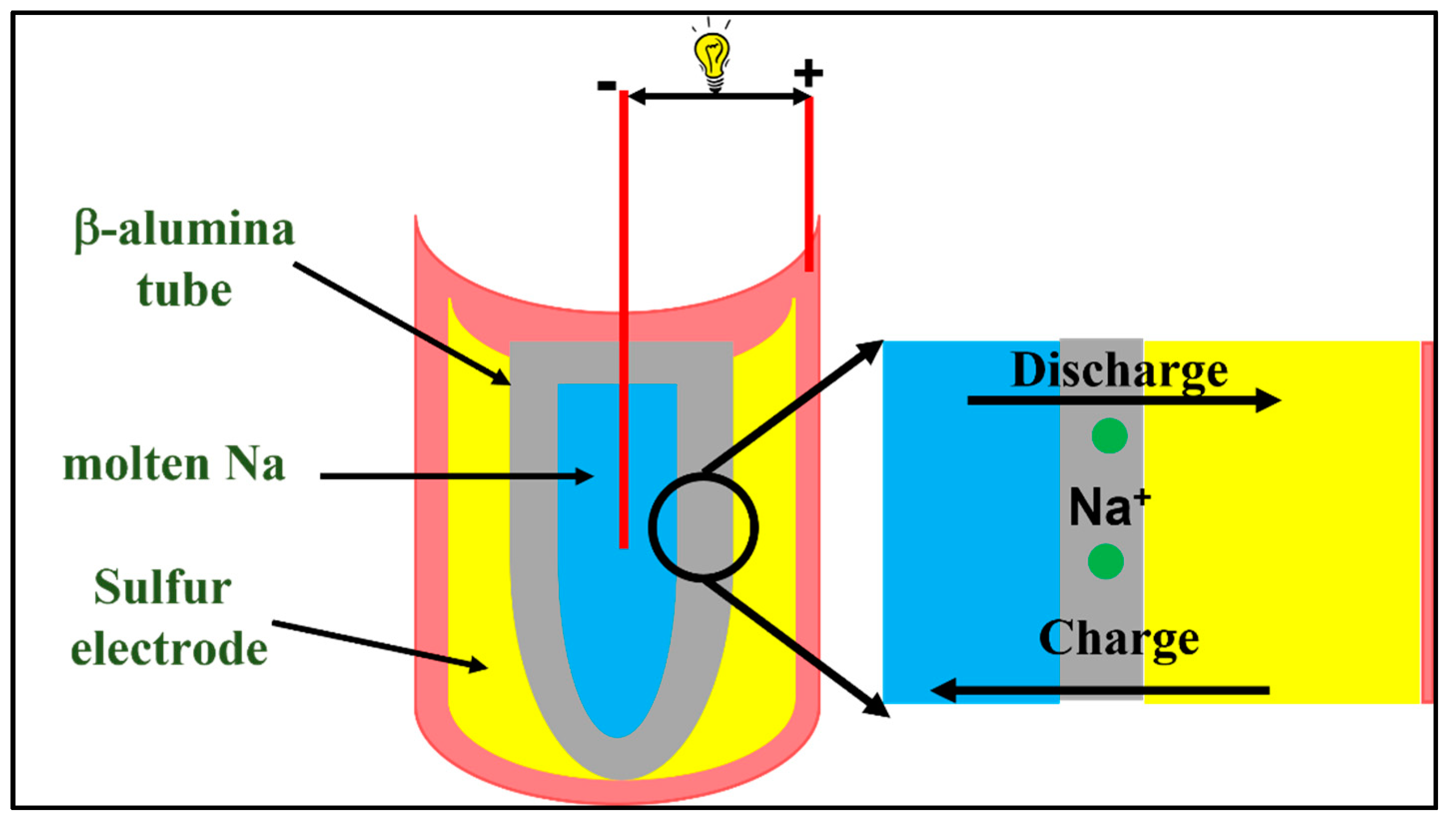
1.2. Sodium Sulfur (Na-S) Battery

In addition to the challenges associated with sulfur cathode, safety and the high cost of lithium metal anodes is another concern in the commercialization of Li-S batteries. To solve this issue, research programs are going to replace lithium anodes with sodium anodes. As sodium shows a redox behavior similar to the lithium anode, research is going to develop a sodium-based sulfur battery by replacing the lithium anode [60,61]. Sodium is much more abundant than lithium, which will result in cheaper sodium–sulfur (Na-S) batteries compared to the Li-S [62]. Owing to these advantages, the early literature is mainly based on high temperature sodium–sulfur (HT Na-S) batteries. The HT Na-S cell has a similar configuration, as shown in Figure 2, where an Na anode and sulfur cathode is used in molten state. Instead of separator, a sodium β-alumina tube is used which acts as both separator and electrolyte. The first industrial application of the HT NaS cell was demonstrated in 2002 for electric power generation. This HT Na-S battery has several advantages such as excellent cycling life, high specific energy density (760 Wh kg−1), high efficiency (~100%), etc. Additionally, the low production cost of the cells makes them excellent choices for large scale energy storage [63,64,65]. However, the very high operation temperature of this system (300–350 °C) increases the maintenance cost and introduces safety problems [66,67,68]. These serious disadvantages associated with HT Na-S batteries paved the way for the exploration of the Na-S conversion chemistry at room temperature [69,70].
Development of RT Na-S battery and its operating principle: Due to the several advantages of the Na-S system for large scale energy storage, research is going to develop the Na-S battery at room temperature. As shown in Figure 3a, a RT Na-S cell comprising a sodium metal anode, composite sulfur cathode and a solution of sodium salt (e.g., NaClO4, NaPF6, NaTFSI) in an organic solvent mixture (e.g., EC/PC, EC/DME, DOL/DME) electrolyte. Similar to the Li-S cell, during the discharge cycle, oxidation of Na+ takes place at the anode and the Na+ ion migrates towards the cathode through the electrolyte. The electron moved towards the cathode through the external circuit, resulting in the generation of electrical current. On the cathode side, sulfur reduced to form various intermediate sodium polysulfides by reacting with the Na+ ion.
The reaction involved in the charge/discharge process of the RT Na-S cell is as follows:
Anode: Na → Na+ + e-;
Cathode: nS + 2Na+ + 2e- ↔ Na2Sn (4 ≤ n ≤ 8).
As shown in Figure 3b, the first discharge cycle is divided into four different regions. The Ι-Region represents a high-voltage plateau region, which shows the solid–liquid transition from element sulfur to higher order sodium polysulfides:
S8 + 2Na+ + 2e- → Na2.
II-Region shows the liquid–liquid reaction from the dissolved Na2S8 to Na2S4:
Na2S8 + 2Na+ + 2e- → Na2S8.
III-Region shows the liquid –solid transition from the dissolved Na2S4 to insoluble Na2S3 or Na2S2:
Na2S4 + 3/2Na+ + 2/3e- → 4/3Na2S3;
Na2S4 + 2Na+ + 2e- → 2Na2S2;
Na2S4 + 6Na+ + 6e- → 4Na2S2.
IV-Region shows the solid-to-solid conversion (i.e., Na2S2 to Na2S):
Na2S2 + 2Na+ + 2e- → 2Na2S.
Out of the four different regions of the Na-S discharge process, the second region is the complex one and it is governed by the equilibria between the different types of intermediate polysulfides. The final discharge products, such as Na2S2 and Na2S, are insulating and make the IV-Region kinetically unfavorable, resulting in high voltage polarization [69,71,72,73].
Figure 3. (a) Schematic representation of the room-temperature sodium–sulfur (RT Na-S battery); (b) typical discharge profile of RT Na/S battery. (Reprinted with permission from [69,73]; Copyright 2014, ChemElectroChem 2014, 1, 1275–1280.)
Batteries 09 00110 g003
Challenges for RT Na-S batteries: The problems associated with the Li-S battery carry over to the RT Na-S battery and become even more aggravated in the latter case. This results in a low active materials utilization, less capacity and poor cycle life of the RT Na-S cell. A detailed discussion on these points is provided below:
Insulating nature of sulfur and sodium polysulfides: Elemental sulfur (S8) and intermediate polysulfides, formed during the discharge (e.g., Na2S2 and Na2S), are insulating in nature. As a result, to improve the conductivity of the cathode, a high fraction of a conductive material is required. This results in the decrease in the loading of active sulfur in the cathode.
Volume change: Due to the larger ionic size of Na+ (ionic radius of Na+ = 0.95) compared to Li+(ionic radius of Li+ = 0.60), the volume expansion in the Na-S system is expected to be higher [74]. The volume expansion in the case of the Na-S system is much higher (260%) compares to the Li-S system (80%). The drastic volume change of cathode weakens the mechanical integrity of the host, thereby reducing the sulfur–host matrix contacts, resulting in a capacity fade.
Dissolution of intermediate polysulfides: The dissolved polysulfides contaminate the electrolyte. The leaching out of the active mass from the cathode, affecting the anode surface with deposits resulting from the disproportionation of polysulfides into insoluble non-conductive sulfides, persists in this case as well.
Formation of sodium dendrites: Due to the non-homogeneous deposition of Na, Na-dendrites may form and grow in an uncontrolled manner, leading to the shorting of the cell [75,76,77,78,79]. Figure 4 shows a schematic representation of challenges in metal (Li/Na)–sulfur batteries.

2. Replacement of Liquid Organic Electrolyte with Solid Electrolytes (SEs)

Currently, there is enormous work going on to control the challenges associated with uses of liquid electrolyte in metal–sulfur batteries. In the literature, many ideas have been proposed to reduce the intermediate polysulfide dissolution such as modification in the cathode, anode, electrolyte and separators [80,81,82]. All these efforts help to decrease the dissolution of polysulfides to some extent. An additional strategy is to confine the liquid electrolyte in a polymer matrix to entrap the intermediate polysulfides [83,84,85]. Although enormous attempts were made to improve the performance of metal–sulfur batteries, the intermediate polysulfide dissolution, anode corrosion, remains a challenge in the conventional metal–sulfur batteries. Replacement of ether-based liquid organic electrolytes by solid electrolytes (SEs) is one of the efficient solutions to these challenges. Solid electrolytes serve as electrochemical barriers between cathode and anode and restrict the polysulfides shuttle. The structure of solid electrolyte is mechanically robust, which also restricts the dendrite growth on the anode side which reduces the risk of short circuiting the cell and improves its safety. Therefore, SEs are potential alternatives to liquid organic electrolytes in metal–sulfur batteries. These SEs should have high electrochemical window, good mechanical properties, excellent RT ionic conductivity, negligible polysulfide dissolution and better thermal stability [86]. Additionally, the SEs provide a uniform and compact structure between anode and cathode, which improves the safety of the cell. The progress in the SEs research requires properties such as high ionic conductivity, good mechanical strength, low interfacial resistance and easy fabrication process [87,88,89,90]. In the past few years, various SEs, such as polymer-based solid electrolyte, inorganic solid electrolytes (viz. oxides-based SEs and sulfides-based SEs), composite solid electrolytes, etc., have been reported in the solid-state metal–sulfur batteries. However, low electrochemical stability window, poor interfaces contact, and low ionic conductivity limit the battery performance. In the past few years, many reviews on the SEs of metal–sulfur batteries have been reported. However, these review articles mostly discuss the challenges and possible solutions of SEs and very few reports have described the desire criteria for SEs. Therefore, before describing the progress in the development of SEs for metal–sulfur batteries, we will first provide a basic introduction to all-solid-state metal–sulfur batteries and the fundamental requirements for an electrolyte to meet the practical applications of all-solid-state metal–sulfur batteries. Later, we will focus on the recent progress in SEs and the understanding of the electrode–electrolyte interfaces of all-solid-state Li/Na-S batteries.

3. All-solid-state Metal–sulfur Batteries

All-solid-state metal (Li, Na)–sulfur batteries consist of three components: (1) Li/Na metal anode; (2) solid electrolyte; (3) Sulfur at the cathode, as shown in Figure 5. The sulfur has much less conductivity (10−30 S cm−1). Therefore, we need to add 15–20% of conducting materials in order to improve the conductivity of the sulfur cathode. Similar to the conventional metal–sulfur battery, metal (Li/Na) is directly used as the anode. This results in high specific capacity and high energy density of the cell. Some of the reported metal alloys (e.g., LiIn, LiSn, etc.) have been reported to reduce the dendrite growth during battery cycling. Replacement of liquid electrolyte into SEs results in the direct conversion of elemental sulfur (S8) to metal sulfids (Li2S, Na2S) during discharge. Formation of intermediate polysulfides does not take place, especially in the case of an inorganic solid electrolyte. The conventional Li-S cell with liquid organic electrolyte shows good interfacial properties; the low interfacial resistance is occurring due to the good wetting of sulfur cathode with liquid electrolyte. However, the interface in the all-solid-state Li-S batteries shows high impedance due to the poor contact between sulfur cathode and solid electrolyte. Additionally, the poor conductivity (ionic + electronic) of sulfur cathode, low utilization of sulfur into the cathode, dendrite growth on the anode and high thickness of solid electrolyte are the challenges faced by this system which restrict the large-scale application of this system. Various efforts have been made to solve such issues by designing the high conducting sulfur cathode. Utilization of solid electrolyte into the cathode is an efficient way to solve such issues. In recent years, people have utilized high-energy ball-milling to make the composite electrode by mixing sulfur cathode with solid electrolyte and conducting carbon. However, in the present review article, we only focus on the solid electrolyte and do not report the issue that S affects the electrochemistry of the cell. Design of sulfur cathode, loading of sulfur and the effect of sulfur in the electrochemistry are beyond the scope of this review article.

4. Fundamental Requirements of Solid Electrolyte to Meet the Practical Applications

The electrolyte is the most important component of the electrochemical cell. It allows ion conduction between both electrodes. As discussed earlier, most research focused on metal–sulfur batteries has utilized ether-based liquid organic electrolyte. The use of liquid organic electrolytes is beneficial due to their high ionic conductivity, ease of processing and good wetting capabilities of the electrode materials. Nevertheless, the usage of organic solvents is imposing some critical technical and practical limitations. These limitations are related to safety issues (due to electrolyte flammability), longevity issues (due to electrolyte degradation and volatility) and the limited energy density of the battery (due to the solvent’s limited electrochemical stability) [91,92,93,94,95,96,97]. In recent years, there has been increased interest in developing solid electrolytes (SEs) for all-solid-state Li/Na-sulfur batteries. All-solid-state Li/Na-sulfur batteries could potentially increase the current volumetric/specific energy density. Furthermore, eliminating the volatile organic electrolyte in all-solid-state Li/Na-sulfur will significantly improve the safety of the battery and extend the operating temperature of the cell. Hence, replacement of liquid electrolyte with solid electrolyte is required for high performance and a safe battery. Ideal SEs should have the following properties: high ionic conductivity, negligible electronic conductance, high Li+/Na+ transference number, wide electrochemical stability window, good thermal stability, good mechanical strength, less interfacial resistance and low cost and facile synthesis. In the following section we will discuss some of the fundamental properties required by a solid electrolyte to meet the practical applications.
Ionic conductivity: High ionic conductivity is one of the most necessary parameters of a SEs to meet the practical application of all solid–state metal–sulfur batteries. High ionic conductivity of SEs accelerates the ion transport between the electrode resulting in better cell performance. The ionic conductivity of the SEs is related to the crystal structure of the materials. The ionic conductivity is dependent on defects in the crystal structures. There are many types of defects, such as point defects, plan defects, line defects and volume defects. Amongst all the defects, the point defects play an important role in the ion-conduction of the materials. For any SEs materials, point defects govern the ionic conductivity of the materials and the crystal structure of SEs, which includes the spatial arrangement of the motionless framework and mobile ions. The interaction between Li+/Na+ ions and the motionless framework has a significant effect on the Li-ion migration. Previous reports in the field of SEs have shown that the mobile ion diffusion around the grain boundaries is the rate determining step. The high fraction of grain boundaries provides an efficient ion-transport path which results in a high conductivity value for SEs. Polymer solid electrolytes show less ionic conductivity compared to that of inorganic solid electrolytes. For example, oxide-based solid electrolytes such as Li3.3La0.56TiO3 (LLTO), Li7La3Zr2O12 (LLZO), LiTi2(PO4)3 (NASICON) and Li14Zn(GeO4)4 (LISICON) show ionic conductivity 10−4 S cm−1; however, polymer electrolytes show an ionic conductivity that is two order lower (≈10−6 Scm−1) than that of inorganic solid electrolytes [98,99,100,101]. Very few of the inorganic SEs show high ionic conductivity ((≈10−3 Scm−1). NASICON-type Li1.3AL0.3Ti1.7(PO4)3 and Li3PS4 are the example of SEs which show excellent ionic conductivity (10−3 S cm−1) at room temperature [102,103,104,105,106].
High cation transference number: The ratio of the electric current driven by cation (Li+, Na+, etc.) to the total electric current is defined as the transference number. The higher transference number means higher ionic conductivity of the solid electrolyte. A large transference number results in less charge/discharge polarization and thus improves the electrochemical performance of the solid electrolyte. It is extremely advantageous that the transference number of the cation (Li+, Na+, etc.) should be close to 1 in an electrolyte system. However, most of the reported electrolytes show a transference number of less than 1. An ideal solid electrolyte should have a high cation transference number. In general, a solid electrolyte with a high transference number shows rapid charge/discharge characteristics [107,108].
Interfacial compatibility: All the components of all-solid-state metal–sulfur batteries are comprised of solid materials. An unstable, highly resistive interface formation takes place at the SEs cathode interface. Various research is being undertaken to improve the compatibility of the solid electrolyte–sulfur/cathode interface. Inorganic solid electrolyte interfaces show more prominent incompatibility with the sulfur cathode compared to that of the polymer-based solid electrolyte. High polarization and slow kinetics occur during the galvanostatic charge/discharge due to the highly resistive interface. Various strategies have been used in recent years to solve the interface problem in all-solid-state metal–sulfur batteries such as introducing the additional layers to the cathode/anode to increase the contact area via various deposition technology [109]. We need to choose a solid electrolyte which shows compatibility with the sulfur-based cathode in order to obtain stable all-solid-state metal–sulfur batteries.
Electrochemical stability: The ability of an electrolyte to maintain stable physical and chemical properties during charge/discharge in the given voltage range is known as electrochemical stability. We need to choose the SEs in such a way that they maintain electrochemical stability during the cycling of the cell in the given voltage range. Metal–sulfur batteries used highly reactive metal (Li/Na) as an anode. These metal anodes can easily react with electrolytes and result in electrochemical uncertainty in the system. Solid polymer electrolytes show stable electrochemical stability against the sulfur cathode compared to inorganic sulfide-based solid electrolytes. Inorganic sulfides-based solid electrolytes show low interfacial resistance and high ionic conductivity which makes them a potential candidate among various SEs. Despite of high conductivity and good interfacial property, sulfides-based electrolytes are sensitive to water and very reactive towards lithium metal, which substantially limits the application of these electrolyte [110,111,112]. Advantages and disadvantages of the different electrolyte systems discussed in the present review are summarized in Table 1.

5. Recent Progress in Solid Electrolyte for Li-S Batteries

The most important component of the rechargeable batteries is the electrolyte. It transports the ion between both electrodes. Most of the literature on metal–sulfur batteries uses liquid organic electrolyte (Such as: LiTFSI in DOL/DME). Due to the use of the liquid electrolyte, metal–sulfur battery technology faces some critical challenges which restricts the commercialization of metal–sulfur batteries. The energy storage process in the Li-S cell is not a single-step process; it involves many steps of the reversible conversion of elemental sulfur (S8) to metal–sulfide. During the discharge process various intermediate polysulfides forms at the cathode. Some of the higher order polysulfides (such as Li2S8, Li2S6) are soluble into the ether-based liquid electrolyte. Once the higher order polysulfides dissolved into the electrolyte, they migrate between both the electrode and resulting in low utilization of active sulfur, poor cycle life and low capacity. Additionally, the high flammability, high volatility, and low boiling point of the solvent used in electrolyte (such as: DOL, DME, TEGDME etc.) increases the safety issues. Therefore, there is a strong need to explore the new electrolyte through which we can get rid of the challenges associated with liquid organic electrolyte. Replacement of liquid organic electrolyte by solid electrolyte (SEs) is one of the proposed solutions of these challenges. In the recent research, solid electrolytes (SEs) are broadly categorized into three types depending on the physical and electrochemical properties: inorganic solid electrolyte, polymer electrolyte and composite solid electrolytes. Currently, most of the solid electrolytes face challenges such as low ionic conductivity, poor solid electrolyte interfaces, low electrochemical stability window and high resistance at the interface.
Different electrolyte systems have different ion-conduction mechanisms. Ionic conductivity in the liquid electrolyte is taking place by movement of solvated ions in the solvent. The ionic conductivity can be improved by ion concentration and ion dissociation in the solvents. The ion dissociation is governed by the dielectric constant of the electrolyte. The salt with a high value of dielectric constant will have high dissociation. The viscosity of the solvents also has the effect on ion conduction of the electrolyte. The highly viscous solvent results in low ionic conductivity. In contrast, the ion conduction in the solid electrolyte is related to the crystal structure of the solid electrolyte materials. The ion conduction is dependent on the defect of the crystal structures. Defects include point defects, plan defects, line defects and volume defects. Amongst all the defects, the point defects play an important role in the ion-conduction of the materials. For any SEs materials, point defects govern the ionic conductivity of the materials and the crystal structure of SEs, which includes spatial arrangement of the motionless framework and mobile ions. The interaction between Li+/Na+ ions and the motionless framework has a significant effect on Li+/Na+-ion migration. In the following section of the review article, we will discuss the recent progress of SEs in all-solid-state Li-S batteries. The pros and cons of all the electrolyte system will be discussed and future perspective will be described systematically.

5.1. Inorganic Solid Electrolyte

Inorganic solid electrolytes show improved electrochemical stability window, high ionic conductivity, better mechanical strength, and thermal stability. Additionally, inorganic solid electrolytes restrict polysulfide dissolution and inhibit the polysulfide shuttle between anode and cathode. The wide electrochemical window of the inorganic solid electrolyte matches well with the high-voltage cathode which results in metal–sulfur batteries with improved specific energy density. The high mechanical strength of inorganic solid electrolyte forms a robust structure between anode and sulfur cathode which restrict the short circuit caused by dendrite growth. In the current research, the inorganic solid electrolyte consists of two widely studied group of materials: oxide inorganic solid electrolyte and sulfides inorganic solid electrolyte. Glasses and glass ceramic ionic conductors fall under sulfides-based SEs. On the other hand, LISICON, NASICON, garnet-based and perovskite-based SEs collectively fall under oxide-based solid electrolytes. Despite of high ionic conductivity and wide electrochemical window, inorganic solid electrolytes suffer with high contact resistance. The high contact resistance and poor interface arises due to the stiff contact between SEs and sulfur cathode. We will discuss the current progress in the field of inorganic solid electrolyte (viz. oxide-based and sulfides-based solid electrolyte) in the following section.
Oxide-based inorganic solid electrolyte: The oxide-based solid electrolyte shows high ionic conductivity, wide electrochemical stability window and good mechanical strength compared to the polymer-based solid electrolyte. These solid electrolytes are broadly divided into NASICON-type, perovskite-type, garnet-type and LISICON type electrolytes. The commercial utilization of such electrolytes is hindered by their poor interface, stiff nature and high interfacial resistance. The perovskite-type Li3xLA2/3-xTiO3 (LLTO) electrolytes with high ionic conductivity (≈10−4 Scm−1) have been wildly used in Zn-ion batteries [113,114,115]. LLZO is another class of oxide solid electrolyte which also shows excellent ionic conductivity (≈10−3–10−4 Scm−1) and is wildly used in the literature. The ionic conductivity of Li7La3Zr2O12 (LLZO) electrolytes is reported as 7.74 × 10⁻⁴ S cm−1 at room temperature [116]. It was also reported that the high valence doping of Ta in LLZO will improve the ionic conductivity of the solid electrolyte to 10−3 Scm−1. The composition of the Ta doped LLZO solid electrolyte is Li6.4La3Zr1.4Ta0.6O12 (LLZTO), which shows good stability with the Li metal anode [117]. High interfacial resistance is the major issue which hindered the practical application of LLZO-based solid electrolytes. Many research strategies have been proposed to solve this issue. Utilizing a conducting layer between the electrode and LLZO electrolyte is a well-known method to solve such issue. Yijun et al. have developed a composite anode to improve the ionic and electronic conductivity. They have utilized Li3N as an ionic conductivity phase and Fe-Fe3C as an electronic conductivity phase. A facile route was employed to obtain the composite anode by reacting Prussian blue (PB) and molten Li. This composite anode shows interfacial properties with the Li6.4La3Zr1.4Ta0.6O12 (LLZO) solid electrolyte [118]. Figure 6 shows the material characterization and ionic/electronic pathway for the Li3N/Fe-Fe3C-based composite anode. The introduction of an aluminum nitride layer is also proposed to improve the interfacial contact between the lithium anode and the LLZO cathode [119]. Coating the surface of LLZO with L-Nafion also improved the interface between the anode and the LLZO solid electrolytes. This strategy reduced the polysulfides shuttle and improved the cycling performance of all-solid-state Li-sulfur batteries [102].
Even though LLTO solid electrolytes show wide electrochemical stability window and good mechanical strength, their performance is limited by the poor interfacial contact. Here, also, it is important to improve the interfacial properties and increase the ion conductivity. SnS2 coating is conducted on garnet-based solid electrolyte (LLTO) to reduce the interfacial resistance of all-solid-state lithium–sulfur batteries. SnS2 coating has improved the battery performance of all-solid-state lithium sulfur batteries [120]. A composite bilayer framework of LLTO/PEO composite electrolyte and 3D CNF/S cathode is proposed, which shows improved ion-transport and enhances the interfacial stability of the electrolyte [121]. In recently published work, Xin et al. have cladded an electron deficient Li2B4O7 nanoparticle with carbon nanofibers (LBN-CNF) and used as an interlayer for all solid-state Li-S battery [122]. Xingwen et al. have used a NASICON-type (Li1+xYxZr2-x(PO4)3 oxide-based solid electrolyte for all-solid-state Li-S battery. They observed a significant improvement in the cell performance and a reduction in polysulfide dissolution [123]. A schematic of the all-solid-state Li-S cell using NASICON-type (Li1+xYxZr2-x(PO4)3 solid electrolyte is shown in Figure 7a. The NASICON-type (Li1+xYxZr2-x(PO4)3 membrane is acting as solid electrolyte (Li+-ion conductor) as well as separator (electronic insulator). A piece of thin polypropylene film was introduced between the lithium anode and the solid electrolyte to insure the superficial ionic interface. Figure 7b shows the voltage versus time plot of the all-solid-state Li-S cell. The voltage profile of the cell shows two plateaus which is similar to the conventional Li-S cell with the liquid organic electrolyte. Figure 7c shows the cyclic voltammetry of the all-solid-state Li-S cell using the NASICON-type (Li1+xYxZr2-x(PO4)3 solid electrolyte. Cyclic voltammogram shows the anodic peak with more positive potential and the cathodic peak with more negative potential for the initial 1.5 cycles. After the second cycle, there is negligible difference between potential position. Figure 7d shows the galvanostatic charge/discharge of the all-solid-state Li-S cell at different current rates. It is observed from the galvanostatic charge/discharge curve that there is a significant decrease in the specific capacity of the cell with increasing current rates. Figure 7e,f shows the discharge capacity and coulombic efficiency of the all-solid-state Li-S cell as a function the of number of cycles.
Sulfides-based inorganic solid electrolyte: The sulfides-based inorganic solid electrolyte shows superior ion conduction and low interfacial resistance compared to the oxide-based solid electrolyte. Additionally, sulfides-based inorganic solid electrolytes show better compatibility with sulfur cathodes, making them a potential candidate for all-solid-state lithium–sulfur battery applications. Despite these positive characteristic, sulfides-based solid electrolytes usually suffer with low electrochemical stability window which restricts their use against high voltage cathodes. The superior performance of sulfides-based solid electrolytes compared to oxides-based electrolytes is also due to the low electronegativity of the elemental sulfur compared to that of the oxygen. The weak bond between Li+-S is responsible for high ion conduction in the sulfides-based solid electrolyte. As we discussed previously, using the sulfides-based solid electrolyte has several benefits, as well as some challenges (such as high interfacial resistance and stress/strain). These challenges need to be overcome in order to facilitate their commercialization. In this direction, Yao et al. have reported an all-solid-state lithium–sulfur cell comprising rGO@S-Li10GeP2S12-acetylene black composite as the cathode. A conformal coating of sulfur (≈2 nm) onto reduced graphene oxide (rGO) was undertaken to reduce the interface resistance. The all-solid-state lithium–sulfur cell shows superior performance, similar to that of the cell with liquid electrolyte [124]. Wang et al. have synthesized a highly conducting (≈3.15 × 10⁻³ Scm−1 at room temperature) argyrodite-based Li6PS5Cl solid state electrolyte by solid-state synthesis protocol. The all-solid-state lithium–sulfur cell was assembled by using an Li6PS5Cl solid-state electrolyte, a nano-sulfur/multiwall carbon nanotube composite as the cathode and Li-In alloy as the anode. The cell shows excellent discharge capacity of 1850 mAhg−1 at room temperature at current rate C/10. Additionally, the coulombic efficiency of the cell remains 100% throughout the galvanostatic cycling. This work confirms that argyrodite-based sulfide solid electrolytes are the potential candidates for all-solid-state lithium–sulfur battery [125]. Umeshbabu et al. have used 1M LiTFSI/PYR13TFSI ionic liquid as a surface modifier for Li10GeP2S12 (LGPS) solid electrolyte. This strategy improved the compatibility of Li10GeP2S12 (LGPS) solid electrolyte and lithium metal anode. They have also studied the effect of carbon additives inside the sulfur composite cathode of quasi-solid-state lithium–sulfur cells. They have shown the remarkable stabilization of the LGPS solid electrolyte interface with lithium metal anode. The schematic representation of the quasi-solid-state lithium–sulfur cell, comprising AB cathode, LGPS solid electrolyte and lithium metal as the anode is shown in Figure 8A. Figure 8B shows the first galvanostatic charge/discharge curves for different S@C composite cathodes at current rate 83.5 mAg−1. The first discharge capacity of the Li-S cell with S@KBC, S@PBX51C and S@MWCNT is found to be 1068 mAhg−1, 783 mAhg−1 and 667 mAhg−1, respectively. Figure 8C shows the specific discharge capacity versus number of cycles of Li-S cell with various cathodes. Figure 8D shows the electrochemical impedance spectroscopy of the Li-S cell with various cathodes [126].
Other challenges associated with Li10GeP2S12 (LGPS) solid electrolytes, such as instability against lithium anodes and dendrite growth, were addressed by an Mg(TFSI)2-LiTFSI-DME gradient interlayer between the LGPS solid electrolyte and lithium anode [127]. Yang et al. have proposed yttrium doping into the argyrodite-based Li6PS5Cl (LPSCl) solid electrolyte to improve the conductivity as well as the interfacial stability. After yttrium doping, the LPSCl electrolyte shows high ionic conductivity (3.3 × 10⁻³ S cm−1). This conductivity value is found to be two times higher than that of the pristine LPSCl (1.5 × 10⁻³ Scm−1) [128]. Sulfides-based solid electrolytes are the widely used solid electrolytes due to their high ionic conductivity and good mechanical strength. The dendrite growth and instability against lithium are the further challenges which need to be address in their practical application. These challenges can be rectified by using a protective layer between the solid electrolyte and anode.

5.2. Polymer Electrolyte

Polymer electrolytes have superior flexibility to inorganic solid electrolytes, which makes them more suitable candidates for the sulfur cathode. The excellent flexibility of polymer electrolytes can adjust the volume changes which occur in the sulfur cathode during battery cycling. Apart from their flexible nature, polymer electrolytes also show better interface contact compared to inorganic solid electrolytes. However, polymer electrolytes suffer from weak ion conduction, poor mechanical strength and intermediate polysulfide dissolution. Various polymer-based solid electrolytes have been used recently in solid state metal–sulfur batteries research. Some of the widely used polymer matrix are polyacrylonitrile (PAN)-based polymer electrolytes, polyvinylidene fluoride (PVDF)-based polymer electrolytes, polyethylene oxide (PEO)-based polymer electrolytes and polymethyl methacrylate (PMMA) polymer electrolytes, etc. In the following section we will discuss about the recent progress in polymer-based solid electrolytes.
Gel Polymer Electrolytes (GPEs): GPEs contains two major components: (a) liquid solutions of lithium salt (e.g., LiTFSI and LiPF6); (b) a solid polymer matrix (e.g., PAN, PEO and PMMA etc.). The liquid solution enhances the ionic conductivity/electrochemical properties of the electrolyte and polymer matrix to ensure the mechanical strength [129]. Han et al. proposed a GPE for Li-S battery by surface modification of the PVDF-based GPEs. They have utilized polydopamine (PDA) to stabilize the Li anode. This GPE reduced polysulfide dissolution by entrapping the higher order polysulfides at the functional group of PDA. Additionally, GPEs stabilize the lithium anode and form a stable interface at lithium anode [130]. Recently, Sheng et al. have reported a PEO–PAN-based crosslinked membrane GPE with a PAN fiber as a filter. This GPE shows excellent ionic conductivity, good mechanical strength and high Li-ion transference number. The Li-S cell with PEO–PAN-based GPEs displays high specific capacity, good rate capability and cycling stability. Spectroscopic analysis and theoretical simulations confirm the reduction of polysulfides shuttle by N-containing groups. Due to the strong bonding ability and high flexibility, this GPE shows good interfacial contact with cathode and anode which results in stable Li-S battery performance [131]. Various efforts have been made to reduce the intermediate polysulfide dissolution and improve the Li-S battery performance by using GPEs. The GPEs synthesized by the standard method show low ionic conductivity, which results in poor battery performance, low energy density and high cost of production. Liu et al. have proposed an acrylate-based hierarchical electrolyte (AHE) with a facile and cost-effective synthesis route. This GPE is synthesized by the in-situ gelation of a pentaerythritol tetra acrylate (PETEA), using a polymethyl methacrylate (PMMA)-based electrospun network. This GPE shows high ionic conductivity (1.02 × 10⁻³ Scm−1) and good mechanical strength. The Li-S cell using this GPE shows high-rate capability 645 mAhg−1 at 3C, excellent capacity retention and good cycling stability [132]. Figure 9 shows the synthesis and structural characterization of the PMMA-based electrospun fiber network. Figure 9a shows the SEM image of the PMMA-based electrospun fiber network GPE.
Solid Polymer Electrolytes: Solid polymer electrolytes (SPEs) show good mechanical strength, wide electrochemical stability window, non-flammability and ease of preparation. SPEs are prepared by using a lithium salt and polar polymer matrix and eliminating the liquid components. SPEs show less ionic conductivity compared to that of the GPEs at room temperature. SPEs are considered good candidates for application in high energy lithium–sulfur batteries due to their high safety and excellent flexibility towards the sulfur cathode. To improve the conductivity, Lin et al. synthesized a novel SPE film using natural nano-clay. This SPEs shows an excellent ionic conductivity of (1.11 × 10⁻⁴ S cm−1), high lithium-ion transference number of 0.40 and improved lithium-ion transport. The Li-S battery using natural nano-clay-based SPEs can work over a broad range of temperatures (20 °C–100 °C) [133]. The ionic conductivity of SPEs at room temperature is found to be (10−8–10−4 Scm−1). However, the HNT-based SPEs show an ionic conductivity of 2.14 × 10⁻³ Scm−1 at 100 °C. It is observed that the Lewis acid–base interaction between HNT, LiTFSI and PEO provide the optimum path for lithium-ion migration; this could be the reason for improved ionic conductivity. Liang et al. have proposed a novel route for synthesizing an SPE which maintains noth the mechanical strength and ionic conductivity. They have utilized a hydrolyzation method to synthesis a zirconium dioxide skeleton with vertical channels (ZrO2@ILs). After that, the (ZrO2@ILs) is combined with PEO matrix to form SPEs. ZrO2@ILs-based SPEs show high conductivity and mechanical strength. The ILs channels provide an improved lithium-ion transportation and ZrO2 increase the SPEs modulus and rigidness. The Li-S cell with ZrO2@ILs-based SPEs shows excellent electrochemical performance, rate capability and cycling stability [134].

5.3. Composite Electrolytes

Although ISEs are the best solid electrolyte in terms of ionic conductivity, mechanical strength and electrochemical stability window, they suffer due to their poor interfacial property and high interfacial resistance. In encountering such issues, composite electrolytes have drawn increasing attention. Composite electrolytes show low interfacial resistance and high lithium-ion conductivity. Generally, the inclusion of inorganic fillers into organic polymer electrolytes will employ the synergistic effect which increases the ionic conductivity of composite electrolytes. Xie et al. have proposed a novel PEO–PAN–LLZO composite GPEs by using liquid-phase synthesis. On top of the dispersion of PAN, PEO and LLZO, a porous composite membrane is formed with good mechanical and interfacial property. This membrane can effectively absorb the electrolyte and prevent the polysulfides shuttle to protect the lithium metal anode. The PEO–PAN–LLZO composite electrolyte shows good interfacial compatibility with the lithium anode and provides uniform lithium stripping/platting. The additional carbon coating on the membrane efficiently hampered the intermediate polysulfide migration and improved the kinetics of the charge/discharge. The Li-S cell with the composite electrolyte shows a remarkable battery performance. The specific capacities of the Li-S cell at current rate C/10 and 1C is found to be 1459 and 942 mAhg−1, respectively. Additionally, the cell shows an extraordinary cycling stability of 500 cycle with a capacity retention of 82% [135].

6. Recent Progress in Solid Electrolyte for Na-S Batteries

All-solid-state Na-S batteries are more desired candidates compared to all-solid-state Li-S batteries due to the high earth abundance of sodium and their similar electrochemical properties to lithium [136,137,138]. Lithium is partially available and non-homogenously distributed around the world. However, the abundance of sodium is very high; it is the 4th most earth abondance element [139]. The availability of sodium in the earth crust is reported to be very high (28400 mgKg−1) compared to that of lithium (20 mg Kg−1) [140,141]. After lithium, sodium is the 2nd smallest element in the periodic table and the electrochemical property of sodium is similar to lithium. All these properties makes sodium the best potential candidate for large scale energy storage. On top of it, the manufacturing cost of all-solid-state Na-S batteries is far below that of the all solid-state Li-S batteries. Consequently, recent research is focusing on developing all-solid-state Na-S batteries at room temperature. Similar to the Li-S system, the liquid electrolytes in the Na-S system result in the dissolution of intermediate polysulfides and the diffusion of higher order polysulfides between the cathode and anode i.e., the “shuttle effect”. The polysulfides corrode the sodium anode and limit the capacity to far below the theoretically calculated value. Additionally, the high flammability, high volatility, and low boiling point of the solvent used in the electrolyte (such as: DOL, DME, TEGDME etc.) increases the safety issues. Furthermore, the liquid organic electrolyte shows narrow electrochemical stability window which makes it incompatible with a high-voltage cathode. The ether-based liquid organic electrolyte creates unstable SEI as the electrolyte becomes oxidize at the anode surface, which results in an unstable Na-S battery with low specific capacity and low coulombic efficiency. It has been reported that the replacement of the liquid organic electrolyte with a solvent-free solid-state electrolyte results in stable Na-S battery performance. The solid electrolyte shows wide electrochemical stability window, good mechanical strength, negligible polysulfide dissolution and shuttle from cathode to sodium anode. Additionally, solid electrolyte improves the safety of the cell and inhibits the dendrite growth on the sodium anode. As solid electrolyte is free from the “polysulfides shuttle”, the solid-state Na-S battery results in better capacity retention and improved coulombic efficiency. However, there are several common challenges faced by the performance of the solid electrolyte, such as poor contact, high interfacial resistance and low ionic conductivity at room temperature. Based on the preparation method, and material properties of the solid electrolyte for the RT Na-S battery are broadly divided into three parts: inorganic solid electrolyte, polymer electrolyte and composite solid electrolytes. Development of all-solid-state Na-S batteries at room temperature using solid electrolytes provides a promising candidate for large-scale energy storage. This cell configuration offers high energy density and excellent safety. Among the various solid electrolytes, sulfides-based solid electrolytes are the more promising for all-solid-state Na-S batteries. Tanibata et al. have reported a high capacity, low materials cost and improved safety in the all solid-state Na-S cell using Na3PS4 glass–ceramic solid electrolyte. Mechanical milling was used to prepared sulfur composite cathodes by mixing acetylene black and sulfur. The final discharge product of the all-solid-state Na-S cell was reported as Na2S and the cell showed a specific capacity of 1100 mAhg−1 at room temperature. The sulfur utilization is found to be very high compared to that of the commercially available high temperature Na-S batteries [142]. The current trend is to fabricate the all-solid-state Na-S battery by a simple cold-pressing method. This process is simple and easy, but it results in high residential stress. During the discharge, elemental sulfur S8 converts to Na2S which results in high-volume expansion in the cathode. The large volume expansion stresses the mechanical integrity of the cell, resulting in poor interfacial contact between the solid electrolyte and the cathode. Fan et al. proposed a casting–annealing technology to prepare the cathode for the all-solid-state Na-S battery. They have synthesized a Na2S-Na3PS4-CMK-3 nanocomposites via melt casting techniques followed by stress release annealing processes. In this way, they achieved the reduction in the interfacial resistance [143].
Figure 10 shows a schematic representation of the synthesis of the Na2S-Na3PS4-CMK-3 nanocomposites cathode. All the precursors (Na2S, P2S5 and CMK-3) are physically mixed well using mortar and pestle inside the glove box. The mixture then underwent for annealing at 270 °C. At high temperatures, Na2S and P2S5 melted and mixed to form a homogeneous liquid. The electronic and ionic conductivity of the Na2S-Na3PS4-CMK-3 nanocomposites cathode can be tuned by changing the ratio of Na2S-P2S5 and CMK-3. Recently, Ge and coworkers proposed a PEO–NaTFSI/Na3Zr2Si2PO12 composite electrolyte for all-solid-state Na-S batteries. The PEO–NaTFSI/Na3Zr2Si2PO12 composite electrolyte shows the highest ionic conductivity (3.14 × 10⁻⁴ Scm−1), an Na-ion transference number of 0.66, an EO/Na+-ion ratio of 20 and the amount of Na3Zr2Si2PO12 is 30% by weight. The all-solid-state Na-S cell was assembled using a sulfur cathode and Na metal as the anode. The cell shows excellent electrochemical performance, rate capability and capacity retention. The discharge capacity of 1110 mAhg−1 was obtained at high current rate C/5 and 60 °C. The cell shows stable cycling up to 60 cycles with a capacity of about 666.8 mAhg−1 and a columbic efficiency 100% [144].
Different compositions of PEO–NaTFSI and Na3Zr2Si2PO12 are prepared by varying the weight ratio of Na3Zr2Si2PO12. Figure 11a shows the conductivity of PEO–NaTFSI at various EO:Na+ ratios. The ionic conductivity increases with the increasing of the EO:Na+ ratio up to 20, and obtained the maximum conductivity. This could be due to the increasing concentration of charge carriers. The effect of Na3Zr2Si2PO12 on the conductivity of the electrolyte was also studied by varying the weight ratio of Na3Zr2Si2PO12, as shown in Figure 11b. The ability of the solid electrolyte to transport the Na+ ion is carried out by transference number investigations. Figure 11c shows the AC impedance and chronoamperometry of Na|| PEO–NaTFSI ||Na cell. Figure 11d shows the polarization cure of Na|| PEO–NaTFSI ||Na cell and equivalent circuit to fit the impedance data. Most of the work related to all-solid-state Na-S batteries suffers with poor cell performance. The high solid-electrolyte/sulfur cathode interfacial resistance is the major drawback of this system. Jie Yue et al. have reported that the Na3PS4-Na2S-C composite cathode solves the interfacial challenge for all-solid-state Na-S batteries [145]. The addition of carbon conducted into the composite cathode improved the interface contact. Utilization of Na2S nanoparticles into the composite cathode improved the cell performance of the all-solid-state Na-S cell. The composite cathode was prepared by mixing Na2S, Na3PS4 and conducting carbon homogeneously, which result in increasing conductivity in the system and the reduction of interfacial resistance. The all-solid-state Na-S cell shows the first discharge capacity of 869.2 mAhg−1. A comparison of the cell performance was carried out by using two different size Na2S particles (i.e., nano sized NPS-micro-Na2S-C and microsized NPS-nano-Na2S-C). Figure 12a shows the cell performance of the all-solid-state Na-S cell with the NPS-micro-Na2S-C composite cathode at various current rates. The cell capacity is found to decrease with the increasing current rate. Figure 12b shows the cell performance of the Na-S cell with the NPS-nano-Na2S-C composite cathode. Figure 12c shows the rate capability of the cell with two different composite cathodes at 60 °C. Figure 12d shows the electrochemical impedance spectroscopy (EIS) of the cell with two different composite cathodes, which shows that the interfacial resistance of the cell with the NPS-nano-Na2S-C composite is much lower than the cell with the NPS-micro-Na2S-C composite cathode.
More recently, Jhang et.al. have utilized sodium alloy anode (Na-Sb and Na-Sn) to eliminate the dendrite formation issue in all-solid-state Na-S batteries [146]. Among the two different alloy anodes, Na3Sb shows a stable alloying/dealloying process at current density 0.04 mAcm−2. A full cell configuration of the all-solid-state Na-S cell was demonstrated by using a sulfur–carbon composite cathode. The sulfur cathode was prepared by using vapor deposition techniques. The cell with the Na-alloy anode and sulfur–carbon composite cathode showed excellent capacity (first discharge capacity ≈ 1377 mAhg-1), and the cell is stable up to 180 cycles, with a capacity retention of 70%.

7. Summary and Conclusions

The global energy demand is continuously increasing to fulfil the energy requirements of portable devices as well as large scale applications (such as electric vehicle and smart grid). All-solid-state metal (Li, Na)–sulfur batteries have become a hot research topic in the field of energy storage due to their high energy density and low cost. To achieve high performance all-solid-state metal–sulfur batteries, a solid electrolyte is the key component; it mitigates the intermediate polysulfides shuttle and dendrite growth and improves the safety of the cell. In this article, we have systematically reviewed the recent progress of solid electrolytes for metal (Li, Na)–sulfur battery applications. This article started with a basic introduction to metal–sulfur batteries (Li-S and Na-S), their working principle and their fundamental challenges. The key challenge of metal–sulfur batteries is the uses of liquid organic electrolyte. We have described the advantage of replacing the liquid organic electrolyte with a solid electrolyte. The fundamental requirements of the solid electrolyte are also discussed. Finally, the recent research progress in the field of solid electrolytes for all-solid-state Li-S and Na-S batteries is reviewed.
As discussed in Section 5, despite the high ionic conductivity and wide electrochemical window of LISICON and NASICON, garnet-based solid electrolytes suffer from high contact resistance. To further enhance the performance of the all-solid-state Li/Na-S batteries, efforts can be made to improve the interfacial challenges of the solid electrolyte–electrode interface. A better understanding of the polysulfides’ chemistry is also required for stable all-solid-state Li/Na-S batteries. We have reviewed the important parameters required for an efficient solid electrolyte to improve battery performance. This review article will help the researcher gain a basic understanding of metal–sulfur batteries, the fundamental challenges associated with metal–sulfur batteries and the solution to those challenges—replacing the liquid electrolyte with solid electrolyte. We strongly believe that this review article will help in the designing of improved, safe and cost-effective solid electrolytes with high conductivity, leading to superior metal–sulfur battery. Future research work can take the following directions.
Designing of new solid electrolyte materials: There is a need to design new solid electrolyte materials with high cation transference numbers, high ionic conductivity, wide electrochemical window, good interfacial properties and good mechanical strength.
Development of in situ/operando techniques to study the interface: Efforts should be made to study the solid electrolyte interface and the mechanism of charge/discharge of all-solid-state Li/Na-S batteries. These types of study can be conducted by utilizing in situ/operando spectrochemical techniques (such in situ/operando Raman), X-ray absorption spectroscopy, transmission electron microscopy, etc. This type of detailed study can help us to understand the interface and assist in the development of new electrolyte materials which show better compatibility with lithium–sodium anodes and high-capacity cathodes.

Author Contributions

Conceptualization: D.Z. and R.K.B. Bibliography screening: R.K.B. Figures: R.K.B. Draft: R.K.B. Proofreading and revision: D.Z. All authors have read and agreed to the published version of the manuscript.

Funding

This work is financially supported by BIRD consortium (US–Israel Energy Centre: Energy storage EC-13).

Institutional Review Board Statement

Not applicable.

Informed Consent Statement

Not applicable.

Data Availability Statement

Not applicable.

Acknowledgments

D.Z. and R.K.B. acknowledge BIRD project: US–Israel Energy Centre (Energy Storage EC-13) for funding.

Conflicts of Interest

The authors declare no conflict of interest.

References

  1. Dunn, B.; Kamath, H.; Tarascon, J. For the Grid: A Battery of Choices. Science 2011, 334, 928. [Google Scholar] [CrossRef]
  2. Armand, M.; Tarascon, J. Building Better Batteries. Nature 2008, 451, 652–657. [Google Scholar] [CrossRef] [PubMed]
  3. Kalyanasundaram, K.; Grätzel, M. Themed Issue: Nanomaterials for Energy Conversion and Storage. J. Mater. Chem. 2012, 22, 46. [Google Scholar] [CrossRef]
  4. Goodenough, J.B.; Park, K.S. The Li-Ion Rechargeable Battery: A Perspective. J. Am. Chem. Soc. 2013, 4, 135. [Google Scholar] [CrossRef]
  5. Etacheri, V.; Marom, R.; Elazari, R.; Salitra, G.; Aurbach, D. Challenges in the Development of Advanced Li-Ion Batteries: A Review. Energy Environ. Sci. 2011, 4, 3243–3262. [Google Scholar] [CrossRef]
  6. Evers, S.; Nazar, L.F. New Approaches for High Energy Density Lithium–Sulfur Battery Cathodes. Acc. Chem. Res. 2013, 46, 1135–1143. [Google Scholar] [CrossRef]
  7. Ji, X.; Lee, K.T.; Nazar, L.F. A Highly Ordered Nanostructured Carbon–Sulphur Cathode for Lithium–Sulphur Batteries. Nat. Mater. 2009, 8, 500–506. [Google Scholar] [CrossRef] [PubMed]
  8. Manthiram, A.; Fu, Y.; Chung, S.-H.; Zu, C.; Su, Y.-S. Rechargeable Lithium–Sulfur Batteries. Chem. Rev. 2014, 114, 11751–11787. [Google Scholar] [CrossRef] [PubMed]
  9. Chen, M.F.; Zhao, S.; Jiang, S.X.; Huang, C.; Wang, X.Y.; Yang, Z.H.; Xiang, K.X.; Zhang, Y. Suppressing the polysulfide shuttle effect by heteroatom-doping for high performance lithium sulfur batteries. ACS Sustain. Chem. Eng. 2018, 6, 7545–7557. [Google Scholar] [CrossRef]
  10. Gope, S.; Singh, D.K.; Eswaramoorthy, M.; Bhattacharyya, A.J. An Extremely High Surface Area Mesoporous-Microporous-Networked Pillared Carbon for High Stability Li-S and Intermediate Temperature Na-S Batteries. ChemistrySelect 2017, 2, 9249–9255. [Google Scholar] [CrossRef]
  11. Song, Y.; Wang, H.; Ma, Q.L.; Li, D.; Yu, W.S.; Liu, G.X.; Wang, T.T.; Yang, Y.; Dong, X.T.; Wang, J.X. Dandelion derived nitrogen-doped hollow carbon host for encapsulating sulfur in lithium sulfur battery. ACS Sustain. Chem. Eng. 2019, 7, 3042–3051. [Google Scholar] [CrossRef]
  12. Zegeye, T.A.; Kuo, C.F.J.; Chen, H.M.; Tripathi, A.M.; Lin, M.H.; Cheng, J.H.; Duma, A.D.; Su, W.N.; Hwang, B.J. Dual-Confined Sulfur in Hybrid Nanostructured Materials for Enhancement of Lithium-Sulfur Battery Cathode Capacity Retention. ChemElectroChem 2017, 4, 636–647. [Google Scholar] [CrossRef]
  13. Bruce, P.G.; Freunberger, S.A.; Hardwick, L.J.; Tarascon, J.-M. Li–O2 and Li–S Batteries with High Energy Storage. Nat. Mater. 2012, 11, 19–29. [Google Scholar] [CrossRef]
  14. Zegeye, T.A.; Tsai, M.C.; Cheng, J.H.; Lin, M.H.; Chen, H.M.; Rick, J.; Su, W.N.; Kuo, C.F.J.; Hwang, B.J. Controllable Embedding of Sulfur in High Surface Area Nitrogen Doped Three Dimensional Reduced Graphene Oxide by Solution Drop Impregnation Method for High Performance Lithium-Sulfur Batteries. J. Power Sources 2017, 353, 298–311. [Google Scholar] [CrossRef]
  15. Xin, S.; Gu, L.; Zhao, N.H.; Yin, Y.X.; Zhou, L.J.; Guo, Y.G.; Wan, L.J. Smaller Sulfur Molecules Promise Better Lithium’sulfur Batteries. J. Am. Chem. Soc. 2012, 134, 18510–18513. [Google Scholar] [CrossRef] [PubMed]
  16. Lee, D.J.; Park, J.W.; Hasa, I.; Sun, Y.K.; Scrosati, B.; Hassoun, J. Alternative Materials for Sodium Ion-Sulphur Batteries. J. Mater. Chem. A 2013, 17, 5256–5261. [Google Scholar] [CrossRef]
  17. Pang, Q.; Kundu, D.; Cuisinier, M.; Nazar, L.F. Surface-Enhanced Redox Chemistry of Polysulphides on a Metallic and Polar Host for Lithium-Sulphur Batteries. Nat. Commun. 2014, 5, 4759. [Google Scholar] [CrossRef] [PubMed]
  18. Zhou, G.; Tian, H.; Jin, Y.; Tao, X.; Liu, B.; Zhang, R.; Seh, Z.W.; Zhuo, D.; Liu, Y.; Sun, J. Catalytic Oxidation of Li2S on the Surface of Metal Sulfides for Li–S Batteries. Proc. Natl. Acad. Sci. USA 2017, 114, 840–845. [Google Scholar] [CrossRef] [PubMed]
  19. Lao, M.; Zhao, G.; Li, X.; Chen, Y.; Dou, S.X.; Sun, W. Homogeneous Sulfur-Cobalt Sulfide Nanocomposites as Lithium-Sulfur Battery Cathodes with Enhanced Reaction Kinetics. ACS Appl. Energy Mater. 2018, 1, 167–172. [Google Scholar] [CrossRef]
  20. Bhardwaj, R.K.; Bhattacharyya, A.J. Efficient Magnesium Plating and Stripping in DOL/DME- Mg(HMDS) 2—Based Electrolytes and Application in Mg/S Batteries. ACS Appl. Energy Mater. 2021, 4, 14121–14128. [Google Scholar] [CrossRef]
  21. Bhardwaj, R.K.; Gomes, R.; Bhattacharyya, A.J. Probing the Polysul Fi de Con Fi Nement in Two Di Ff Erent Sulfur Hosts for a Mg|S Battery Employing Operando Raman and Ex-Situ UV—Visible Spectroscopy. J. Phys. Chem. Lett. 2022, 13, 1159–1164. [Google Scholar] [CrossRef] [PubMed]
  22. Chen, X.; Peng, H.J.; Zhang, R.; Hou, T.Z.; Huang, J.Q.; Li, B.; Zhang, Q. An Analogous Periodic Law for Strong Anchoring of Polysulfides on Polar Hosts in Lithium Sulfur Batteries: S- or Li-Binding on First-Row Transition-Metal Sulfides? ACS Energy Lett. 2017, 2, 795–801. [Google Scholar] [CrossRef]
  23. Yu, M.; Ma, J.; Song, H.; Wang, A.; Tian, F.; Wang, Y.; Qiu, H.; Wang, R. Atomic Layer Deposited TiO2 on a Nitrogen-Doped Graphene/Sulfur Electrode for High Performance Lithium–Sulfur Batteries. Energy Environ. Sci. 2016, 9, 1495–1503. [Google Scholar] [CrossRef]
  24. Du, W.; Wang, Z.; Zhu, Z.; Hu, S.; Zhu, X.; Shi, Y.; Pang, H.; Qian, X. Facile Synthesis and Superior Electrochemical Performances of CoNi2S4/Graphene Nanocomposite Suitable for Supercapacitor Electrodes. J. Mater. Chem. A 2014, 2, 9613–9619. [Google Scholar] [CrossRef]
  25. Pan, H.; Hu, Y.-S.; Chen, L. Room-temperature stationary sodium-ion batteries for large-scale electric energy storage. Energy Environ. Sci. 2013, 6, 2338–2360. [Google Scholar] [CrossRef]
  26. Park, C.-W.; Ahn, J.-H.; Ryu, H.-S.; Kim, K.-W.; Ahn, H.-J. Room-Temperature Solid-State Sodium/Sulfur Battery. Electrochem. Solid-State Lett. 2006, 9, A123. [Google Scholar] [CrossRef]
  27. Vineeth, S.K.; Tebyetekerwa, M.; Liu, H.; Soni, C.B.; Sungjemmenla, N.; Zhao, X.S.; Kumar, V. Progress in the Development of Solid-State Electrolytes for Reversible Room-Temperature Sodium-Sulfur Batteries. Mater. Adv. 2022, 2, 6415–6440. [Google Scholar] [CrossRef]
  28. Borchardt, L.; Oschatz, M.; Kaskel, S. Carbon Materials for Lithium Sulfur Batteries—Ten Critical Questions. Chem.—A Eur. J. 2016, 22, 7324–7351. [Google Scholar] [CrossRef]
  29. Mikhaylik, Y. Fundamental chemistry of Sion power Li/S battery. In Proceedings of the International Battery Association and Hawaii Battery Conference, Waikoloa, HI, USA, 9–12 January 2006. [Google Scholar]
  30. Feature, N. The Rechargeable Battery Revolution: A Better Battery. Nature 2014, 507, 26–28. [Google Scholar]
  31. ENDLiS ENERGY. 2017. Available online: http://www.endlisenergy.com/home.html (accessed on 1 August 2022).
  32. Ji, X.; Nazar, L.F. Advances in Li/S Batteries. J. Mater. Chem. 2010, 20, 9821–9826. [Google Scholar] [CrossRef]
  33. Whittingham, M.S. Lithium Batteries and Cathode Materials. Chem. Rev. 2004, 104, 4271–4301. [Google Scholar] [CrossRef] [PubMed]
  34. Goodenough, J.B.; Kim, Y. Challenges for Rechargeable Li Batteries. Chem. Mater. 2010, 22, 587–603. [Google Scholar] [CrossRef]
  35. Tsai, W.L.; Huang, M.H.; Lee, W.K.; Hsu, Y.J.; Pan, K.C.; Huang, Y.H.; Ting, H.C.; Sarma, M.; Ho, Y.Y.; Hu, H.C.; et al. A Versatile Thermally Activated Delayed Fluorescence Emitter for Both Highly Efficient Doped and Non-Doped Organic Light Emitting Devices. Chem. Commun. 2015, 51, 13662–13665. [Google Scholar] [CrossRef]
  36. Kumaresan, K.; Mikhaylik, Y.; White, R.E. A Mathematical Model for a Lithium–Sulfur Cell. J. Electrochem. Soc. 2008, 155, A576. [Google Scholar] [CrossRef]
  37. Moy, D.; Manivannan, A.; Narayanan, S.R. Direct Measurement of Polysulfide Shuttle Current: A Window into Understanding the Performance of Lithium-Sulfur Cells. J. Electrochem. Soc. 2015, 162, A1–A7. [Google Scholar] [CrossRef]
  38. Barchasz, C.; Molton, F.; Duboc, C.; Leprêtre, J.C.; Patoux, S.; Alloin, F. Lithium/Sulfur Cell Discharge Mechanism: An Original Approach for Intermediate Species Identification. Anal. Chem. 2012, 84, 3973–3980. [Google Scholar] [CrossRef]
  39. Kawase, A.; Shirai, S.; Yamoto, Y.; Arakawa, R.; Takata, T. Electrochemical Reactions of Lithium-Sulfur Batteries: An Analytical Study Using the Organic Conversion Technique. Phys. Chem. Chem. Phys. 2014, 16, 9344–9350. [Google Scholar] [CrossRef]
  40. Wild, M.; O’Neill, L.; Zhang, T.; Purkayastha, R.; Minton, G.; Marinescu, M.; Offer, G.J. Lithium Sulfur Batteries, a Mechanistic Review. Energy Environ. Sci. 2015, 8, 3477–3494. [Google Scholar] [CrossRef]
  41. Bhardwaj, R.K.; Jayanthi, S.; Adarakatti, P.S.; Sood, A.K.; Bhattacharyya, A.J. Probing the Extent of Polysul Fi de Con Fi Nement Using a CoNi 2 S 4 Additive Inside a Sulfur Cathode of a Na/Li—Sulfur Rechargeable Battery. ACS Appl. Mater. Interfaces 2020, 12, 8120–28128. [Google Scholar] [CrossRef]
  42. Wang, L.; Zhang, T.; Yang, S.; Cheng, F.; Liang, J.; Chen, J. A Quantum-Chemical Study on the Discharge Reaction Mechanism of Lithium-Sulfur Batteries. J. Energy Chem. 2013, 22, 72–77. [Google Scholar] [CrossRef]
  43. Busche, M.R.; Adelhelm, P.; Sommer, H.; Schneider, H.; Leitner, K.; Janek, J. Systematical Electrochemical Study on the Parasitic Shuttle-Effect in Lithium-Sulfur-Cells at Different Temperatures and Different Rates. J. Power Sources 2014, 259, 289–299. [Google Scholar] [CrossRef]
  44. Wujcik, K.H.; Velasco-Velez, J.; Wu, C.H.; Pascal, T.; Teran, A.A.; Marcus, M.A.; Cabana, J.; Guo, J.; Prendergast, D.; Salmeron, M.; et al. Fingerprinting Lithium-Sulfur Battery Reaction Products by X-Ray Absorption Spectroscopy. J. Electrochem. Soc. 2014, 161, A1100–A1106. [Google Scholar] [CrossRef]
  45. Bro, R.; Smilde, A.K. Principal Component Analysis. Anal. Methods 2014, 6, 2812–2831. [Google Scholar] [CrossRef]
  46. Park, M.S.; Yu, J.S.; Kim, K.J.; Jeong, G.; Kim, J.H.; Jo, Y.N.; Hwang, U.; Kang, S.; Woo, T.; Kim, Y.J. One-Step Synthesis of a Sulfur-Impregnated Graphene Cathode for Lithium-Sulfur Batteries. Phys. Chem. Chem. Phys. 2012, 14, 6796–6804. [Google Scholar] [CrossRef] [PubMed]
  47. Yang, Y.; Zheng, G.; Cui, Y. Nanostructured Sulfur Cathodes. Chem. Soc. Rev. 2013, 42, 3018–3032. [Google Scholar] [CrossRef] [PubMed]
  48. Raiß, C.; Peppler, K.; Janek, J.; Adelhelm, P. Pitfalls in the Characterization of Sulfur/Carbon Nanocomposite Materials for Lithium-Sulfur Batteries. Carbon N. Y. 2014, 79, 245–255. [Google Scholar] [CrossRef]
  49. Fujimori, T.; Morelos-Gómez, A.; Zhu, Z.; Muramatsu, H.; Futamura, R.; Urita, K.; Terrones, M.; Hayashi, T.; Endo, M.; Young Hong, S.; et al. Conducting Linear Chains of Sulphur inside Carbon Nanotubes. Nat. Commun. 2013, 4, 2162. [Google Scholar] [CrossRef]
  50. Ma, L.; Hendrickson, K.E.; Wei, S.; Archer, L.A. Nanomaterials: Science and Applications in the Lithium-Sulfur Battery. Nano Today 2015, 10, 315–338. [Google Scholar] [CrossRef]
  51. Song, X.; Gao, T.; Wang, S.; Bao, Y.; Chen, G.; Ding, L.X.; Wang, H. Free-Standing Sulfur Host Based on Titanium-Dioxide-Modified Porous-Carbon Nanofibers for Lithium-Sulfur Batteries. J. Power Sources 2017, 356, 172–180. [Google Scholar] [CrossRef]
  52. Liu, Y.; Li, G.; Chen, Z.; Peng, X. CNT-Threaded N-Doped Porous Carbon Film as Binder-Free Electrode for High-Capacity Supercapacitor and Li/S Battery. J. Mater. Chem. A 2017, 5, 9775–9784. [Google Scholar] [CrossRef]
  53. Li, Z.; Zhang, J.; Guan, B.; Wang, D.; Liu, L.M.; Lou, X.W. A Sulfur Host Based on Titanium Monoxide@carbon Hollow Spheres for Advanced Lithium-Sulfur Batteries. Nat. Commun. 2016, 7, 13065. [Google Scholar] [CrossRef] [Green Version]
  54. Agostini, M.; Hassoun, J.; Liu, J.; Jeong, M.; Nara, H.; Momma, T.; Osaka, T.; Sun, Y.K.; Scrosati, B. A Lithium-Ion Sulfur Battery Based on a Carbon-Coated Lithium-Sulfide Cathode and an Electrodeposited Silicon-Based Anode. ACS Appl. Mater. Interfaces 2014, 6, 10924–10928. [Google Scholar] [CrossRef] [PubMed]
  55. Du, X.L.; You, Y.; Yan, Y.; Zhang, D.; Cong, H.P.; Qin, H.; Zhang, C.; Cao, F.F.; Jiang, K.C.; Wang, Y.; et al. Conductive Carbon Network inside a Sulfur-Impregnated Carbon Sponge: A Bioinspired High-Performance Cathode for Li/S Battery. ACS Appl. Mater. Interfaces 2016, 8, 22261–22269. [Google Scholar] [CrossRef]
  56. Shen, J.; Feng, Y.; Wang, P.; Qiu, G.; Zhang, L.; Lu, L.; Wang, H.; Wang, R.; Linkov, V.; Ji, S. Conductive Sulfur-Rich Copolymer Composites as Lithium-Sulfur Battery Electrodes with Fast Kinetics and a High Cycle Stability. ACS Sustain. Chem. Eng. 2020, 8, 10389–10401. [Google Scholar] [CrossRef]
  57. Guo, J.; Zhao, S.; Shen, Y.; Shao, G.; Zhang, F. “room-like” TiO2Array as a Sulfur Host for Lithium-Sulfur Batteries: Combining Advantages of Array and Closed Structures. ACS Sustain. Chem. Eng. 2020, 8, 7609–7616. [Google Scholar] [CrossRef]
  58. Yu, M.; Li, R.; Wu, M.; Shi, G. Graphene Materials for Lithium-Sulfur Batteries. Energy Storage Mater. 2015, 1, 51–73. [Google Scholar] [CrossRef]
  59. Bhardwaj, R.K.; Lahan, H.; Sekkar, V.; John, B.; Bhattacharyya, A.J. High-Performance Li-Metal-Free Sulfur Battery Employing a Lithiated Anatase TiO2 Anode and a Freestanding Li2S—Carbon Aerogel Cathode. ACS Sustain. Chem. Eng. 2022, 10, 410–420. [Google Scholar] [CrossRef]
  60. Palomares, V.; Serras, P.; Villaluenga, I.; Hueso, K.B.; Carretero-González, J.; Rojo, T. Na-Ion Batteries, Recent Advances and Present Challenges to Become Low Cost Energy Storage Systems. Energy Environ. Sci. 2012, 5, 5884–5901. [Google Scholar] [CrossRef]
  61. Hassoun, J.; Scrosati, B. A High-Performance Polymer Tin Sulfur Lithium Ion Battery. Angew. Chem.—Int. Ed. 2010, 49, 2371–2374. [Google Scholar] [CrossRef]
  62. Hosaka, T.; Kubota, K.; Hameed, A.S.; Komaba, S. Research Development on K-Ion Batteries. Chem. Rev. 2020, 120, 6358–6466. [Google Scholar] [CrossRef]
  63. Lu, X.; Kirby, B.W.; Xu, W.; Li, G.; Kim, J.Y.; Lemmon, J.P.; Sprenkle, V.L.; Yang, Z. Advanced Intermediate-Temperature Na/S Battery. Energy Environ. Sci. 2013, 6, 299–306. [Google Scholar] [CrossRef]
  64. Wei, S.; Xu, S.; Agrawral, A.; Choudhury, S.; Lu, Y.; Tu, Z.; Ma, L.; Archer, L.A. A Stable Room-Temperature Sodium-Sulfur Battery. Nat. Commun. 2016, 7, 11722. [Google Scholar] [CrossRef]
  65. Hueso, K.B.; Armand, M.; Rojo, T. High Temperature Sodium Batteries: Status, Challenges and Future Trends. Energy Environ. Sci. 2013, 6, 734–749. [Google Scholar] [CrossRef]
  66. Hueso, K.B.; Palomares, V.; Armand, M.; Rojo, T. Challenges and Perspectives on High and Intermediate-Temperature Sodium Batteries. Nano Res. 2017, 10, 4082–4114. [Google Scholar] [CrossRef]
  67. Ye, H.; Ma, L.; Zhou, Y.; Wang, L.; Han, N.; Zhao, F.; Deng, J.; Wu, T.; Li, Y.; Lu, J. Amorphous MoS3 as the Sulfur-Equivalent Cathode Material for Room-Temperature Li–S and Na–S Batteries. Proc. Natl. Acad. Sci. USA 2017, 114, 13091–13096. [Google Scholar] [CrossRef]
  68. Carter, R.; Oakes, L.; Douglas, A.; Muralidharan, N.; Cohn, A.P.; Pint, C.L. A Sugar-Derived Room-Temperature Sodium Sulfur Battery with Long Term Cycling Stability. Nano Lett. 2017, 17, 1863–1869. [Google Scholar] [CrossRef]
  69. Wang, Y.X.; Zhang, B.; Lai, W.; Xu, Y.; Chou, S.L.; Liu, H.K.; Dou, S.X. Room-Temperature Sodium-Sulfur Batteries: A Comprehensive Review on Research Progress and Cell Chemistry. Adv. Energy Mater. 2017, 7, 1602829. [Google Scholar] [CrossRef]
  70. Yabuuchi, N.; Kajiyama, M.; Iwatate, J.; Nishikawa, H.; Hitomi, S.; Okuyama, R.; Usui, R.; Yamada, Y.; Komaba, S. P2-Type Nax [Fe1/2Mn1/2[O2 Made from Earth-Abundant Elements for Rechargeable Na Batteries. Nat. Mater. 2012, 11, 512–517. [Google Scholar] [CrossRef] [PubMed]
  71. Lu, Y.; Wang, L.; Cheng, J.; Goodenough, J.B. Prussian Blue: A New Framework of Electrode Materials for Sodium Batteries. Chem. Commun. 2012, 48, 6544–6546. [Google Scholar] [CrossRef]
  72. Manthiram, A.; Yu, X. Ambient Temperature Sodium-Sulfur Batteries. Small 2015, 11, 2108–2114. [Google Scholar] [CrossRef] [PubMed]
  73. Yu, X.; Manthiram, A. Capacity Enhancement and Discharge Mechanisms of Room-Temperature Sodium-Sulfur Batteries. ChemElectroChem 2014, 1, 1275–1280. [Google Scholar] [CrossRef]
  74. Source of Detrimental Dendrite Growth in Lithium Batteries Discover. MSE Supplies Admin, 17 October 2019.
  75. Yang, X.; Li, X.; Adair, K.; Zhang, H.; Sun, X. Structural Design of Lithium–Sulfur Batteries: From Fundamental Research to Practical Application; Springer: Singapore, 2018; Volume 1. [Google Scholar]
  76. Zhang, C.; Wu, H.B.; Yuan, C.; Guo, Z.; Lou, X.W. Confining Sulfur in Double-Shelled Hollow Carbon Spheres for Lithium-Sulfur Batteries. Angew. Chem.—Int. Ed. 2012, 51, 9592–9595. [Google Scholar] [CrossRef] [PubMed]
  77. He, G.; Ji, X.; Nazar, L. High “c” Rate Li-S Cathodes: Sulfur Imbibed Bimodal Porous Carbons. Energy Environ. Sci. 2011, 4, 2878–2883. [Google Scholar] [CrossRef]
  78. Jayaprakash, N.; Shen, J.; Moganty, S.S.; Corona, A.; Archer, L.A. Porous Hollow Carbon@sulfur Composites for High-Power Lithium-Sulfur Batteries. Angew. Chem.—Int. Ed. 2011, 50, 5904–5908. [Google Scholar] [CrossRef]
  79. Cuisinier, M.; Cabelguen, P.E.; Adams, B.D.; Garsuch, A.; Balasubramanian, M.; Nazar, L.F. Unique Behaviour of Nonsolvents for Polysulphides in Lithium-Sulphur Batteries. Energy Environ. Sci. 2014, 7, 2697–2705. [Google Scholar] [CrossRef]
  80. Chen, J.; Wu, D.; Walter, E.; Engelhard, M.; Bhattacharya, P.; Pan, H.; Shao, Y.; Gao, F.; Xiao, J.; Liu, J. Molecular-Confinement of Polysulfides within Mesoscale Electrodes for the Practical Application of Lithium Sulfur Batteries. Nano Energy 2015, 13, 267–274. [Google Scholar] [CrossRef]
  81. Kumar, P.; Wu, F.Y.; Hu, L.H.; Ali Abbas, S.; Ming, J.; Lin, C.N.; Fang, J.; Chu, C.W.; Li, L.J. High-Performance Graphene/Sulphur Electrodes for Flexible Li-Ion Batteries Using the Low-Temperature Spraying Method. Nanoscale 2015, 7, 8093–8100. [Google Scholar] [CrossRef] [PubMed]
  82. Kim, J.; Lee, D.J.; Jung, H.G.; Sun, Y.K.; Hassoun, J.; Scrosati, B. An Advanced Lithium-Sulfur Battery. Adv. Funct. Mater. 2013, 23, 1076–1080. [Google Scholar] [CrossRef]
  83. Chang, C.H.; Chung, S.H.; Manthiram, A. Ultra-Lightweight PANiNF/MWCNT-Functionalized Separators with Synergistic Suppression of Polysulfide Migration for Li-S Batteries with Pure Sulfur Cathodes. J. Mater. Chem. A 2015, 3, 18829–18834. [Google Scholar] [CrossRef]
  84. Quartarone, E.; Mustarelli, P. Electrolytes for Solid-State Lithium Rechargeable Batteries: Recent Advances and Perspectives. Chem. Soc. Rev. 2011, 40, 2525–2540. [Google Scholar] [CrossRef]
  85. Manthiram, A.; Yu, X.; Wang, S. Lithium Battery Chemistries Enabled by Solid-State Electrolytes. Nat. Rev. Mater. 2017, 2, 16103. [Google Scholar] [CrossRef]
  86. Knauth, P.; Mate, L.; Charles, C.S.; Cedex, C.M.; Tuller, H.L. Solid-State Ionics: Roots, Status, and Future Prospects. J. Am. Ceram. Soc. 2002, 80, 1654–1680. [Google Scholar] [CrossRef]
  87. Fan, L.; Wei, S.; Li, S.; Li, Q.; Lu, Y. Recent Progress of the Solid-State Electrolytes for High-Energy Metal-Based Batteries. Adv. Energy Mater. 2018, 8, 1702657. [Google Scholar] [CrossRef]
  88. Judez, X.; Martinez-Ibañez, M.; Santiago, A.; Armand, M.; Zhang, H.; Li, C. Quasi-Solid-State Electrolytes for Lithium Sulfur Batteries: Advances and Perspectives. J. Power Sources 2019, 438, 438–478. [Google Scholar] [CrossRef]
  89. Yao, W.; Zheng, W.; Xu, J.; Tian, C.; Han, K.; Sun, W.; Xiao, S. ZnS-SnS@NC Heterostructure as Robust Lithiophilicity and Sulfiphilicity Mediator toward High-Rate and Long-Life Lithium-Sulfur Batteries. ACS Nano 2021, 15, 7114–7130. [Google Scholar] [CrossRef] [PubMed]
  90. Choi, J.W.; Aurbach, D. Promise and Reality of Post-Lithium-Ion Batteries with High Energy Densities. Nat. Rev. Mater. 2016, 1, 256–262. [Google Scholar] [CrossRef]
  91. Xu, J.; Yu, F.; Hua, J.; Tang, W.; Yang, C.; Hu, S.; Zhao, S.; Zhang, X.; Xin, Z.; Niu, D. Donor Dominated Triazine-Based Microporous Polymer as a Polysulfide Immobilizer and Catalyst for High-Performance Lithium-Sulfur Batteries. Chem. Eng. J. 2020, 392, 123694. [Google Scholar] [CrossRef]
  92. Yang, L.; Li, Q.; Wang, Y.; Chen, Y.; Guo, X.; Wu, Z.; Chen, G.; Zhong, B.; Xiang, W.; Zhong, Y. A Review of Cathode Materials in Lithium-Sulfur Batteries. Ionics 2020, 26, 5299–5318. [Google Scholar] [CrossRef]
  93. Wang, P.; Xi, B.; Huang, M.; Chen, W.; Feng, J.; Xiong, S. Emerging Catalysts to Promote Kinetics of Lithium–Sulfur Batteries. Adv. Energy Mater. 2021, 11, 2002893. [Google Scholar] [CrossRef]
  94. Ding, B.; Wang, J.; Fan, Z.; Chen, S.; Lin, Q.; Lu, X.; Dou, H.; Kumar Nanjundan, A.; Yushin, G.; Zhang, X.; et al. Solid-State Lithium–Sulfur Batteries: Advances, Challenges and Perspectives. Mater. Today 2020, 40, 114–131. [Google Scholar] [CrossRef]
  95. Yuan, S.; Bao, J.L.; Li, C.; Xia, Y.; Truhlar, D.G.; Wang, Y. Dual Lithiophilic Structure for Uniform Li Deposition. ACS Appl. Mater. Interfaces 2019, 11, 10616–10623. [Google Scholar] [CrossRef]
  96. Ong, S.P.; Mo, Y.; Richards, W.D.; Miara, L.; Lee, H.S.; Ceder, G. Phase Stability, Electrochemical Stability and Ionic Conductivity of the Li10±1MP2X12 (M = Ge, Si, Sn, Al or P, and X = O, S or Se) Family of Superionic Conductors. Energy Environ. Sci. 2013, 6, 148–156. [Google Scholar] [CrossRef]
  97. Bachman, J.C.; Muy, S.; Grimaud, A.; Chang, H.H.; Pour, N.; Lux, S.F.; Paschos, O.; Maglia, F.; Lupart, S.; Lamp, P.; et al. Inorganic Solid-State Electrolytes for Lithium Batteries: Mechanisms and Properties Governing Ion Conduction. Chem. Rev. 2016, 116, 140–162. [Google Scholar] [CrossRef] [PubMed]
  98. Kim, J.G.; Son, B.; Mukherjee, S.; Schuppert, N.; Bates, A.; Kwon, O.; Choi, M.J.; Chung, H.Y.; Park, S. A Review of Lithium and Non-Lithium Based Solid State Batteries. J. Power Sources 2015, 282, 299–322. [Google Scholar] [CrossRef]
  99. Yao, X.; Huang, B.; Yin, J.; Peng, G.; Huang, Z.; Gao, C.; Liu, D.; Xu, X. All-Solid-State Lithium Batteries with Inorganic Solid Electrolytes: Review of Fundamental Science. Chin. Phys. B 2015, 25, 18802. [Google Scholar] [CrossRef]
  100. Jiang, W.; Dong, L.; Liu, S.; Ai, B.; Zhao, S.; Zhang, W.; Pan, K.; Zhang, L. Improvement of the Interface between the Lithium Anode and a Garnet-Type Solid Electrolyte of Lithium Batteries Using an Aluminum-Nitride Layer. Nanomaterials 2022, 12, 2023. [Google Scholar] [CrossRef]
  101. Cai, M.; Jin, J.; Xiu, T.; Song, Z.; Badding, M.E.; Wen, Z. In-Situ Constructed Lithium-Salt Lithiophilic Layer Inducing Bi-Functional Interphase for Stable LLZO/Li Interface. Energy Storage Mater. 2022, 47, 61–69. [Google Scholar] [CrossRef]
  102. Huang, B.; Hua, H.; Lai, P.; Shen, X.; Li, R.; He, Z.; Zhang, P.; Zhao, J. Constructing Ion-Selective Coating Layer with Lithium Ion Conductor LLZO and Binder Li-Nafion for Separator Used in Lithium-Sulfur Batteries. ChemElectroChem 2022, 9, e202200416. [Google Scholar] [CrossRef]
  103. Zhang, Y.; Gao, X.; Tang, Z.; Mei, Y.; Xiang, X.; Deng, J. Study on the Suppression of Lithium Dendrites Based on Solid Electrolyte Li7La3Zr2O12 with Annealing Treatment of Al Interlayer. J. Alloys Compd. 2022, 904, 163908. [Google Scholar] [CrossRef]
  104. He, X.; Yan, F.; Gao, M.; Shi, Y.; Ge, G.; Shen, B.; Zhai, J. Cu-Doped Alloy Layer Guiding Uniform Li Deposition on a Li-LLZO Interface under High Current Density. ACS Appl. Mater. Interfaces 2021, 13, 42212–42219. [Google Scholar] [CrossRef] [PubMed]
  105. Kato, Y.; Hori, S.; Saito, T.; Suzuki, K.; Hirayama, M.; Mitsui, A.; Yonemura, M.; Iba, H.; Kanno, R. High-Power All-Solid-State Batteries Using Sulfide Superionic Conductors. Nat. Energy 2016, 1, 16030. [Google Scholar] [CrossRef]
  106. Diederichsen, K.M.; McShane, E.J.; McCloskey, B.D. Promising Routes to a High Li+ Transference Number Electrolyte for Lithium Ion Batteries. ACS Energy Lett. 2017, 2, 2563–2575. [Google Scholar] [CrossRef]
  107. Su, S.; Ma, J.; Zhao, L.; Lin, K.; Li, Q.; Lv, S.; Kang, F.; He, Y.B. Progress and perspective of the cathode/electrolyte interface construction in all-solid-state lithium batteries. Carbon Energy 2021, 3, 866–894. [Google Scholar] [CrossRef]
  108. Xiao, S.; Huang, L.; Lv, W.; He, Y.B. A Highly Efficient Ion and Electron Conductive Interlayer to Achieve Low Self-Discharge of Lithium-Sulfur Batteries. ACS Appl. Mater. Interfaces 2022, 14, 1783–1790. [Google Scholar] [CrossRef]
  109. Liu, Q.; Jiang, L.; Zheng, P.; Sun, J.; Liu, C.; Chai, J.; Li, X.; Zheng, Y.; Liu, Z. Recent Advances in Stability Issues of Inorganic Solid Electrolytes and Composite Solid Electrolytes for All-Solid-State Batteries. Chem. Rec. 2022, 22, e202200116. [Google Scholar] [CrossRef] [PubMed]
  110. Wang, S.; Fang, R.; Li, Y.; Liu, Y.; Xin, C.; Richter, F.H.; Nan, C.W. Interfacial Challenges for All-Solid-State Batteries Based on Sulfide Solid Electrolytes. J. Mater. 2021, 7, 209–218. [Google Scholar] [CrossRef]
  111. Li, G.; Yang, Z.; Jiang, Y.; Jin, C.; Huang, W.; Ding, X.; Huang, Y. Towards Polyvalent Ion Batteries: A Zinc-Ion Battery Based on NASICON Structured Na3V2(PO4)3. Nano Energy 2016, 25, 211–217. [Google Scholar] [CrossRef]
  112. Kwon, W.J.; Kim, H.; Jung, K.N.; Cho, W.; Kim, S.H.; Lee, J.W.; Park, M.S. Enhanced Li+ Conduction in Perovskite Li3XLa2/3-X1/3-2xTiO3 Solid-Electrolytes via Microstructural Engineering. J. Mater. Chem. A 2017, 5, 6257–6262. [Google Scholar] [CrossRef]
  113. Deshmukh, A.; Thripuranthaka, M.; Chaturvedi, V.; Das, A.K.; Shelke, V.; Shelke, M.V. A Review on Recent Advancements in Solid State Lithium-Sulfur Batteries: Fundamentals, Challenges, and Perspectives. Prog. Energy 2022, 4, 042001. [Google Scholar] [CrossRef]
  114. Wang, H.C.; Cao, X.; Liu, W.; Sun, X. Research Progress of the Solid State Lithium-Sulfur Batteries. Front. Energy Res. 2019, 7, 1–20. [Google Scholar] [CrossRef]
  115. Lang, B.; Ziebarth, B.; Elsässer, C. Lithium Ion Conduction in LiTi2(PO4)3 and Related Compounds Based on the NASICON Structure: A First-Principles Study. Chem. Mater. 2015, 27, 5040–5048. [Google Scholar] [CrossRef]
  116. Murugan, R.; Thangadurai, V.; Weppner, W. Fast Lithium Ion Conduction in Garnet-Type Li7La3Zr2O12. Angew. Chem.—Int. Ed. 2007, 46, 7778–7781. [Google Scholar] [CrossRef]
  117. Li, Y.; Han, J.T.; Wang, C.A.; Xie, H.; Goodenough, J.B. Optimizing Li+ Conductivity in a Garnet Framework. J. Mater. Chem. 2012, 22, 15357–15361. [Google Scholar] [CrossRef]
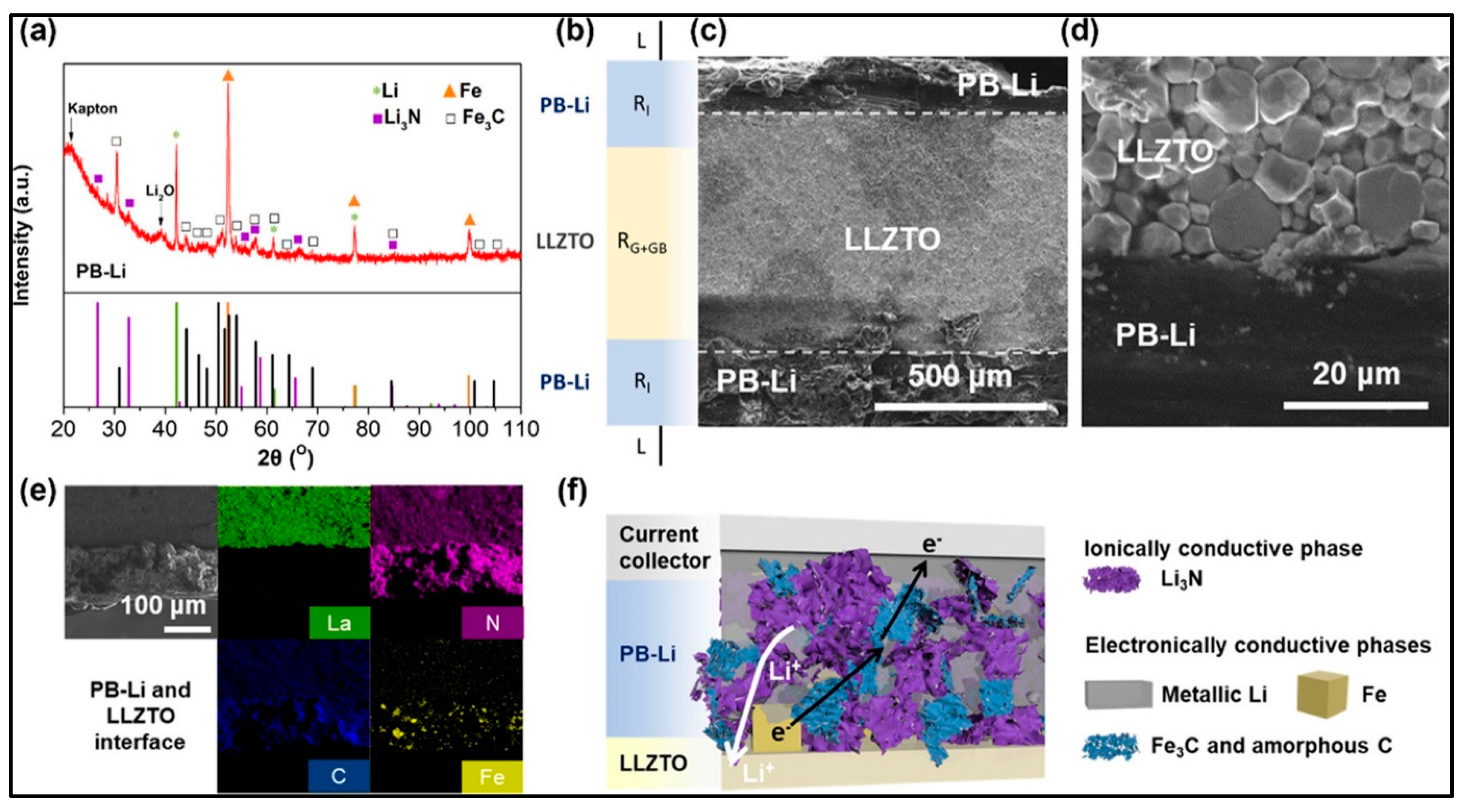
  118. Zhong, Y.; Cao, C.; Tadé, M.O.; Shao, Z. Ionically and Electronically Conductive Phases in a Composite Anode for High-Rate and Stable Lithium Stripping and Plating for Solid-State Lithium Batteries. ACS Appl. Mater. Interfaces 2022, 14, 38786–38794. [Google Scholar] [CrossRef] [PubMed]
  119. Vidakis, N.; Petousis, M.; Mangelis, P.; Maravelakis, E.; Mountakis, N.; Papadakis, V.; Neonaki, M.; Thomadaki, G. Thermomechanical Response of Polycarbonate/Aluminum Nitride Nanocomposites in Material Extrusion Additive Manufacturing. Materials 2022, 15, 8806. [Google Scholar] [CrossRef]
  120. Zhou, D.; Ren, G.X.; Zhang, N.; Yu, P.F.; Zhang, H.; Zheng, S.; Tian, Z.W.; Du, S.Y.; Chen, J.X.; Liu, X.S. Garnet Electrolytes with Ultralow Interfacial Resistance by SnS2Coating for Dendrite-Free All-Solid-State Batteries. ACS Appl. Energy Mater. 2021, 4, 2873–2880. [Google Scholar] [CrossRef]
  121. Zhu, P.; Yan, C.; Zhu, J.; Zang, J.; Li, Y.; Jia, H.; Dong, X.; Du, Z.; Zhang, C.; Wu, N.; et al. Flexible Electrolyte-Cathode Bilayer Framework with Stabilized Interface for Room-Temperature All-Solid-State Lithium-Sulfur Batteries. Energy Storage Mater. 2019, 17, 220–225. [Google Scholar] [CrossRef]
  122. Dai, X.; Zou, K.; Jing, W.; Xu, P.; Sun, J.; Guo, S.; Tan, Q.; Liu, Y.; Zhou, T.; Chen, Y. A Dual-Functional Interlayer for Li-S Batteries Using Carbon Fiber Film Cladded Electron-Deficient Li2B4O7. J. Mater. Chem. A 2022, 10, 16152–16162. [Google Scholar] [CrossRef]
  123. Yu, X.; Bi, Z.; Zhao, F.; Manthiram, A. Polysulfide-Shuttle Control in Lithium-Sulfur Batteries with a Chemically/Electrochemically Compatible NaSICON-Type Solid Electrolyte. Adv. Energy Mater. 2016, 6, 1601392. [Google Scholar] [CrossRef]
  124. Yao, X.; Huang, N.; Han, F.; Zhang, Q.; Wan, H.; Mwizerwa, J.P.; Wang, C.; Xu, X. High-Performance All-Solid-State Lithium–Sulfur Batteries Enabled by Amorphous Sulfur-Coated Reduced Graphene Oxide Cathodes. Adv. Energy Mater. 2017, 7, 1602923. [Google Scholar] [CrossRef]
  125. Wang, S.; Zhang, Y.; Zhang, X.; Liu, T.; Lin, Y.H.; Shen, Y.; Li, L.; Nan, C.W. High-Conductivity Argyrodite Li6PS5Cl Solid Electrolytes Prepared via Optimized Sintering Processes for All-Solid-State Lithium-Sulfur Batteries. ACS Appl. Mater. Interfaces 2018, 10, 42279–42285. [Google Scholar] [CrossRef] [PubMed]
  126. Umeshbabu, E.; Zheng, B.; Zhu, J.; Wang, H.; Li, Y.; Yang, Y. Stable Cycling Lithium-Sulfur Solid Batteries with Enhanced Li/Li10GeP2S12 Solid Electrolyte Interface Stability. ACS Appl. Mater. Interfaces 2019, 11, 18436–18447. [Google Scholar] [CrossRef]
  127. Wan, H.; Liu, S.; Deng, T.; Xu, J.; Zhang, J.; He, X.; Ji, X.; Yao, X.; Wang, C. Bifunctional Interphase-Enabled Li10GeP2S12Electrolytes for Lithium-Sulfur Battery. ACS Energy Lett. 2021, 6, 862–868. [Google Scholar] [CrossRef]
  128. Xia, Y.; Li, J.; Zhang, J.; Zhou, X.; Huang, H.; He, X.; Gan, Y.; Xiao, Z.; Zhang, W. Yttrium Stabilized Argyrodite Solid Electrolyte with Enhanced Ionic Conductivity and Interfacial Stability for All-Solid-State Batteries. J. Power Sources 2022, 543, 231846. [Google Scholar] [CrossRef]
  129. Qian, J.; Jin, B.; Li, Y.; Zhan, X.; Hou, Y.; Zhang, Q. Research Progress on Gel Polymer Electrolytes for Lithium-Sulfur Batteries. J. Energy Chem. 2021, 56, 420–437. [Google Scholar] [CrossRef]
  130. Han, D.D.; Liu, S.; Liu, Y.T.; Zhang, Z.; Li, G.R.; Gao, X.P. Lithiophilic Gel Polymer Electrolyte to Stabilize the Lithium Anode for a Quasi-Solid-State Lithium-Sulfur Battery. J. Mater. Chem. A 2018, 6, 18627–18634. [Google Scholar] [CrossRef]
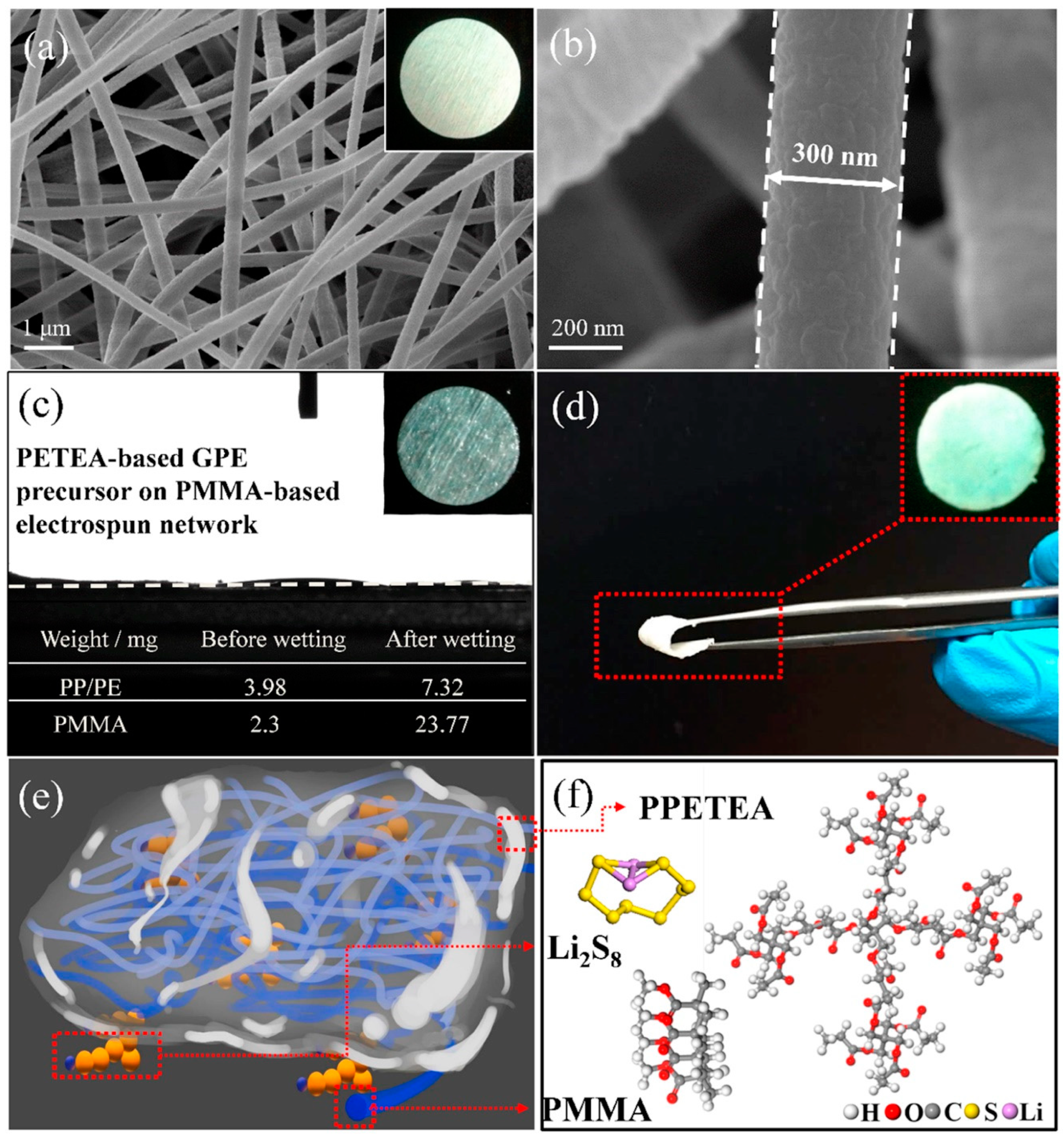
  131. Sheng, J.; Zhang, Q.; Sun, C.; Wang, J.; Zhong, X.; Chen, B.; Li, C.; Gao, R.; Han, Z.; Zhou, G. Crosslinked Nanofiber-Reinforced Solid-State Electrolytes with Polysulfide Fixation Effect Towards High Safety Flexible Lithium–Sulfur Batteries. Adv. Funct. Mater. 2022, 32, 2203272. [Google Scholar] [CrossRef]
  132. Liu, M.; Jiang, H.R.; Ren, Y.X.; Zhou, D.; Kang, F.Y.; Zhao, T.S. In-Situ Fabrication of a Freestanding Acrylate-Based Hierarchical Electrolyte for Lithium-Sulfur Batteries. Electrochim. Acta 2016, 213, 871–878. [Google Scholar] [CrossRef]
  133. Lin, Y.; Wang, X.; Liu, J.; Miller, J.D. Natural Halloysite Nano-Clay Electrolyte for Advanced All-Solid-State Lithium-Sulfur Batteries. Nano Energy 2017, 31, 478–485. [Google Scholar] [CrossRef]
  134. Liang, Y.; Chen, N.; Qu, W.; Yang, C.; Li, L.; Wu, F.; Chen, R. Vertical Channels Design for Polymer Electrolyte to Enhance Mechanical Strength and Ion Conductivity. ACS Appl. Mater. Interfaces 2021, 13, 42957–42965. [Google Scholar] [CrossRef]
  135. Xie, P.; Yang, R.; Zhou, Y.; Zhang, B.; Tian, X. Rationally Designing Composite Gel Polymer Electrolyte Enables High Sulfur Utilization and Stable Lithium Anode. Chem. Eng. J. 2022, 450, 138195. [Google Scholar] [CrossRef]
  136. Ellis, B.L.; Nazar, L.F. Sodium and Sodium-Ion Energy Storage Batteries. Curr. Opin. Solid State Mater. Sci. 2012, 16, 168–177. [Google Scholar] [CrossRef]
  137. Delmas, C. Sodium and Sodium-Ion Batteries: 50 Years of Research. Adv. Energy Mater. 2018, 8, 1703137. [Google Scholar] [CrossRef]
  138. Duffner, F.; Kronemeyer, N.; Tübke, J.; Leker, J.; Winter, M.; Schmuch, R. Post-Lithium-Ion Battery Cell Production and Its Compatibility with Lithium-Ion Cell Production Infrastructure. Nat. Energy 2021, 6, 123–134. [Google Scholar] [CrossRef]
  139. Hwang, J.Y.; Myung, S.T.; Sun, Y.K. Sodium-Ion Batteries: Present and Future. Chem. Soc. Rev. 2017, 46, 3529–3614. [Google Scholar] [CrossRef] [PubMed]
  140. Kim, I.; Kim, C.H.; Choi, S.H.; Ahn, J.P.; Ahn, J.H.; Kim, K.W.; Cairns, E.J.; Ahn, H.J. A Singular Flexible Cathode for Room Temperature Sodium/Sulfur Battery. J. Power Sources 2016, 307, 31–37. [Google Scholar] [CrossRef]
  141. Adelhelm, P.; Hartmann, P.; Bender, C.L.; Busche, M.; Eufinger, C.; Janek, J. From Lithium to Sodium: Cell Chemistry of Room Temperature Sodium-Air and Sodium-Sulfur Batteries. Beilstein J. Nanotechnol. 2015, 6, 1016–1055. [Google Scholar] [CrossRef]
  142. Tanibata, N.; Deguchi, M.; Hayashi, A.; Tatsumisago, M. All-Solid-State Na/S Batteries with a Na3PS4 Electrolyte Operating at Room Temperature. Chem. Mater. 2017, 29, 5232–5238. [Google Scholar] [CrossRef]
  143. Fan, X.; Yue, J.; Han, F.; Chen, J.; Deng, T.; Zhou, X.; Hou, S.; Wang, C. High-Performance All-Solid-State Na-S Battery Enabled by Casting-Annealing Technology. ACS Nano 2018, 12, 3360–3368. [Google Scholar] [CrossRef]
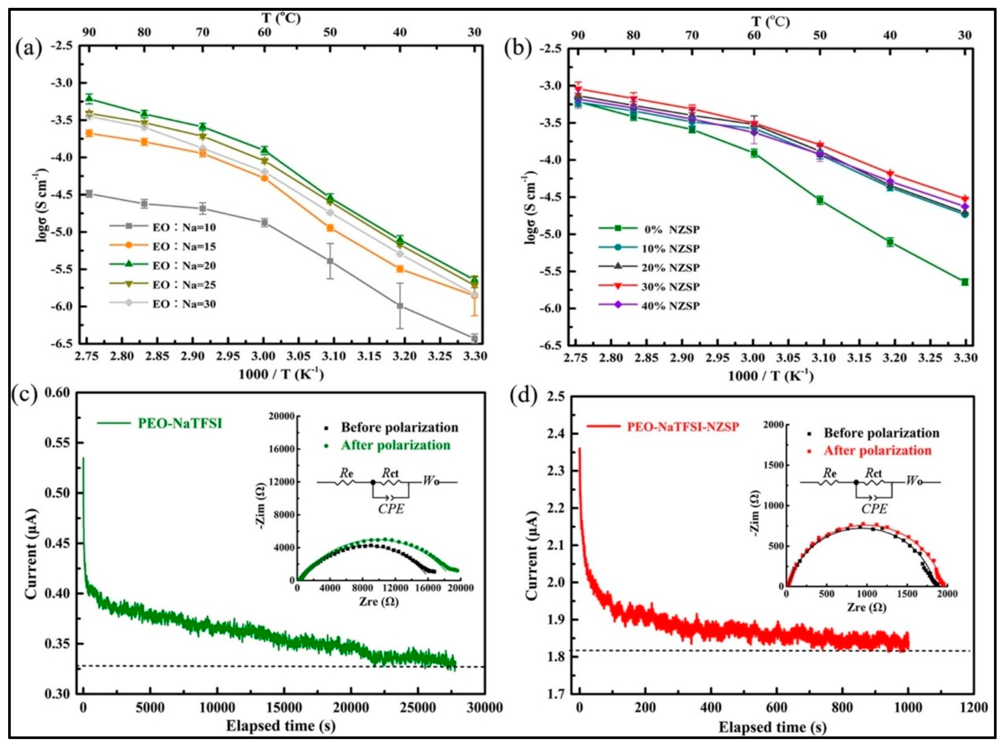
  144. Ge, Z.; Li, J.; Liu, J. High Sodium Ion Mobility of PEO-NaTFSI-Na3Zr2Si2PO12 Composite Solid Electrolyte for All-Solid-State Na-S Battery. ChemistrySelect 2022, 7, e20220062. [Google Scholar] [CrossRef]
  145. Yue, J.; Han, F.; Fan, X.; Zhu, X.; Ma, Z.; Yang, J.; Wang, C. High-Performance All-Inorganic Solid-State Sodium-Sulfur Battery. ACS Nano 2017, 11, 4885–4891. [Google Scholar] [CrossRef] [PubMed]
  146. Jhang, L.-J.; Wang, D.; Silver, A.; Li, X.; Reed, D.; Wang, D. Stable All-Solid-State Sodium-Sulfur Batteries for Low-Temperature Operation Enabled by Sodium Alloy Anode and Confined Sulfur Cathode. Nano Energy 2023, 105, 107995. [Google Scholar] [CrossRef]
Figure 1. (a) Schematic representation of Li-S battery comprising two different cathode (C/S and CoNi2S4/S), lithium metal as the anode and ether-based electrolyte, (b) A cyclic voltammetry diagram of a liquid electrolyte-based Li-S cell with conventional C/S cathode. (Reprinted with permission from [41]); Copyright 2020, ACS Appl. Mater. Interfaces 2020, 12, 28120–28128.)
Batteries 09 00110 g001
Figure 2. Schematic representation of HT Na/S battery with molten solid electrolyte, molten sodium anode and molten sulfur cathode.
Batteries 09 00110 g002
Figure 4. Schematic representation of challenges in metal (Li/Na)–sulfur batteries. (Reprinted with permission from [75]; Copyright 2019, 2018, Springer Singapore, 2018.)
Batteries 09 00110 g004
Figure 5. Schematic representation of all-solid-state metal (Li/Na) sulfur batteries.
Batteries 09 00110 g005
Figure 6. (a) X-ray diffraction pattern of synthesized PB-Li-anode; (b) explanatory presentation; (c,d) Scanning electron microscopy image; (e) EDS Mapping; (f) explanation of ionic and electronic pathways. (Reprinted with permission from [118]; Copyright 2022, ACS Appl. Mater. Interfaces 2022, 14, 38786–38794).
Batteries 09 00110 g006
Figure 7. (a) Schematic representation of the all-solid-state lithium sulfur cell with NASICON-type (Li1+xYxZr2-x(PO4)3 membrane as a solid electrolyte/separator; (b) voltage versus time charge/discharge curve; (c) cyclic voltammetry of the cell; (d) galvanostatic charge/discharge curve; (e) discharge capacity versus number of cycle; (f) coulombic efficiency versus number of cycle. (Reprinted with permission from [123]; Copyright 2016, Adv. Energy Mater. 2016, 6).
Batteries 09 00110 g007
Figure 8. (A) The schematic representation of the quasi-solid-state lithium–sulfur cell comprising AB cathode, LGPS solid electrolyte and lithium metal as the anode; (B) first galvanostatic charge/discharge curves for different S@C composite cathode at current rate 83.5 mAg−1; (C) the specific discharge capacity versus number of cycles of Li-S cell with various cathode; (D) the electrochemical impedance spectroscopy of the Li-S cell with various cathodes. (Reprinted with permission from [126]; Copyright 2019, ACS Appl. Mater. Interfaces 2019, 11, 18436–18447).
Batteries 09 00110 g008
Figure 9. (a,b) Scanning electron microscopy image of PMMA-based electrospun fiber network; (c) uptake ability of the PMMA-based electrospun fiber network GPE; (d) optical image of AHE; (e,f) schematic representation of atomic configurations of AHE. (Reprinted with permission from [132]; Copyright 2016, Electrochim. Acta 2016, 213, 871–878).
Batteries 09 00110 g009
Figure 10. (a) Schematic representation of the synthesis procedure of Na2S-Na3PS4-CMK-3 nanocomposites cathode; (b) Na2S and P2S5 phase diagram; (c) Na2S-Na3PS4-CMK-3 nanocomposites. (Reprinted with permission from [143]; Copyright 2018, ACS Nano 2018, 12, 3360–3368).
Batteries 09 00110 g010
Figure 11. (a) Ionic conductivity of PEO–NaTFSI-based electrolyte at different EO:Na+ ratios; (b) ionic conductivity of PEO–NaTFSI/Na3Zr2Si2PO12 at various weight ratios of Na3Zr2Si2PO12; (c) Ac impedance and chronoamperometry of Na|| PEO–NaTFSI ||Na cell; (d) equivalent circuit used to fit the impedance data. (Reprinted with permission from [144]; Copyright 2022, ChemistrySelect 2022, 7).
Batteries 09 00110 g011
Figure 12. (a) Galvanostatic charge/discharge profile of all-solid-state Na-S cell with NPS-micro-Na2S-C composite cathode at various current rates; (b) galvanostatic charge/discharge profile of all-solid-state Na-S cell with NPS-nano-Na2S-C composite cathode at various current rate; (c) rate capability of the all-solid-state Na-S cell with two different composite cathodes at 60 °C; (d) the electrochemical impedance spectroscopy (EIS) of the cell with two different composite cathodes. (Reprinted with permission from [145]; Copyright 2017, ACS Nano 2017, 11, 4885–4891).
Batteries 09 00110 g012
Table 1. Comparative study of different electrolyte systems discussed in the present review. Reprinted with permission from [113,114].
ElectrolyteCompositionIonic Conductivity (Scm−1)Mechanical PropertiesAdvantagesDisadvantages
Inorganic solid electrolyteOxide-Based (LISICON, NASICON, Garnet etc.)
Sulfide-Based (Argyrodite, Thio-LISICON, Halide-Based etc.)
10−5–10−4StrongWide electrochemical window, High ionic
conductivity,
excellent thermal
stability,
Poor interface
Gel-Polymer electrolyteLiquid electrolyte confined inside polymer matrix~10−3softHigh ionic
conductivity, good interfacial property.
Reduction of polysulfide dissolution to some extent
Less mechanical
stability, less thermal stability
Solid-Polymer ElectrolytePolymer + salt + additive<10−5GoodPoor interfacial property, thermally stable,
Reduces polysulfide dissolution
Less ionic
conductivity; Less mechanical stability
Composite electrolytePolymer/organic
fiber + inorganic
10−5–10−4StrongPoor interface, thermally stable,
reduction of polysulfide dissolution,
reduction in dendrite growth
Low ionic
conductivity poor
thermal stability
Disclaimer/Publisher’s Note: The statements, opinions and data contained in all publications are solely those of the individual author(s) and contributor(s) and not of MDPI and/or the editor(s). MDPI and/or the editor(s) disclaim responsibility for any injury to people or property resulting from any ideas, methods, instructions or products referred to in the content.

