Article

An Autonomous Human Following Caddie Robot with High-Level Driving Functions

1
Department of Robotics Engineering, DGIST (Daegu Gyeongbuk Institute of Science and Technology), Daegu 711-785, Korea
2
School of Mechanical Engineering, Yeungnam University, Gyeongsan 712-749, Korea
*
Authors to whom correspondence should be addressed.
Electronics 2020, 9(9), 1516; https://doi.org/10.3390/electronics9091516
Submission received: 15 August 2020 / Revised: 4 September 2020 / Accepted: 10 September 2020 / Published: 15 September 2020
(This article belongs to the Special Issue Robots in Assisted Living)

Abstract

:
Nowadays, mobile robot platforms are utilized in various fields not only for transportation but also for other diverse services such as industrial, medical and, sports, etc. Mobile robots are also an emerging application as sports field robots, where they can help serve players or even play the games. In this paper, a novel caddie robot which can autonomously follow the golfer as well as provide useful information such as golf course navigation system and weather updates, is introduced. The locomotion of the caddie robot is designed with two modes: autonomous human following mode and manual driving mode. The transition between each mode can be achieved manually or by an algorithm based on the velocity, heading angle, and inclination of the ground surface. Moreover, the transition to manual mode is activated after a caddie robot has recognized the human intention input by hand. In addition, the advanced control algorithm along with a trajectory generator for the caddie robot are developed taking into consideration the locomotion modes. Experimental results show that the proposed strategies to drive various operating modes are efficient and the robot is verified to be utilized in the golf course.

1. Introduction

Interaction between humans and robots has become a major component in robot technologies, in addition to conventional industrial application oriented functions such as high speed, precision, and robustness which are customized to their repetitive tasks. For human assistive robots, the cooperation between human and robot is categorized into physical human-robot interaction [1] and indirect interaction such as human tracking task [2] providing useful information [3], and entertainment [4].
Recently in sports, there has been developments of robots that indirectly interact with humans even though their functions are limited to basic levels of sports activities such as catching a baseball [5], kicking a football [6], and even throwing the stone in a curling game [7]. In this regard, golf, being another popular sport, has had various robots being developed and applied for training sessions. The authors of [8] introduce a novel robot called ’RoboCup and Caddy Cord’ which is placed in the hole to return the golf ball back to the player automatically whereas [9] presents an autonomous mobile robot that can search, pick-up the golf ball, and return it to the player. Furthermore, in swing training, several devices [10,11] have also been developed to analyze the optimal swing speed and posture of the player at impact point of the golf ball, while in [12], a system which observes optimal position of golf ball on the grass is proposed. In addition, the authors of [13] introduces an autonomous grass mowing robot which uses a high-accuracy local positioning system (LPS) for robot localization.
In golf, a person called caddie helps a player by carrying his/her bag and club, giving advises and supporting the player. Other roles of a caddie include; understanding the overall golf field, pin placement, club selection, as well as the obstacles of the golf course being played. However, the cost for professional caddies can be very high, and thus not all the players can afford them. Therefore, to reduce the cost and popularize the sport, autonomous caddies have been developed. For example, a conventional caddie robot that can autonomously follow a human based on the vision system is proposed in [14]. However, it is still at experimental level and has not been verified with the real application. In addition, some companies have commercialized an automatic caddie robot [15], however, the robot’s technical details are not well discussed.
Further, there are several researches about autonomous human following by mobile robots: A novel driving algorithm based on a camera is proposed in [16,17,18] for a wheel-based service robot that can carry baggage and follow a person. The visual controller for human following is comprised of a robust vision-based driving controller that generates the necessary motion command. In particular, the servo controller enables following humans with a constant distance from the human-based tracking error. In these articles, the controller to track a moving human in a 2-D plane was well constructed. However, the detailed formulation or experimental results related to the regulated distance between the human and the robot are not given. The authors of [19] proposed an algorithm for recognizing gaits for human following by observing the gait information from an RGB-D camera. The working sequence segmentation method is adopted in this recognition algorithm. However, the detailed motion control algorithm related to velocity during human following is not mentioned and how to distinguish between the gaits is also not well-described. The authors of [20] proposed a fast path planning robot that enables human following even in dynamic obstacles. The robot is equipped with various motion sensors including LIDAR and a 3D laser scanner to generate the local path. After generating an optimized path, the control algorithm tracks the path by using instantaneous center of rotation algorithm. Even though the algorithm can adjust the robot speed according to the human’s position and pace, it is limited to forward direction only and does not consider rotation and backward movements. The authors of [21] also proposed a visual-based human following algorithms in mobile robots. This mobile robot adopted a special wheel (Mecanum wheels) to generate arbitrary turning motion to follow the human directly.
In spite of these developments, the literature about caddie robots are mostly about information technologies such as recognition and mapping systems. The question of how to effectively control and drive the caddie robot autonomously in rough terrains is not well investigated. With this motivation, a commercial targeted wheel-based mobile human following caddie robot is introduced in this paper. In comparison with conventional human following mobile robot, the caddie robot can follow the human more effectively in various human walking situations and provide useful driving functions. In particular, the proposed robot has an autonomous driving mode which is subdivided into standby, aligning, and following modes, and a manual driving mode which is subdivided into stationary, constant torque, and constant velocity modes. These modes enable the caddie to navigate easily in rough golf field terrain conditions while carrying the golf bag, since each driving mode can be switched depending on the conditions that are defined by intuitive switching parameters. Moreover, the manual mode provides the player with an extra benefits like driving in complex situations such as narrow spaces, parking lots, areas with many obstacles or even driving for fun.
The contributions of this paper are summarized as follows: first, the caddie robot that can autonomously follow human, provide a manual driving mode and offer extra utilities to the human is introduced. Second, the operating modes which cover all the movement scenarios of the caddie robot in the golf field are proposed. Third, the switching parameters and conditions that reflect the situational factors and motion states of the robot are developed.
The rest of this paper is organized as follows: Section 2 describes the caddie robot and driving scenarios based on the operating modes while the driving algorithms which include motion controller and human intention recognition algorithm are introduced in Section 3. In Section 4, experimental results are discussed to evaluate the functions of the proposed caddie robot, and Section 5 contains the conclusion of this paper.

2. Description of the Caddie Robot

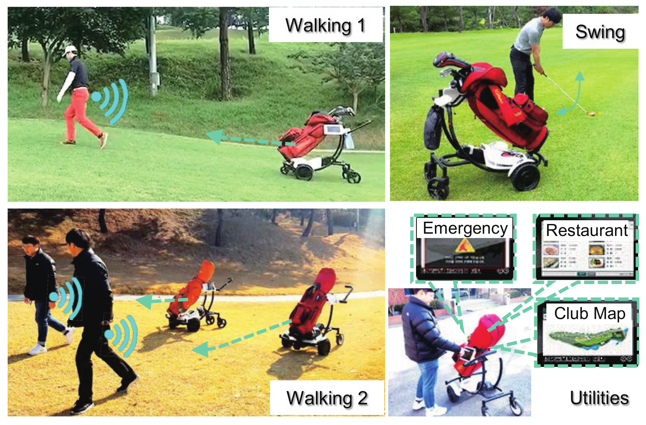
2.1. Functionalities of the Caddie Robot

Figure 1 illustrates the major functions of the caddie robot. The primary task is to autonomously follow the human while complying to abrupt stoppages, which is called the autonomous driving mode in this paper. Moreover, in special circumstances such as mentioned in the previous section, it can be switched to manual mode and be directly driven by human.
Other functions include; carrying the golf bag as it follows the human and providing useful information necessary for the game such as the number of players in the field, the map of the field ground, weather situation, emergency alerts, and restaurant information with the aid of an embedded tablet. To obtain this information, the caddie robot is designed to transmit and receive signals by using a repeater system that is already installed in the golf field.

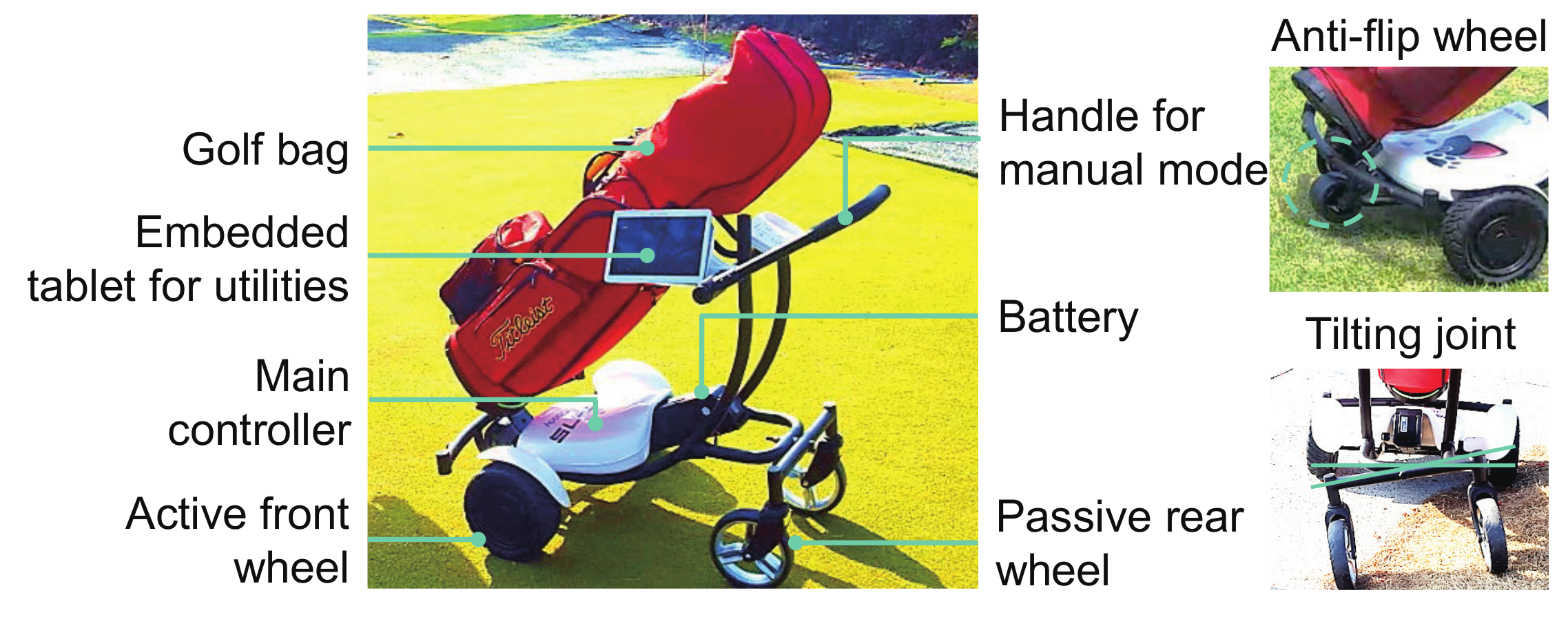
2.2. System Configuration and Operating Principle

For efficient movement on the field, the caddie robot consists of four wheeled mobile platform as shown in Figure 2, with two active front wheels for actuation and rear passive wheels. The additional small passive wheel is attached in the middle of the front chassis to prevent the caddie from flipping when descending a steep slope. Since the golf field has uneven terrain such as curved surface, the tilt mechanism with a tilting joint is installed to attenuate rolling motion.
For compact and energy efficient system, the main controller adopted STM32F407VG (manufactured by STMicroelectronics) as the main processor along with other on-board sensors which are IMU (Inertial Measurement Unit), gyro, and acceleration sensors to measure the motion of the caddie robot. Moreover, the remote controller based on a Radio Frequency (RF) signal to measure the distance between the robot and the player is preferred to the vision system for simplicity. All players should have the remote controller in their pocket or back side while playing. The overall size of the caddie robot is designed for one standard sized golf bag as the robot is for personal use.
Additionally, a handle, which is utilized during the manual driving mode, is attached to the chassis, and it can be folded during the autonomous driving mode. Detailed specifications of the caddie robot are listed in Table 1.

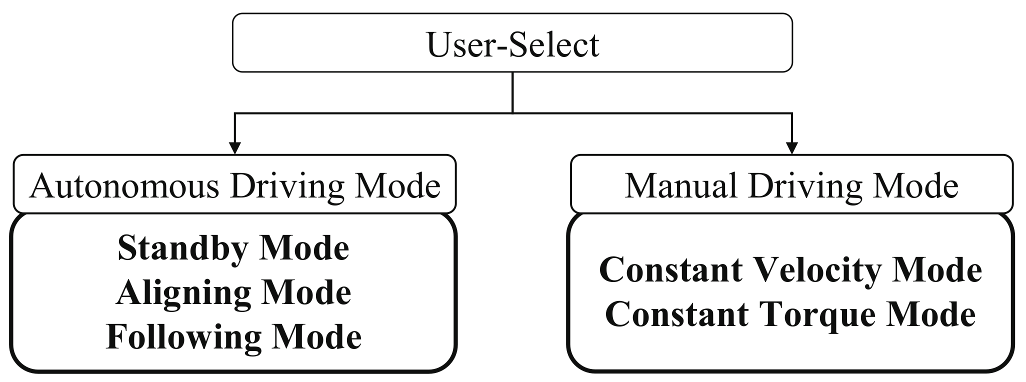
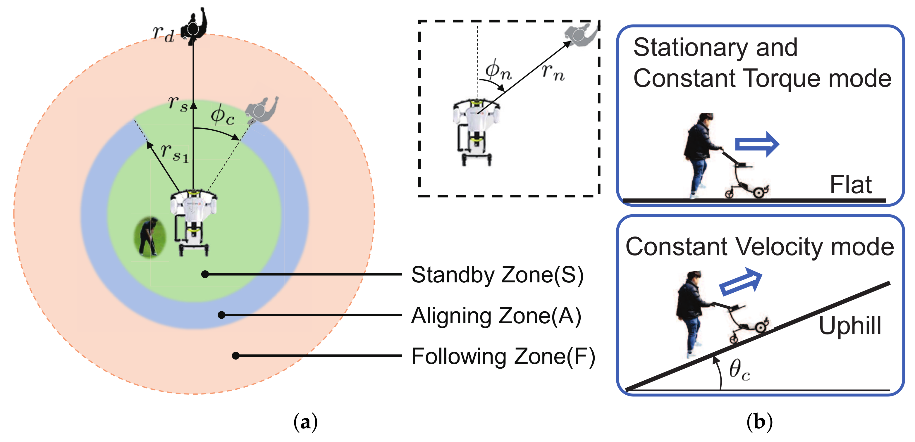
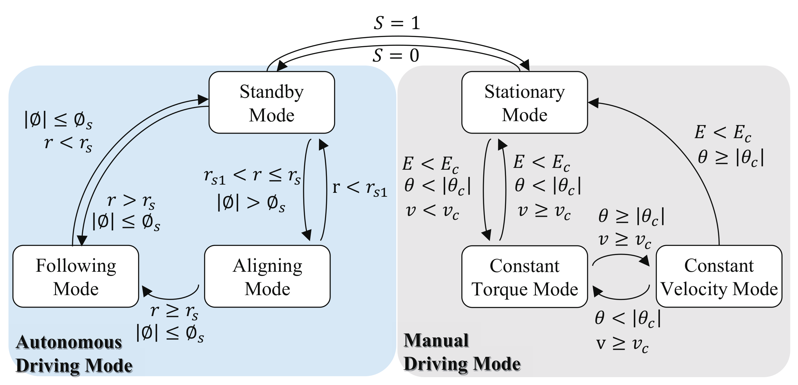
2.3. Driving Strategy for the Robot

The caddie robot is required to follow a human by itself keeping the specified distance from the human and to be manually driven by a human with the handle interface. To realize these motions, two different types of driving modes are proposed, (1) autonomous driving mode and (2) manual driving mode as shown in Figure 3.

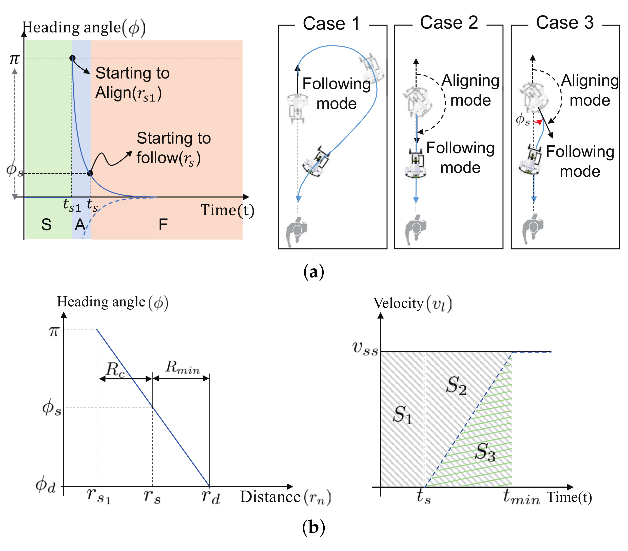
2.3.1. Autonomous Driving Mode

The autonomous driving mode is further subdivided into standby, aligning, and following sub-modes. Figure 4a illustrates how these sub-modes are determined basing on distance r and heading angle ϕ . The transition between these sub-modes is automatically activated by the player actions like swing, watching, walking, etc. Changes in the player actions are detected in terms of r and ϕ between the caddie and the human, which are measured using the RF signal from the remote controller possessed by the human.
The standby mode is activated when the player is within a specified remote distance r s 1 for actions like putting the ball, watching the ball, and making strategy, etc. The aligning and following modes, during which the robot follows the player are activated depending on variations in r and ϕ . Particularly, the aligning mode is activated when the current remote distance r n exceeds r s 1 , and the heading angle exceeds the predefined critical angle ϕ c . The following sub-mode is activated when the current heading angle ϕ n is less than ϕ c while the remote distance still exceeds r n > r s . The activation rules for these three sub-modes are summarized as follows,
  • Standby Mode: 0 < r n < r s 1
  • Aligning Mode: ( r s 1 < r n < r s ) ( | ϕ n | > ϕ c )
  • Following Mode: ( r s < r n < r f ) ( | ϕ n | > ϕ c )
where r f is the maximum measurable distance.

2.3.2. Manual Mode

The manual driving mode is subdivided into stationary, constant torque, and constant velocity sub-modes as shown in Figure 4b. The caddie robot is by default set to the stationary mode once switched to manual from autonomous mode. Different rule reflecting human intention is required for the switching between constant torque and constant velocity modes. Since the user holds the robot handle during the manual mode, the intention of the user can be transferred to the robot through the handle using a certain predefined pattern. To this end, a recognition algorithm is required to detect the pattern intended by the user. Hence, the root mean squared (RMS) error E is utilized as the parameter to determine whether the pattern applied by the user matches the predefined pattern or not. In addition, the switching between constant velocity and constant torque modes is required when the slope on which the robot is located is varying. Therefore, the geographic parameter, which is the slope angle information is adopted as the switching parameter in this case. These switching parameters including r n and ϕ c are listed in Table 2. The constant torque mode is activated when E < E c , θ < θ c , and the current velocity v is less than v c . This condition indicates that the robot is on the flat surface. When the robot is climbing uphill with larger slope angle than θ c as shown in Figure 4b, the current mode switches to constant velocity mode automatically. The switching conditions for constant torque and constant velocity modes are expressed as follows,
  • Constant Torque Mode: ( E < E c ) ( | θ | < θ c ) ( v < v c )
  • Constant Velocity Mode: ( v > v c ) ( | θ | > θ c )
In summary, Figure 5 illustrates the mode decision rules for the proposed caddie robot driving. First, switching between autonomous and manual is done by pressing the switch button on the robot where S = 1 means switching from autonomous to manual and S = 0 means vice versa.

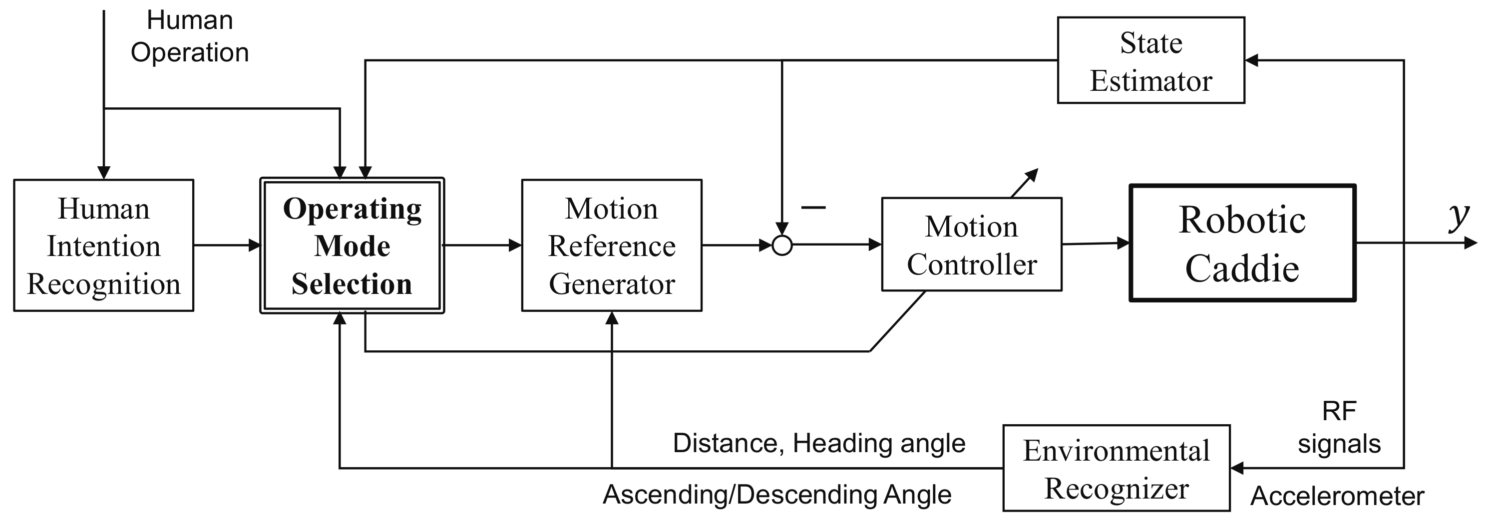
3. Driving and Control Algorithms

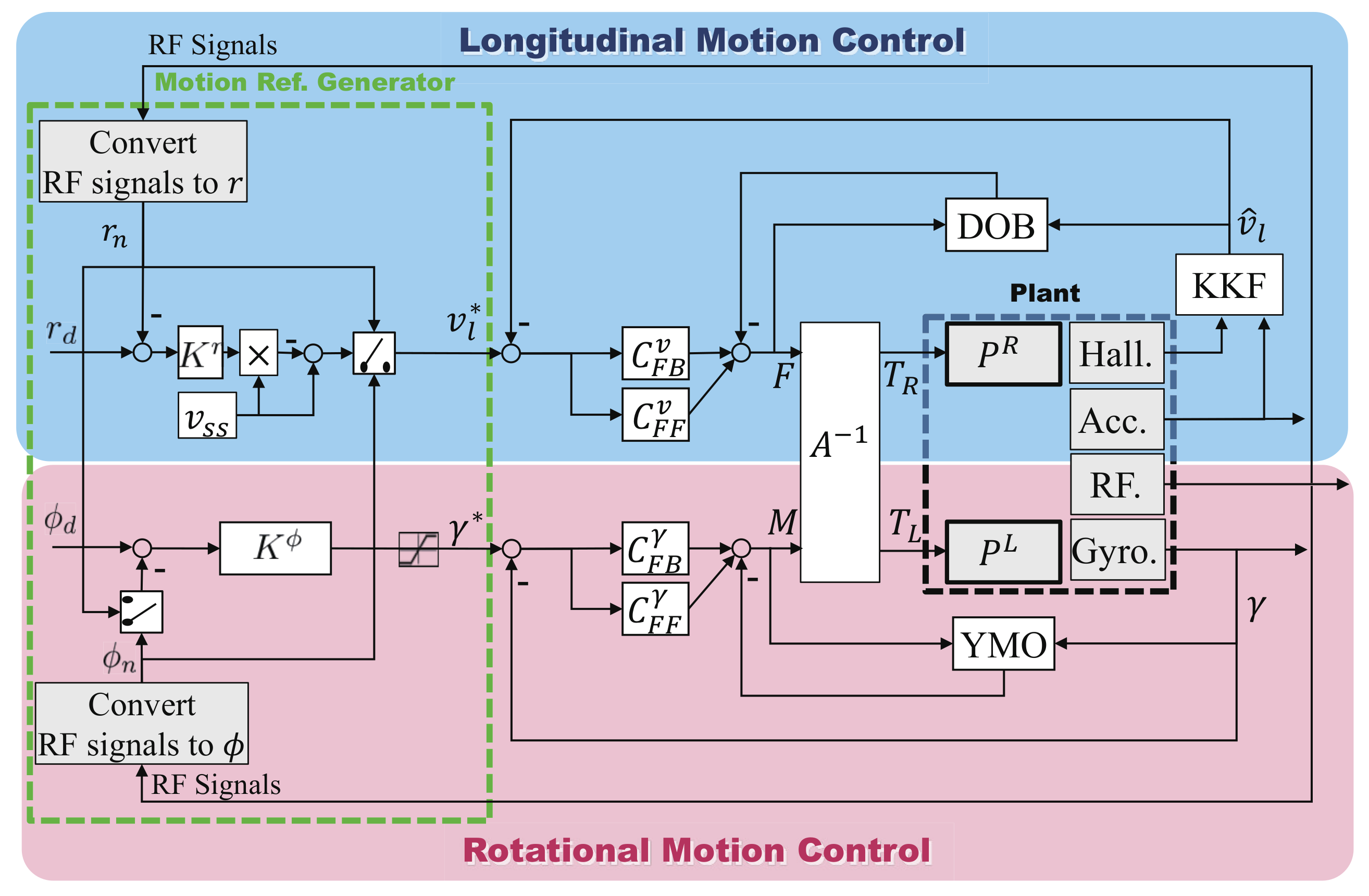
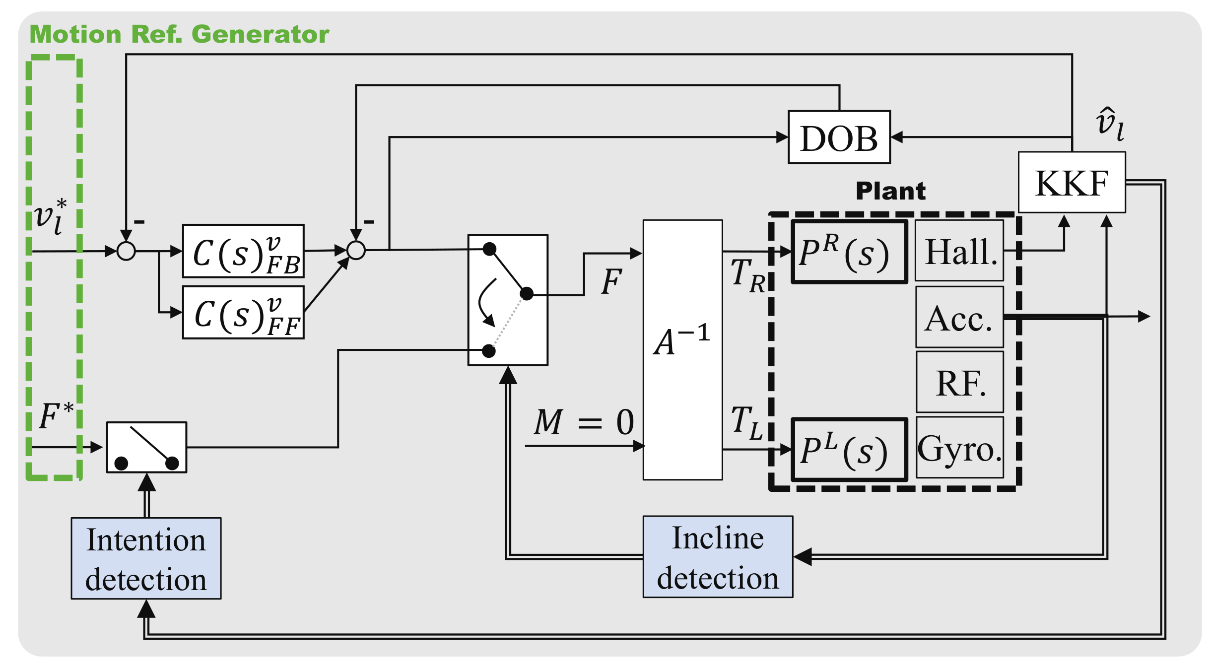
3.1. Overall Structure of Driving Controller for Caddie Robot

A whole algorithm suggested in this paper to realize all the driving modes described in Section 2.3 is shown in Figure 6. Notice that the information which the operation mode selection algorithm utilizes is from three components: (1) Human Intention recognition, and (2) Environment recognizer which is related to the external factors, and (3) State estimator which is related to the internal factors. In other words, the external factors such as human intention, distance and orientation from the user are processed with these components and utilized to determine the operation mode.
The switching parameters r, ϕ are obtained by utilizing the RF signals, in which there is a transformation from the Cartesian coordinates x, y measured by the RF sensor to the Polar coordinates as shown below.
r = 1 τ R F r s + 1 ( x s e n s o r 2 + y s e n s o r 2 ) ϕ = 1 τ R F ϕ s + 1 arctan 2 ( y s e n s o r , x s e n s o r )
The noise in the RF sensor signal is attenuated by utilizing a Low Pass Filter(LPF) with 2 Hz as the cut-off frequency. The slope angle θ is calculated from the accelerometer readings g s e n s o r as,
θ = arcsin ( g s e n s o r g m a x )
where g m a x is the gravitational constant.
Since the caddie robot does not have any encoder, an estimation algorithm is required to estimate the current velocity. The state estimator (Kinematic Kalman Filter) proposed in [22] is utilized which can estimate the velocity utilizing the Hall-effect sensor inside the driving wheels.

3.2. Control Configuration for Autonomous Driving Mode

To achieve robust driving even with unknown external perturbation, disturbance observer (DOB) [23] based velocity control is applied in this research. By applying DOB and Yaw Moment Observer (YMO) [24] in addition to the Proportional-Derivative (PD) controller in Figure 7, the caddie robot can eliminate any disturbance both in the longitudinal and rotational directions. Moreover, a feedforward controller is added to improve the response time such that the robot can respond to the user actions as fast as possible.
The controller blocks in Figure 7 are designed as follows.
C F B v = K p v + K d v s
C F B γ = K p γ + K d γ s
C F F v = M n s + D n τ Q v s + 1
C F F γ = J n s + B n τ Q γ s + 1
where M n , D n and J n , B n are the longitudinal and rotational nominal dynamics of the robot which are to be identified from the robot motion. KKF represents the Kinematic Kalman Filter proposed in [22,25] which estimates the longitudinal velocity using Hall-effect sensor (Hall.) and accelerometer (Acc.). The other parameters used in (3)–(6) are defined in Table 3.

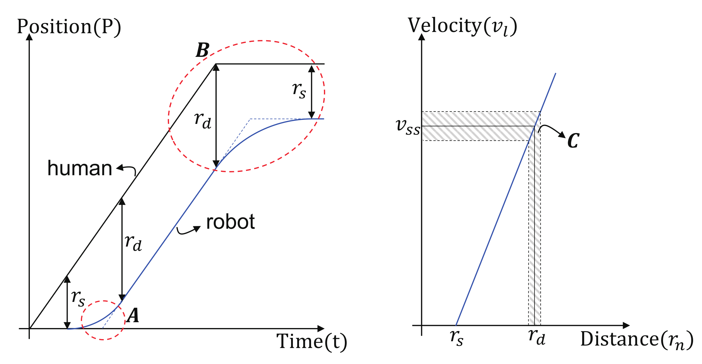
3.3. Velocity and Orientation Reference Generation Algorithm

It is important to note that the sampling times for the RF signals (x and y) and the controller are different, i.e., the sampling frequency of the RF signals is by far lower (<100 Hz) than the controller’s sampling period (1 ms), but the references v l * and γ * should be generated at every 1 ms for high-performance driving control. To address this problem, this paper proposes the calculation and utilization of the reference at velocity level not position level, even though it is the distance that should be regulated. The robot can follow the human with a constant distance when the velocity reference is set similar to the human walking velocity. In addition, the human velocity is assumed to be constant, and expressed as v s s , which can be set as a tuning parameter or replaced with actual measurement when it is available. To this end, the velocity reference for the caddie robot is designed as follows,
v l * = v s s K r ( r d r n ) ( r n > = r s ) 0 ( r n < r s )
where K r = v s s 1 r d r s is the gain, and this velocity reference generation algorithm is represented as blocks in Figure 7. r d is the desired gap distance within which the robot follows the human, r n is the current gap distance measured by the RF sensor, and r s is the threshold distance. The robot starts moving when r n > r s .
The Equation (7) can realize the following ideal motion of the robot; when the robot is near the user ( r n < r s ), the robot is controlled to stay, while the robot proceeds at the speed of (7) when the human is out of a certain range ( r n > = r s , where r s is the standby zone radius as illustrated in Figure 4). It is clear that the reference velocity reaches v s s when the gap distance r n becomes the desired gap distance r d . This ideal distance relationship is depicted in the right figure of Figure 8.
Suppose the human walks at a constant velocity as shown in the left figure of Figure 8 (the black solid line), the velocity of the robot (blue solid line) increases smoothly till it is equal to the human’s velocity (area A ). The expected human-robot distance with respect to time is depicted in the left figure of Figure 8, where it can be found that the robot stays at its position till the distance reaches r s , and the distance is kept less than r d by the proposed algorithm even when the user moves (area B ). The deceleration reference can be given by (7), as the robot approaches the human, the velocity reference decreases until it becomes 0 when r n approaches r s .
Aligning mode is required when the orientation of the robot is not towards the user. Figure 9a shows three different aligning strategies when the robot is oriented in the opposite direction with the user; Case 1: The robot performs translation and rotation concurrently to reorient with the human direction with a big turning radius. Case 2: The robot only rotates till its direction is aligned with the human’s. Case 3: The robot only rotates at first, but soon after it also starts translation such that it performs concurrent rotation and translation. Among these three strategies, Case 3 is adopted as the best aligning strategy; as it requires less time and trajectory till the heading angle of the robot is oriented with the human’s, as compared to Case 1 and Case 2.
The process to realize Case 3 is illustrated in the right figure of Figure 9a, where the change of the robot’s heading angle is illustrated with respect to time. The heading angle starts to rotate from a certain time t s 1 till it reaches the pre-determined value ϕ s . The robot starts translation from this point such that it can perform the aligning and following modes at the same time. The transition angle ϕ s can be selected taking into consideration the time taken for the aligning mode. The gap distance during aligning can be expressed as
R c = v s s t ϕ s = v s s ϕ s ϕ ˙ L i m
where t ϕ s which is time for the robot to align toward the human and ϕ ˙ L i m is the rotating velocity of the robot.
The relation between the alignment angle and gap distance is shown in Figure 9b. There are two requirements for this concurrent translation and rotation process: the orientation angle ϕ to be 0 when the gap distance r n becomes r d , and the velocity of the robot should reach v s s when the aligning process completes. Therefore, the time to reach v s s is calculated, basing on the constant acceleration pattern shown in Figure 9b. Moreover, this acceleration time can be reflected in the distance for the robot to go, which is denoted as R m i n . The following equation explains the relationship between v s s , acceleration time ( t m i n ), R m i n and the acceleration a m . Notice that the acceleration time t m i n is calculated as t m i n = v s s a l o n g i in (9).
R m i n = v s s t m i n 1 2 a m t m i n 2 = v s s 2 a m v s s 2 2 a m
The allowable gap distance r s considering R m i n is calculated as follows
r s = r d r m i n = r c + r s 1
Thus, the maximum alignment angle corresponding to r s is obtained as
ϕ s = r d r m i n r s 1 v s s ϕ ˙ L i m

3.4. Controller Design for the Manual Mode Operation

In the manual mode, the robot is controlled to provide a constant torque or a constant velocity. This manual model can be switched on using the mode select button (S = 1 of Figure 5) when the robot is in the stationary mode. Figure 10 shows the control block diagram of the manual driving mode, which consists of the constant velocity control and constant torque control. The constant velocity control is designed in the same way with the longitudinal velocity controller of the autonomous driving mode, while the rotational motion control is designed in the manual mode. This feature implies that only the longitudinal velocity is kept being in control in the manual mode while the rotational motion is not regulated by the controller. The constant torque control is a fully open loop type, and thus the assistive torque is generated by two motors in an open loop way, hence, the user will recognize a constant assistive force regardless of the driving condition.

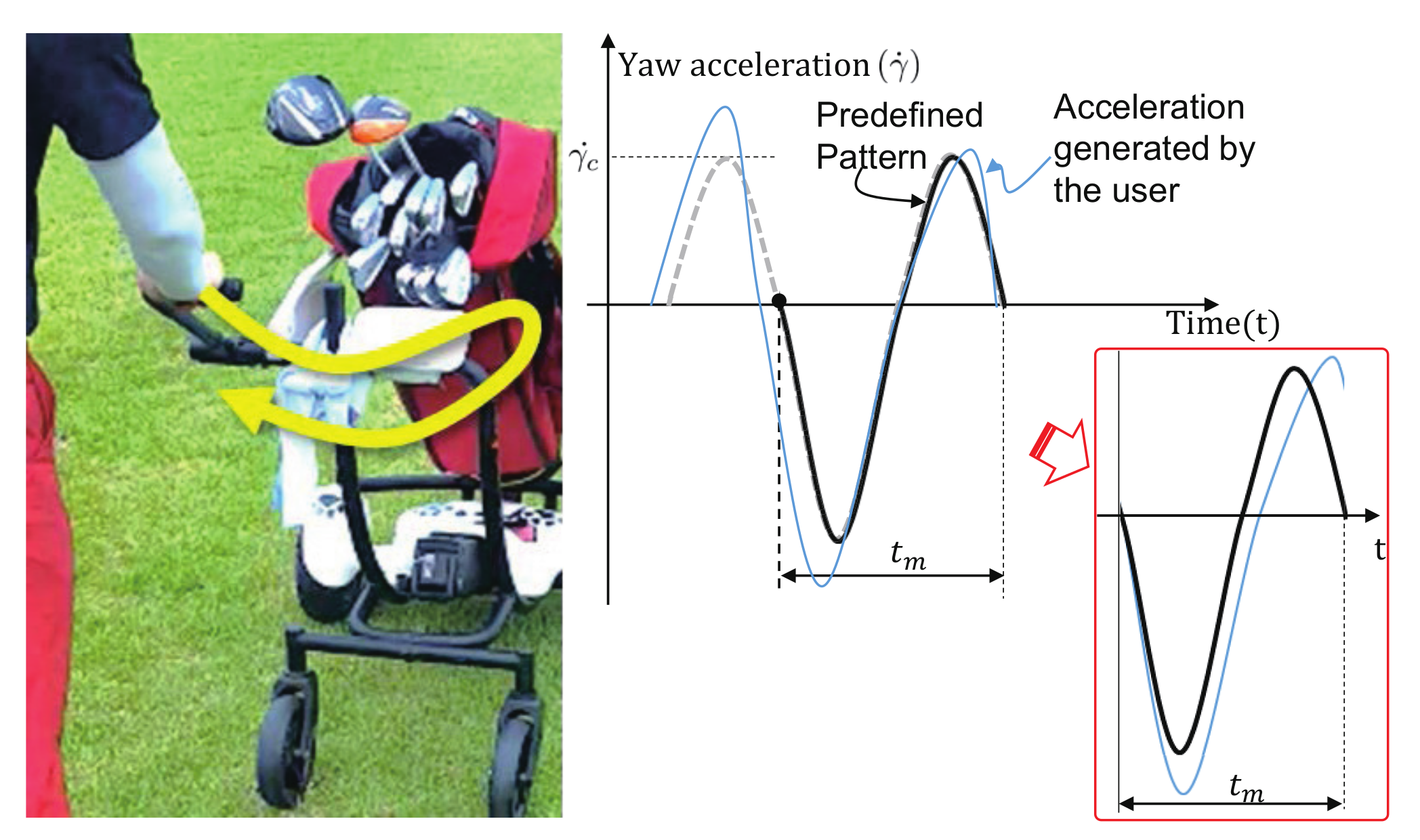
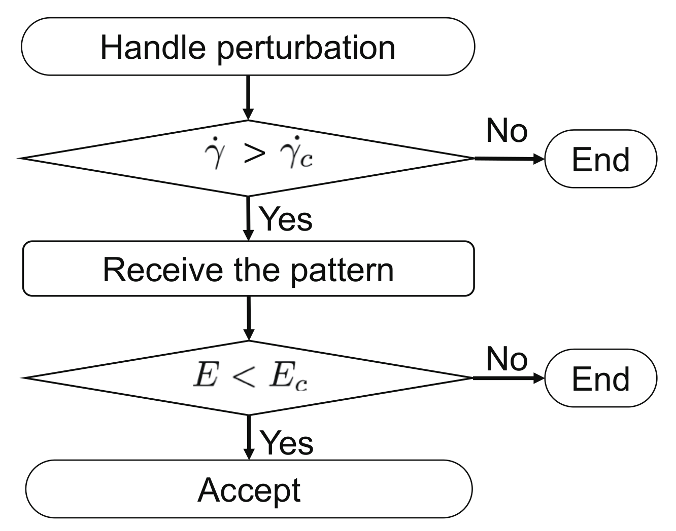
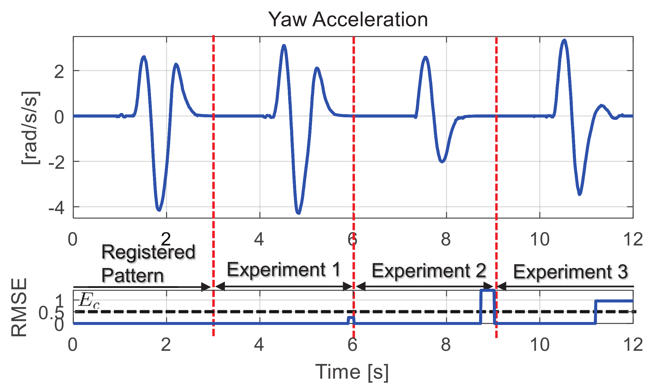
3.5. Human Intention Recognition Based on Yaw Motion

The human intention recognition algorithm is required for the robot to switch from stationary to constant torque sub-modes of the manual mode. The switching is done by the user perturbing the robot handle as shown in left Figure 11. To achieve perfect switching, a predefined pattern is registered and the mode change is activated by the intention detection in Figure 10 only when the perturbation pattern is close enough to this predefined pattern.
The bold solid line in Figure 11 indicates the yaw acceleration pattern utilized in the developed robot caddie, while the thin solid line shows an example of the measured yaw acceleration. The peak value ( γ ˙ c ) and the RMS error (E) between two are utilized as the most significant feature. Notice that the yaw acceleration is utilized as the trigger signal instead of the yaw rate. The whole intention-detection flow process is indicated in Figure 12, where γ ˙ c and E are utilized to determine the intention. Once activated, the intention-detector (Figure 12) measures the pattern at the moment when passing the zero point of the yaw acceleration during the measurement time t m .
Even though the constant torque mode can be effective enough for the user to appreciate the assistance, a different driving strategy is required when the caddie robot is on a slope. The force to push the robot on a slope is higher than the force required on the leveled ground. To deal with this issue, the constant velocity control mode is implemented, where the robot is controlled to follow the predefined velocity. The activation to the constant velocity mode depends on the slope angle: when a slope is detected during movement, i.e., slope angle is greater than θ c , a velocity controller is activated with a constant velocity reference while the yaw rate controller is de-activated for the ease of manipulation by the user.

4. Experimental Verification

Experiments are conducted to verify the operation of the proposed caddie robot. Moreover, the field test is performed in the golf course. All the control gains and parameters that are applied in this experiment are listed in Table 3.

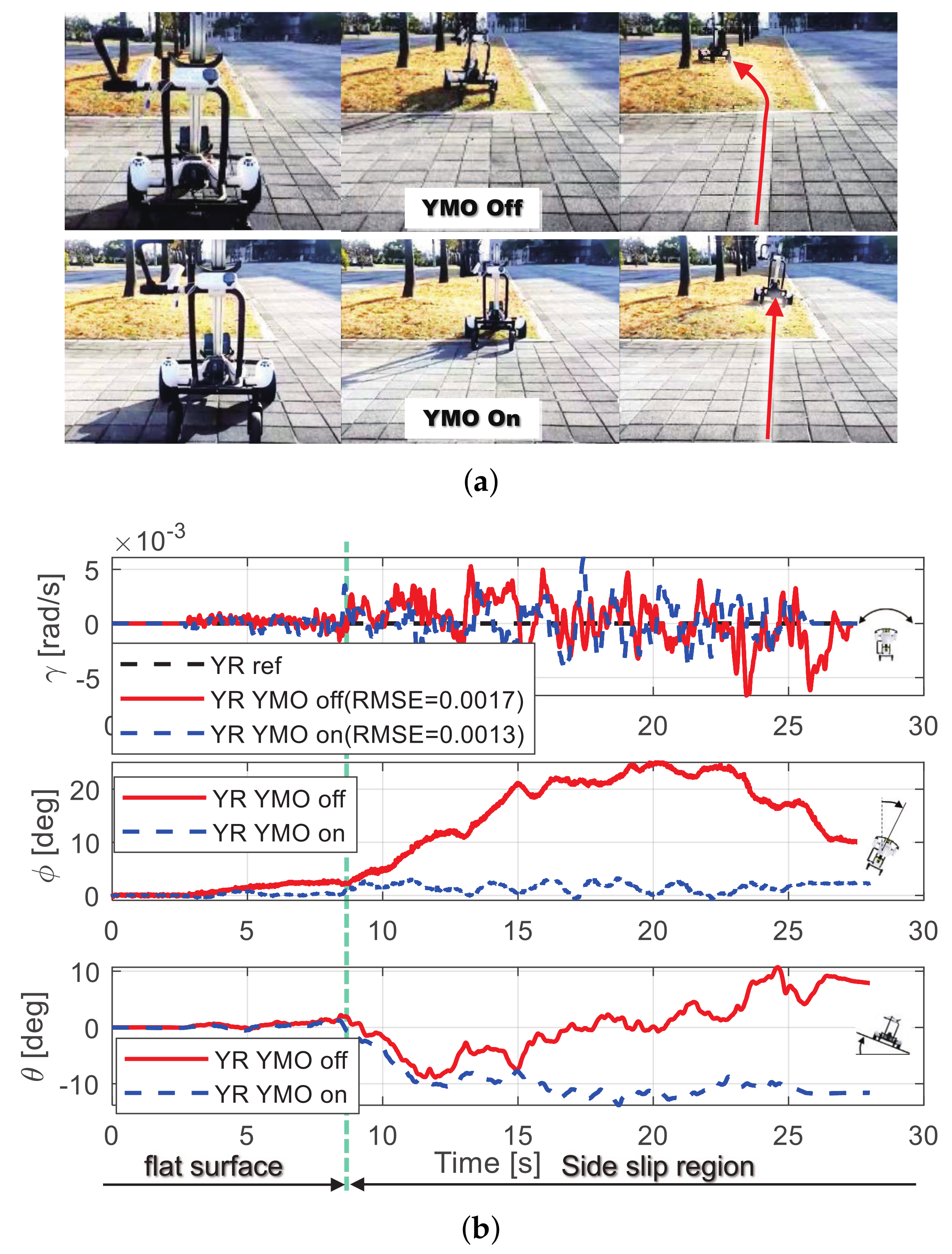
4.1. Verification of Driving Performance

The ability of the caddie robot to drive on rough terrains are tested since it is the fundamental function for the autonomous mode. Figure 13a shows the scene of the experiment where the robot is controlled to proceed straight on the side slope surface. To verify the effectiveness, two cases are considered: one without YMO and the other with YMO. The difference is not apparent in the measured yaw rate (the top figure of Figure 13b). However, a significant difference can be found in the heading angle: with YMO, the heading angle is maintained throughout the side slope region from 8 s in the graph, while it is not without YMO.
The effectiveness of the intention detection algorithm in Figure 12 is evaluated, and Figure 14 shows its experimental result after initial registration of the standard pattern by hand perturbation. In this algorithm, the value of the RMS error between initial standard pattern and trial pattern is set to 0.5 . By this criterion, only Trial 1 is recognized as the successful human interaction transmission.

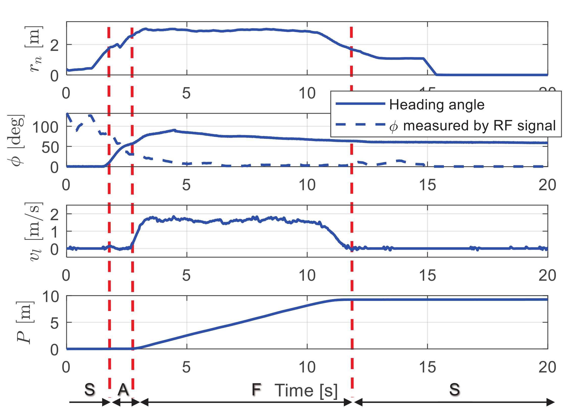
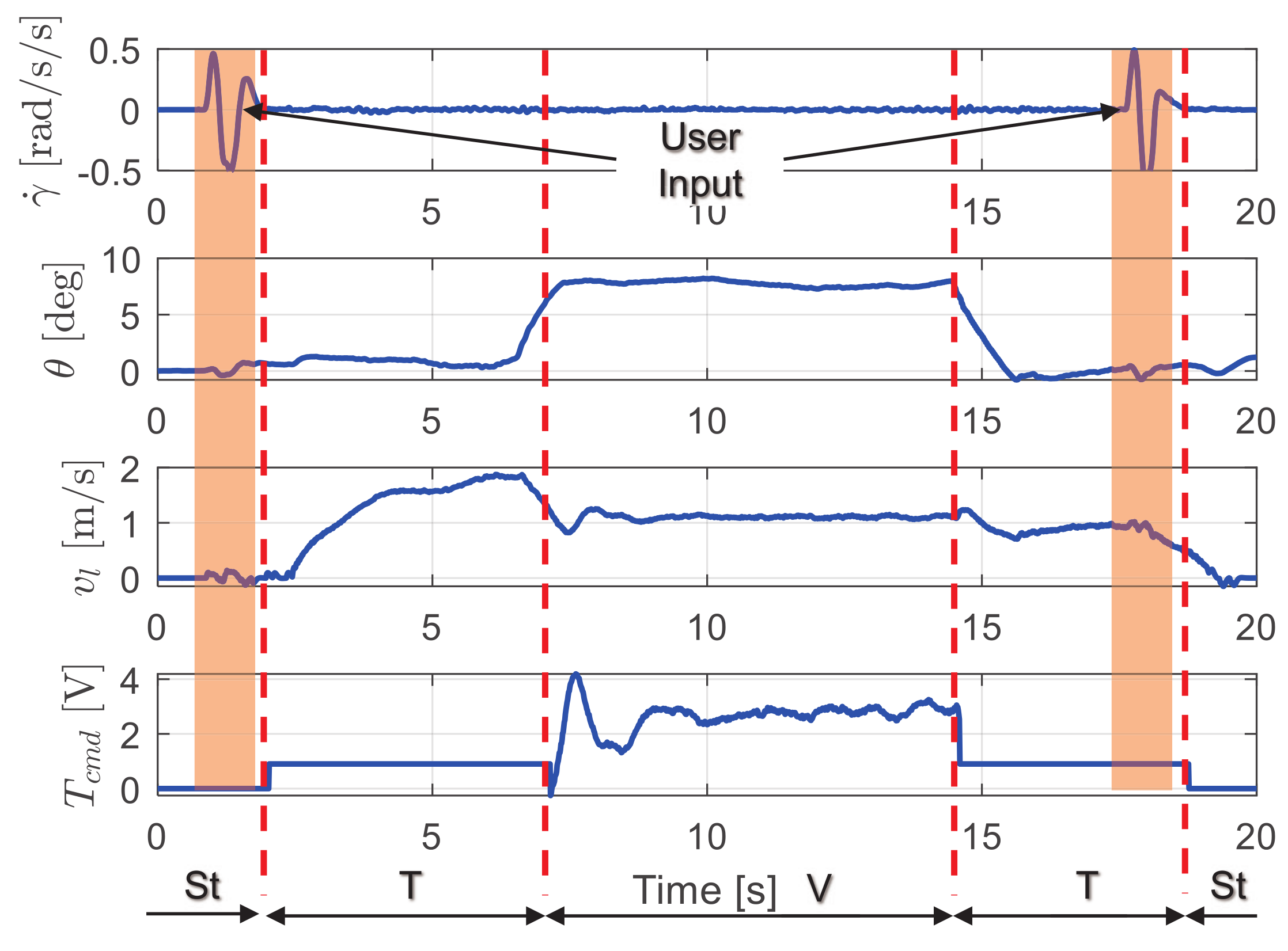
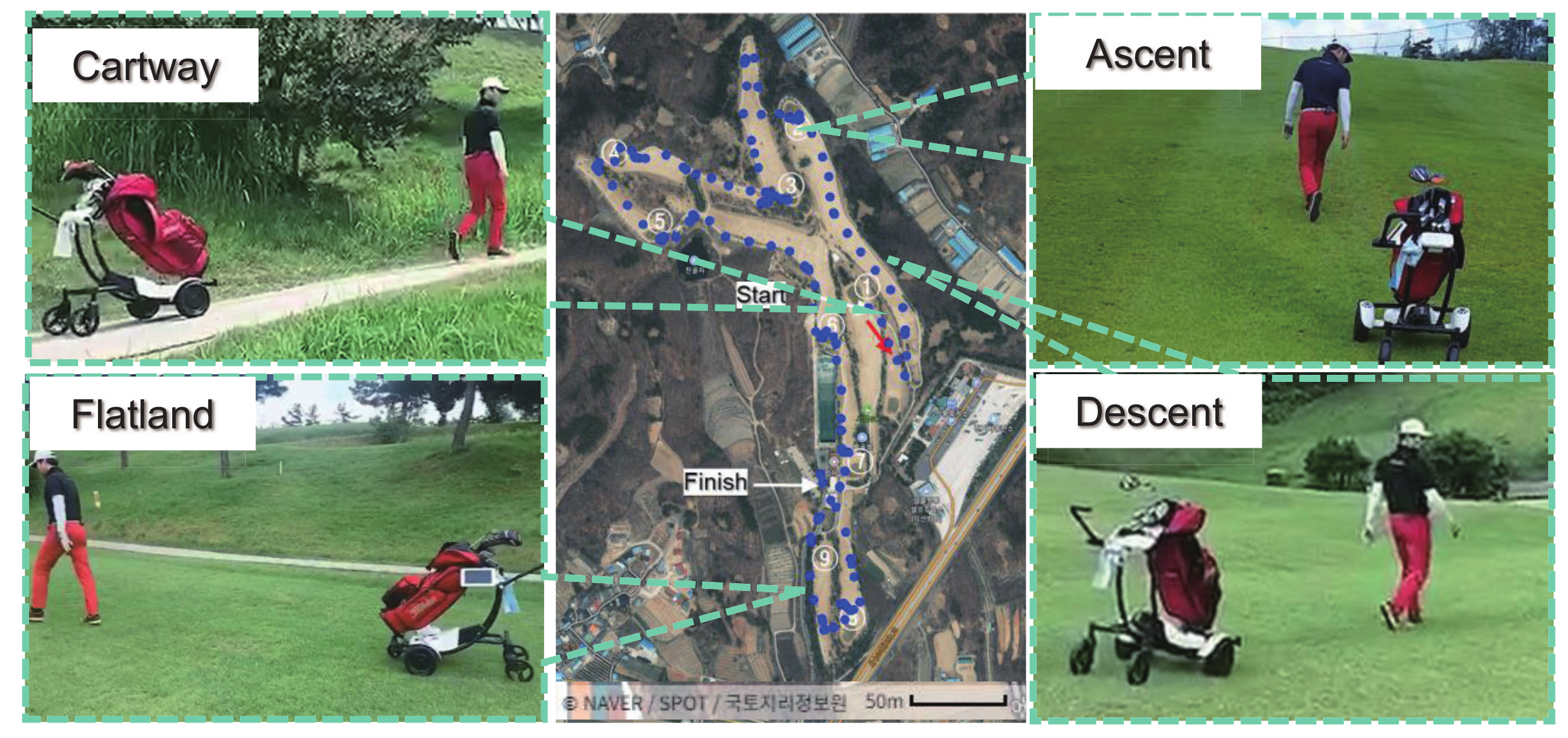
4.2. Experiment for the Whole Driving Scenario

In this experiment, mode switching is evaluated in both driving modes. The experimental scenario in autonomous driving mode is set such that the human starts walking from the robot with a big heading angle of 90 ) and Figure 15 shows the results. It can be observed that, as the human keeps walking, the current distance r n increases until it reaches r s 1 which is the standby mode and the robot speed is zero. Then, as soon as the distance passes r s 1 with a big heading angle ϕ n > ϕ s , the robot starts to rotate while maintaining its position (the aligning mode). Finally, when the distance passes r s and the heading angle aligned within ϕ s , the robot starts following the human with constant velocity (the following mode). Then, the human stops at 10 s but the robot does not stop and the velocity is decreased by the reference generator as shown in Figure 15. When the distance becomes less than r s with small ϕ , the robot stops (at 11.5 s) and the current mode switches again to standby mode.
Further, the manual driving mode scenario conducted and results are presented in Figure 16. As the first acceptable perturbation is given to the caddie robot by the user, the constant torque mode(T) is activated. Then the mode switches to the constant velocity mode (V) when the the robot is on the terrain with high slope angle, and when the second acceptable perturbation is given, the operating mode returns to the stationary mode (St) and the robot stops.
The caddie robot proposed in this paper is developed to navigate in the golf course in the same way as a golf cart. To evaluate its feasibility, the afield test is conducted in an actual golf course. Figure 17 shows the GPS trajectory of the caddie robot as it follows the human throughout the path in the field. Much as the golf course is an unstructured environment with complex terrain such as ascent road, descent road, cartway, flatland as shown in the Figure 17, the robot is able to successfully follow the human in all the path situations.

5. Conclusions

In this paper, a novel caddie robot that can serve the player while following him/her autonomously is proposed. In particular, the locomotion of the robot is realized by implementing the four wheel mobile platform for the effective movement in the unstructured golf field. Driving scenarios are designed by using the relative location between the robot and the human, who conducts various activities in the golf field. To deal with the play scenarios, the operating modes for the robot are defined and categorized to efficiently synchronize with human basing on the relative location. The manual mode is also given to the caddie robot on top of the autonomous mode. To switch between these modes the switching parameters are defined reflecting environmental conditions, human intentions, and operating conditions. To recognize the human intention by one-hand perturbation, the recognition algorithm is developed successfully. The operating mode switching, intention recognition based on pattern recognition algorithm as well as driving performance on the rough terrains were verified through several experiments in the grass environment and the actual golf field. Future research includes utilization of advanced technologies such as automatic obstacle detection, collision avoidance, and braking systems to improve on the safety of the caddie robot operation.

Author Contributions

J.H.C.; writing—original draft preparation and measurements and analyzed the experimental data. K.S.; writing—reviewing and editing. K.N.; Conceptualization and supervision S.O.; supervision. All authors have read and agreed to the published version of the manuscript.

Funding

This work has been supported in part by the Yeugnam University Research Grant 219A380011 and in part by the National Research Foundation of Korea (NRF) grant funded by the Korea government (MSIT) (NRF-2019R1A2C2011444).

Acknowledgments

The authors thank Baehee Lee who president of TTNG. The TTNG supported the manufacturing caddie robot and its experimental data.

Conflicts of Interest

The authors declare no conflict of interest.

References

  1. Haddadin, S.; Albu-Schäffer, A.; Hirzinger, G. Safe Physical Human-Robot Interaction: Measurements, Analysis and New Insights; Robotics Research, Kaneko, M., Nakamura, Y., Eds.; Springer: Berlin/Heidelberg, Germany, 2011; pp. 395–407. [Google Scholar]
  2. Morato, C.; Kaipa, K.N.; Zhao, B.; Gupta, S.K. Toward Safe Human Robot Collaboration by Using Multiple Kinects Based Real-Time Human Tracking. J. Comput. Inf. Sci. Eng. 2014, 14, 011006. [Google Scholar] [CrossRef]
  3. Roy, N.; Baltus, G.; Fox, D.; Gemperle, F.; Goetz, J.; Hirsch, T.; Margaritis, D.; Montemerlo, M.; Pineau, J.; Schulte, J.; et al. Towards personal service robots for the elderly. In Proceedings of the Workshop on Interactive Robots and Entertainment (WIRE 2000); 2000; Volume 25, p. 184. Available online: http://www.fore.robot.cc/papers/thrun.nursebot-early.pdf (accessed on 15 August 2020).
  4. Nakaoka, S.; Nakazawa, A.; Yokoi, K.; Ikeuchi, K. Leg motion primitives for a dancing humanoid robot. In Proceedings of the IEEE International Conference on Robotics and Automation, New Orleans, LA, USA, 26 April–1 May 2004; Volume 1, pp. 610–615. [Google Scholar]
  5. Cigliano, P.; Lippiello, V.; Ruggiero, F.; Siciliano, B. Robotic Ball Catching with an Eye-in-Hand Single-Camera System. IEEE Trans. Control Syst. Technol. 2015, 23, 1657–1671. [Google Scholar] [CrossRef] [Green Version]
  6. Widodo, F.A.; Mutijarsa, K. Design and implementation of movement, dribbler and kicker for wheeled soccer robot. In Proceedings of the 2017 International Conference on Information Technology Systems and Innovation (ICITSI), Bandung, Indonesia, 23–24 October 2017; pp. 200–205. [Google Scholar]
  7. Choi, J.H.; Song, C.; Kim, K.; Oh, S. Development of Stone Throwing Robot and High Precision Driving Control for Curling. In Proceedings of the 2018 IEEE/RSJ International Conference on Intelligent Robots and Systems (IROS), Madrid, Spain, 1–5 October 2018; pp. 2434–2440. [Google Scholar]
  8. Anderson, M. A new spin on an old toy. IEEE Spectr. 2009, 46, 18–19. [Google Scholar] [CrossRef]
  9. Pereira, N.; Ribeiro, F.; Lopes, G.; Whitney, D.; Lino, J. Autonomous golf ball picking robot design and development. Ind. Robot Int. J. 2012, 39, 541–550. [Google Scholar] [CrossRef] [Green Version]
  10. Xu, C.; Nagaoka, T.; Ming, A.; Shimojo, M. Motion Control of Golf Swing Robot Based on Target Dynamics. In Proceedings of the 2006 IEEE/RSJ International Conference on Intelligent Robots and Systems, Beijing, China, 9–15 October 2006; pp. 2545–2550. [Google Scholar]
  11. Suzuki, S.; Haake, S.J.; Heller, B.W. Multiple modulation torque planning for a new golf-swing robot with a skilful wrist turn. Sports Eng. 2006, 9, 201–208. [Google Scholar] [CrossRef]
  12. Bulson, R.C.; Ciuffreda, K.J.; Hung, G.K. The effect of retinal defocus on golf putting. Ophthalmic Physiol. Opt. 2008, 28, 334–344. [Google Scholar] [CrossRef] [PubMed]
  13. Smith, A.D.; Chang, H.J.; Blanchard, E.J. An outdoor high-accuracy local positioning system for an autonomous robotic golf greens mower. In Proceedings of the 2012 IEEE International Conference on Robotics and Automation, Saint Paul, MN, USA, 14–15 May 2012; pp. 2633–2639. [Google Scholar]
  14. Tang, Y.; Xu, J.; Fang, M. Tracking feedback system of Golf Robotic Caddie based on the binocular vision. In Proceedings of the 2016 12th World Congress on Intelligent Control and Automation (WCICA), Guilin, China, 12–15 June 2016; pp. 1491–1495. [Google Scholar]
  15. Tempo Walk in Clubcar. Available online: https://www.clubcar.com/us/en/golf-operations/fleet-golf/tempo-walk.html (accessed on 15 August 2020).
  16. Gupta, M.; Kumar, S.; Behera, L.; Subramanian, V.K. A Novel Vision-Based Tracking Algorithm for a Human-Following Mobile Robot. IEEE Trans. Syst. Man Cybern. Syst. 2017, 47, 1415–1427. [Google Scholar] [CrossRef]
  17. Pang, L.; Zhang, L.; Yu, Y.; Yu, J.; Cao, Z.; Zhou, C. A human-following approach using binocular camera. In Proceedings of the 2017 IEEE International Conference on Mechatronics and Automation (ICMA), Kagawa, Japan, 6–9 August 2017; pp. 1487–1492. [Google Scholar]
  18. Zhu, Z.; Ma, H.; Zou, W. Human Following for Wheeled Robot with Monocular Pan-tilt Camera. arXiv 2019, arXiv:1909.06087. [Google Scholar]
  19. Chi, W.; Wang, J.; Meng, M.Q. A Gait Recognition Method for Human Following in Service Robots. IEEE Trans. Syst. Man Cybern. Syst. 2018, 48, 1429–1440. [Google Scholar] [CrossRef]
  20. Huskić, G.; Buck, S.; González, L.A.I.; Zell, A. Outdoor person following at higher speeds using a skid-steered mobile robot. In Proceedings of the 2017 IEEE/RSJ International Conference on Intelligent Robots and Systems (IROS), Vancouver, BC, Canada, 24–28 September 2017; pp. 3433–3438. [Google Scholar]
  21. Jiang, L.; Wang, W.; Chen, Y.; Jia, Y. Personalize Vison-based Human Following for Mobile Robots by Learning from Human-Driven Demonstrations. In Proceedings of the 2018 27th IEEE International Symposium on Robot and Human Interactive Communication (RO-MAN), Nanjing, China, 27–31 August 2018; pp. 726–731. [Google Scholar]
  22. Motion control of joystick interfaced electric wheelchair for improvement of safety and riding comfort. Mechatronics 2019, 59, 104–114. [CrossRef]
  23. Komada, S.; Ishida, M.; Ohnishi, K.; Hori, T. Disturbance observer-based motion control of direct drive motors. IEEE Trans. Energy Convers. 1991, 6, 553–559. [Google Scholar] [CrossRef]
  24. Fujimoto, H.; Saito, T.; Noguchi, T. Motion stabilization control of electric vehicle under snowy conditions based on yaw-moment observer. In Proceedings of the 8th IEEE International Workshop on Advanced Motion Control, AMC ’04, Kawasaki, Japan, 25–28 March 2004; pp. 35–40. [Google Scholar]
  25. Operation state observation and condition recognition for the control of power-assisted wheelchair. Mechatronics 2014, 24, 1101–1111. [CrossRef]
  26. Ciel GC Kernel Description. Available online: http://www.cielgolf.com/ (accessed on 18 August 2020).
Figure 1. Functionalities of the caddie robot.
Electronics 09 01516 g001
Figure 2. Structure of the caddie robot.
Electronics 09 01516 g002
Figure 3. Driving modes of the caddie robot.
Electronics 09 01516 g003
Figure 4. (a) Sub-modes of autonomous driving mode. (b) Sub-modes of manual driving mode.
Electronics 09 01516 g004
Figure 5. Operating mode change by the switching parameters.
Electronics 09 01516 g005
Figure 6. Whole driving control flow diagram for the caddie robot.
Electronics 09 01516 g006
Figure 7. Control block diagram for autonomous driving mode.
Electronics 09 01516 g007
Figure 8. Relationship between gap distance and velocity reference.
Electronics 09 01516 g008
Figure 9. (a) Driving scenarios to determine the appropriate aligning mode. (b) r n - ϕ n and v-t graph. S 1 is the walking distance before the robot starts to move, S 2 is a walking distance after the robot starts to move, and S 3 is the travel distance of the robot.
Electronics 09 01516 g009
Figure 10. Control block diagram for manual driving mode.
Electronics 09 01516 g010
Figure 11. Algorithm for pattern recognition through handle perturbation by human.
Electronics 09 01516 g011
Figure 12. Flowchart of intention detection.
Electronics 09 01516 g012
Figure 13. (a) Scene of the straight driving test in side slope environment. (b) Experimental result of the straight driving test.
Electronics 09 01516 g013
Figure 14. Trial result of pattern recognition for human intention.
Electronics 09 01516 g014
Figure 15. Experimental result in autonomous driving mode. r n is the distance between human and robot, ϕ is heading angle between human and robot, v l is velocity of the robot, and P is travel distance of the robot. S is standby mode, A is aligning mode, and F is following mode.
Electronics 09 01516 g015
Figure 16. Experimental result in manual driving mode. γ ˙ is yaw acceleration, θ is bank angle of the road, v l is velocity of the robot, and T c m d is torque command of driving motor. S t is stationary mode, T is constant torque mode, V is constant velocity mode.
Electronics 09 01516 g016
Figure 17. Experimental result of field test in Ciel GC [26] which have a 9-hole course.
Electronics 09 01516 g017
Table 1. Caddie Robot Specification.
ParameterValue
Kerb weight30 kg
Maximum intake weight50 kg
DimensionsW: 1030 mm, D: 720 mm, H: 865 mm
Wheel Radius0.13 m
Operating hours3 h
Maximum velocity11 km/h
Maximum gradability25
Maximum bank angle20
Batterylithium polymer 36 V 20 Ah
Table 2. Switching parameters.
ParameterDefinitionCritical Value
SSwitch signal by the user1, 0
ERMS error of Pattern conformity E c
vCurrent velocity v c
θ Hill angle measured by sensor θ c
rRemote distance from the robot to user r s 1 , r s , r d
ϕ Heading angle from the robot to user ϕ s
Table 3. Experimental parameters including control gains.
ParameterValueParameterValue
K p v 1.2 M n 40 kg
K d v 0.01 D n 10 kg/s
K p γ 0.3 J n 0.12 kg·m 2
K d γ 0.005 B n 0.005 kg·m 2 /s
τ Q v 0.0122 s τ R F r 0.0796 s
τ Q γ 0.008 s τ R F ϕ 0.1592 s
v s s 1.5 m/s r d 2.9 m
r s 1 1.8 m r s 2.525 m
ϕ L i m ˙ 1.09 rad/s a m 0.3 g

