Article

Predictive Control Using Active Aerodynamic Surfaces to Improve Ride Quality of a Vehicle

1
Department of Mechanical and Aerospace Engineering, Gyeongsang National University, ReCAPT, Jinju, Gyeongnam 52828, Korea
2
Department of Electrical and Electronic Engineering, University of Jeddah, Jeddah 21959, Saudi Arabia
3
State Key Laboratory of Automotive Simulation and Control, Jilin University Nanling Campus, Changchun 130022, China
*
Author to whom correspondence should be addressed.
Electronics 2020, 9(9), 1463; https://doi.org/10.3390/electronics9091463
Submission received: 5 August 2020 / Revised: 28 August 2020 / Accepted: 2 September 2020 / Published: 7 September 2020
(This article belongs to the Special Issue Autonomous Vehicles Technology)

Abstract

:
This work presents a predictive control strategy for a four degrees of freedom (DOF) half-car model in the presence of active aerodynamic surfaces. The proposed control strategy consists of two parts: the feedback control deals with the tracking error while the feedforward control handles the anticipated road disturbance and ensures the desired maneuvering. The desired roll and pitch angles are obtained by using disturbance, vehicle speed and radius of curvature. The proposed approach helps the vehicle to achieve better ride comfort by suppressing the amplitude of vibrations occurring in the vertical motion of the vehicle body, and enhances the road-holding capability by overcoming the amplitude of vibrations in tyre deflection. The control strategy also cancels out the hypothetical forces acting on the vehicle body to help the vehicle to track the desired attitude motion without compromising the ride comfort and road-holding capability. The simulations results show that the proposed control strategy successfully reduces the root mean square error (RMSE) values of sprung mass acceleration as well as tyre deflection.

1. Introduction

The essential requirements to improve the ride quality of a vehicle are ride comfort and road-holding capability. These two requirements are considered to be conflicting problems in the field of automotive engineering. The suspension system plays an important role to enhance ride comfort and road-holding capability of a vehicle. Improvement of ride comfort means attenuating the amplitude of vehicle body vibrations and reducing the disturbances associated with roads [1,2,3]. The road-holding is related with suppressing the amplitude of vibrations in tyre deflection to increase its grip on the road. The automotive engineers need to address these conflicting requirements so that they can find the optimal compromise within the design constraints, vehicle cost consideration, available packaging space, and vehicle geometry.
The control approaches based on linear [4] as well as non-linear [5,6] laws have reshaped the control of various systems including vehicles. During the high speed of the vehicles, the ride comfort and road-holding are the primary goals in designing the controller to improve ride quality. Therefore, efforts to suppress the amplitude of vibrations have recently increased. Research work reported in [7] uses a skyhook suspension to investigate the effects of aerodynamic forces on road-holding and ride comfort. In [8], the proposed strategy aims to reduce the adverse effects of the vibrations generated by unbalanced electromagnetic forces that arise from the road excitations. In [9,10], a semi-active suspension system is used to deal with the conflict between ride comfort and road-holding to improve the vehicle performance. An active suspension control (ASC) is proposed in [11] to reduce the vehicle body structural vibrations without compromising other control objectives. In [12], the effects of vibrations are analyzed on ride comfort and road-holding capability. Other research reported in [13] uses unscented Kalman filter for roll rate. A model-based estimation for vehicle yaw rate, side slip and roll angle is designed to achieve an accurate simultaneous estimation of these parameters. A state-dependent Riccati equation-based control method for hydro-pneumatic suspension is investigated in [14] to improve the ride comfort and vehicle attitude motion performance. Basrah et al. [15] designed a linear and non-linear model predictive control to regulate wheel slip with proportional braking torque. In [16], a particle swarm optimization algorithm is applied to identify the ideal suspension parameters which have a more significant influence on vehicle ride comfort. In [17], to enhance the ride comfort and tyre grip, a nylon adaptive flywheel suspension system is used to achieve passive vibration control. In [18], an adaptive neural network non-linear estimator is employed to estimate the unknown longitudinal tyre forces and lateral speed to improve vehicle-handling capability.
Recently, research on the applications of aerodynamic surfaces to improve the vehicle performance has gained extensive momentum. The downward forces generated by aerodynamic surfaces have a vital effect on suppressing the amplitude of vibrations in sprung mass as well as in an unsprung mass system. Savkoor et al. have presented a novel research work on the application of active aerodynamic control systems (AACS) [19,20,21,22] in which they proposed that active aerodynamics surfaces (AAS) can be used as suspension actuators to alter the vibration of the unsprung mass of the vehicle. In [19], it is investigated whether the application of AACS can be used to enhance vehicle performance by improving the ride comfort and vehicle-handling. An improvement in ride comfort has been achieved in [22] through integration of suspension and aerodynamics in a high-speed vehicle. Another research work [23] analyzed the performance of actively controlled aerodynamic actuators to enhance road-holding capability. A quarter car model equipped with AAS was used on the unsprung mass. The parametric study comprised changing the surfaces of the airfoil, road roughness and vehicle velocities. In [24], an AACS was used to overcome the trade-off between the ride comfort and road-holding. In this work, AAS were used on the sprung mass, and the control strategy successfully minimized the sprung mass vibrations. In [25], a dual AACS was designed to enhance the ride comfort, road-holding and handling capability of a quarter car model. In [26], an actively controlled aerodynamic strategy was used to improve the performance of a sport car in cornering maneuvers by altering normal load distribution. In [27], a pitch oriented half-car model is investigated to improve both the pitching as well as vertical acceleration. It does not consider the load transfer effects during cornering and accelerations. In our work, an attitude motion tracking controller is designed to track the desired roll and pitch motions and to improve the road-holding capability of the vehicle.
Tilting the vehicle body in the opposite direction during cornering or in forward direction during accelerating is more useful to improve ride comfort and vehicle-handling capability. The anti-roll bar is widely used to reduce the lateral load transfer on a vehicle body [28]. An active tilting technology is investigated in [29] for high-speed railway vehicles to enhance the ride comfort and vehicle-handling capability. It is concluded that the acceleration on the passengers could be reduced by 30% [30]. In [31], the experimental results show that minimum acceleration which can cause discomfort to the passenger should be less than 0.25 g. In [32], the coupling effect between the attitude motion and vehicle-handling of a full-car non-linear model is investigated where an ASC is combined with an electronic stability controller to achieve better ride comfort and road-holding capability. In [33], an attitude motion controller is designed to eliminate the longitudinal forces during braking and lateral forces during cornering with the objective to track the desired pitch and roll motion. In [34], an integration of an electronic stability controller and an attitude motion controller is investigated to ensure vehicle safety, lateral stability, ride comfort and vehicle-handling capability of a full-car non-linear model. In [35], an attitude tracking control strategy is proposed to eliminate the longitudinal and lateral forces and centrifugal forces generated during braking, cornering and accelerating.
Although the previous research work is useful to enhance the ride comfort and road-holding capability of a vehicle, very little attention has been given to simultaneously suppress the amplitude of vibrations in vertical motion of the vehicle body as well as in tyre deflection and to leaning the car body in the opposite direction to track the desired attitude motion. In our previous work [36], we have used an ASC system to tilt the vehicle body in the opposite direction while maneuvering corners where the simulation results are carried out for tracking roll motion only. In contrast, in the present work, an attitude motion tracking controller is designed to track the desired roll and pitch motions. A half-car model using an AACS equipped with a passive suspension system is presented.
The proposed system is aimed at offering an adequate level of a vehicle’s vertical dynamics controllability as outlined in [37]. A half-car vehicle model is used to investigate the performance of the proposed predictive controller, which helps to eliminate the lateral or longitudinal forces acting on the car body to track the desired roll and pitch angle of the vehicle traversing around predicted road curvatures. The controller is designed with a purpose to: (i) let the car body to track the desired roll and pitch angle accurately, (ii) suppress the amplitude of vibrations in vertical motion of vehicle body and tyre deflection during cornering or accelerating on a flat road and a downhill road. Since the handling of the vehicle depends on the design and dynamic capability of the tyre, control tracking forces are computed based on the predicted data to determine future reference for the attitude motion. The designed aerodynamic-based control law suppresses the amplitude of vibrations in sprung mass as well as in unsprung mass to improve the ride comfort and road-holding capability. The proposed control strategy also helps to skew the vehicle body inside at cornering, backward during downhill travelling and forward during acceleration. The performance of the optimal controller with the applications of AACS is verified through simulation results.
This paper is organized as follow: Section 2 introduces half-car model with passive suspension and active aerodynamic surfaces. Section 3 details the proposed control strategy while Section 4 discusses the simulation results followed by conclusion presented in Section 5.

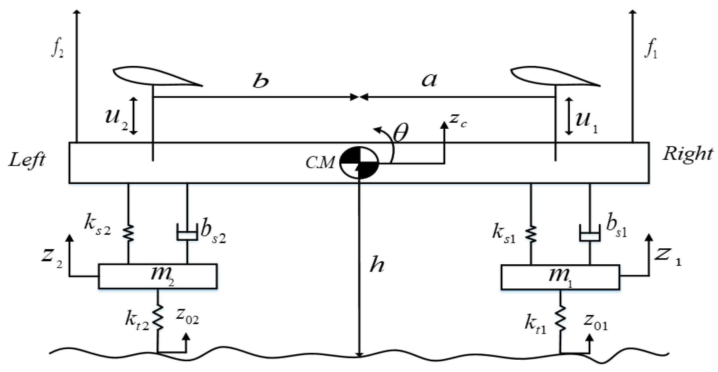
2. Problem Formulation of Four Degrees of Freedom (4-DOF) Half-Car Model

The present research considers a half-car model as a passive system (PS) with aerodynamic forces. The PS uses passive springs and dampers without any control actuator. Figure 1 shows the schematic diagram of the PS equipped with aerodynamic surfaces. The PS is installed between the sprung mass and unsprung mass. The aerodynamic actuators are installed at the right and left or front and rear position of the vehicle body, which provides the required downward control forces. The control inputs are applied to the sprung mass of the vehicle. In the figure, u 1 and u 2 are the control inputs while f 1 and f 2 are the disturbance forces acting on the vehicle body (sprung mass). z c is vertical displacement of sprung mass system. z 1 and z 2 are vertical displacements of unsprung mass system. z 01 and z 02 are road variations. θ is attitude (roll or pitch angle) and C.M is center of mass of the vehicle body. a and b denote the distances of the suspension from the C.M.
Table 1 lists the vehicle prominent parameters and their values considered in the present research. The vehicle model is used to track the desired attitude motion and to minimize the amplitude of oscillations occurring in vertical movement of the vehicle as well as in tyre deflection. The derived model addresses the roll and pitch motion of the vehicle body.
The equations describing vertical dynamics are written as:
m z ¨ c = f R + f 1 + f 2 + f L
where f R and f L are suspension forces acting on the sprung mass, and given in (2) and (3) respectively.
f R = k s 1 ( z 1 z c a θ ) + b s 1 ( z ˙ 1 z ˙ c a θ ˙ ) u 1
f L = k s 2 ( z 2 z c + b θ ) + b s 2 ( z ˙ 1 z ˙ c + b θ ˙ ) u 2
The disturbance forces f 1 and f 2 in (1) acting on the suspension mounting points of both sides have same magnitude and opposite direction. These forces acting on the body during roll motion and pitch motion can be written as in (4) and (5) respectively. In case of roll motion, the f1 = fr1 and f2 = fr2, and similarly in case of pitch motion, f1 = fp1, f2 = fp2.
f r 1 , 2 = | Fcos ( θ s ) mgsin ( θ s ) h a + b |
f p 1 , 2 = | ( F mgsin ( θ s ) ) h a + b |
where F is the centrifugal force during roll motion and is the inertial force during pitch motion acting on vehicle body as shown in Figure 2 and Figure 3, g is the gravitational force θ s is the road slope.
For the roll or pitch motion the equation is as:
I θ ¨ = ( f R + f 1 ) a ( f L + f 2 ) b
Equations of motion for the vertical motion of unsprung mass are given as:
m 1 z ¨ 1 = k t 1 ( z 1 z 01 ) f R 1
m 2 z ¨ 2 = k t 2 ( z 2 z 02 ) f L 1
where f L 1 and f R 1 are called suspension forces acting on unsprung mass are given in (9) and (10).
f L 1 = k s 2 ( z 2 z c + b θ ) b s 2 + ( z ˙ 2 z ˙ c + b θ ˙ )
f R 1 = k s 1 ( z 1 z c a θ ) b s 1 + ( z ˙ 1 z ˙ c a θ ˙ )

2.1. Desired Roll Angle

The schematic diagram to determine the desired roll angle of the vehicle body relative to the banked road angle is shown in Figure 2. The desired roll angle is computed as:
mgsin ( θ s + θ d ) = ma ca cos ( θ s + θ d )
a ca g = tan ( θ s + θ d )
a ca g = tan ( θ d ) + tan ( θ s ) 1 tan ( θ s ) tan ( θ d )
θ d = arctan [ a ca gtan ( θ s ) a ca tan ( θ s ) + g ]
where a ca is centrifugal acceleration and θ d is the desired roll angle of the car body.

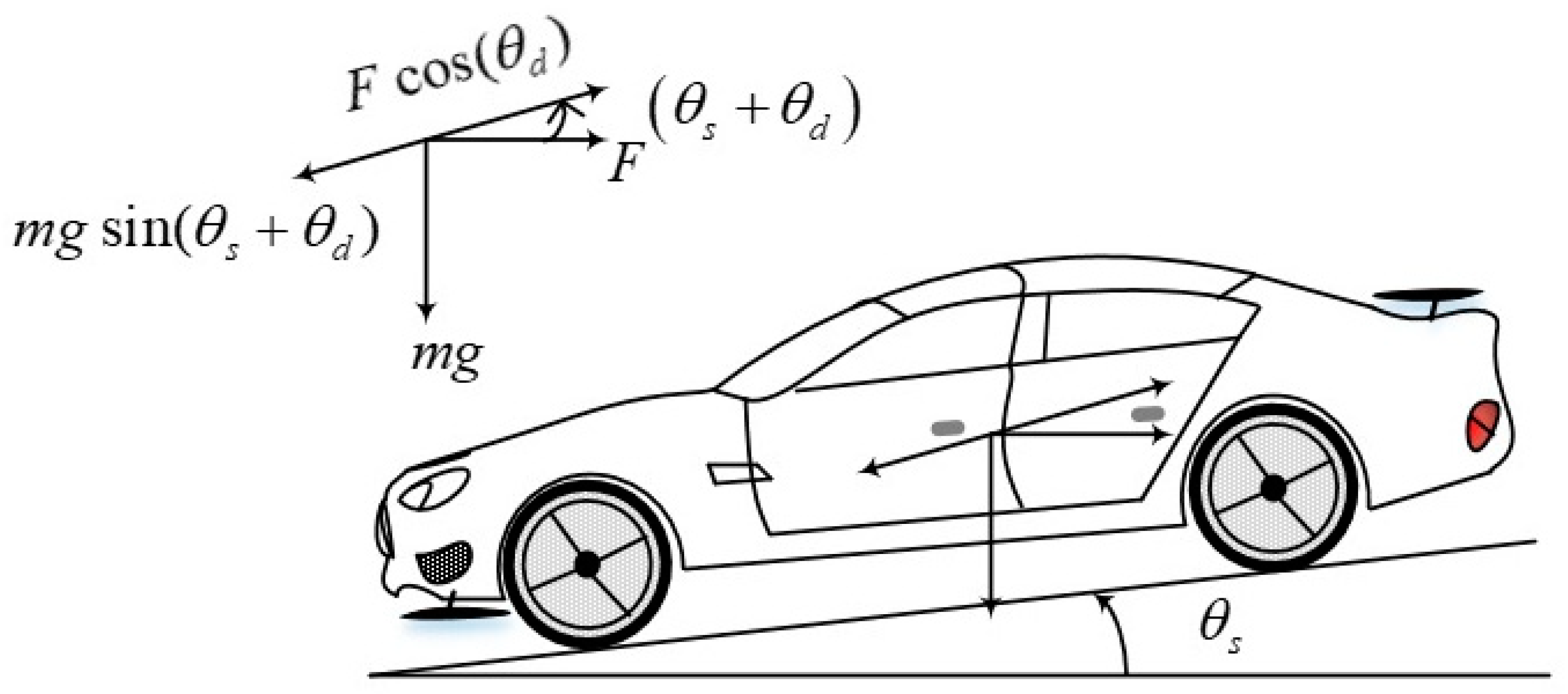
2.2. Desired Pitch Angle

Figure 3 shows the ideal pitch position in a horizontal plane. The desired pitch posture of a car body on the downhill will be parallel to the horizontal plane. The desired pitch angle can be computed as given in (15)–(17).
If θ s 0 , then:
mgsin ( θ s + θ d ) = ma ia cos ( θ d )
a ia g = sin ( θ s + θ d ) cos ( θ d ) = tan ( θ d ) cos ( θ s ) + sin ( θ s )
θ d = arctan ( a ia gcos ( θ s ) ) θ s
where a ia is inertial acceleration.
The desired roll angle in (14) and desired pitch angle in (17) are derived to eliminate the external lateral and longitudinal forces acting on the passengers. These forces are cancelled out such that the gravitational force counterbalances the lateral and longitudinal forces except for the normal forces.

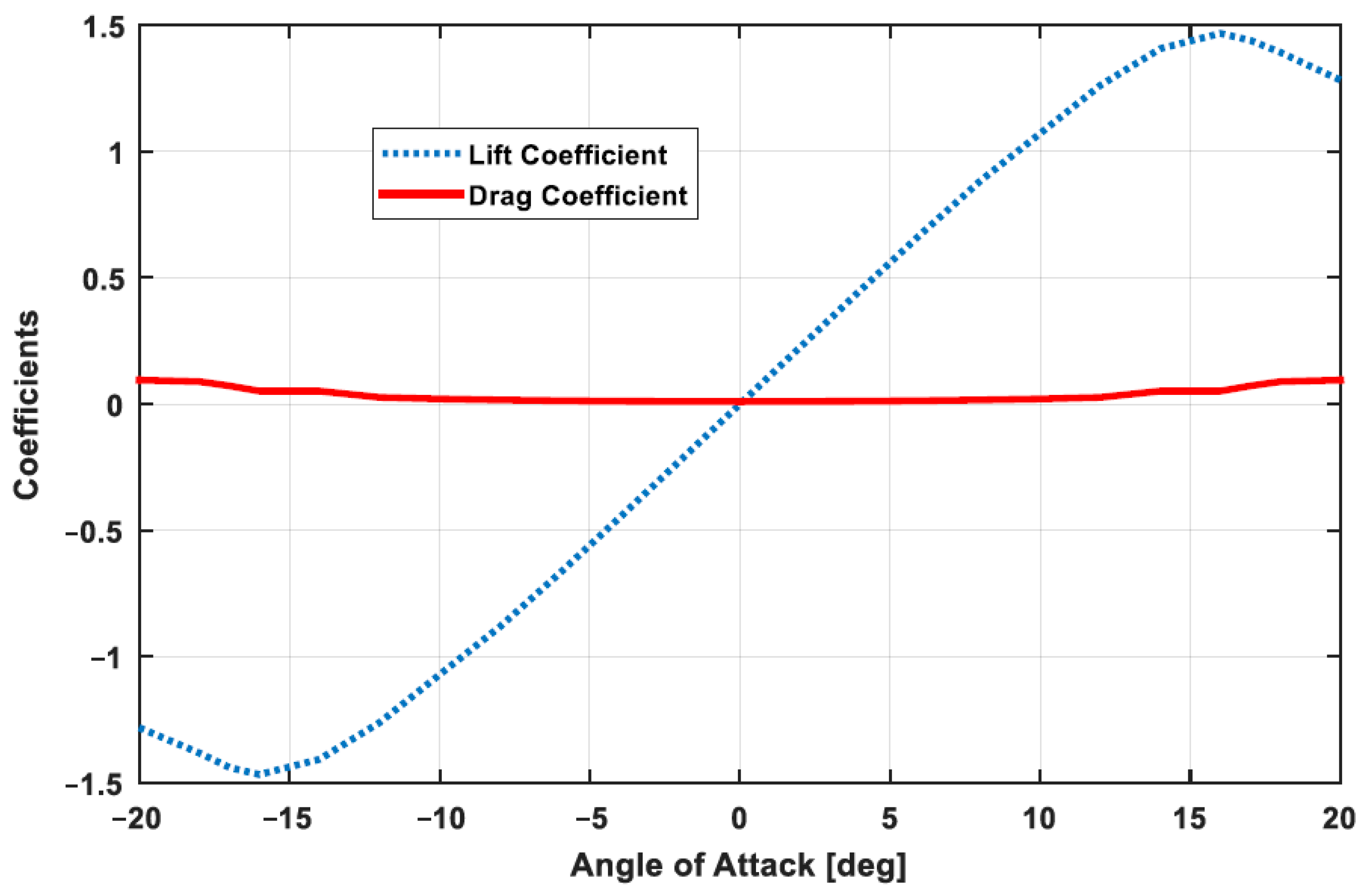
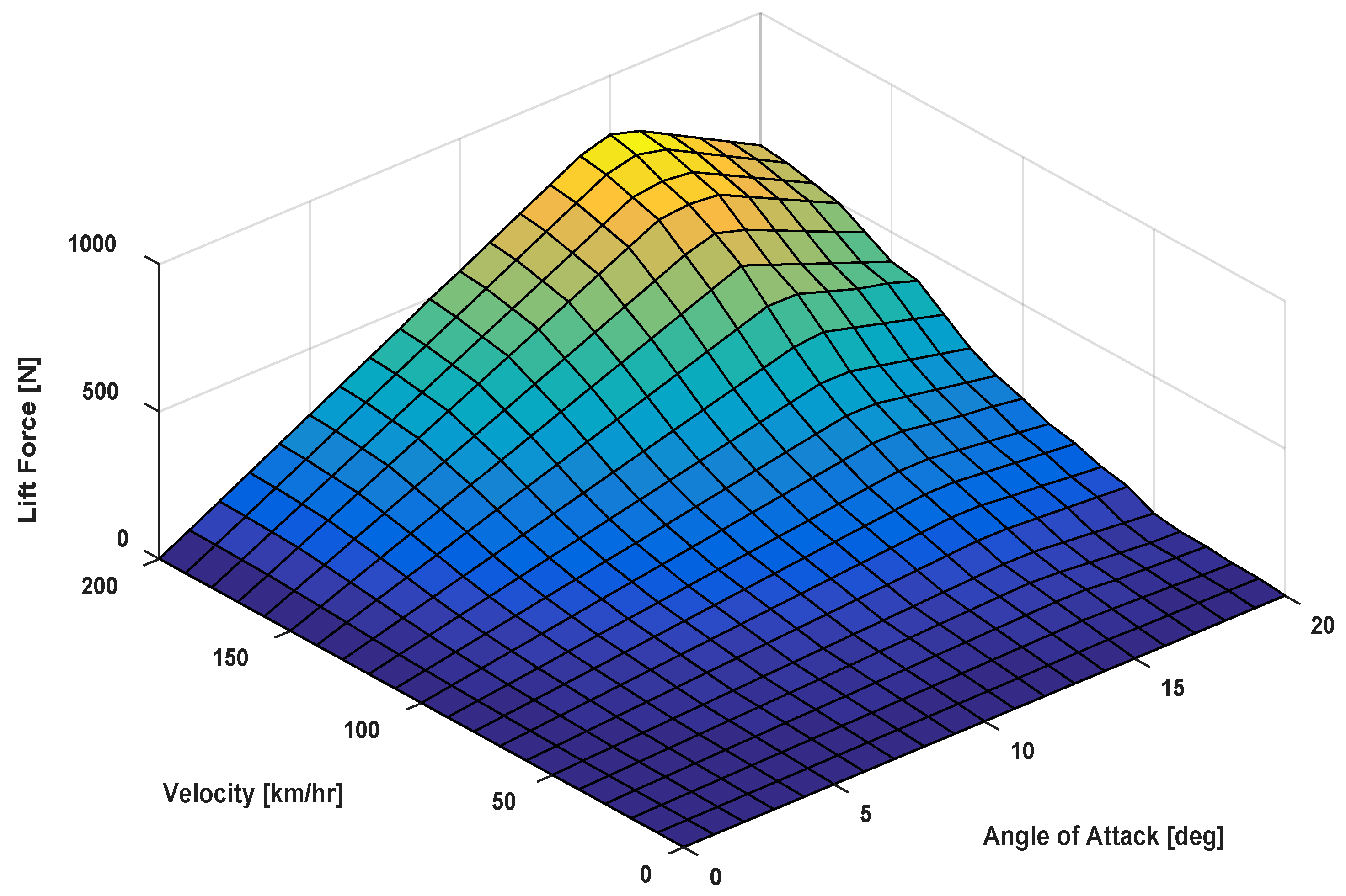
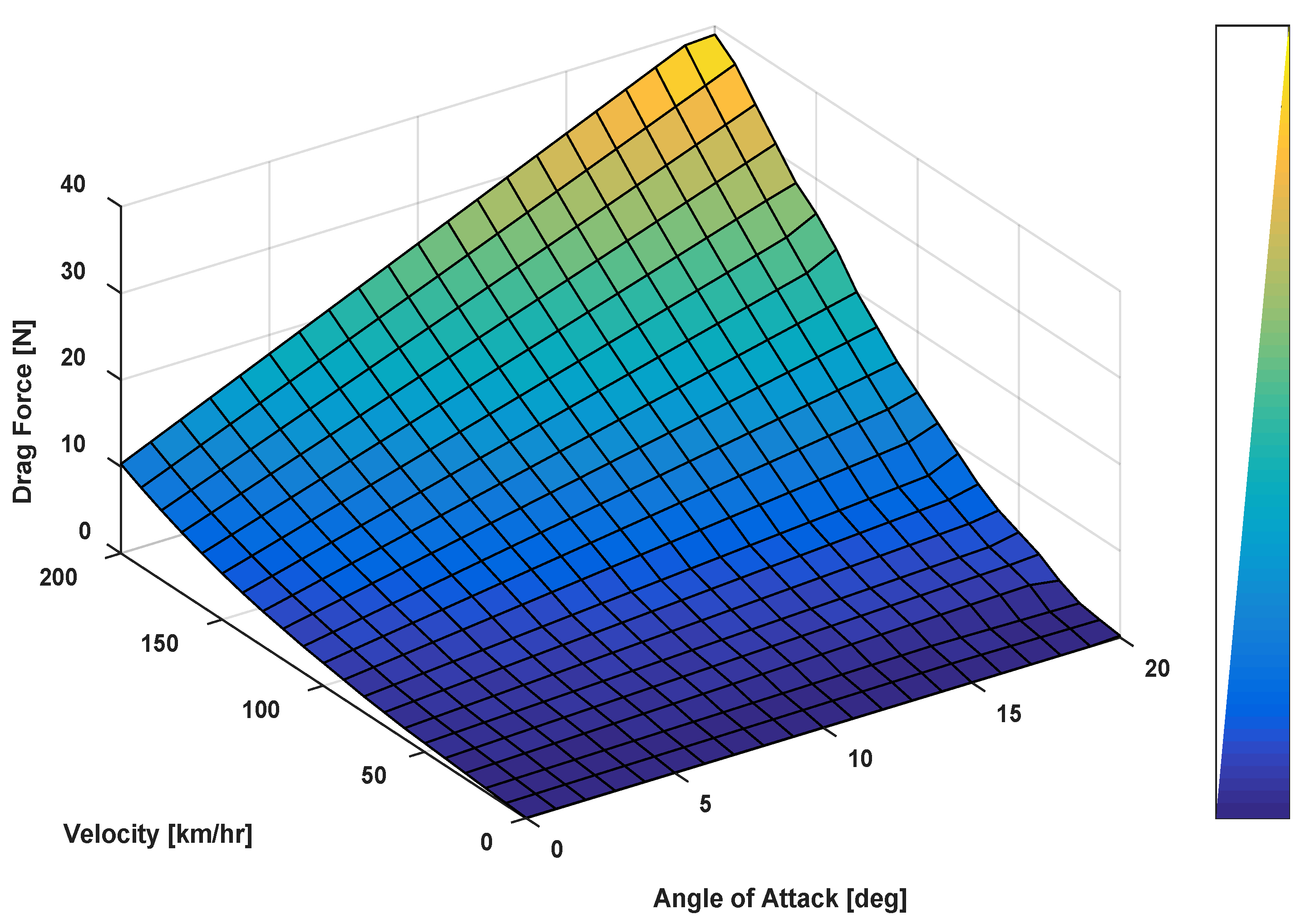
2.3. Aerodynamic Forces
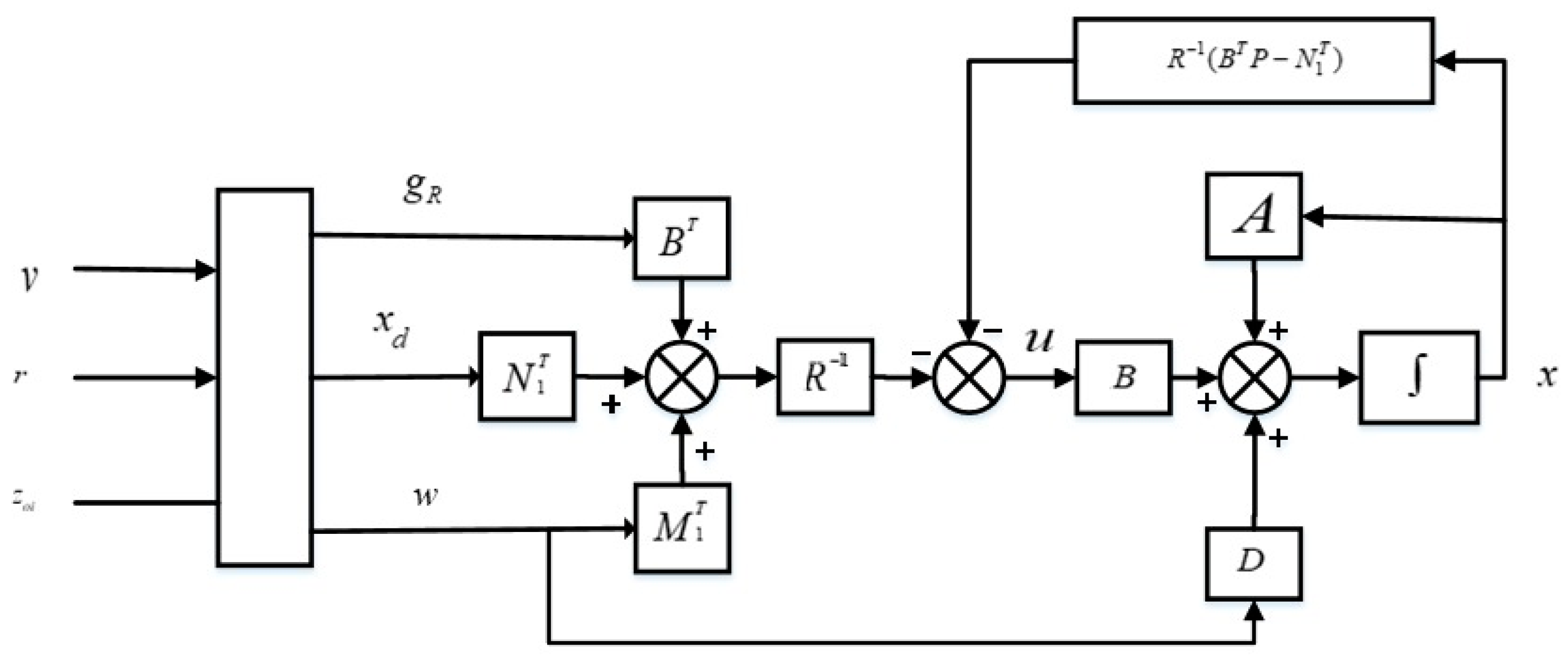
The primary objective of this work is to improve ride comfort and road-holding ability and to enhance vehicle-handling capability by using an active aerodynamic control system. The aerodynamic surfaces are subjected on the sprung mass, which generates the required forces to control the vertical motion of the vehicle body. The independent operation of aerodynamic surfaces provides different downward control forces. Therefore, the configuration of the aerodynamic surfaces can modify the distribution of downward forces. Such distribution has a powerful effect on ride comfort and road-holding capability. These forces can adjust the vertical load of the sprung mass system to affect the suspension deflection, acceleration of the vehicle body and tyre deflection. The suspension deflection affects rattle space which has a direct impact on the ride comfort. The tyre deflection is related to holding capability. In this work, a NACA0014 symmetrical airfoil is used to generate the downward control forces. The control forces generated by aerodynamic surfaces are given as:
F lift = 1 / 2 ρ v 2 SC lift ( α )
F drag = 1 / 2 ρ v 2 SC drag ( α )
where ρ is the air density, v is the vehicle speed, S is the airfoil surface, C lift and C drag are the lift and drag coefficients which depend on the angle of attack ( α ), shape of airfoil and roughness of the surface. The maximum lift force is generated at an angle of attack (AOA) α = 15 .
The constraint on the AOA is [ 15 , 15 ] to bound the lift coefficient. The drag coefficient is negligible as compared to the lift coefficient. The coefficients are plotted against the AOA in Figure 4, where it is evident that the lift coefficient is larger than the drag coefficient. Hence, maximum downward force can be generated by using aerodynamic surfaces. Figure 5 and Figure 6 illustrate the generated lift and drag forces of the airfoil, respectively. These results demonstrate the effect of AOA and vehicle speed on the generated lift and drag forces.
Figure 5 shows that a maximum of around 600   N lift force is generated corresponding to an AOA of 15 and 150 km/hr vehicle speed. Figure 6 illustrates the maximum drag force generated is 39.2 N at a vehicle speed of 200 km/hr and 20 AOA. Comparing Figure 5 and Figure 6, it is evident that the maximum lift force is much greater than the maximum drag force. Therefore, the opposite of lift force (i.e., downward force) is, relatively, a major factor in improving the performance of suspension system in terms of achieving better ride comfort, enhanced tyre grip on the road, and to enhance tracking performance for the desired attitude motion.

3. Control Strategy

A preview control strategy is proposed in the present research, which helps not only to track the desired roll angle and pitch angle of the vehicle body but also helps to improve the ride comfort and road-holding capability of the vehicle. The passive system is without controller. For both ASC and AACS, the control design procedure is very similar. The main difference lies in the application of control inputs. In AACS, the aerodynamic surfaces are installed on sprung mass, and therefore the control forces are directly applied to the sprung mass of the vehicle. However, in ASC, the actuator control inputs are applied between the sprung mass and unsprung mass system as discussed in [33]. The dynamic equations of motion are represented by a continuous time state-space vector equation as given in (20).
x ˙ = A x + B u + D w
where:
x = [ z c , z ˙ c , θ , θ ˙ , z 1 z 01 , z ˙ 1 , z 2 z 02 , z ˙ 2 , z 1 , z 2 ] T
w = [ Z ˙ o 1 , Z ˙ o 2 , f 1 , f 2 ] T
u = [ u 1 , u 2 ] T
The nonzero elements of matrix A n × n , B n × q and D n × p are given in Appendix A. where n is the number of states, q represents the number of inputs and p represents the number of disturbance inputs. The desired state vector containing the roll or pitch angle is given in (24).
x d = [ 0 , 0 , θ d , 0 , 0 , 0 , 0 , 0 , 0 , 0 ] T
The optimal tracking controller that minimizes the cost function consists of suspension acceleration, roll or pitch acceleration, suspension rattle space, the difference between the desired attitude angle and the actual angle, road-holding forces and control inputs. Therefore, the cost function is given by:
J = lim T 1 2 T 0 T [ ρ 1 x ˙ 2 2 + ρ 2 x ˙ 4 2 + ρ 3 ( x 1 + ax 3 x 9 ) 2 + ρ 3 ( x 1 bx 3 x 10 ) 2 + ρ 4 ( x d 3 x 3 ) 2 + ρ 5 x 5 2 + ρ 5 x 7 2 + ρ 6 u 1 2 + ρ 6 u 2 2 ] dt
The cost function in (25) can be rewritten in terms of matrices and the vectors which represent the control inputs, disturbance inputs and difference between the desired state and the system states.
J ( x , u , w ) = lim T 1 2 T 0 T [ ( x d x ) T Q ( x d x ) + 2 ( x d x ) T N 1 u + 2 ( x d x ) N 2 w + u T R u + 2 w T M 1 u + w T M 2 w ] dt
where Q n × n , N 1 n × q , N 2 n × p , M 1 p × q , M 2 p × p are positive definite matrices. R q × q is an identity matrix. It is assumed that the desired state vector in τ [ t ,   t + t p ] is known deterministically. If the pair ( A ,   B ) is stabilizable and ( A , Q ) are detectable, then the following tracking controller is obtained by minimizing the cost function given in (26).
u = R 1 [ ( B T P N 1 T ) x + N 1 T x d + M 1 T w + B T g R ]
Figure 7 shows the block diagram of the proposed control strategy. The control law consists of two parts, feedback part given by R 1 ( B T P N 1 T ) x and feedforward part expressed as ( N 1 T x d + M 1 T w + B T g R ). The feedback part is without the preview information of the predicted data corresponding to the desired states and disturbances. The feedforward part contains the preview information g R , which can be computed from the anticipated road disturbances and the desired angles.
The P in (27) is the solution of the algebraic Riccati equation (ARE) given in (29). The vector g R satisfies
g R = 0 t p e A c T τ [ ( PD n N n ) w ( τ ) ( Q n PBR 1 N 1 ) x d ( τ ) ] d τ
0 = Q n T + A n T P + PA n PBR 1 B T P
where:
A n = A + BR 1 N 1 T
Q n = Q N 1 R 1 N 1 T
D n = D BR 1 M 1 T
N n = N 2 N 1 R 1 M 1 T
A c = A n BR 1 B T P
where Matrix A c is closed loop asymptotically stable matrix. The closed-loop system equation can be written as:
x ˙ = A c x + D n w BR 1 N 1 T x d BR 1 B T g R

4. Results and Discussion

In this section, different cases for the vehicle roll and pitch motions are discussed based on a 4-DOF lateral and longitudinal half-car vehicle model. The performance of the vehicle equipped with an active aerodynamic surfaces is compared with the ASC and PS.
The simulations are carried out using MATLAB 2019b installed on Samsung core™ 5-6400 central processing unit (CPU) @ 2.70 GHz. The simulation results are performed for the roll and pitch motion of the vehicle travelling with a 150 km/hr speed. The results for tracking the desired roll angle and enhancing the ride comfort and road-holding capability are carried out for a circular maneuver and a lane-change maneuver. The simulations for the pitch motion are conducted out for a vehicle travelling on a flat road and for a downhill road. The results show that the proposed control strategy helps the vehicle to minimize the amplitude of oscillations occurring in vertical motion of the vehicle body and in tyre deflection to ensure a better ride comfort and holding capability.
The control strategy also helps the vehicle to successfully track the desired attitude motion by alleviating the external centrifugal and longitudinal forces acting on the vehicle body. Both AACS and ASC based strategies achieve the desired attitude motion. However, the AACS outperforms the ASC in terms of ride comfort and road-holding capability of the vehicle. In the case of a PS, the centrifugal and longitudinal forces cause a vehicle to tilt in the direction of the forces acting on the car body. The performance of AACS and ASC are compared based on the root mean square error (RMSE) method.

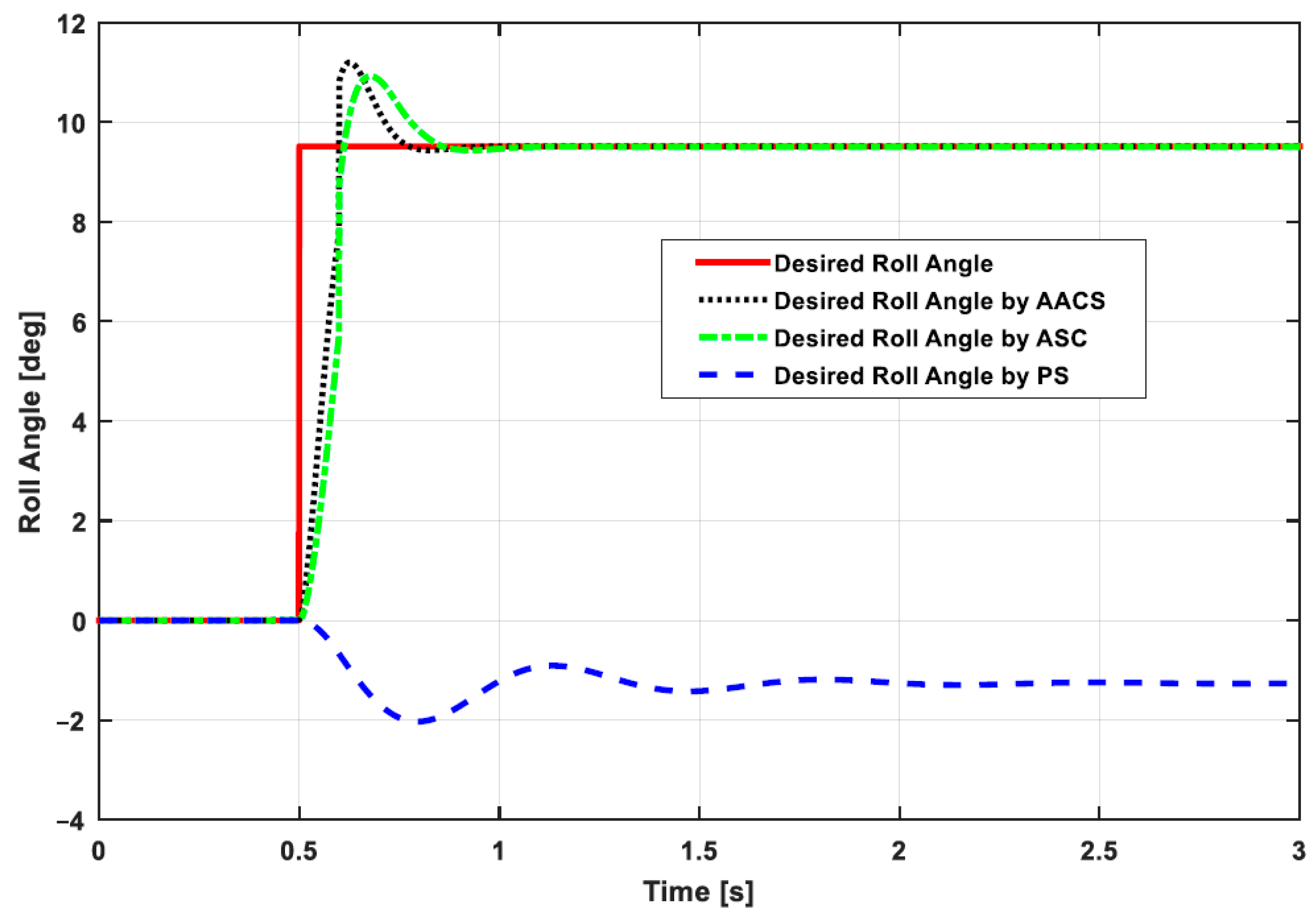
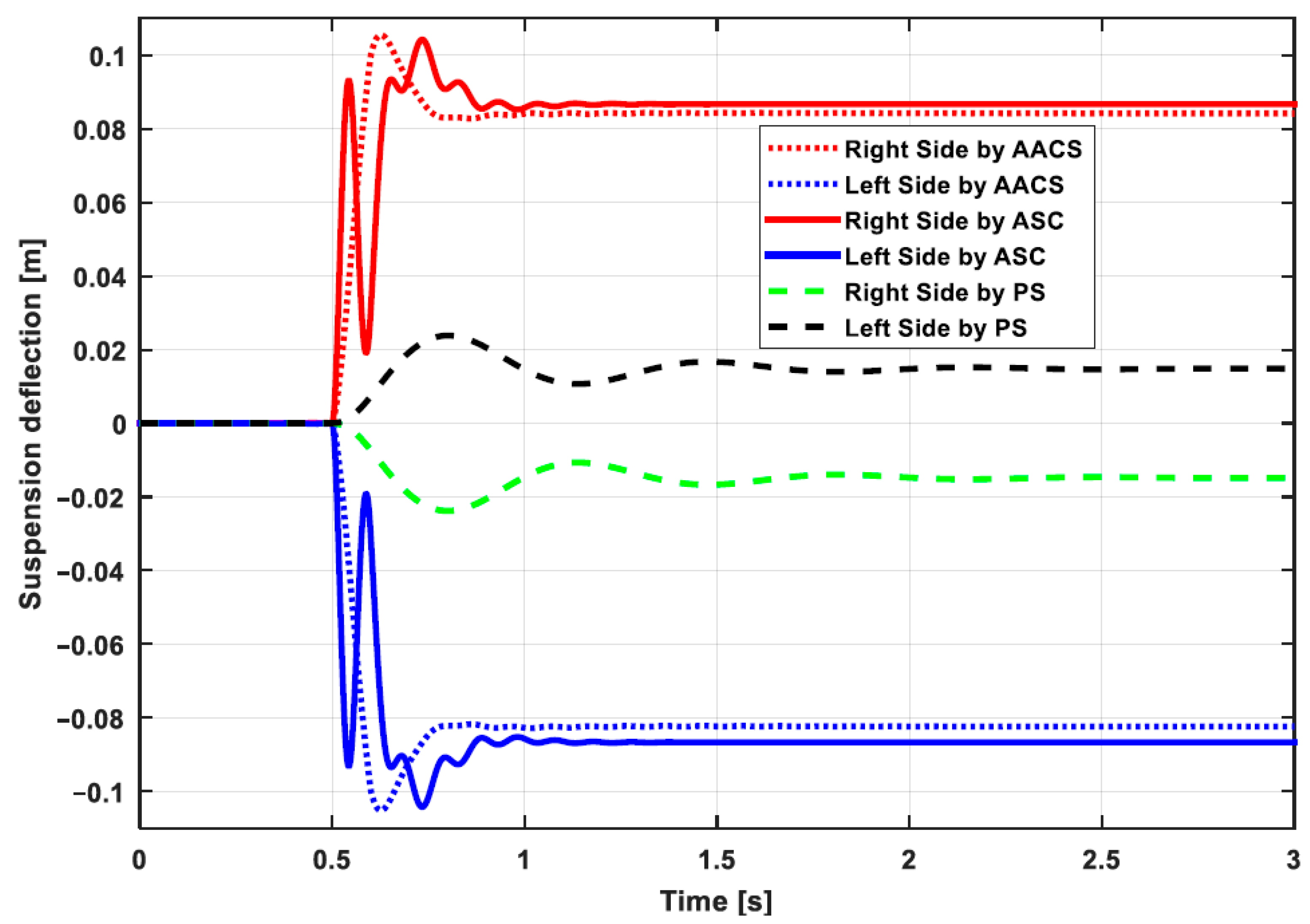
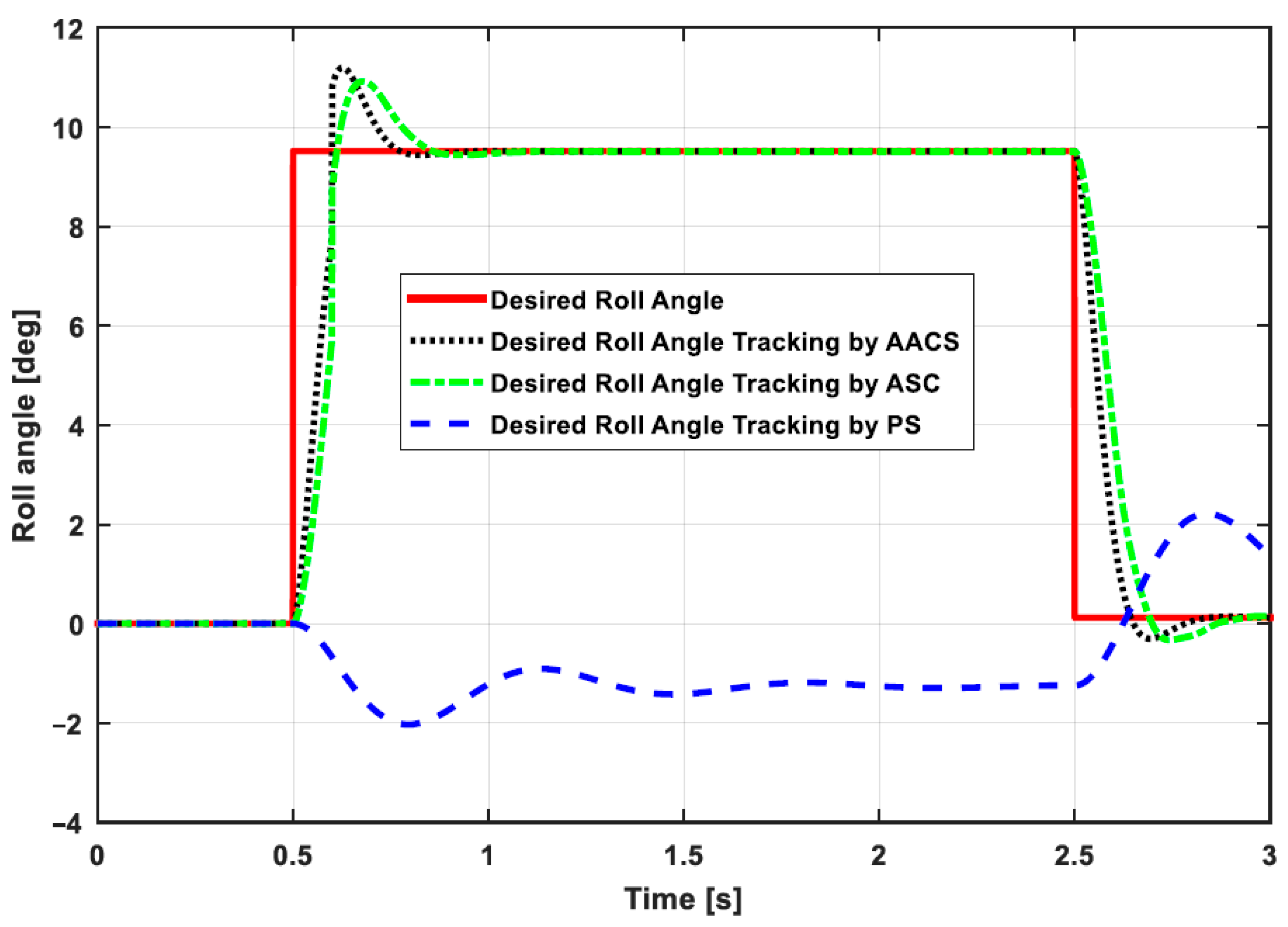
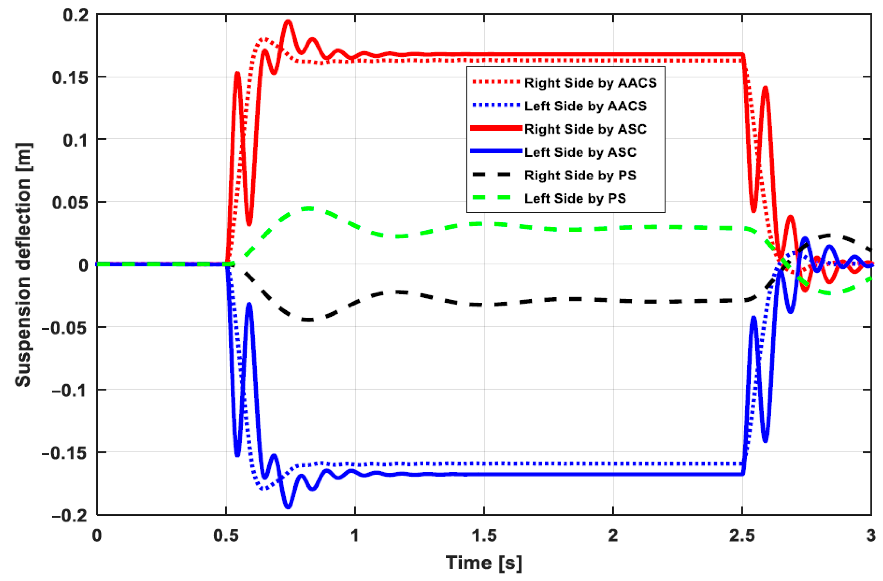
4.1. Desired Roll Angle Tracking

In the first case, performance of the vehicle travelling on a circular maneuver with 300   m radius and 3 of road slope is considered. Considering the road slope and centrifugal forces, the desired roll angle is determined as in (14). The performance of the active aerodynamic control strategy is compared with active ASC and PS. The simulation results for the desired roll angle tracking, vehicle sprung mass suspension, and tyre deflection are shown in Figure 8, Figure 9 and Figure 10, respectively. The results show that the proposed control strategy helps the vehicle body to track the desired roll angle, minimize the amplitude of oscillations in vertical motion of the vehicle body and to reduce the magnitude of oscillation in tyre deflection. The desired roll angle is achieved by tilting the car body in the opposite direction to cancel out the centrifugal forces acting on the car body.
Furthermore, it is clear from these results that a PS is directly affected by the centrifugal forces, since tilting the vehicle body in the direction of centrifugal forces causes instability to the vehicle. On the other hand, for AACS and ASC, the proposed controller helps the vehicle body to tilt inwards by cancelling out the centrifugal forces acting on the vehicle. Although both the ASC and AACS can accurately track the desired roll motion of the vehicle body, comparing the RMSE values revealed that AACS outperforms ASC. Compared to the ASC, AACS suppresses the amplitude of vibrations in vertical motion of the vehicle body and reduces the magnitude of oscillations in tyre deflection to increase its grip on the road. Table 2 shows the RMSE values for suspension deflection, tyre deflection and rolling motion. The RMSE value for suspension deflection offered by the proposed AACS is smaller compared to ASC. The RMSE value exhibited by the PS is smallest, but there is no perfect tracking by the PS. The RMSE value of AACS for the tyre deflection is smaller than the corresponding value in ASC, which implies that the former control strategy offers relatively higher tyre grip on the road. For the roll motion, the RMSE value of AACS is smaller than ASC and PS indicating that AACS demonstrates better ride comfort capability.
In the second case, the simulations for lane change maneuver are carried out for desired roll angle tracking, tyre and suspension deflection. The simulations are performed for an AACS and ASC and a PS. The results shown in Figure 11 demonstrate that the proposed control strategy cancels out the centrifugal forces acting on the vehicle body in efforts to tilt the car body inwards to track the desired roll motion successfully. The PS is badly affected by centrifugal forces acting on the car body, which try to tilt the vehicle body in the direction of lateral forces.
The simulation results show that AACS and the ASC successfully track the desired roll motion for vehicle travelling in a lane change maneuver. The RMSE values given in Table 3 show that AACS demonstrates smaller value in case of roll motion when compared with ASC thus achieving better tracking of roll motion. Figure 12 shows the results for the suspension deflection, where it can be seen that AACS minimizes the amplitude of vibrations in vertical motion of the vehicle body. ASC shows more oscillations as compared to AACS which implies that AACS outperforms ASC to achieve better ride comfort. The simulation results for the tyre deflection are shown in Figure 13, which indicates that AACS minimizes the amplitude of vibrations in tyre deflection as compared to ASC. The RMSE value of AACS is less than that of ASC demonstrating that the tyres will have more relative grip on the road in the case of AACS. PS exhibits smaller RMSE values for suspension deflection as well as tyre deflection, but has a high RMSE value for rolling indicating instability in the vehicle during cornering.

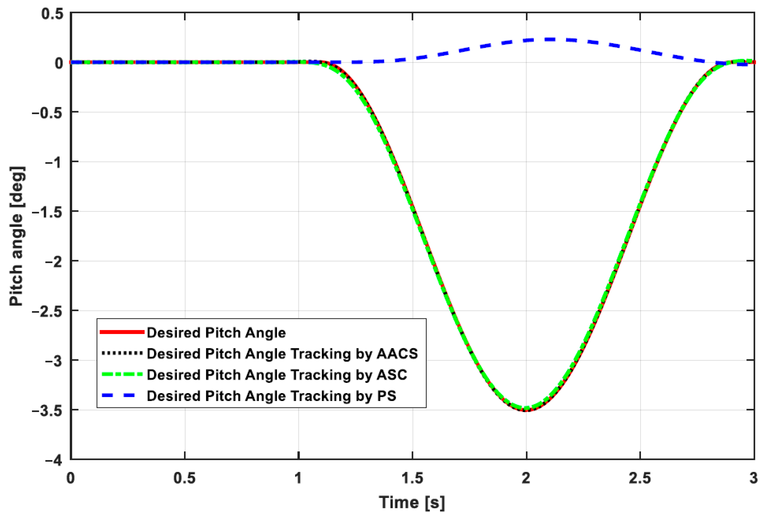
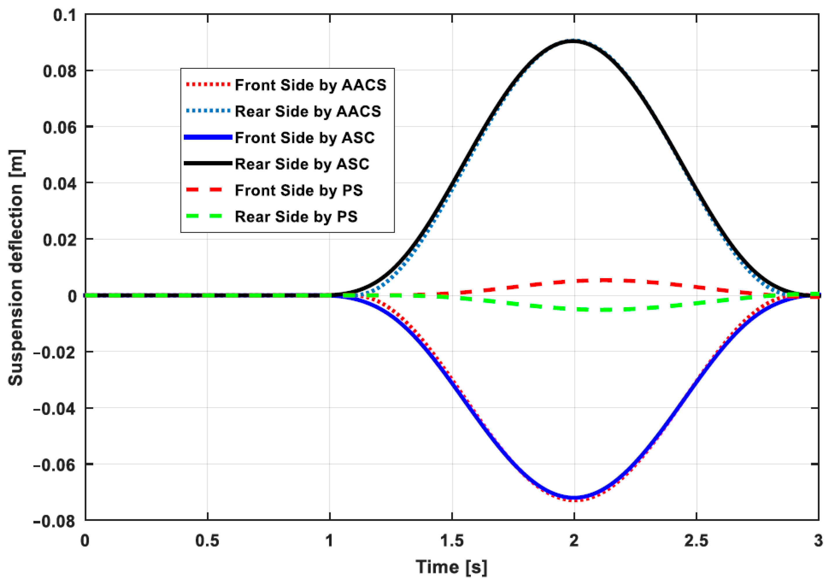
4.2. Desired Pitch Angle Tracking

In this section, the simulations are performed for two scenarios; a flat road with θ s = 0 and a downhill road with θ s = 5 . When a vehicle is travelling on a straight maneuver, the acceleration produces inertial forces to affect the ride comfort and road-holding capability. The vehicle forward pitch is the most appropriate solution to counter the inertial effects generated while accelerating the vehicle. The desired pitch angle is considered to be zero so as to let the passenger feel comfortable. The accelerating forces applied during each pitch motion are shown in Figure 14. Table 4 includes the RMSE values for the vehicle travelling on a flat road. The simulation results for desired pitch angle tracking in this case are shown in Figure 15. The results indicate that the AACS shows excellent performance for desired pitch motion tracking. The tracking by the ASC is also satisfactory, however the response is slow compared to AACS. The RMSE value of AACS for desired pitch tracking is smaller than the corresponding value in ACS.
Figure 16 shows the performance of AACS, ASC and PS for suspension deflection of a vehicle. The RMSE value of AACS for the suspension deflection is less than the RSME value of ASC indicating better ride comfort. The PS is unable to obtain the required suspension forces to track the desired pitch motion. The results also show that the road-holding capability of the vehicle is improved by using AACS. The proposed control strategy successfully minimizes the amplitude of vibrations occurring in tyre deflection to increase the grip of the tyres on the road. Hence, AACS gives better tracking performance than ASC. The comparative results for tyre deflection in case of AACS, ASC and PS are shown in Figure 17. The results show that the oscillations in tyre deflection are reduced in case of AACS. In contrast, in case of the ASC, there are still oscillations that affect the ride comfort and road-holding capability of the vehicle. The RMSE values of AACS and ASC for the tyre deflection are given in Table 4, which indicates that smaller RMSE value of AACS demonstrates more tyre grip on the road and thus enhanced road-holding capability. The tyre deflection for the PS is minimum; however, it is unable to track the desired pitch motion thus severely affecting the vehicle-handling capability. The desired pitch angle for a vehicle travelling with constant velocity on the downhill is zero because the pitch angle should be parallel to the horizontal plane. The vehicle’s backwards pitch is the most appropriate solution to counter the inertial forces generated while accelerating a vehicle on a downslope road.
The simulation results of tracking the desired pitch motion on a downhill road are shown in Figure 18. The PS is unable to achieve the desired pitch angle while moving with a constant speed on a steep downhill. In contrast, AACS and the ASC help the car body to keep the pitch angle parallel to the horizontal plane. The AACS supports the vehicle to track the desired pitch angle in 0.3 s, while the ASC tracks the desired pitch angle in 0.5 s. The RMSE value of 2.14 in the case of AACS is less than the corresponding value (2.569) for ASC. Hence, better tracking performance is achieved by the AACS due to less rise time as well as less settling time as shown in Figure 18. The simulation results for suspension and tyre deflection on the downhill road are shown in Figure 19 and Figure 20 respectively. The RMSE values for the downhill road are shown in Table 5. Figure 19 shows that the suspension deflection for AACS exhibits relatively less oscillations compared to that in ASC. This phenomenon is particularly evident during transient phase before a time span of 0.5 s as demonstrated in Figure 19. AACS gives RMSE value of 5.06 for suspension deflection, which is less than the RMSE value obtained in the case of ASC. The minimum oscillations and less RMSE value demonstrated by AACS conclude that the ride comfort is improved in this control strategy.
The simulation results for the tyre deflection are shown in Figure 20. Here, the oscillations in tyre deflection are reduced by AACS. In the case of ASC, the oscillations in the tyre deflection reduce the tyre grip on the road which ultimately weakens the road-holding capability. AACS gives the 0.7868 RMSE value for tyre deflection, which is less than the corresponding value of 0.8654 obtained by ASC. Hence, the road-holding capability of the vehicle is enhanced in the case of AACS. The results for the PS are worst in terms of tracking the desired pitch motion. This is primarily due to the fact that in PS, center of mass of the vehicle is shifted towards the front, which is why the pitch angle of the car body is less than the slope of the road.

5. Conclusions

In this paper, the forces generated by aerodynamic surfaces are applied to improve the ride comfort, road-holding ability, vehicle-handling capability and desired roll and pitch motion tracking of a vehicle. An optimal predictive control strategy is proposed to track the desired attitude motion and to suppress the amplitude of vibrations in the sprung mass system as well as in tyre deflection so as to achieve the desired objectives. The performance of AACS is compared with an ASC and PS. The simulations are carried out for circular and lane-change maneuvers to track the desired roll angle while for the pitch angle tracking, simulations are performed for flat and downhill roads. The performance of the control strategies are compared based on RMSE values. The results show that the proposed AACS outperforms the other two systems. It is demonstrated that the aerodynamic forces tilt the car body inwards during cornering and successfully suppress vibrations to improve the road-holding capability and ride comfort.

Author Contributions

E.A. surveyed the background of this research, presented the problem formulation and designed the control strategy for the addressed problem. J.I. helped in validation of the research work and in reviewing the manuscript, M.A.K. and W.L. assisted in technical writing and MATLAB simulations, I.Y. conceptualized the research idea and supervised the research. All authors have read and agreed to the published version of the manuscript.

Funding

This study was supported by the BK-21 Plus Program funded by the Ministry of Education and National Research Foundation of South Korea (NRF).

Conflicts of Interest

The authors declare no conflict of interest.

Appendix A

a 11 = 1 , a 21 = k s 1 + k s 2 M , a 22 = b s 1 + b s 2 M , a 23 = ak s 1 + bk s 2 M , a 24 = b s 1 a b s 2 b M , a 26 = b s 1 M , a 28 = b s 2 M , a 29 = k s 1 M , a 210 = k s 2 M , a 34 = 1 , a 41 = ( k s 1 a k s 2 b ) I , a 42 = b s 1 a b s 2 b I , a 43 = k s 1 a 2 + k s 2 b 2 I , a 44 = b s 1 a 2 + b s 2 b 2 I , a 46 = b s 1 a I , a 48 = b s 2 b I , a 49 = k s 1 a I , a 410 = k s 2 b M , a 57 = 1 , a 61 = k s 1 m 1 , a 62 = b s 1 m 1 , a 63 = ak s 1 m 1 , a 64 = b s 1 a m 1 , a 65 = k t 1 m 1 , a 66 = b s 2 M , a 69 = k s 1 m 1 , a 78 = 1 , a 81 = k s 2 / m 2 , a 82 = b s 2 m 2 , a 83 = k s 2 b m 2 , a 84 = b s 2 b m 2 , a 87 = k t 2 m 2 , a 88 = b s 2 m 2 , a 810 = k s 2 m 2 , a 96 = 1 , a 108 = 1 .
The elements of matrix A , B and D are given as:
A = [ a 11 a 12 a 13 a 14 a 15 a 16 a 17 a 18 a 19 a 110 a 21 a 22 a 23 a 24 a 25 a 26 a 27 a 28 a 29 a 210 a 31 a 32 a 33 a 34 a 35 a 36 a 37 a 38 a 39 a 310 a 41 a 42 a 43 a 44 a 45 a 46 a 47 a 48 a 49 a 410 a 51 a 52 a 53 a 54 a 55 a 56 a 57 a 58 a 59 a 510 a 61 a 62 a 63 a 64 a 65 a 66 a 67 a 68 a 69 a 610 a 71 a 72 a 73 a 74 a 75 a 76 a 77 a 78 a 79 a 710 a 81 a 82 a 83 a 84 a 85 a 86 a 87 a 88 a 89 a 810 a 91 a 92 a 93 a 94 a 95 a 96 a 97 a 98 a 99 a 910 a 101 a 102 a 103 a 104 a 105 a 106 a 107 a 108 a 109 a 1010 ]
B = [ 0 0 1 M 1 M 0 0 a I b I 0 0 0 0 0 0 0 0 0 0 0 0 ] ,   D = [ 0 0 0 0 0 0 1 M 1 M 0 0 0 0 0 0 a I b I 1 0 0 0 0 0 0 0 0 1 0 0 0 0 0 0 0 0 0 0 0 0 0 0 ]
The elements of matrix Q can be written as:
q ij = ρ 1 a 2 i a 2 j + ρ 2 a 4 i a 4 j
Especially,
q 11 = ρ 1 a 21 a 21 + ρ 2 a 41 a 41 + 2 ρ 3 ,   q 13 = ρ 1 a 21 a 23 + ρ 2 a 41 a 43 + ρ 3 ( a b ) q 19 = ρ 1 a 21 a 29 + ρ 2 a 41 a 49 ρ 3 ,   q 110 = ρ 1 a 21 a 210 + ρ 2 a 41 a 410 ρ 3 q 33 = ρ 1 a 23 a 23 + ρ 2 a 43 a 43 + ρ 3 ( a 2 + b 2 ) + ρ 4 ,   q 39 = ρ 1 a 23 a 29 + ρ 2 a 43 a 49 ρ 3 a q 310 = ρ 1 a 23 a 210 + ρ 2 a 43 a 410 ρ 3 b ,   q 55 = ρ 1 a 25 a 25 + ρ 2 a 45 a 45 + ρ 5 q 57 = ρ 1 a 25 a 27 + ρ 2 a 45 a 47 + ρ 5 ,   q 77 = ρ 1 a 27 a 27 + ρ 2 a 47 a 47 + ρ 5 q 99 = ρ 1 a 29 a 29 + ρ 2 a 49 a 49 + ρ 3 ,   q 1010 = ρ 1 a 210 a 210 + ρ 2 a 410 a 410 + ρ 3
The elements of matrix N 1 can be written as:
n 1 ij = ρ 1 a 2 i b 2 j + ρ 2 a 4 i b 4 j
The elements of matrix N 2 are given as:
n 2 ij = ρ 1 a 2 i d 2 j + ρ 2 a 4 i d 4 j
The elements of matrix M 1
m 1 ij = ρ 1 d 2 i b 2 j + ρ 2 d 4 i b 4 j
The elements for matrix M 2 are give as:
m 2 ij = ρ 1 d 2 i d 2 j + ρ 2 d 4 i d 4 j
where a ij represents the elements of A matrix, b ij represents the elements of B and d ij represents the elements of matrix D .

References

  1. Youn, I.; Tchamna, R.; Lee, S.; Uddin, N.; Lyu, S.; Tomizuka, M. Preview suspension control for a full tracked vehicle. Int. J. Automot. Technol. 2014, 15, 399–410. [Google Scholar] [CrossRef]
  2. Tchamna, R.; Lee, M.; Youn, I. Attitude control of full vehicle using variable stiffness suspension control. Optim. Control Appl. Methods 2015, 36, 936–952. [Google Scholar] [CrossRef]
  3. Naranjo, J.E.; Serradilla, F.; Nashashibi, F. Speed Control Optimization for Autonomous Vehicles with Metaheuristics. Electronics 2020, 9, 551. [Google Scholar] [CrossRef] [Green Version]
  4. Iqbal, U.; Samad, A.; Nissa, Z.; Iqbal, J. Embedded control system for AUTAREP-A novel autonomous articulated robotic educational platform. Tehnički Vjesnik-Technical Gazette 2014, 21, 1255–1261. [Google Scholar]
  5. Iqbal, J.; Ullah, M.; Khan, S.G.; Khelifa, B.; Ćuković, S. Nonlinear control systems-A brief overview of historical and recent advances. Nonlinear Eng. 2017, 6, 301–312. [Google Scholar] [CrossRef]
  6. Iqbal, J. Modern control laws for an articulated robotic arm. Eng. Technol. Appl. Sci. Res. 2019, 9, 4057–4061. [Google Scholar]
  7. Doniselli, C.; Mastinu, G.; Gobbi, M. Aerodynamic effects on ride comfort and road holding of automobiles. Veh. Syst. Dyn. 1996, 25, 99–125. [Google Scholar] [CrossRef]
  8. Qin, Y.; He, C.; Shao, X.; Du, H.; Xiang, C.; Dong, M. Vibration mitigation for in-wheel switched reluctance motor driven electric vehicle with dynamic vibration absorbing structures. J. Sound Vib. 2018, 419, 249–267. [Google Scholar] [CrossRef]
  9. Nie, S.; Zhuang, Y.; Liu, W.; Chen, F. A semi-active suspension control algorithm for vehicle comprehensive vertical dynamics performance. Veh. Syst. Dyn. 2017, 55, 1099–1122. [Google Scholar] [CrossRef]
  10. Aleksander, H.; Youn, I. Optimal semi-active suspension with preview based on a quarter car model. In Proceedings of the American Control Conference, Boston, MA, USA, 26–28 June 1991; pp. 433–438. [Google Scholar]
  11. Aleksander, H.; Youn, I.; Chen, H.H. Control of suspensions for vehicles with flexible bodies—Part I: Active suspensions. J. Dyn. Syst. Meas. Control 1996, 118, 508–517. [Google Scholar]
  12. Bouazara, M.; Richard, M.J. An optimization method designed to improve 3-D vehicle comfort and road holding capability through the use of active and semi-active suspensions. Eur. J. Mech. A/Solids 2001, 20, 509–520. [Google Scholar] [CrossRef]
  13. Jia, G.; Li, L.; Cao, D. Model-based estimation for vehicle dynamics states at the limit handling. J. Dyn. Syst. Meas. Control 2015, 137, 1–8. [Google Scholar] [CrossRef]
  14. Saglam, F.; Unlusoy, Y.S. Adaptive ride comfort and attitude control of vehicles equipped with active hydro-pneumatic suspension. Int. J. Veh. Des. 2016, 71, 31–51. [Google Scholar] [CrossRef]
  15. Basrah, M.S.; Siampis, E.; Velenis, E.; Cao, D.; Longo, S. Wheel slip control with torque blending using linear and nonlinear model predictive control. Veh. Syst. Dyn. 2017, 55, 1665–1685. [Google Scholar] [CrossRef] [Green Version]
  16. Zhang, J.; Li, X.; Liu, D. Mine car suspension parameter optimisation based on improved particle swarm optimisation and approximation model. Int. J. Veh. Des. 2019, 80, 23–40. [Google Scholar] [CrossRef]
  17. Yang, S.; Baddour, N.; Li, C. Design and evaluation of a passive inertial mass device for car suspension system. Int. J. Veh. Des. 2019, 80, 41–58. [Google Scholar] [CrossRef]
  18. Boufadene, M.; Belkheiri, M.; Rabhi, A.; Hajjaji, A.E. Vehicle longitudinal force estimation using adaptive neural network nonlinear observer. Int. J. Veh. Des. 2019, 79, 205–220. [Google Scholar] [CrossRef]
  19. Savkoor, A.R.; Chou, C. Application of aerodynamic actuators to improve vehicle handling. Veh. Syst. Dyn. 1999, 32, 345–374. [Google Scholar]
  20. Savkoor, A. Aerodynamic Vehicle Ride Control with Active Spoilers. Available online: https://ci.nii.ac.jp/naid/10007202754/#cit (accessed on 2 July 2020).
  21. Savkoor, A.; Manders, S.; Riva, P. Design of actively controlled aerodynamic devices for reducing pitch and heave of truck cabins. JSAE Rev. 2001, 22, 421–434. [Google Scholar] [CrossRef]
  22. Meijaard, J.; Savkoor, A.; Lodewijks, G. Potential for Vehicle Ride Improvement using both Suspension and Aerodynamic Actuators. In Proceedings of the IEEE International Symposium on Industrial Electronics, Dubrovnik, Croatia, 10–14 July 1995; pp. 385–390. [Google Scholar]
  23. Corno, M.; Bottelli, S.; Panzani, G.; Tanelli, M.; Spelta, C.; Savaresi, S.M. Improving high speed road-holding using actively controlled aerodynamic surfaces. In Proceedings of the European Control Conference, Zurich, Switzerland, 17–19 July 2013; pp. 1493–1498. [Google Scholar]
  24. Corno, M.; Bottelli, S.; Panzani, G.; Spelta, C.; Tanelli, M.; Savaresi, S.M. Performance assessment of active aerodynamic surfaces for comfort and handling optimization in sport cars. IEEE Trans. Control Syst. Technol. 2015, 24, 189–199. [Google Scholar] [CrossRef]
  25. Wu, Y.; Chen, Z. Improving Road Holding and Ride Comfort of Vehicle Using Dual Active Aerodynamic Surfaces. In Proceedings of the 2nd International Conference on Robotics and Automation Sciences, Wuhan, China, 23–25 June 2018; pp. 1–5. [Google Scholar]
  26. Hosseinian Ahangarnejad, A.; Melzi, S. Numerical analysis of the influence of an actively controlled spoiler on the handling of a sports car. J. Vib. Control 2018, 24, 5437–5448. [Google Scholar] [CrossRef]
  27. Shahein, A.H.; Ata, A.A.; Haraz, E.H.; El-Souhily, B.M. Vibration suppression of terrains irregularities using active aerodynamic surface for half-car model sport vehicles. J. Vib. Control 2020. [Google Scholar] [CrossRef]
  28. Gáspár, P.; Szaszi, I.; Bokor, J. Reconfigurable control structure to prevent the rollover of heavy vehicles. Control Eng. Pract. 2005, 13, 699–711. [Google Scholar] [CrossRef]
  29. Goodall, R. Tilting trains and beyond-the future for active railway suspensions. Part 1: Improving passenger comfort. Comput. Control Eng. J. 1999, 10, 153–160. [Google Scholar] [CrossRef]
  30. Wang, J.; Shen, S. Integrated vehicle ride and roll control via active suspensions. Veh. Syst. Dyn. 2008, 46, 495–508. [Google Scholar] [CrossRef]
  31. Wu, Z.; Liu, Y.; Pan, G. A smart car control model for brake comfort based on car following. IEEE Trans. Intell. Transp. Syst. 2008, 10, 42–46. [Google Scholar]
  32. Tchamna, R.; Youn, E.; Youn, I. Combined control effects of brake and active suspension control on the global safety of a full-car nonlinear model. Veh. Syst. Dyn. 2014, 52, 69–91. [Google Scholar] [CrossRef]
  33. Youn, I.; Wu, L.; Youn, E.; Tomizuka, M. Attitude motion control of the active suspension system with tracking controller. Int. J. Automot. Technol. 2015, 16, 593–601. [Google Scholar] [CrossRef]
  34. Youn, I.; Youn, E.; Khan, M.A.; Wu, L.; Tomizuka, M. Combined effect of electronic stability control and active tilting control based on full-car nonlinear model. In Proceedings of the Dynamics of Vehicles on Roads and Tracks: Proceedings of the 24th Symposium of the International Association for Vehicle System Dynamics, Graz, Austria, 17–21 August 2015; p. 345. [Google Scholar]
  35. Liang, W.; Khan, M.A.; Youn, E.; Youn, I.; Tomizuka, M. Attitude motion control of vehicle including the active passenger seat system. Int. J. Veh. Des. 2018, 78, 131–160. [Google Scholar] [CrossRef]
  36. Ahmad, E.; Song, Y.; Khan, M.A.; Youn, I. Attitude Motion Control of a Half car Model with Tracking Controller Using Aerodynamic Surfaces. In Proceedings of the International Automatic Control Conference 2019, Keelung, Taiwan, 13–16 November 2019; pp. 1–6. [Google Scholar]
  37. Savaresi, S.M.; Poussot-Vassal, C.; Spelta, C.; Sename, O.; Dugard, L. Semi-Active Suspension Control Design for Vehicles; Elsevier: London, UK, 2010. [Google Scholar]
Figure 1. Schematic diagram of half-car model with passive suspension equipped with aerodynamic surfaces.
Electronics 09 01463 g001
Figure 2. Desired roll angle of vehicle traveling on circular maneuver.
Electronics 09 01463 g002
Figure 3. Ideal pitch angle of vehicle traveling on a downhill road.
Electronics 09 01463 g003
Figure 4. Lift and drag coefficients as a function of angle of attack.
Electronics 09 01463 g004
Figure 5. Lift force generated by the aerodynamic surface.
Electronics 09 01463 g005
Figure 6. Drag force generated by the aerodynamic surface.
Electronics 09 01463 g006
Figure 7. Block diagram for the proposed control strategy.
Electronics 09 01463 g007
Figure 8. Roll angle of vehicle body traveling on circular maneuver with slope θ s = 3 and radius of curvature r = 300   m .
Electronics 09 01463 g008
Figure 9. Suspension deflection of vehicle travelling on circular maneuver with slope θ s = 3 and radius of curvature r = 300   m .
Electronics 09 01463 g009
Figure 10. Tyre deflection of vehicle travelling on circular maneuver with slope θ s = 3 and radius of curvature r = 300   m .
Electronics 09 01463 g010
Figure 11. Roll angle of the vehicle body travelling in lane change maneuver with slope θ s = 3 and radius of curvature r = 180   m .
Electronics 09 01463 g011
Figure 12. Suspension deflection of vehicle traveling on lane change maneuver with slope θ s = 3 and radius of curvature r = 180   m .
Electronics 09 01463 g012
Figure 13. Tyre deflection of vehicle traveling on lane change maneuver with slope θ s = 3 and radius of curvature r = 180   m .
Electronics 09 01463 g013
Figure 14. Accelerating forces applied to the car body.
Electronics 09 01463 g014
Figure 15. Pitch angle tracking of vehicle traveling on a flat road with slope θ s = 0 .
Electronics 09 01463 g015
Figure 16. Suspension deflection of vehicle traveling on a flat road with slop θ s = 0 .
Electronics 09 01463 g016
Figure 17. Tyre deflection of vehicle traveling on a flat road with slope θ s = 0 .
Electronics 09 01463 g017
Figure 18. Pitch angle tracking of vehicle traveling on a downhill road with slope θ s = 5 .
Electronics 09 01463 g018
Figure 19. Suspension deflection of vehicle traveling on a downhill road with slope of θ s = 5 .
Electronics 09 01463 g019
Figure 20. Tyre deflection of vehicle traveling on a downhill road with slope of θ s = 5 .
Electronics 09 01463 g020
Table 1. Vehicle parameters.
SymbolDescriptionValueUnit
m Vehicle body mass500 Kg
I Moment of inertia200 Kg · m 2
m 1 ,   m 2 Vehicle unsprung mass25 Kg
k s 1 ,   k s 2 Suspension stiffness18 kN / m
k t 1 ,   k t 2 Tyre stiffness1 kN / m
bs 1 ,   b s 2 Damping coefficients1 kN / m
a ,   b Distance of center of mass from mount points0.74 m
h Distance of center of mass from the ground0.7 m
Table 2. Root mean square error (RMSE) values for circular maneuver.
ParameterActive Aerodynamics Control SystemActive Suspension ControlPassive System
Suspension deflection0.0840.8660.0143
Tyre deflection8.43 × 10−40.00260.0014
Rolling 0.0092.61585.21 × 10101
Table 3. RMSE values for lane change maneuver.
ParameterActive Aerodynamics Control SystemActive Suspension ControlPassive System
Suspension deflection0.1630.1670.0282
Tyre deflection0.0010.00520.0028
Rolling 0.0150.0661.0082 × 1010
Table 4. RMSE values for the flat road.
ParameterActive Aerodynamic Control SystemActive Suspension ControlPassive System
Suspension deflection1.058.40.0004
Tyre deflection0.00440.11030.0050
Rolling 0.0330.359961.86
Table 5. RMSE values for downhill road.
ParameterActive Aerodynamic Control SystemActive Suspension ControlPassive System
Suspension deflection5.066.280.0267
Tyre deflection0.78680.86540.0023
Rolling 2.142.569384.68

