Article

Resource Partitioning and Application Scheduling with Module Merging on Dynamically and Partially Reconfigurable FPGAs

1
College of Electrical and Information Engineering, Hunan University, Changsha 410082, China
2
College of Electronic Science and Technology, National University of Defense Technology, Changsha 410073, China
*
Author to whom correspondence should be addressed.
Electronics 2020, 9(9), 1461; https://doi.org/10.3390/electronics9091461
Submission received: 27 July 2020 / Revised: 30 August 2020 / Accepted: 2 September 2020 / Published: 7 September 2020
(This article belongs to the Special Issue Advanced AI Hardware Designs Based on FPGAs)

Abstract

:
Dynamically partially reconfigurable (DPR) technology based on FPGA is applied extensively in the field of high-performance computing (HPC) because of its advantages in processing efficiency and power consumption. To make full use of the advantages of DPR in execution efficiency, we build a DPR system model that meets to the actual application requirements and the objective constraints. According to the consistency of reconfiguration order and dependencies, we propose two algorithms based on simulated annealing (SA). The algorithms partition FPGA resource to several regions and schedule tasks to the regions. In order to improve the performance of the algorithms, we exploit the module merging technology to improve the parallelism of task execution and design a new solution generation method to speed up the convergence speed. Experimental results show that the proposed algorithms have a lower time complexity than mixed-integer linear programming (MILP), iterative scheduler (IS) and Ant Colony Optimization (ACO). For applications with more tasks, the proposed algorithms show performance advantages in producing better partitioning and scheduling results in a shorter time.

1. Introduction

In the last few years, it is hard for the performance of CPU to get a bigger boost with IC transistor integration density approaching threshold value. Compared to CPU, DSP and GPU, FPGA has traits of high-speed processing, low power and hardware reprogramming [1]. FPGA is dozens of times faster than the CPU because the advantage of parallel processing. Hence, in the field of high-performance computing (HPC), system on chip architectures composed of instruction set processor and reconfigurable logic have become popular [2]. The current FPGA architecture supports dynamically reconfigure part of hardware resources on the device at different times without affecting the working state of other logic circuits, i.e., different logic circuit regions on the device can work independently without affecting each other. We call it dynamic partial reconfiguration technology. Dynamically partially reconfigurable (DPR) technology achieves the time and space reuse of FPGA resources by dividing multiple reconfigurable regions on FPGA and executing different tasks at the same time. Due to dynamic time-multiplexing, finite space resources can be extended indefinitely in the time domain, which enables the reconfigurable system to execute applications with greater resource requirements on the chip system of finite resources. This technology can divide FPGA resources into multiple logic regions, so that the execution process between different regions does not affect each other, realizing parallel processing of tasks. With the advent of 5G and the big data era, machine learning has been widely applied in various fields [3]. There are lots of practical applications such as image processing [4], computer vision [5]. Those applications have higher requirements on computing efficiency. The computing efficiency of heterogeneous processing system combining FPGA and CPU is greatly improved compared with that of single CPU system. FPGA’s parallel processing and reconfigurable ability and low power consumption compared with GPP make it play an important role in the field of HPC. Some Internet giants utilize FPGA to accelerate search efficiency and launch FPGA cloud to provide acceleration solutions for enterprises.
SRAM-based FPGA allow the configuration of the FPGA to be modified by loading part of the configuration file to change the function of regions during running time without affecting the execution of other regions. The DPR system utilizes execution time to hide reconfiguration time and takes advantage of the parallelism of execution to greatly improve the execution efficiency of applications in FPGA [6]. At present, Early Access Partial Reconfiguration (EAPR), the DPR design flow of Xilinx, supports region-based reconfiguration. The FPGA is divided into several rectangular regions which is defined as the reconfigurable region. Each region can be time multiplexed. This paper studies the partitioning and scheduling of the DPR system, i.e., the resources virtualizing, partitioning the reconfigurable regions, determining the size of the reconfigurable regions and the scheduling order of each task, and mapping the tasks to the reconfigurable regions. The dynamically partially reconfigurable system partitioning and scheduling problem is the NP problem [7], and the solution of the NP problem mainly includes constructing ILP/MILP model, branch and bound, A* algorithm, heuristic search method and so on. ILP based methods are popular as a result of accuracy. However, its time complexity is proportional to the number of variables and constraints in the model, so the solving efficiency is inefficient. Generally, the heuristic method can solve the approximate optimal solution with a low time complexity. If properly designed, the obtained approximate optimal solution is similar to the global optimal solution. Within this context, we may summarize our contribution as follows:
  • We jointly solve the problem of resource partitioning and application scheduling and consider many physical constraints;
  • We introduce module merging technology to improve execution efficiency;
  • We propose two algorithms based on simulated annealing which can be utilized to solve a optimal solution in a short time;
  • The effectiveness of our proposed algorithms are evaluated on a number of benchmarks abstracted by piratical applications and compared with three approaches.
The rest of this paper is organized as follows. Section 2 introduces the related work and summarizes the research status of the DPR system. Section 3 describes a platform model and an application model which are suited for resource partitioning and task scheduling. In the meantime, this section analyzes the problem of resource partitioning and task scheduling in detail. There are two algorithms proposed in Section 4 which make use of those models. Section 5 demonstrates the effectiveness of the proposed algorithms.

2. Related Work

Lots of researchers studied the DPR system based on FPGA performance and effectiveness. Ref. [8] presents methodologies for scheduling periodic hard real-time dynamic task sets on fully and partially reconfigurable FPGA. It assumes that FPGA can be partitioned into a set of homogeneous tiles statically and any tasks can be mapped into this region. Ref. [9] proposes a real-time system manager (RTSM), and verifies in this paper to scheduling tasks on the reconfigurable regions of available processors and FPGA. The RTSM uses a task reuse strategy to minimize reconfiguration overhead, moves tasks between zones to effectively manage FPGA zones, reserves tasks for future reconfiguration and execution, and supports configuration perfecting. Ref. [10] a multiprocessor pipelined memory sensing scheduling method based on genetic algorithm, which uses the efficiency of heuristic method to improve the throughput without reducing the application running time. The task reconfiguration on the reconfiguration region is a time-consuming process. The total running time of the task can be optimized by reducing the configuration delay of the task. Refs. [11,12,13] take the technique of perfecting for accomplishing this objective. Some researchers use module reuse to optimize reconfiguration time and power consumption in [14,15].
Ref. [16] divides software and hardware with the goal of improving FPGA resource utilization. The result of this division has many shortcomings, such as the high complexity of the model and the model based on too many assumptions. The improved algorithm greatly reduces the model complexity, shortens the solving time, and improves the solution results. Ref. [17] exploits A* search algorithm to place hardware tasks in the programmable logic at appropriate times. The model presented in this paper not only optimizes throughput but also takes power consumption as one of the optimization objectives, while it does not partition the area of the reconfiguration region. In [18], the authors propose an Ant Colony Optimization (ACO) approach for mapping, scheduling and placing directed acyclic graph (DAG) on the SoC with a FPGA. It constructs solutions and then searches around the best ones, cutting out non-promising areas of design space, hiding reconfiguration overheads through pre-fetching. Ref. [19] proposes a two-stage task scheduling approach in multi-FPGA systems to optimize task execution efficiency. Ref. [20] proposes an application-specific multi-objective system level design methodology which determine the appropriate number of regions and the mapping and scheduling of tasks to the regions. Ref. [21] presented a design methodology for partitioning the FPGA region under a programming framework FRED. It is accomplished by means of a MILP that is in charge of size of region and which task hardware tasks can be statically allocated to the FPGA. Ref. [22] puts forward a task mapping algorithm for the multi-shape tasks based on an interval list. It improves the shortcoming of traditional task mapping algorithms that wasting a significant portion of FPGA resources. But this article does not consider task scheduling issues. In [23], the author proposes a Mixed-Integer Linear Programming formulation for mapping tasks on the device and scheduling their execution. Even if this method could find the optimal solution, the solving time grows exponentially with the increase of the number of tasks. To overcome high time complexity, the authors propose IS algorithm. In this algorithm, it scheduled k tasks at a time optimally exploiting the MILP model. The value of k can be set according to requirements, so in order to represent the value of k, we abbreviate this algorithm as IS-k.
The above researches greatly promote the development of dynamic partial reconfiguration technology, but there is still room for optimization and improvement. This paper proposes a partitioning and scheduling model for DPR system, and designs a solution method based on simulated annealing algorithm to solve the model. By reducing the complexity of the model, the solution of partitioning and scheduling scheme can be accelerated, and the approximate optimal solution can be obtained at the same time. Experimental results show that the proposed DPR system partitioning and scheduling algorithms based on SA can efficiently solve the partitioning and scheduling problem, and get the approximate optimal solution in a short time.

3. Problem Formulation

In this section, we illustrate the hardware platform model and the application model in detail based on the physical constraints of the DPR system, and detail the problem of resource partitioning and application scheduling on dynamically partially reconfigurable FPGAs.

3.1. Platform Model

This work targets the hardware platform based on a dynamically partially reconfigurable FPGA, e.g., the Xilinx’s Zynq series hardware platform, as shown in Figure 1. The platform consists of a FPGA with two-dimensional DPR capability and a Micro Processor Unit (MPU) that controls the FPGA. The FPGA can be virtualized as a static region and multiple reconfigurable regions [2]. To reuse the resource of the FPGA efficiently in both time and space, the FPGA with DPR capability needs to be divided into several dynamically partially reconfigurable regions that are denoted as PR = { P R 0 , P R 1 , . . . , P R i } , each of which comprises multiple types of resources, including CLB, DSP, BRAM and so on. We use H = { h 1 k , h 2 k , . . . , h | H | k } to denote the set of resource types contained in the physical space or required by tasks or reconfigured nodes, and k is used to indicate which h i belongs to. The volume of each type resource is denoted as | h i k | .
The data transmission between MPU and FPGA can be completed by reconfiguration port, e.g., Internal Configuration Access Port (ICAP) or Processor Configuration Access Port (PCAP). ICAP can directly write the internal configuration registers of the FPGA with the bandwidth of B c f g which value is up to 3.2 Gbps for Xilinx FPGA. The MPU configures the reconfigurable regions dynamically by loading the bitstream file through ICAP.
The reconfiguration time R T of a region PR k is proportional to the amount of resources | h i P R k | , which can be expressed as a linear combination of the reconfiguration time of various types of resources:
R T k = i = 0 | H | | h i P R k | B c f g , P R k PR

3.2. Application Model

In this paper, DAG is used to model the application, which can be expressed as G ( V , E )  [24]. V = { n 0 , n 1 , . . . , n | V | 1 } , representing the set of tasks of the DAG. Each task n k is related with two attributes, i.e., the resource consumption h i n k and the execution time E T k on the FPGA. E = { e 0 , e 1 , . . . , e | E | 1 } is the set of directed edges. The directed edge e = ( n i , n j ) is used to express the data dependency between tasks n i and n j . n i is called the parent task of n j , and n j is called the child task of n i . Noting that n j cannot be executed until n i is finished. For convenience, we use p n and c n to denote parent task and child task of a task respectively. All the parent tasks of n i form the parent task set PN i = { p n 0 , p n 1 , . . . , p n | P N i | 1 } . All the child tasks of n i form the child task set CN i = { c n 0 , c n 1 , . . . , c n | C N i | 1 } .
If there is a path from n i to n j in G, n i is the ancestor task of n j , and n j is the descendant task of n i . We use A N i and D E i to represent the set of ancestor tasks and descendant tasks n i respectively [25]. Noting that PN i is a subset of A N i , and CN i is a subset of D e i . The task without descendants is called the sink task. For the sake of generality, we assume that there is only one sink task in G. When there are multiple sink tasks in G, a virtual sink task n s can be added to G. Noting that the added virtual sink task is connected with all sink tasks and its execution time is set as 0.
Figure 2 shows a DAG model of an example application. The DAG contains eight tasks and nine directed edges. Table 1 shows the parameters of tasks of the application, including the execution time E T of the task in the FPGA, the number of CLB resources required by each task, and the parent task set PN, child task set CN.

3.3. The Partitioning and Scheduling Problem

The partitioning and scheduling problem is essentially an NP-hard problem [26]. Partitioning and scheduling are two aspects that are closely related with each other. The problem of resource partitioning and application scheduling consists of two parts, i.e., resource partitioning and scheduling. The resource partitioning is to partition the reconfigurable resources of FPGA into multiple reconfigurable regions. We need to determine the number of reconfigurable regions and the size of each reconfiguration region. Application scheduling is to determine the reconfiguration order of all tasks included in the application, and the mapping and scheduling relationship between tasks and reconfiguration regions.

3.4. Insight of the Studied Problem

In order to facilitate the description of the target problem, the concepts of module merging and reconfiguration node need to be introduced first. The module merging technique combines several tasks to a reconfiguration node which is the minimum reconfiguration unit. Those tasks contained in a single reconfiguration node are reconfigured as a whole. A reconfiguration node is be denoted as RN = { . . . , n p , . . . , n q , . . . } ( p q ) , each element represents a task in the node. Reconfiguration node has multiple attributes, including reconfiguration start time R s , reconfiguration end time R e , and execution start time E s , execution end time E e .
First, we discuss how to determine the size and the number of a reconfigurable region. Generally, the number of region is set to an upper limit, and the optimal solution for partitioning and scheduling is determined within the upper limit. The size of a region must meets the maximum resource requirement of the set of tasks mapped to a region. Besides, the task is mapped to a region and is related with a reconfiguration node. The life cycle of each reconfiguration node is divided into three phases, i.e., the reconfiguration phase, the execution phase and the waiting phase. Each phase has a start time and an end time. The reconfiguration end time is the sum of the reconfiguration start time and the reconfiguration time of the reconfiguration node, which can be expressed as:
R e i = R s i + R T i
The execution end time is the sum of the execution start time and the execution time E T :
E e i = E s i + E T i
The FPGA resource is finite in actual scenarios, it is impossible to divide logic resources indefinitely. Hence, there are constraints between supply and demand of resources. The resources of the region and the resource requirement of the task need to meet the following constraints:
Constraint 1. The type and amount of resources in a reconfigurable region must meet the resource requirements of the largest reconfiguration node in this region, which can be modeled as:
h i P R k h i R N m , h i H , R N m P R k , P R k PR
Constraint 2. The total amount of resources of all regions does not exceed the total amount of FPGA resources.
k = 0 PR h i P R k h i F P G A , h i H
Then, for the problem of scheduling order of the set of tasks, we need to set a reconfiguration order value for each reconfiguration node, which represents the reconfiguration order of the corresponding reconfiguration node in the entire scheduling process. We use O = { R N 0 , R N 1 , . . . , R N i } to denote the reconfiguration order of all nodes. Each node RN i and the tasks it share the same unique reconfiguration order value (ROV), and ROV increases from left to right in O.
Due to the physical constraints of the existing FPGA architecture, the partitioning and scheduling process of DPR system needs to satisfy the following constraints:
Constraint 3. Reconfiguration of different regions can only be performed serially, and only one region can be reconfigured each time.
R s i , R e i R s j , R e j =
For any reconfiguration node RN i , its reconfiguration process from reconfiguration start time R s i to reconfiguration end time R e i cannot overlap with any other reconfiguration node RN j in time.
Constraint 4. The task can only be executed on a region after this region has been reconfigured.
E s i R e i
The physical structure of the FPGA determines each reconfiguration node can only start its execution phase after reconfiguration in the region where it is located. Hence, for each node RN i , its execution start time E s i must be larger than its reconfiguration end time R e i .
Constraint 5. The execution of a certain task can starts only when the dependent data arrives.
E s i E e p n i , p n i PN
Since there is a data dependency relationship between tasks, task n i can only start execution after having obtained the dependent data from all its parent tasks. Therefore, the execution start time of task n i should be greater than or equal to the execution end time of all parent tasks.
In our partitioning and scheduling model, the objective function is the scheduling length (SL). For an application, the smaller the SL means the higher the computing efficiency of the system [27]. In order to quantify the solution of the partitioning and scheduling problem, we define the objective function as follows:
SL = max 0 i V ( E e i ) min 0 j V ( R s j )
where max( E e ) is the execution end time of the last reconfiguration node, and min( R s ) is the first reconfiguration start time of a reconfiguration node. Which represents the time span of the entire application running from the beginning to the end on the reconfigurable device. This article uses SL as the main indicator for measuring the solution quality.

3.5. Module Merging

When several tasks are reconfigured as a whole, the set of tasks share the reconfigurable logics of one region in space domain, the degree of parallelism may be increased. Therefore, module merging may bring significant performance improvement in scheduling length [28].
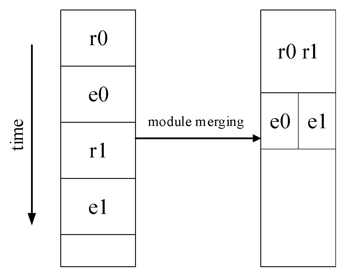
For instance, we assume the region has enough area to accommodate the reconfiguration node in Figure 3.
Noting that r i represents the reconfiguration phase of the task n i in RN k , and e i is the execution phase. In the figure, the vertical direction represents the flow of time. When a region accommodates some reconfiguration nodes, each of which is comprised of a single task, the reconfiguration time of left subgraph is longer than the right subgraph. Owing to the usage of module merging, in the left subgraph, a few tasks are merged into one reconfiguration node so that they can be reconfigured in the same time on the region and different tasks can be carried out in parallel in some cases. Hence, this method decreases the SL.

4. The Reconfiguration-Dependency Non-Consistent Algorithm Based on Simulated Annealing (RDNC-SA)

In this section, we describe the proposed RDNC-SA algorithm for the studied problem. To improve the performance, the module merging technique is integrated into the proposed method. In the following, we will describe the structural framework of the algorithm firstly, and then illustrate each part of the algorithmic framework in detail.

4.1. Structure of the Simulated Annealing Algorithm

The simulated annealing (SA) algorithm is a widely used approach for solving unconstrained and bound-constrained optimization problems. It can jump out of the local optimal solution and feature the ability to search the global solution space. We developed an effective algorithm based on SA for the partitioning and scheduling problem on the DPR-FPGA, with the algorithmic structure being shown in Figure 4.
As shown in the figure, SA algorithm incorporates seven main steps and two iterative loops which are the cooling procedure for the annealing process and Metropolis criterion. The main steps of SA are described in detail below:
  • A feasible solution is generated randomly as the initial solution.
  • Then it is disturbed to search for a new solution in the solution space. If a feasible solution is found, the reconfiguration order and the mapping relationship between task and region can be obtained simultaneously. The number of regions and resource types are determined by the mapping relationship.
  • When a feasible solution is obtained, we need to calculate its objective function f.
  • the difference of the objective value Δ E between the new solution and the former one is calculated;
  • According to Metropolis criterion described in the below, whether to accept the new solution is judged.
    p = 1 , Δ E < 0 e Δ E T Δ E 0
  • The next step is to judge the number of iterations in the inner loop is reached.
  • Determine whether the termination condition is reached after the end of the inner loop iteration. If not, the algorithm would cool the temperature and continue to produce new solutions. Otherwise, the optimal solution is returned.
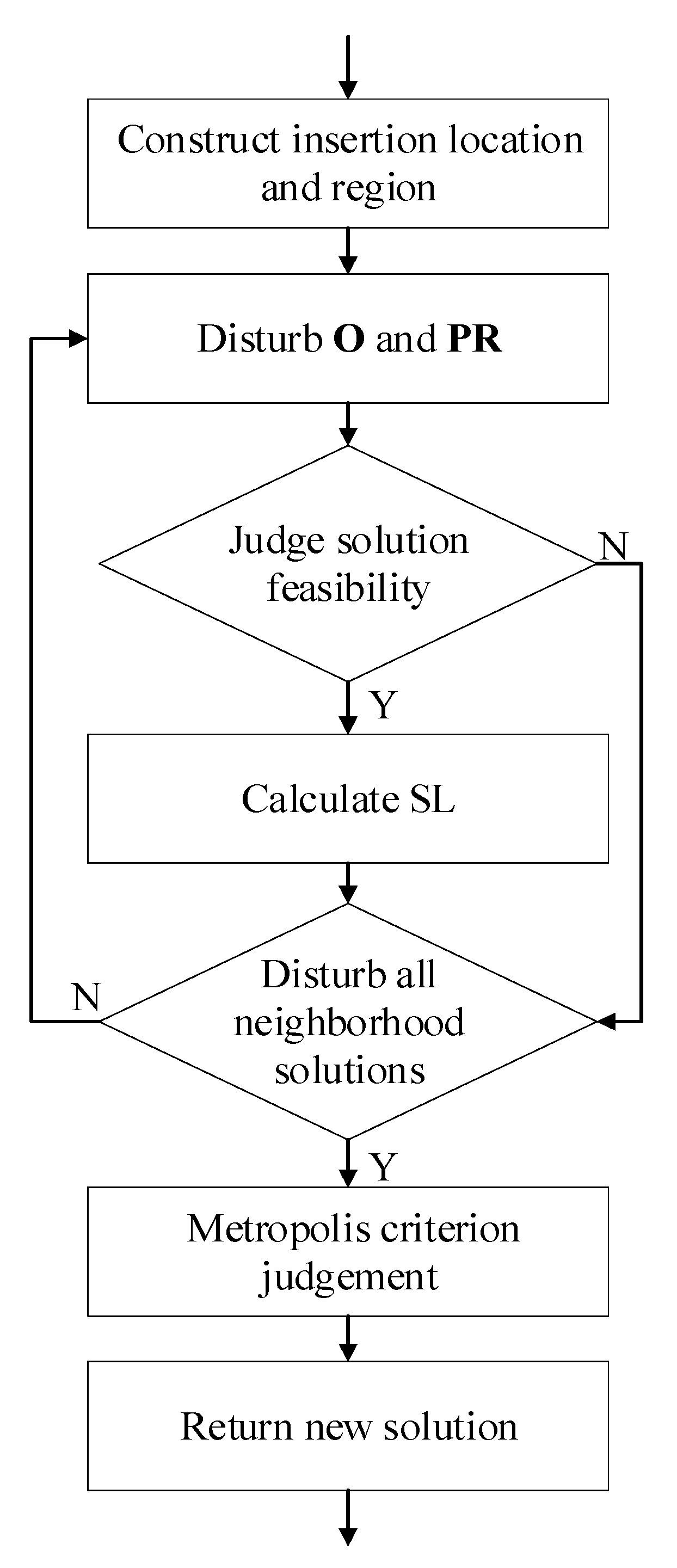
In the whole algorithm based on SA, disturbing the current solution to generate a new solution is the most important part. In order to generate high-quality new solutions, we design this part carefully, with the entire framework being shown in Figure 5. In the following subsections, we will introduce the key steps of the process in detail.

4.2. Solution Structure

In the proposed algorithm, the solution of the partitioning and scheduling problem is encoded in a solution structure that comprises two parts: task-to-region allocation and task reconfiguration order. Noting that this solution structure does not encode all aspects of the solution, and other aspects of the full solution to the target problem, e.g., region partitioning, task execution time, reconfiguration time and module merging strategy, should be derived from the solution structure.
Task-to-region allocation is denoted as PR i = { R N 0 , R N 1 , . . . , R N m } , and i represents the label of the task mapping to the region. PR i includes a number of reconfiguration nodes which is mapped to this region. It clearly shows the mapping relationship between tasks and regions. Every region has its own attributes, such as region size and region resource types. Region size depends on the all reconfiguration nodes’ maximal requirement about a certain resource type.
The reconfiguration order is denoted as O. As mentioned before, each reconfiguration node corresponds to a unique ROV, and tasks within a node have a common ROV. O is a two-dimensional vector composed of several one-dimensional vectors, each of which can be interpreted as a location to store the reconfiguration nodes. Each location has a unique number called ROV which is used to represent the reconfigurable order of each reconfiguration node. ROV stands for the priority of the node during reconfiguration phase. The smaller ROV stand for the higher the priority and the earlier the reconfiguration phase occurs. Reconfiguration nodes are arranged in O according to the value of ROV. Because each location holds a reconfiguration node, single location can possess one or more tasks that share the same ROV.

4.3. Disturbance Method with Module Merging

In this subsection, in conjunction with the previous content, we specifically elaborate disturbance method with module merging.
In order to ensure the complete coverage of the solution space, the whole disturbance process is divided into two parts: first, single task n d is selected to disturb, and then module merging with n d .
First of all, selecting a task n d randomly as a new reconfigured node and disturbing the current solution which are the necessary steps for generating new solution. The disturb method is “Insert After Remove (IAR)” proposed in [29]. The action of disturbing solution is divided as two parts including disturb reconfiguration order O and PR. Therefore, the specific operation of IAR is to delete a reconfiguration node in O and region PR, and then insert the reconfiguration node in a certain position of O and PR.
In the variant of O , n d can be inserted into a new location in O called candidate location after it is deleted from its primary location, which means it gives n d a new ROV. After finishing the disturbance of O, it as well needs to disturb PR. We should remove n d from its primary belong region and insert it into a new region.
Then, merging n d with a reconfiguration node below its location in O. It also means n d and that reconfiguration node have the same ROV. Noting that when the location of n d is in the back of O, which represents there is no reconfiguration node below its location, it will be merged with the previous one. The same merge motion should be occurred in region as well. We remove all tasks among reconfiguration node and n d and put them into the uniform region. In the meantime, n d and the reconfiguration node form a new reconfiguration node in the solution.

4.4. Solution Feasibility Evaluation

The partial solution to the target problem modeled by the solution structure introduced in the former subsection may be infeasible. Since evaluating the solution feasibility before SL computation is essential, we analyze the feasibility of the partial solution in this subsection.
Two kinds of infeasible conditions for the partial solution are considered in the model, i.e., the resource conflicting condition and the execution infeasible condition.

4.4.1. Resource Conflicting Condition

As described in Equation (5), there is a resource constraint relationship between regions and FPGA. When the sum of any resource type of all regions exceeds the resource volume of the FPGA, we call this solution the resource infeasible solution.

4.4.2. Execution Infeasible Condition

In a solution, if the task cannot get the data of the parent tasks according to the dependency relationship during the execution of the task, we call this solution the execution infeasible solution. To clearly describe this condition, several definitions are introduced to describe the relationship between different tasks of the application.
Definition 1.
If the ROV of a certain task is greater than any ancestor task or less than any descendant task, we call this case the reverse order.
Definition 2.
Definition 2. If the ROV of a certain task is less than or equal to all ancestor tasks and greater than all descendant tasks, we call this case the positive order.
Definition 3.
Definition 3. The reconfiguration-adjacent node of n i is the reconfiguration node that is rightly reconfigured after n i on the same region. The tasks in the node are called reconfiguration-adjacent tasks. Noting that n i and its reconfiguration-adjacent node RN j should be mapped to the same region, and no other node is reconfigured between n i and RN j .
Based on the above definitions and the previous analysis of the solution structure, we give a lemma to indicate under what conditions the solution is a feasible solution.
Lemma 1.
For a task n i , n i and its ancestor tasks cannot be in reverse order relationship in the same region, and if the reconfiguration-adjacent task of n i exists, it cannot be reconfigured before any ancestor task of n i .
For any two different tasks n i and n j , we assumed that n i is an ancestor task of n j . As we know, a sufficient and necessary condition for an execution feasible solution is that the task can obtain the data it needs in a limited time. Hence, when a task can be executed, it must have obtained the data of all parent tasks. And when its parent tasks can be executed, they must have obtained the data of all grandparent tasks, and so on. We conclude that n j must not be executed if any ancestor task n i is not executed.
As the previous analysis, a solution consisted of reconfiguration order and task-to-region allocation. For two tasks, the reconfiguration order relationship can be divided into reverse order and positive order and task-to-region allocation relationship can be grouped into in the same region and in the different region.
For positive order, regardless of whether the task is in the same region, its corresponding solution must be a feasible solution. When n i and n j belong to the same region because of positive order, it is obvious that n i carried out execution phase before n j . In different region, n j must obtain its parents data before its reconfiguration-adjacent tasks start to reconfigured. Because execution must be feasible when the reconfiguration order is positive order. So, there must be feasible solutions.
For reverse order, we assume that the tasks are in the same region and the reconfiguration-adjacent node of n j exists. Before reconfiguration phase of the reconfiguration node which n j belong starts, since n i has not started the reconfiguration and execution, at least one parent task of n j cannot be executed, which leads to n j unable to execute. Therefore, the region where n j is located will be in the waiting state after n j reconfiguration. Since the reconfiguration of n i is latter than n j in the same region, the region will reconfigured before n j starts the execution phase. Hence, the descendant task n j will never wait for its parent data. For the different region situation, as mentioned earlier, n j needs to wait for the data of the parent tasks after reconfiguration because the parent tasks of n j is not fully executed. However, the reconfiguration-adjacent node reconfigures before n i . When n j does not get n i data, its reconfiguration region has been reconfigured. Hence, n j cannot obtain its parent tasks data.
In order to have a better understanding, we have drawn a schematic diagram of DAG as an infeasible solution in Figure 6a. In the figure, time is represented in the vertical direction, and different regions are represented in the horizontal direction. The reconfiguration order of Figure 6b is O = { n 0 , n 3 , ( n 1 , n 2 )}. The mapping relationship between tasks and regions is PR 0 = { n 3 , ( n 1 , n 2 ) } , PR 1 = { n 0 } . For ease of presentation, we enclose the reconfiguration nodes containing multiple tasks in parentheses to indicate that they belong to the same reconfiguration node. It can be seen from Figure 6a that n 0 , n 1 are the ancestor tasks of n 3 . Only if executions of n 0 and n 1 are fully completed can n 3 start execution. However, at this time, n 1 and n 3 are in the reserved order in the same region. As stated in Lemma 1, when the ancestor task n 1 and the descendant task n 3 in the same region and have the relationship of reserved order, this solution is not feasible. Because after n 3 ends the reconfiguration phase, the execution phase cannot start immediately. It needs to wait for the data of all parent tasks. However, for n 3 , the data of the parent task n 1 has not been obtained, the reconfiguration of the node RN = { n 1 , n 2 } is started on P R 0 . The execution phase of n 3 disappears. Therefore, this solution is infeasible.
The reconfiguration order of Figure 6c is O = { n 0 , n 3 , n 2 , n 1 }. The task-to-region allocation is PR 0 = { n 0 , n 3 , n 2 } , PR 1 = { n 1 } . According to the mapping relationship and reconfiguration order, we can know that n 3 and n 1 are in reverse order and in different regions. n 2 is the reconfiguration-adjacent tasks of n 3 , and the reconfiguration order of n 2 is earlier than n 1 . After the reconfiguration of n 3 , the region is reconfigured before n 3 obtained n 1 data. Therefore, this type of solution is also infeasible.

4.5. Scheduling Length Calculation

As mentioned, SL is a important parameter when measuring the feasible solution quality. The smaller SL means the better solution; otherwise, the solution has worse quality.
When the obtained solution is a feasible solution, the scheduling length needs to be calculated to evaluate the solution. We present pseudo code to calculate the length of the scheduling, as shown in Algorithm 1.
O and PR have decided the entire solution, we need to calculate the scheduling length according to the reconfiguration order and the mapping relationship between tasks and regions. For each reconfiguration node, it is necessary to calculate R s and E s , and then calculate R e and E e according to expression (2) and (3). When calculating the execution start time, if the parent task of a task of the current reconfiguration node has not yet started or has not been completed, this task needs to be pushed into the waiting queue Q. In the next step, the algorithm is going to continue to calculate the start time of the other nodes. When the parent tasks of the waiting task are all executed, they can start to execute the waiting task. The reconfiguration start time of the first reconfiguration node is set to 0, then formula (9) is simplified to S L = m a x ( E e i ) , that is, the scheduling length is the execution end time of the last reconfiguration node.
Algorithm 1 Calculate scheduling length
1:
Reset each task R s , R e , E s , E e .
2:
for each R N i O do
3:
for each n j R N i do
4:
  compute R s and R e of n j .
5:
  if all p n of n j has accomplished execution phase do
6:
   compute E s and E e of n j .
7:
  else
8:
   push n j into the waiting queue Q .
9:
  end if
10:
end for
11:
for each n j Q do
12:
  Repeat the steps in lines 5 and 6
13:
  end if
14:
end for
15:
end for
16:
Assign the maximum execution end time E e j to SL.
17:
return SL

4.6. New Solution Based on Neighborhood Solution Set

Generating a new solution based on the current solution in each iteration is a key step in the SA algorithm. We develop a novel new solution generation approach based on the neighborhood solution set. The new solution is selected from the neighborhood solution set with a specific rule.
The steps for generating the neighborhood solution set are as follows:
  • Before disturbing n d , we need to select a set of insertion locations for n d in O. The ROV corresponding to these locations is a set of non repeating values. Similarly, a set of non repeating insertion regions is also selected in PR.
  • Each location and region to be inserted for n d is arranged to form a number of unique pairs denoted as Pair. Each element of Pair is denoted as p a i r i . Insert n d into the O and PR positions of each p a i r i . A solution is formed after each disturbance. After the feasibility analysis of the solutions formed by each disturbance, the SL of each feasible solution is calculated. we need to save feasible solutions and corresponding SL.
  • After all of the neighborhood solutions solved, we compared total solution SL to the minimum SL of solution and selecting one as return value according to Metropolis criterion. Noting that this process of selecting is different SA main process. In here, it is only a select strategy for returning a solution from neighborhood. After returning a solution, the SA main process still needs to judge whether reception this new solution as current solution according to Metropolis criterion.
The above sub-sections constitute the new solution generation algorithm. In the algorithm, because the insertion location for n d in O is not related to the the data dependency in DAG, we call this algorithm reconfiguration-dependency non-consistent algorithm (RDNC-SA), the pseudo code of this algorithm is presented in Algorithm 2.
Algorithm 2 Reconfiguration-dependency non-consistent algorithm (RDNC-SA)
1:
for each insertLocation do
2:
for each insertRegion do
3:
  Disturb( n d , insertLocation, insertRegion, O, PR).
4:
  exeFeasibility = JudgeExeFeasibility( n d , O, PR).
5:
  if exeFeasibility == True then
6:
   resFeasibility = JudgeResFeasibility( n d , O, PR).
7:
   if resFeasibility == True then
8:
    Calculate scheduling Length.
9:
    Preserve insertLocation and insertRegion.
10:
   end if
11:
  end if
12:
end for
13:
 ModuleMerge( n d , O, PR)
14:
for each insertRegion do
15:
  Disturb( n d , insertLocation, insertRegion, O, PR).
16:
  exeFeasibility = JudgeExeFeasibility( n d , O, PR).
17:
  if exeFeasibility == True then
18:
   resFeasibility = JudgeResFeasibility( n d , O, PR).
19:
   if resFeasibility == True then
20:
    Calculate scheduling Length.
21:
    Preserve insertLocation and insertRegion.
22:
   end if
23:
  end if
24:
end for
25:
end for

5. The Reconfiguration-Dependency Consistent Algorithm Based on Simulated Annealing (RDC-SA)

In order to reduce the time complexity of judging the feasibility of the solution, we develop a new algorithm in this section. Different from the RDNC-SA, the insertion location is related to the data dependency in DAG. Therefore, we call it the reconfiguration-dependency consistent algorithm. The RDC-SA does not have to make a feasible judgement, thus reducing the computation cost. In the following, we introduce this algorithm in detail.
During generating the neighborhood set, RDC-SA follows the data dependency of the DAG while constructing the location where task n d is going to be inserted. The candidate location set is comprised of a series of well-ordered ROVs, whose left value is the maximum ROV of the set of parents of n d , and the right value is the minimum ROV of the set of children of n d , which guarantees O to be a positive order and avoids the occurrence of infeasible solutions.
RDC-SA can ensure the reconfiguration phase of PN d can be carried out before n d itself, and  CN d reconfiguration phase can be performed after n d . Hence, in the phase of execution, all tasks can obtain data from the parent tasks before execution. Then, it still needs to judge the resource conflicting condition and decide whether we need to calculate the SL. After disturbing all insertion regions for each insertion location, the next step is module merging which method is the same as before. The new reconfiguration node will be inserted into each insertion region. And we also have to judge the resource constraint to determine whether to calculate the SL. Algorithm pseudo code is presented in Algorithm 3.
Algorithm 3 Reconfiguration-dependency consistent algorithm based on simulated annealing (RDC-SA)
1:
for each insertLocation do
2:
for each insertRegion do
3:
  Disturb( n d ,insertLocation, insertRegion, O, PR).
4:
  resFeasibility = JudgeResFeasibility( n d , O, PR).
5:
  if resFeasibility == True then
6:
   Calculate scheduling Length.
7:
   Preserve insertLocation and insertRegion.
8:
  end if
9:
end for
10:
 ModuleMerge( n d , O, PR)
11:
for each insertRegion do
12:
  Disturb( n d ,insertLocation, insertRegion, O, PR).
13:
  resFeasibility = JudgeResFeasibility( n d , O, PR).
14:
  if resFeasibility == True then
15:
   Calculate scheduling Length.
16:
   Preserve insertLocation and insertRegion.
17:
  end if
18:
end for
19:
end for
Compared with RDNC-SA, the key advantage of RDC-SA exists in solving time. The RDC-SA algorithm is advantageous over RDNC-SA due to its respect to the data dependency while constructing the reconfiguration order. All individuals of the RDC-SA solution space are execution-feasible solution. However, RDNC-SA encounters lots of infeasible solutions about execution when searching the solution space. Hence, RDNC-SA has a larger solution space to search. Therefore, RDNC-SA has to judge the feasibility of all found solutions at the cost of solving time.

6. Experiment Result

In this section, we verify the performance of constructing neighborhood solution set at first compared with random selection. In addition, we compare the proposed RDNC-SA and RDC-SA with the state-of-art work, i.e, MILP [23], IS-k [23] and ACO [18]. In [23], The authors accurately solve the target problem by constructing a MILP model. However, the time complexity of the MILP method is high, so that the solution efficiency is low. The authors also propose the IS-k algorithm with lower time complexity. But in some cases, IS-k solving results are worse than MILP. Therefore, we believe that IS-k is a trade off between solution quality and solving time. Ref [18] utilizes ACO to solve the solution, but it does not optimize the algorithm further, and the performance of the algorithm is not fully compared in the experiment. In order to compare the performance of different algorithms, we take the solving time and SL as the measurement indicators.
In our experiment, we selected a set of practical applications which were extracted directly from [30,31,32] and modeled them as DAG. The application name and task number are presented in Table 2. As shown in the table, the number of tasks varied from 8 to 50, which can cover the scale of most real-life applications. The resource consumption of the execution time of the task in each application was selected between the maximum and minimum values. Tasks execution time varied from 100 to 2000, and resource usage was uniformly distributed between 1 and 100. For the resource ratio of each application to the target platform, we set the FPGA resource amount to 40% of the total task resource amount in each DAG.
The proposed algorithms were implemented in C++ language which were run on a PC which contained Intel Xeon Silver 4110CPU (16 cores, 32 threads) with Ubuntu 18.04 OS, 32 GB RAM. It worked at a frequency of 2.10 GHz. We used Gurobi [33] as the ILP solver. As a result of the solving method of MILP is time consuming, the upper limit of solving time denoted as t i m e o u t was set for the solver for each DAG to make sure the solver could return the best solution obtained within a limited time.

6.1. Target Platform Configuration

In the experiment, our target platform, Xilinx XC7Z020, was an FPGA with DPR capability. As described in Section 3, the reconfiguration data of the FPGA regions were transmitted by ICAP which was 32-bit and had a clock of 100 MHz. According to the configuration frame number and size, we evaluated the time overhead of reconfiguring single unit CLB, DSP and BRAM as 73.8, 287, 307.5 clock cycles respectively. The reconfiguration time was proportional to the amount of resources required by the reconfigurable region in which the new hardware accelerator had to be allocated [34]. To reduce the complexity of solving the ILP formulation, in the experiment, the execution time and reconfiguration overhead of different resources were both divided by 10. So, the reconfiguration overhead of one CLB, DSP and BRAM was 7, 28, 30 respectively.

6.2. Parameter Setup

For MILP and IS-k, we set the value of t i m e o u t as 1800 s. In addition, we set k = 8 as the number of the subset tasks for IS-k. The parameters of the cooling scheduling of the simulated annealing algorithm were initial temperature T 0 = 500 , termination temperature T e = 10 3 , cooling coefficient α = 0.98 , inner cycle number I L O O P = 10 .

6.3. Performance Analysis of Neighborhood Solution Set

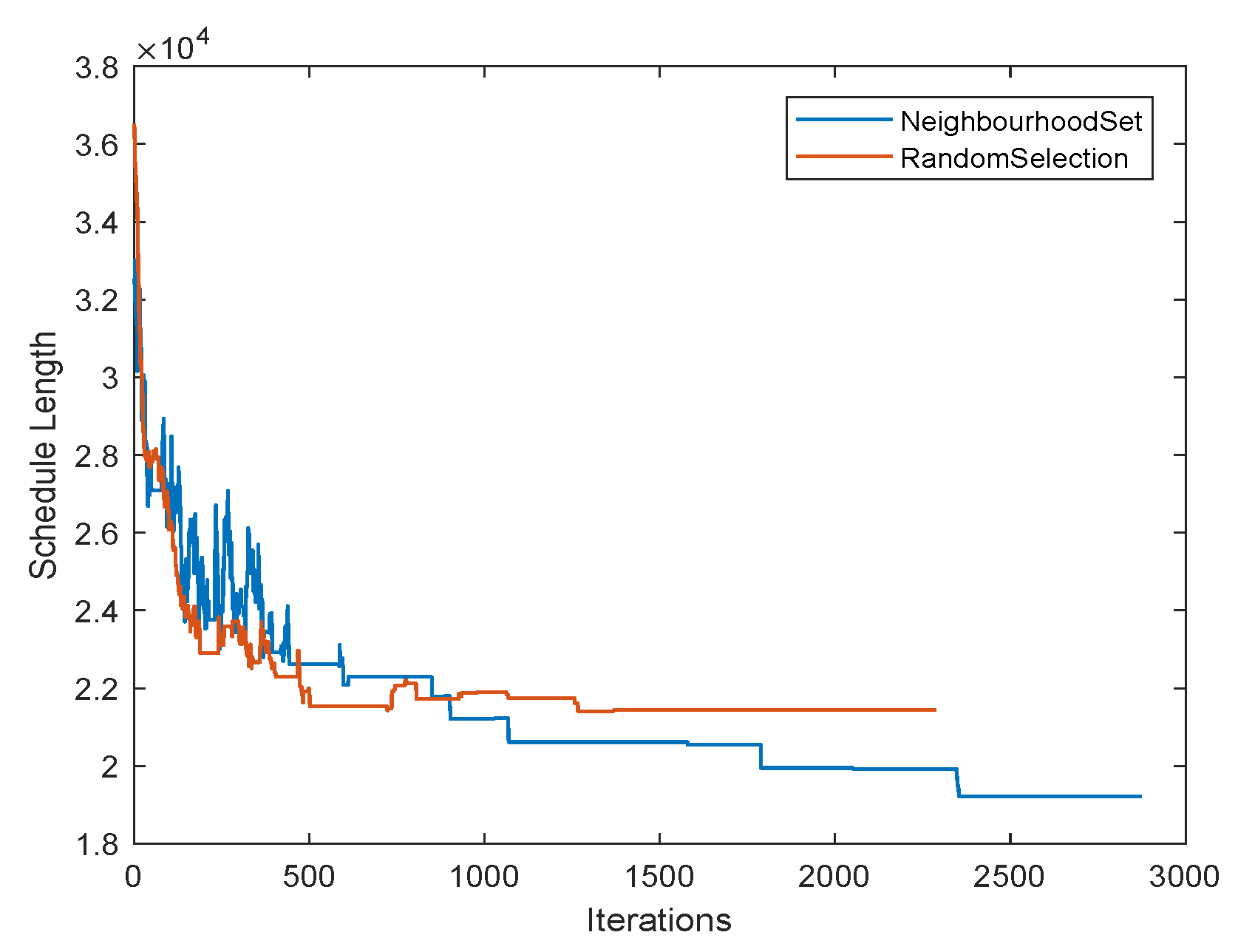
We compared the two methods of generating new solutions which are construct neighborhood solution set and random selection for a DAG. Experiment shows that constructing a neighborhood solution set had good performance in the aspect of solving the optimal solution based on SA algorithm. Not only could it make the solution result converge rapidly, but it could also find a better solution than not constructing a neighborhood solution set. The comparison chart of the experimental results as shown in the Figure 7.
As shown in the figure of the iterative convergence graph, the abscissa indicates the number of iterations, and the ordinate indicates the objective function SL. It can be seen from the observation that although the red curve drops faster than the blue curve at the early stage of the iteration, the fluctuation was smaller at the later stage of the iteration. The blue curve showed an exponential decline in the early stage as with the random selection method. Although there were large fluctuations in the initial stage, after the number of iterations reached about 800, it exceeded the random selection method to obtain a better value. In the subsequent solving process, SL still showed a stepwise decline. Finally, we can conclude that the method of constructing the neighborhood solution could converge earlier and eventually converged to a value that was better than random selection.

6.4. Performance Analysis of Different Algorithms

In order to more clearly show the relative sizes of SL solved by different methods, Performance Improvement Ratio (PIR) was introduced to represent the relative difference of SL as follows:
P I R = S L S A S L o t h e r S L o t h e r
When P I R = 0 , SA-based algorithm had the same scheduling length as other algorithm;
When P I R < 0 , the scheduling length solved by SA-based algorithm was better than other algorithm, | P I R | means that the difference between SA-based algorithm and other algorithm accounted for the proportion of other algorithm;
When P I R > 0 , the scheduling length solved by SA-based algorithm was worse than other algorithm. | P I R | represents the proportion of the difference between SA-based algorithm and other algorithm accounts for the proportion of other algorithm.
Table 2 shows data comparisons that RDNC-SA, RDC-SA compared to MILP [23], IS-k [23] and ACO [18]. The resource volume of the FPGA was set as 40% of the aggregate resource requirement of each application. Table 2 consists of five parts. The first part is the name of the application and the number of tasks for each application. The second, third and fourth parts are the solving time of MILP, IS-k and ACO algorithms and the PIR of SL compared with RANC-SA, RDC-SA. The fifth part is RANC-SA and RDC-SA solving time. To facilitate analysis, we divide all applications into three parts according to the number of tasks.
The first part is application task number ∈ (0, 10]. From the data in the table, we can know that the PIR of MILP and IS-k were both −3%. The solving time of MILP, IS-k and RDC-SA were all less than 1 s, but RDNC-SA is 31.96 s.
The second part is task number ∈ (10, 30]. In this part, the average value of RDNC-SA PIR of all DAGs was −10%, −12%, −38% corresponding to MILP, IS-k and ACO. Most solving time in MILP reached timeout. Except for the application Cyber Shake, RDNC-SA solving time was longer than IS-k. Although the solving times of ACO were all about 4 s, there was a big gap that the PIR was −38% compared to RDNC. Compared with RDC-SA, the average values of PIR were −9%, −11%, −37% corresponding to MILP, IS-k and ACO, and the solution time of all DAGs was less than MILP, IS-k and ACO. This also means that the RDC-SA solved a better quality solution in a shorter time.
The third part is task number ∈ (30, 50]. As the number of tasks increased, the advantages of our proposed algorithms became more significant. For the other three algorithms, the average value of RDNC-SA PIR was −20%, −11%, −37%, and the average value of RDC-SA PIR reached −18%, −10%, −36% respectively. In terms of solving time, our proposed RDC-SA and RDNC-SA were shorter than MILP and IS-k.
On the whole, the two algorithms proposed in this paper were more efficient in solution quality and solving time. Compared with MILP and IS-k, for RDNC-SA algorithm, the average solving time was 60.6s, which reduced 96% and 76% of the time cost respectively. In terms of solving quality, it was 11% better than MILP and IS-k. For RDC-SA algorithm, its average solving time was 1.26 s which was much shorter than the other two algorithms. This algorithm also got the same 11% higher solution quality almost instantly. Compared with ACO, the solving results of our two algorithms were 37% better than ACO. Therefore, although ACO had a shorter solving time, its solving results had no performance advantage. These two algorithms could efficiently solve the most approximate solution. Since our proposed algorithms were based on SA, the solving time of algorithms was only related to the number of tasks. In contrast, the ILP-based methods were related to multiple factors such as the number of variables, the number of tasks, and the data values of task attributes. Moreover, we utilized some optimization strategies to improve the solution quality. Hence, our results were better than the other algorithms.

7. Conclusions

Compared with other researches, our research considers many physical constraints of resource partitioning and application scheduling, and establishes a DPR system model close to reality. We design two algorithms which can solve the task reconfiguration order and task-to-region allocation. And compared with other algorithms, they can solve a better quality solution in a shorter solving time, which greatly improves the efficiency of the solution. The next step of our study is taking power consumption and floorplanning into account in our DPR system model.

Author Contributions

Z.W. and Q.T. conceived and designed the experiments; Z.W. performed the experiments; L.W. and J.-B.W. analyzed the data; B.G. contributed reagents/materials/analysis tools; Z.W. wrote the paper. All authors have read and agreed to the published version of the manuscript.

Funding

This research received no external funding.

Conflicts of Interest

The authors declare no conflict of interest.

References

  1. Nurvitadhi, E.; Sheffield, D.; Sim, J.; Mishra, A.; Venkatesh, G.; Marr, D. Accelerating binarized neural networks: Comparison of FPGA, CPU, GPU, and ASIC. In Proceedings of the 2016 International Conference on Field-Programmable Technology (FPT), Xi’an, China, 7–9 December 2016. [Google Scholar]
  2. Xilinx. Available online: https://www.xilinx.com/support/documentation/sw_manuals/xilinx2020_1/ug909-vivado-partial-reconfiguration.pdf (accessed on 23 June 2020).
  3. Kara, K.; Alistarh, D.; Alonso, G.; Mutlu, O.; Zhang, C. FPGA-accelerated dense linear machine learning: A precision-convergence trade-off. In Proceedings of the 2017 IEEE 25th Annual International Symposium on Field-Programmable Custom Computing Machines (FCCM), Napa, CA, USA, 30 April–2 May 2017. [Google Scholar]
  4. Njiki, M.; Elouardi, A.; Bouaziz, S.; Casula, O.; Roy, O. A multi-FPGA architecture-based real-time TFM ultrasound imaging. J. Real Time Image Process. 2019, 16, 505–521. [Google Scholar] [CrossRef]
  5. Lentaris, G.; Stratakos, I.; Stamoulias, I.; Soudris, D.; Lourakis, M.; Zabulis, X. High-performance vision-based navigation on SoC FPGA for spacecraft proximity operations. IEEE Trans. Circuits Syst. Video Technol. 2019, 30, 1188–1202. [Google Scholar] [CrossRef]
  6. Dhar, A.; Yu, M.; Zuo, W.; Wang, X.; Kim, N.S.; Chen, D. Leveraging Dynamic Partial Reconfiguration with Scalable ILP Based Task Scheduling. In Proceedings of the 2020 33rd International Conference on VLSI Design and 2020 19th International Conference on Embedded Systems (VLSID), Bangalore, India, 4–8 January 2020. [Google Scholar]
  7. El Cadi, A.A.; Souissi, O.; Atitallah, R.B.; Belanger, N.; Artiba, A. Mathematical programming models for scheduling in a CPU/FPGA architecture with heterogeneous communication delays. J. Intell. Manuf. 2018, 29, 629–640. [Google Scholar] [CrossRef]
  8. Saha, S.; Sarkar, A.; Chakrabarti, A. Scheduling Dynamic Hard Real-Time Task Sets on Fully and Partially Reconfigurable Platforms. IEEE EMBED Syst. Lett. 2015, 7, 23–26. [Google Scholar] [CrossRef]
  9. Charitopoulos, G.; Koidis, I.; Papadimitriou, K.; Pnevmatikatos, D. Hardware task scheduling for partially reconfigurable FPGAs. In Proceedings of the International Symposium on Applied Reconfigurable Computing, Bochum, Germany, 13–17 April 2015; Springer: Berlin/Heidelberg, Germany, 2015; pp. 487–498. [Google Scholar]
  10. Salamy, H.; Aslan, S. A genetic algorithm based approach to pipelined memory-aware scheduling on an MPSoC. In Proceedings of the 2015 IEEE Dallas Circuits and Systems Conference (DCAS), Dallas, TX, USA, 12–13 October 2015. [Google Scholar]
  11. Ramezani, R. A prefetch-aware scheduling for FPGA-based multi-task graph systems. J. Supercomput. 2020, 76, 7140–7160. [Google Scholar] [CrossRef]
  12. Resano, J.; Mozos, D.; Catthoor, F. A hybrid prefetch scheduling heuristic to minimize at run-time the reconfiguration overhead of dynamically reconfigurable hardware [multimedia applications]. In Proceedings of the Design, Automation and Test in Europe, Munich, Germany, 7–11 March 2015. [Google Scholar]
  13. Clemente, J.A.; Beretta, I.; Rana, V.; Atienza, D.; Sciuto, D. A mapping-scheduling algorithm for hardware acceleration on reconfigurable platforms. ACM Trans. Reconfig. Technol. Syst. TRETS 2014, 7, 1–27. [Google Scholar] [CrossRef] [Green Version]
  14. Kim, J.J.; Yang, H.M.; Ryu, K.H.; Kim, H.S. FPGA Low Power Technology Mapping for Reuse Module Design under the Time Constraint. In Proceedings of the 2008 Second International Conference on Future Generation Communication and Networking, Sanya, Hainan, China, 13–15 December 2008. [Google Scholar]
  15. Clemente, J.A.; Resano, J.; Mozos, D. An approach to manage reconfigurations and reduce area cost in hard real-time reconfigurable systems. ACM Trans. Embed. Comput. Syst. TECS 2014, 13, 1–24. [Google Scholar] [CrossRef] [Green Version]
  16. Ma, Y.; Liu, J.; Zhang, C.; Luk, W. HW/SW partitioning for region-based dynamic partial reconfigurable FPGAs. In Proceedings of the 2014 IEEE 32nd International Conference on Computer Design (ICCD), Seoul, Korea, 19–22 October 2014. [Google Scholar]
  17. Dorflinger, A.; Albers, M.; Schlatow, J.; Fiethe, B.; Michalik, H.; Keldenich, P.; S’andor, P.F. Hardware and software task scheduling for ARM-FPGA platforms. In Proceedings of the 2018 NASA/ESA Conference on Adaptive Hardware and Systems (AHS), Edinburgh, UK, 6–9 August 2018. [Google Scholar]
  18. Ferrandi, F.; Lanzi, P.L.; Pilato, C.; Sciuto, D.; Tumeo, A. Ant colony optimization for mapping, scheduling and placing in reconfigurable systems. In Proceedings of the 2013 NASA/ESA Conference on Adaptive Hardware and Systems (AHS-2013), Torino, Italy, 24–27 June 2013. [Google Scholar]
  19. Sun, Z.; Zhang, H.; Zhang, Z. Resource-Aware Task Scheduling and Placement in Multi-FPGA System. IEEE ACCESS 2019, 7, 163851–163863. [Google Scholar] [CrossRef]
  20. Sahoo, S.S.; Nguyen, T.D.; Veeravalli, B.; Kumar, A. Multi-objective design space exploration for system partitioning of FPGA-based Dynamic Partially Reconfigurable Systems. Integration 2019, 67, 95–107. [Google Scholar] [CrossRef]
  21. Biondi, A.; Buttazzo, G. Timing-aware FPGA partitioning for real-time applications under dynamic partial reconfiguration. In Proceedings of the 2017 NASA/ESA Conference on Adaptive Hardware and Systems (AHS), Pasadena, CA, USA, 24–27 July 2017; pp. 172–179. [Google Scholar]
  22. Zhou, T.; Pan, T.; Meyer, M.C.; Dong, Y.; Watanabe, T. An Interval-based Mapping Algorithm for Multi-shape Tasks on Dynamic Partial Reconfigurable FPGAs. In Proceedings of the 2020 IEEE International Parallel and Distributed Processing Symposium Workshops (IPDPSW), Portland, OR, USA, 17–21 May 2020. [Google Scholar]
  23. Deiana, E.A.; Rabozzi, M.; Cattaneo, R.; Santambrogio, M.D. A multiobjective reconfiguration-aware scheduler for FPGA-based heterogeneous architectures. In Proceedings of the 2015 International Conference on ReConFigurable Computing and FPGAs (ReConFig), Mexico City, Mexico, 7–9 December 2015. [Google Scholar]
  24. Ramezani, R.; Sedaghat, Y.; Naghibzadeh, M.; Clemente, J.A. Reliability and makespan optimization of hardware task graphs in partially reconfigurable platforms. IEEE Trans. Aerosp. Electron. Syst. 2017, 53, 983–994. [Google Scholar] [CrossRef] [Green Version]
  25. Bender, M.A.; Farach-Colton, M.; Pemmasani, G.; Skiena, S.; Sumazin, P. Lowest common ancestors in trees and directed acyclic graphs. J. Algorithms 2005, 57, 75–94. [Google Scholar] [CrossRef]
  26. Tang, Q.; Guo, B.; Wang, Z. Sw/Hw Partitioning and Scheduling on Region-Based Dynamic Partial Reconfigurable System-on-Chip. Electronics 2020, 9, 1362. [Google Scholar] [CrossRef]
  27. Xiao, X.; Xie, G.; Li, R.; Li, K. Minimizing schedule length of energy consumption constrained parallel applications on heterogeneous distributed systems. In Proceedings of the 2016 IEEE Trustcom/BigDataSE/ISPA, Tianjin, China, 23–26 August 2016. [Google Scholar]
  28. Tang, Q.; Wang, Z.; Guo, B.; Zhu, L.H.; Wei, J.B. Partitioning and Scheduling with Module Merging on Dynamic Partial Reconfigurable FPGAs. ACM Trans. Reconfig. Technol. Syst. TRETS 2020, 13, 1–24. [Google Scholar] [CrossRef]
  29. Chen, S.; Yoshimura, T. Fixed-outline floorplanning: Block-position enumeration and a new method for calculating area costs. IEEE Trans. Comput. Aided Des. Integr. Circuits Syst. 2008, 27, 858–871. [Google Scholar] [CrossRef]
  30. Tang, Q.; Wu, S.F.; Shi, J.W.; Wei, J.B. Optimization of duplication-based schedules on network-on-chip based multi-processor system-on-chips. IEEE Trans. Parallel Distrib. Syst. 2016, 28, 826–837. [Google Scholar] [CrossRef]
  31. Canon, L.C.; El Sayah, M.; Héam, P.C. A comparison of random task graph generation methods for scheduling problems. In European Conference on Parallel Processing; Springer: Berlin/Heidelberg, Germany, 2019; pp. 61–73. [Google Scholar]
  32. Tang, Q.; Basten, T.; Geilen, M.; Stuijk, S.; Wei, J.B. Mapping of synchronous dataflow graphs on MPSoCs based on parallelism enhancement. J. Parallel Distrib. Comput. 2017, 101, 79–91. [Google Scholar] [CrossRef]
  33. Gurobi. Available online: https://www.gurobi.com/ (accessed on 16 January 2012).
  34. Purgato, A.; Tantillo, D.; Rabozzi, M.; Sciuto, D.; Santambrogio, M.D. Resource-efficient scheduling for partially-reconfigurable FPGA-based systems. In Proceedings of the 2016 IEEE International Parallel and Distributed Processing Symposium Workshops (IPDPSW), Chicago, IL, USA, 23–27 May 2016. [Google Scholar]
Figure 1. Dynamically partially reconfigurable (DPR) system.
Electronics 09 01461 g001
Figure 2. A sample directed acyclic graph (DAG).
Electronics 09 01461 g002
Figure 3. Module merge comparison.
Electronics 09 01461 g003
Figure 4. Simulated annealing (SA) flow.
Electronics 09 01461 g004
Figure 5. Disturb solution.
Electronics 09 01461 g005
Figure 6. Infeasible solution.
Electronics 09 01461 g006
Figure 7. Iterative convergence.
Electronics 09 01461 g007
Table 1. DAG parameter.
Task NameETCLB NumPNCN
n 0 243231-{ n 3 }
n 1 175532-{ n 3 , n 4 }
n 2 154287-{ n 4 }
n 3 146357{ n 0 , n 1 }{ n 5 , n 6 }
n 4 139532{ n 1 , n 2 }{ n 5 }
n 5 19991{ n 3 }{ n 7 }
n 6 256406{ n 3 , n 4 }{ n 7 }
n 7 1714{ n 5 , n 6 }{ n s }
Table 2. Experiment result (resource ratio = 0.4).
ApplicationMILPIS-kACORDNCRDC
App NameTaskNumTimeRDNC-SARDC-SATimeRDNC-SARDC-SATimeRDNC-SARDC-SATimeTime
PIRPIR PIRPIR PIRPIR
JPEG encoder80.39−3%−3%0.36−3%−3%4.01−29%−29%31.960.85
Parallel Gauss Elimination1229.18−12%−10%2.10−13%−11%4.66−43%−42%54.442.4
LU decomposition14 t i m e o u t −8%−8%5.76−8%−8%5.30−34%−34%46.22.29
Parallel Tiled QR factorization141109.05−10%−10%10.12−14%−14%3.08−41%−41%55.341.84
Gauss Elimination14 t i m e o u t −6%−9%7.42−6%−9%4.38−33%−36%75.392.88
Channel Equalizer14102.88−6%−9%3.15−6%−9%5.19−37%−39%96.941.53
Gauss Jordan15 t i m e o u t −8%−6%40.43−17%−15%4.42−35%−34%63.032.69
Quadratic Equation Solver15 t i m e o u t −10%−15%4.49−11%−16%3.91−41%−44%67.730.7
TD-SCDMA16 t i m e o u t −12%−12%32.24−13%−13%3.64−42%−42%46.642.34
FFT16 t i m e o u t −5%−4%115.39−6%−5%3.88−22%−21%124.962.6
Laplace Equation16 t i m e o u t −9%−7%16.73−11%−9%4.22−33%−32%97.172.34
Parallel MVA16 t i m e o u t −14%−10%56.64−18%−15%4.38−33%−30%68.212.96
Ferret20 t i m e o u t −12%0%50.60−14%−3%4.02−45%−38%124.081.23
Cyber Shake20 t i m e o u t −13%−12%1475.25−14%−13%4.94−44%−43%231.614.98
Epigenomics20 t i m e o u t −10%−10%117.74−15%−15%4.16−41%−41%160.322.43
Montage20 t i m e o u t −10%−10%43.83−11%−11%4.26−43%−43%88.792.27
LIGO22 t i m e o u t −12%−10%40.90−12%−10%4.82−43%−42%143.544
WLAN 802.11a Receiver24 t i m e o u t −12%−14%70.63−12%−14%5.06−33%−34%102.731.59
MP3 Decoder Block Parallelism27 t i m e o u t −7%−9%131.32−6%−8%6.41−34%−35%222.844.81
SIPHT31 t i m e o u t −14%−12% t i m e o u t −15%−13%6.25−37%−35%255.167.48
Molecular Dynamics41 t i m e o u t −15%−13% t i m e o u t −14%−13%9.54−32%−32%277.558.89
Modem50 t i m e o u t −30%−30%268.30−6%−5%9.87−42%−41%372.146.86