Article

On the Use of a New Class of Simplified Multi-Window Iris Notch in the Design of Ultra-Compact High-Rejection Waveguide Filters for Satellite Links

Department Ingeniería de Comunicaciones, Edif. Ingeniería de Telecomunicación, University of Cantabria, Plaza de la Ciencia s/n, 39005 Santander, Spain
*
Author to whom correspondence should be addressed.
Electronics 2020, 9(8), 1221; https://doi.org/10.3390/electronics9081221
Submission received: 2 July 2020 / Revised: 20 July 2020 / Accepted: 24 July 2020 / Published: 29 July 2020
(This article belongs to the Section Microwave and Wireless Communications)

Abstract

:
This work introduces a simplified multi-aperture iris notch suitable for designing waveguide filters having an extremely improved compactness/rejection ratio, regarding available solutions, and adequate pass-band performances. The proposed iris architecture, analyzed for the first time, exhibits a unique transmission zero in the waveguide mono-mode bandwidth which can be easily located below or above the pass-band. The frequency of this transmission zero is evaluated in terms of the iris dimensions thus providing useful guidelines for designing filters with suitable responses. As a consequence of this simplified topology, any designed filter can be easily manufactured by cutting along its E-field symmetry plane. This strategy greatly improves the filter’s insertion loss regarding classical implementations based on more complicated arrangements with piled thin metallic sheets. Two exemplary filters have been designed and tested to be used in a high-performance X-band SATCOM terminal with an 80% size reduction with respect to the existing systems. Both filters covering the Rx (7.25–75 GHz) and Tx (7.9–8.4 GHz) sub-bands show a reflection of −25 dB with insertion losses below 1 dB in the pass-band, whereas they present a very sharp out-of-band rejection of at least 90 dB, that is, a 600 dB/GHz slope at X band.

Graphical Abstract

1. Introduction

Satellite communications (SATCOM) are of utmost importance today due to their global coverage that enables data links to be established in remote locations and hard environments where other communications networks fail or cannot be present. Furthermore, some applications such as military or corporative services require private infrastructures that take advantage of dedicated satellite networks to isolate their communications for security reasons. The strengths of these systems are obtained at the expense of costly and bulky complex transceivers working at high frequencies with stringent electrical performances.
Very small aperture terminals (VSATs) are portable stations that provide the capability of transmitting and receiving data to/from a satellite at any location around the world within its coverage area without any specific on-site infrastructure. Therefore, they are very suitable for being mounted on vehicles and thus enabling communication under the worst conditions. Standard frequency bands where VSATs operate are C-band, X-band, Ku-band or Ka-band. Usually, these bands are combined in dual-band VSATs improving their versatility.
The simplified antenna feed network of a typical SATCOM single-band terminal is depicted in Figure 1. In the case of dual-band terminals, this scheme could be repeated for each band including an additional component for frequency separation. In Figure 1, the polarization separation subsystem can be either a septum polarizer, if the transceiver works with circular polarizations, or an orthomode transducer (OMT), if it operates with orthogonal linear polarizations. Without filters, in the first case, the transmission/reception isolation is limited by the antenna input port matching, resulting in values of around 30 dB at most, whereas in the second configuration the isolation is driven by the OMT isolation, around 50 dB. In both situations, the achieved isolation value is far from the typical requirement for such terminals to be operative under hard environments, which is 110 dB or better. For this reason, it is mandatory the use of extremely sharp filters with a very high level of rejection, together with other common in-band characteristics such as minimum insertion loss and good return loss in a mechanically robust configuration capable of handling relative high powers.
At X band, the separation between the receiver (Rx) band (7.25–7.75 GHz) and the transmitter (Tx) band (7.9–8.4 GHz) is very limited and consequently the transceiver’s filters have to achieve at least 90 dB of rejection in just 150 MHz, while around 25 dB of return loss and less than 1 dB of insertion loss are required in the band. These values represent a very demanding performance for these filters if a compact design is aimed. There is a wide variety of filter topologies that may be suitable for this application. Traditionally, VSAT filters are based on iris-coupled cavities [1,2,3,4] or stub-loaded cavities [5,6,7] with a number of sections—the larger the number the more the rejection. Although they have suitable performances, these filter topologies became long in terms of wavelength because they normally use half-wavelength resonators. To alleviate this issue, they are usually bent but they still result in bulky structures. These structures are typically selected for commercially available products. Combline filters [8,9,10] are other useful topologies but again they result in large sizes. Corrugated filters [11,12,13] become a classic alternative solution for obtaining more compact designs where, in some cases, their capacitive irises may represent a power handling limitation. Another type of high-rejection filters for these applications are those based on slant resonators [14] or metallic posts [15]. These filters represent a noticeable step forward in terms of compactness but they are rather narrow band.
Single-aperture [16,17] or multi-aperture [18,19,20,21] irises have been extensively studied for the design of a variety of filter types since these structures have the ability to produce transmission and/or reflection zeros at controlled frequencies. Single irises in [16,17] exhibit a band-pass resonant characteristic without E- and H-plane symmetries at the same time, which may result in the appearance of high-order modes. Furthermore, the absence of notch elements in these designs entails the necessity of a very large number of sections to accomplish the required rejection values needed in the intended applications. Although these works provide a comprehensive theoretical analysis of the resonances produced by a particular iris, the practical implementations in real applications are very limited. In [20], the theoretical approach is validated with the measurement of different iris configurations machined in thin metallic sheets but, unfortunately, they are not applied to real filters. In [22], selective windows with complicated arrangements are characterized and applied to different filters showing good performances. In general, the implementations of these multi-aperture irises are in the form of metallic sheets squeezed between straight waveguide sections which complicates the filter mechanical design and has an undesired impact on its insertion loss regarding more convenient strategies such as dividing the filter by its E-field symmetry plane. Moreover, filter designs based on these structures [16,17,18,22] use λg/4 hollow waveguide sections between irises, being λg the waveguide wavelength at the center frequency, which may produce long filters if the number of sections is large.
Recently, in [23,24] an excellent and flexible methodology for the synthesis of bandpass microwave filters with dispersive coupling has been introduced. Authors use asymmetric transmission zeros geometries which are close to the symmetrical ones proposed in this paper. These references use half-wave resonators between discontinuities which implies very long physical designs for the same degree of rejection. Unfortunately, this feature is not compatible with the highly compact concept necessary in specific SATCOM terminals.
The advantages of a simplified multi-aperture iris are analyzed and demonstrated in this work. The proposed iris geometry, although similar at first sight to other previously analyzed structures in [16,17,18,19,20,21,23,24] or classical references [25,26], presents some mechanical differences and has not been directly analyzed before. This iris shows a pure transmission zero at a given frequency, fz, which can be easily controlled with the iris dimensions. Therefore, by including additional waveguide sections for coupling, the desired filter response can be accomplished. Furthermore, the natural short length of these coupling sections enables to obtain filters with a record in the compactness/rejection slope ratio regarding other available solutions. From the mechanical point of view, this iris topology exhibits an improved simplicity. It can be accurately manufactured by standard milling techniques and it is suitable for being integrated in rectangular waveguides in such a way that the whole structure can be easily divided in two halves along its E-field symmetry plane. This strategy minimizes the insertion loss, improves reliability and greatly reduces the production cost. As proof of this concept, this work presents the design and full characterization of two significantly short filters for Tx and Rx sub-bands in a high-performance X-band SATCOM terminal.

2. Filter Design Procedure

2.1. Iris Analysis

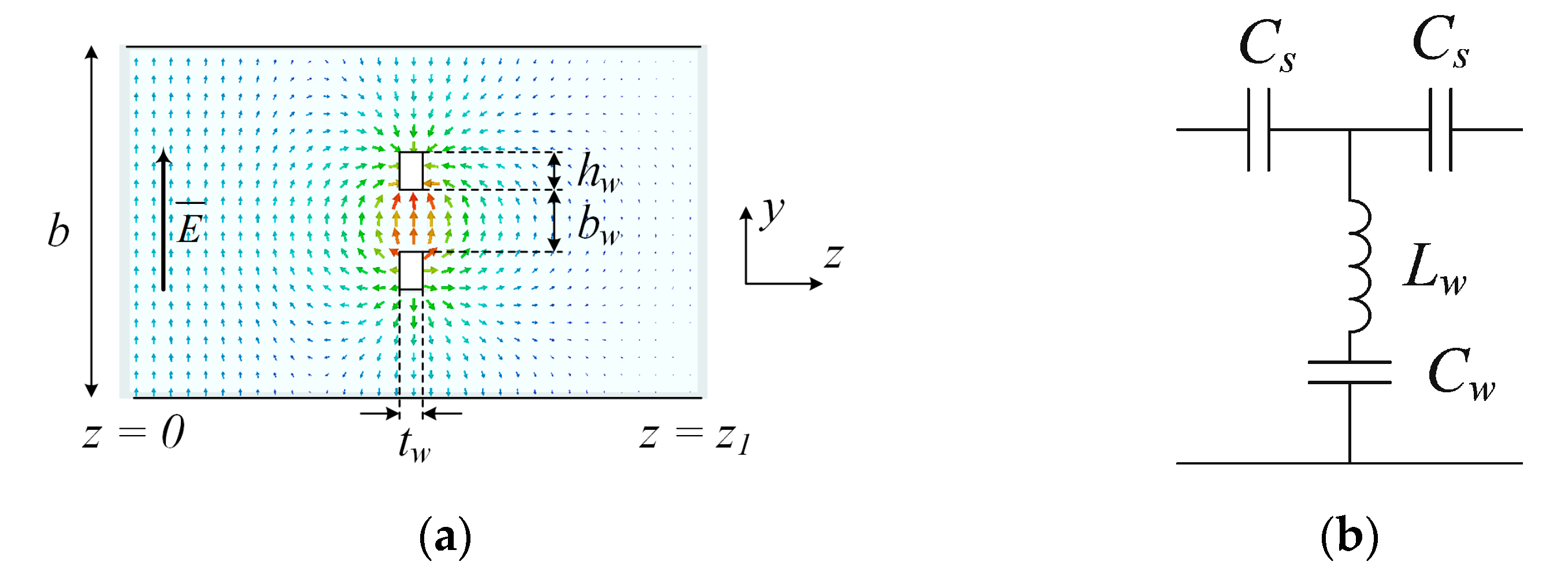
The simplified multi-aperture iris proposed in this work is depicted in Figure 2 Unlike the multi-aperture iris configurations analyzed in, for example, [20], the simplified version of Figure 2 introduces a single transmission zero at fz within the mono-mode waveguide bandwidth (fc < f < 2 fc), where fc is the TE10 cut-off frequency. This transmission zero is originated by a TEM resonance characterized by a TEM-like E-field distribution in the aperture [19]. The field distribution along the yz plane together with the corresponding electrical iris model is presented in Figure 3 In this scheme, series capacitors Cs have been introduced in order to account for the effect of the iris thickness, tw. When dealing with thin irises having tw < λg/50, these additional reactances could be omitted.
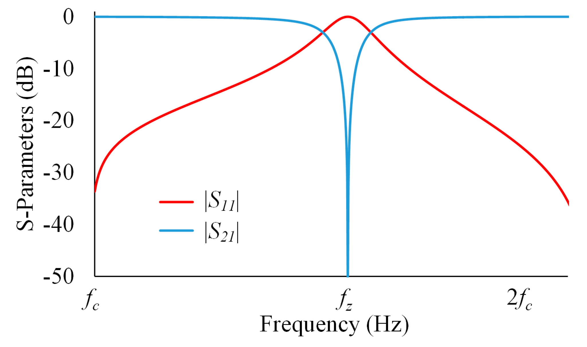
The behavior of the iris, at its natural resonance fz, can be qualitatively described with the help of Figure 3a. Within its mono-mode bandwidth, the input rectangular waveguide propagates the fundamental mode TE10, represented by E-field following y direction at z = 0. When this incident field reaches the iris, a TEM-like field distribution appears at the junction thus producing anti-phase components that cancel each other and creates the transmission zero at z = z1. Therefore, the scattering parameters of this structure, plotted in Figure 4, are those characteristic of a series resonant circuit following the configuration shown in Figure 3b.
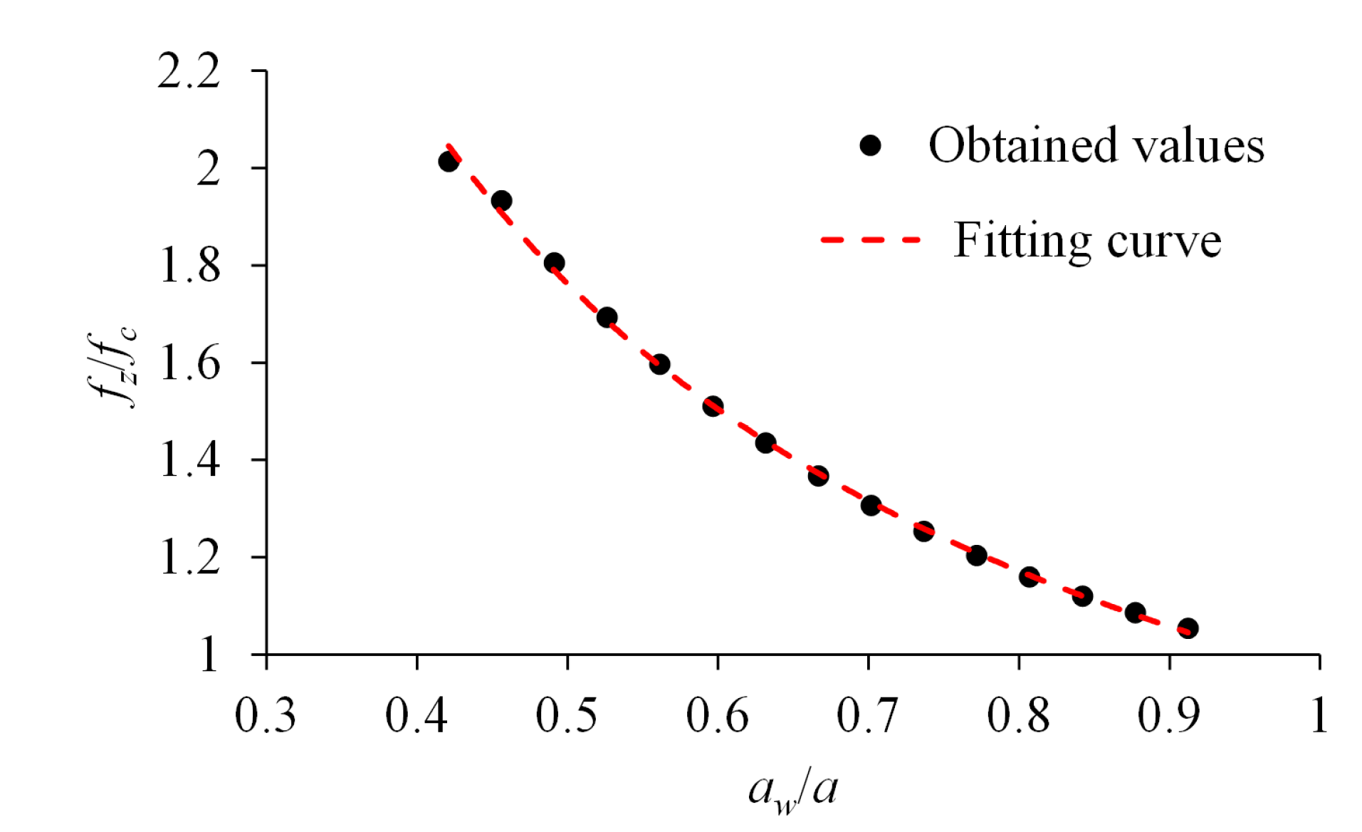
Iris dimensions, aw, bw and hw, have impact on the resonant frequency fz. Iris width, aw, is the main parameter that enables a total variation of the resonant frequency within the whole mono-mode waveguide bandwidth. For an exemplary structure in WR112 (a = 28.5 mm, b = 12.6 mm), with typical parameters bw = 2.14 mm, hw = 1.44 mm and tw = 1 mm (thin iris), the S-parameters are simulated as a function of the iris aperture aw and the extracted values of fz are plotted in Figure 5. Values of the resulting resonant frequencies can be fitted to a simple Equation (1).
( f z f c ) = k 1 ( a w a ) m 1
For the above exemplary geometry, the fitting parameters in (1), which are also included in Figure 5, are k1 = 0.9621 and m1 = 0.879. Practical limitations in dimension aw arise from the fact that when aw approaches a then there is no effective iris and the resonance disappears. On the other hand, for small values of aw, the resonance moves beyond the mono-mode bandwidth, which limits the circuit usefulness in filter designs.
An analogous procedure can be followed to analyze the effect of parameters bw and hw on the natural resonant frequency fz. These two parameters have less impact and they do not permit by themselves to produce a transmission zero sweeping the whole mono-mode bandwidth. Instead, a fine tuning of the frequency fz can be obtained. Moreover, the variation of fz with respect to these parameters follows a linear evolution for small ranges of values. Outside these ranges, which correspond to unpractical configurations, the resonant frequency has uneven behavior. The proposed fitting equations for parameters bw and hw are (2) and (3), respectively.
( f z f c ) = k 2 ( b w b ) + m 2
( f z f c ) = k 3 ( h w b ) + m 3
Using the common parameters values considered in the previous analysis and aw = 16.1 mm, then the unknowns in (2) are k2 = −0.6658 and m2 = 1.7036 for 0.08b < bw < 0.56b, while the unknowns in (3) are k3 = −0.6934 and m3 = 1.6664 for 0.04b < hw < 0.32b.
The last parameter that defines the iris dimensions in Figure 2, tw, has a minor effect on the resonant frequency, even for thick irises, and can be considered as negligible in this regard. However, the iris thickness, parameters bw and hw and the distance between consecutive irises, dsep, play an important role in the coupling mechanism between irises in a multi-section structure such as a high-selectivity filter. These parameters modify the interaction between resonant frequencies produced by different irises conforming the final filter response. Since the analysis of the multi-coupling effects based on these parameters is complex, final values are obtained through simple optimization, taking advantage of modern simulation tools that implement fast techniques such as mode matching. For this optimization, initial values for parameters aw, bw and hw are obtained with the help of (1)–(3). In the case of tw, a thin iris is advisable as long as mechanical limitations are fulfilled. Finally, dsep ~λg/10 is a good value as a starting guess for the design process. This reduced value of λg is the main responsible of the extreme compactness exhibited by this type of filters regarding other topologies that include λg/2 or λg/4 sections.

2.2. Receiver (Rx) Filter Design

The filter for the receiver chain is designed following a quasi-low-pass profile with a cut-off frequency of flp = 7.75 GHz. Obviously, there is no transmission below fc. The rejection requirement for this filter is |S21| < −90 dB at the edge frequency of the transmitting band, fhp = 7.9 GHz. Since this iris filter has an inherent band reject characteristic then a rejection bandwidth has to be defined. In this case, the rejection bandwidth covers the whole transmitting band (7.9–8.4 GHz).
The design philosophy relies on setting transmission zeros within the rejection bandwidth until the value of |S21| < −90 dB is obtained with the minimum number of sections, n. The resonant frequencies fzi, i = 1…p, are selected, in a first approximation, as equally distributed within this bandwidth. It is worth noting that the filter is a symmetric structure and consequently the number of different fz is p < n, as described in (4).
p = { n 2 ,   if   n   is   even f l o o r ( n 2 ) + 1 ,   if   n   is   odd
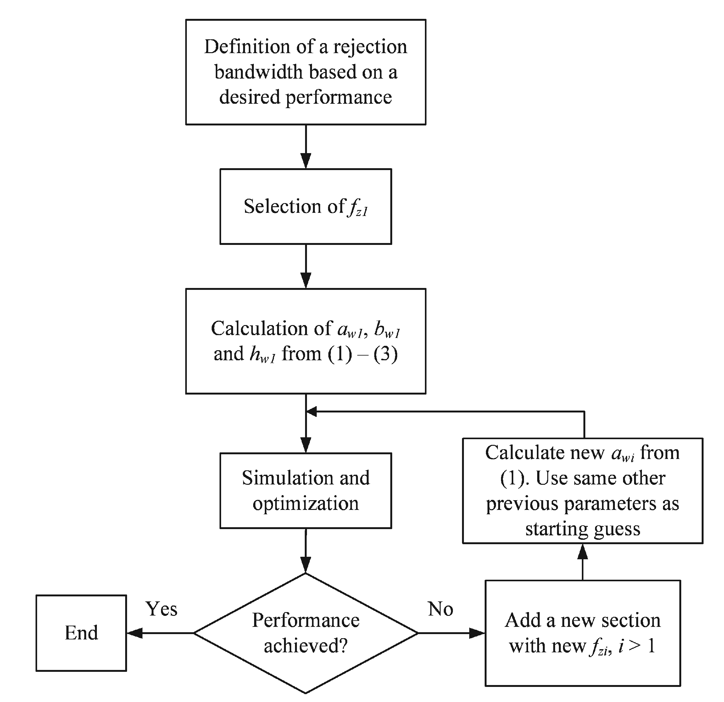
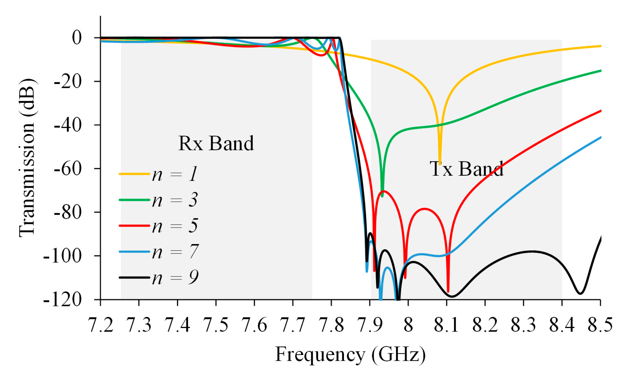
The iterative design procedure starts with the selection of fz1 and the calculation of the iris dimensions to accomplish this particular resonant frequency with the help of (1)–(3) for a given rectangular waveguide. If the final rejection requirement is not achieved, a new value of fz = fz2 is selected. The dimensions of the first iris serve as a starting point for this second iris but with a new aw value resulting from (1). Then parameters bw, hw, tw, dsep and aw are optimized to improve the coupling between irises while maintaining the desired transmission zeros. This procedure continues by adding filter sections until the desired |S21| rejection level is obtained. This strategy is schematically summarized in Figure 6 and its correlation with the transmission response, as the number of sections is increased, is clearly shown in Figure 7. The filter was designed in standard WR112 waveguide and the final dimensions are presented in Table 1. Simulation results have been obtained with the mode-matching electromagnetic simulation tool μWave Wizard from Mician.
As can be appreciated in Figure 7, a total number of n = 9 sections are needed for achieving 90 dB of rejection at 7.9 GHz, that is, an out-of-band rejection slope of 600 dB/GHz. This corresponds to p = 5 different transmission zeros fz that can be clearly distinguished. In Table 1, the different resonant frequencies for each iris as a single structure have been included. Therefore, the values of fz in Table 1 are not exactly those extracted form Figure 7 except for n = 1, which is obtained for the fifth iris, i = 5. This fifth iris represents the symmetry plane of the structure. Finally, simulated reflection of the complete filter is plotted in Figure 8 together with its transmission (same as in Figure 7) for completeness. From this figure, a reflection coefficient better of −25 dB can be observed in the full Rx band, 7.25–7.75 GHz. The total length of the designed filter is 60 mm excluding hollow waveguide accesses, which corresponds to around 1.5λg, being λg the waveguide wavelength at flp.
Additionally, a worst-case yield analysis was carried out to this filter in order to check the sensitivity of the proposed structure to mechanical tolerances. For this analysis, a standard tolerance value of ±20 μm for all the dimensions has been used. The results of this yield simulation provide maximum and minimum values for the filter’s transmission and reflection at each frequency. These two curves are included in Figure 8 with dashed lines and demonstrate that the proposed filter structure is robust enough against mechanical tolerances to fulfil the rejection requirement.

2.3. Transmitter (Tx) Filter Design

The filter in the transmitter path enables signal transmission in the 7.9–8.4 GHz frequency range while presents a rejection of |S21| < −90 dB in the receiver band. Consequently, although band-stop in nature, this filter follows a quasi-high-pass profile with a cut-off frequency of fhp = 7.9 GHz.
As it is widely known, band-pass and band-stop filters exhibit a less noticeable slope in transmission for frequencies above their defined bands with respect to the slope in the frequencies just below these bands. As a consequence, the transmitting filter requires a higher number of sections to accomplish the same level of rejection than the filter in the receiver band. With this important point in mind, the design strategy for this filter follows the same guidelines as in the Rx filter but in this case the transmission zeros are placed below the pass band. Due to the position of the resonant frequencies in the lower frequency range, iris dimensions and distances between consecutive irises, dsep, are larger than in the Rx filter. The achievement of the required rejection needs n = 11 sections for this filter, resulting in p = 6 different resonant frequencies. Due to the proximity of some of these frequencies, they are not clearly appreciated in Figure 9, where the final simulation results of this filter are presented. A return loss better than 25 dB in the Tx band is obtained whereas the rejection is better than 90 dB in the Rx band. The filter dimensions, obtained after a simple post-optimization process to get the desired transfer function, are presented in Table 2, where the values of fz are extracted from simulations of each individual iris. In this filter, the symmetry plane is located at the sixth iris. Finally, the total length of this filter is 105 mm, which is around 2λg, being λg the waveguide wavelength at fhp. Again, a yield analysis with the standard tolerance value of ±20 μm was performed and the results are presented in Figure 9 together with the nominal values.
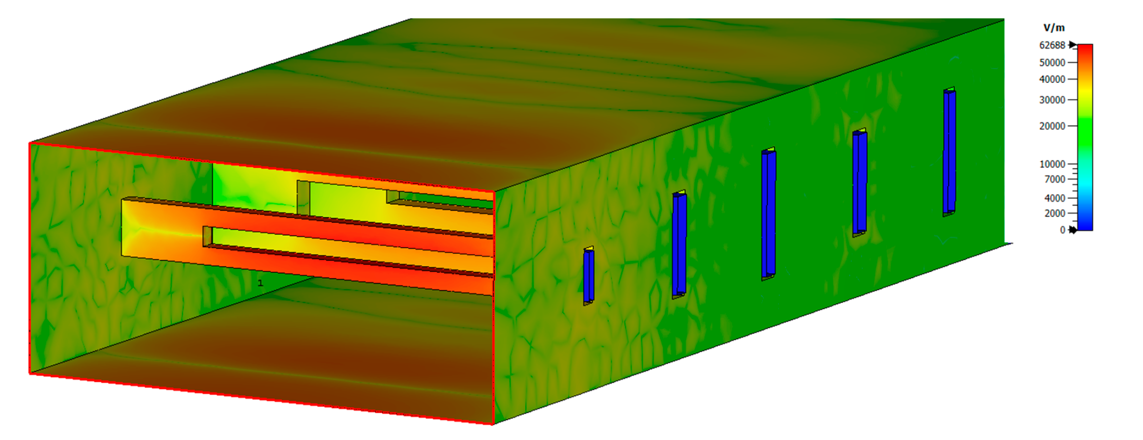
It is clear that the Tx filter represents the most limited structure in terms of power handling capabilities between the two designed filters for two reasons: it has the smallest bw value and the Tx band needs to withstand the transmitted power. Full 3D electromagnetic simulations with HFSS software have been carried out in order to obtain the maximum E-field value within this filter and thus to estimate the maximum power that the filter can handle. These simulations have shown a maximum value of electric field of around 6.3 × 10⁴ V/m at 7.75 GHz for an input power of 1 W as shown in Figure 10. Taking into account that the air breakdown E-field value at sea level is 3 × 10⁶ V/m, the maximum power that the filter can theoretically handle is near 2.3 kW. If a typical safety factor of 50% is considered, then it can be concluded that this filter can manage at least 1 kW, which should be enough for the intended application of SATCOMs. Regardless of this analysis, the iris gap (parameter bw) represents the most critical parameter in terms of power handling capability due to its small values that tend to concentrate the E-field. Therefore, power requirements for certain applications may impose a lower limit for this parameter, which could make it necessary to compensate this limitation, suitably modifying the other parameters within the structure.

3. Discussion on Filter Compactness

The ratio compactness/rejection slope is, without any doubt, the main strength of the proposed structure. It is difficult however to find appropriate filters in the literature to compare with, since the available configurations in these works are usually not intended for achieving such a high level of rejection.
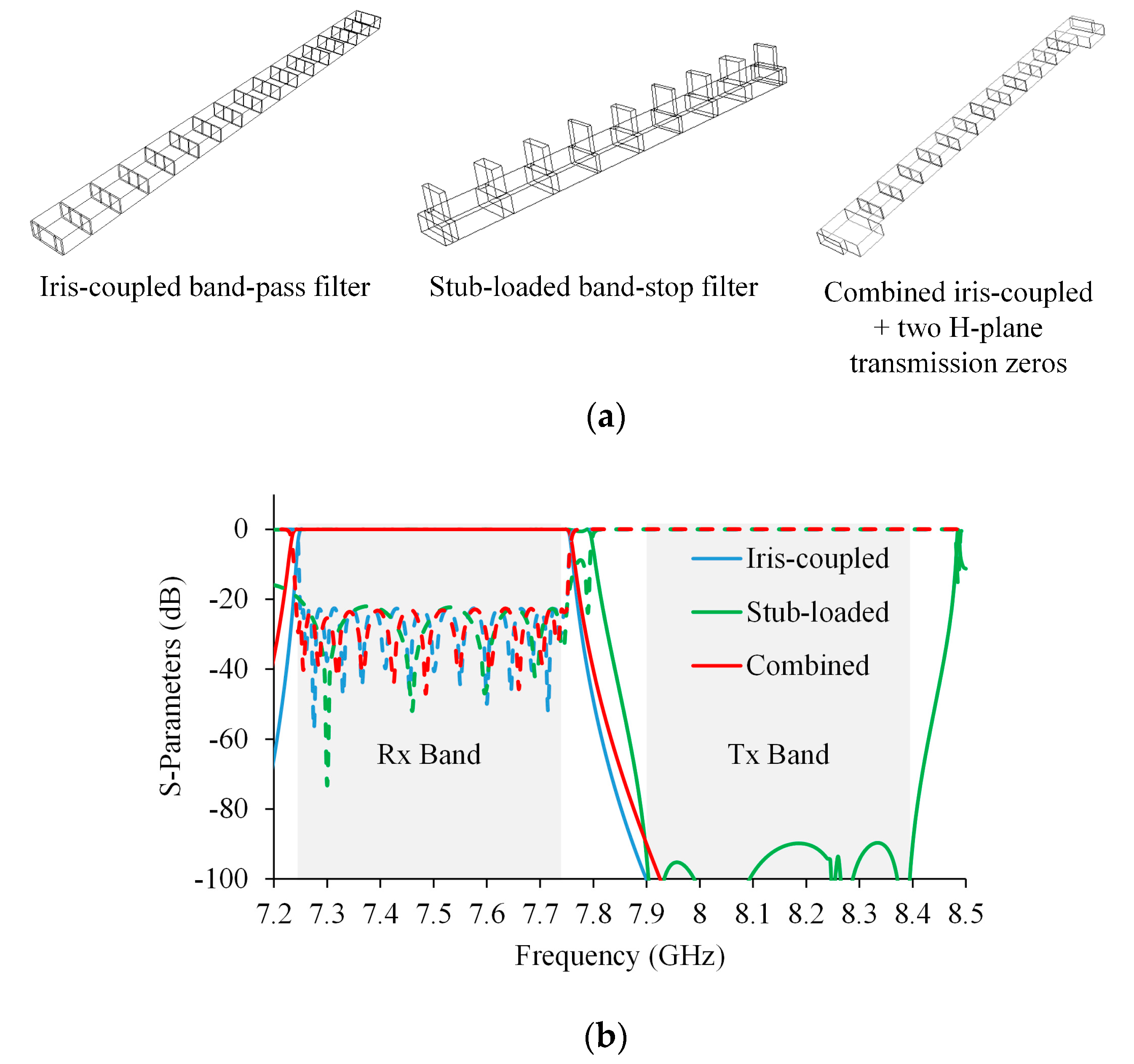
Consequently, the strategy followed to establish a fair comparison was based on the design of some different filters in the Rx band (7.25–7.75 GHz) aiming at a rejection of 90 dB at 7.9 GHz and using the common configurations that are utilized in the VSAT commercial filter solutions available worldwide. These configurations, schematically shown in Figure 11a, are the iris-coupled band-pass filter, the E-plane stub-loaded band-stop filter, and a classical combination of iris-coupled band-pass filter with H-plane transmission zeros. Simulated results of these three configurations are presented in Figure 11b. In the first case, the filter requires n = 16 sections with 17 irises and the total length is 420 mm. In the second configuration, the number of sections is n = 8 with a total of nine zeros introduced by the corresponding stubs, resulting in a total length of 320 mm. Finally, the third structure needs n = 11 sections and two additional zeros with a total length of 370 mm. Therefore, the filter topology introduced and analyzed in this work achieves an 86%, an 80% and an 84% size reduction respectively regarding those typical configurations.

4. Filter Manufacturing and Assembly

The proposed filters are designed in such a way that they can be easily divided into two metallic blocks by their E-field symmetry plane. Thus, the insertion loss is minimized which assures the best performance for the SATCOM terminal both in reception, by increasing the sensitivity, and in transmission, by maximizing the power efficiency. In Figure 12a, a sketch of half Rx filter is shown. This part is identical to the complementary part due to the structure symmetry and it is similar to the corresponding Tx filter. Two pictures of the manufactured Rx filter are shown in Figure 12b.
As can be appreciated in Figure 12, the mechanical design enables an easy manufacturing with standard numerically controlled milling techniques and suitable bits. Moreover, due to the simple iris configuration implemented in these filters, the stack of thin metallic sheets and/or rounded corners present in other configurations are avoided. Filter pieces are machined in aluminum. When the two pieces of each filter are finished, they are put together and tightly attached with screws. In order to get a further improvement in the insertion loss, both filters were silver plated.

5. Filter Characterization and Results

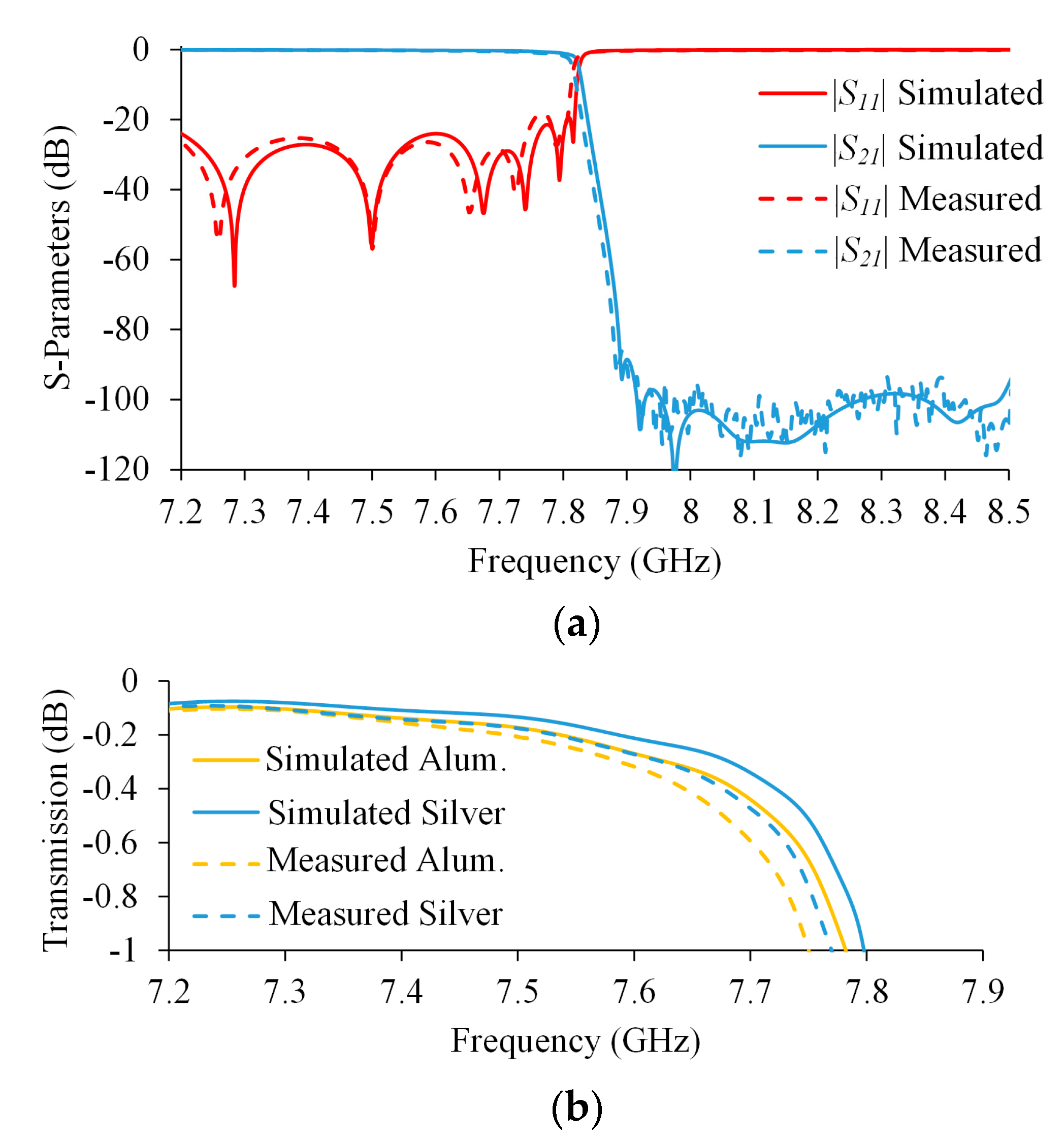
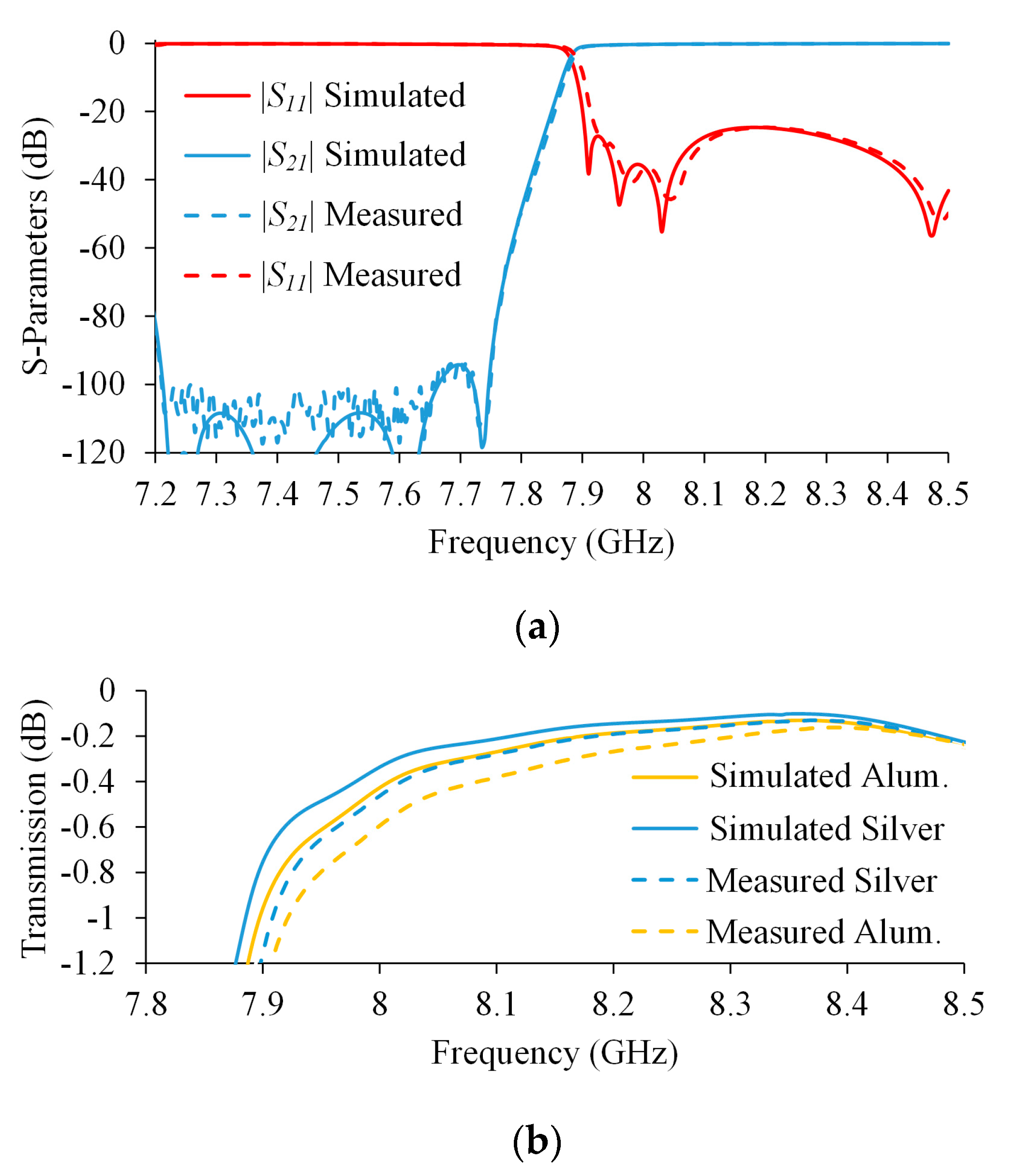
Filters characterization was carried out using a vector network analyzer N5227A from Keysight Technologies connected to commercial coaxial-to-WR112 transitions. The thru-reflect-line (TRL) calibration technique was applied at the WR112 accesses so the calibration planes are effectively established at these waveguide ports. Consequently, the measured data correspond to the filters only, without any additional hardware. Results from these measurements are plotted in Figure 13 and Figure 14 for the Rx and Tx filters, respectively. Additionally, in these figures, full wave simulation results taking into account the electrical conductivity of aluminum and silver, σAl = 3.7 × 10⁷ S/m and σAg = 6.3 × 10⁷ S/m respectively, have been included for a better comparison. The corresponding simulation results have been obtained using the 3DFEM capability of μWave Wizard.
Measured results of the filters after silver plating, also present in Figure 13 and Figure 14, confirm simulations and design strategy. For the Rx filter, the measured reflection coefficient is better than −25 dB in the band of interest whereas the transmission coefficient drops to −90 dB at 7.9 GHz, where the Tx band starts. A detailed inspection of the insertion loss plotted in Figure 13b, demonstrates that these values are better than 1 dB in all the cases. As expected, silver plating improves the insertion loss and measured values are higher than the simulated ones due to the different electrical conductivities of real materials and the effect of material roughness, which is not taken into account during simulations. The insertion loss mean value in the 7.25–7.75 GHz band for the silver-plated Rx filter is 0.24 dB.
With respect to the fabricated Tx filter, with results shown in Figure 14, again the reflection is better than -25 dB in the frequency range of interest with a rejection level of -90 dB or better at the edge of the Rx band. As could be expected from a longer design working at higher frequencies, the filter insertion loss with aluminum finishing is above 1 dB at the lower end of the band. However, when the silver-plated finishing is applied, this insertion loss is reduced accordingly and it is kept within limits. The insertion loss mean value in the 7.9–8.4 GHz band for the silver-plated Tx filter is 0.38 dB.
Finally, Table 3 shows a comparison between the filters proposed in this work and other related structures found in the literature.

6. Conclusions

The suitability of a simplified version of multi-aperture iris for the design of high-performance filters in SATCOM terminals has been analyzed and validated in this work. This iris topology provides an adequate flexibility for accomplishing stringent requirements through the placement of a transmission zero at a desired frequency through an easy control of the physical dimensions. This strategy implies a drastic 80% reduction in the size of the filters and, therefore, a much more compact terminal could be developed. This compactness feature, together with the excellent rejection slopes achieved by cascading transmission zeros, enables to obtain a record in the size/rejection ratio regarding other filters topologies analyzed in the available literature. Moreover, the proposed iris configuration presents some advantages from the mechanical point of view such as an easy mechanization and its suitability for being divided by the E-field symmetry plane, which minimizes insertion loss regarding classical implementations with stacked metallic thin layers. Two filters covering the Rx (7.25–7.75 GHz) and Tx (7.9–8.4 GHz) sub-bands in standard X-band SATCOM applications have been demonstrated showing excellent electrical performance with 25 dB of return loss, an insertion loss better than 1 dB at the band edges, and a minimum of 90 dB out-of-band rejection. It was not possible to show the filter performances when embedded in a SATCOM terminal because authors do not have access to the measurements of the complete commercial system.

Author Contributions

Conceptualization, J.L.C., and A.M.; Funding acquisition, A.M.; Investigation, J.L.C., A.M. and A.T.; Supervision, A.M.; Validation, J.L.C. and A.T.; Writing—original draft, J.L.C.; Writing—review & editing, A.M. and A.T. All authors have read and agreed to the published version of the manuscript.

Funding

This work was supported by the State Research Agency, Spanish Ministry of Economy, Industry and Competitiveness, through project TEC2017-83343-C4-1-R and FEDER funds from the EU.

Conflicts of Interest

The authors declare no conflict of interest. The funders had no role in the design of the study; in the collection, analyses, or interpretation of data; in the writing of the manuscript, or in the decision to publish the results.

References

  1. Miyazaki, M.; Yukawa, H.; Nishino, T.; Urasaki, S.; Katagi, T. Design of iris-coupled broadband waveguide filter using modified reflection-zero frequencies. Electron. Commun. Jpn. 2000, 83, 59–67. [Google Scholar] [CrossRef]
  2. Kocbach, J.; Folgerø, K. Design procedure for waveguide filters with cross-couplings. In Proceedings of the 2002 IEEE MTT-S International Microwave Symposium Digest, Seattle, WA, USA, 2–7 June 2002; pp. 1449–1452. [Google Scholar]
  3. Morro, J.V.; Pacheco, P.S.; Gonzalez, H.E.; Esbert, V.B.; Martín, C.B.; Calduch, M.T.; Borrás, S.C.; Martínez, B.G. Fast automated design of waveguide filters using agressive space mapping with a new segmentation strategy and a hybrid optimization algorithm. IEEE Microw. Theory Tech. 2005, 53, 1130–1142. [Google Scholar]
  4. Leal-Sevillano, C.A.; Pisano, G.; Montejo-Garai, J.R.; Maffei, B.; Ruiz-Cruz, J.A.; Ng, M.W.; Rebollar, J.M. Development of low loss waveguide filters for radio-astronomy applications. Infrared Phys. Tech. 2013, 61, 224–229. [Google Scholar] [CrossRef]
  5. Amari, S.; Rosenberg, U. Synthesis and design of novel in-line filters with one or two real transmission zeros. IEEE Trans. Microw. Theory Tech. 2004, 52, 1464–1478. [Google Scholar] [CrossRef]
  6. Zhang, Q.; Lu, Y. Design of wide-band pseudo-elliptic waveguide filters with cavity-backed inverters. IEEE Microw. Wirel. Comp. Lett. 2010, 20, 604–606. [Google Scholar] [CrossRef]
  7. Carceller, C.; Soto, P.; Boria, V.; Guglielmi, M. Capacitive obstacle realizing multiple transmission zeros for in-line rectangular waveguide filters. IEEE Microw. Wirel. Comp. Lett. 2016, 26, 795–797. [Google Scholar] [CrossRef] [Green Version]
  8. El Sabbagh, M.; Zaki, K.A.; Yao, H.-W.; Yu, M. Full-wave analysis of coupling between combline resonators and its application to combline filters with canonical configurations. IEEE Trans. Microw. Theory Tech. 2001, 49, 2384–2393. [Google Scholar] [CrossRef]
  9. Levy, R.; Snyder, R.V.; Matthaei, G. Design of microwave filters. IEEE Trans. Microw. Theory Tech. 2002, 50, 783–793. [Google Scholar] [CrossRef] [Green Version]
  10. Subramanyam, A.V.G.; Siva Reddy, D.; Hariharan, V.K.; Srinivasan, V.V.; Chakrabarty, A. High power combline filter for deep space applications. Int. J. Microw. Sci. Tech. 2014, 2014, 396494. [Google Scholar] [CrossRef]
  11. Levy, R. Tapered corrugated waveguide low-pass filters. IEEE Trans. Microw. Theory Tech. 1973, 21, 526–532. [Google Scholar] [CrossRef]
  12. Xu, Z.B.; Guo, J.; Quian, C.; Dou, W.B. A novel miniature transmit reject filter for Ku-band VSAT transceivers. In Proceedings of the 2008 IEEE MTT-S International Microwave Workshop Series on Art of Miniaturizing RF and Microwave Passive Components, Chengdu, China, 14–15 December 2008; pp. 113–115. [Google Scholar]
  13. Teberino, F.; Arregui, I.; Soto, P.; Laso, M.A.G.; Boria, V.E.; Guglielmi, M. High-performance compact diplexers for Ku/K-band satellite applications. IEEE Trans. Microw. Theory Tech. 2017, 65, 3866–3876. [Google Scholar] [CrossRef]
  14. Bastioli, S.; Marcaccioli, L.; Sorrentino, R. Waveguide pseudoelliptic filters using slant and transverse rectangular ridge resonators. IEEE Trans. Microw. Theory Tech. 2008, 56, 3129–3136. [Google Scholar] [CrossRef]
  15. Rosenberg, U.; Amari, S. A novel band-reject element for pseudoelliptic bandstop filters. IEEE Trans. Microw. Theory Tech. 2007, 55, 742–746. [Google Scholar] [CrossRef]
  16. Barrio-Garrido, R.M.; Llorente-Romano, S.; Salazar-Palma, M. Design of Ka band highly selective wideband band-pass filters using directly coupled resonant irises. In Proceedings of the IEEE Antennas and Propagation Society International Symposium. Digest. Held in conjunction with: USNC/CNC/URSI North American Radio Sci. Meeting, Columbus, OH, USA, 22–27 June 2003; pp. 1161–1164. [Google Scholar]
  17. Barrio-Garrido, R.M.; Llorente-Romano, S.; Salazar-Palma, M.; Oñoro-Navarro, A.; Hidalgo-Carpintero, I. Design, construction and experimental characterization of a broadband highly selective filter in waveguide technology in Ka band. In Proceedings of the 2006 IEEE MTT-S International Microwave Symposium Digest, San Francisco, CA, USA, 11–16 June 2006; pp. 250–253. [Google Scholar]
  18. Yang, R.; Omar, A.S. Investigation of multiple rectangular aperture irises in rectangular waveguide using TExmn-modes. IEEE Trans. Microw. Theory Tech. 1993, 41, 1369–1374. [Google Scholar] [CrossRef]
  19. Kirilenko, A.A.; Mos’pan, L.P. Reflection resonances of two-aperture irises in rectangular waveguide. In Proceedings of the 29th European Microwave Conference, Munich, Germany, 5–7 October 1999; pp. 28–31. [Google Scholar]
  20. Leal-Sevillano, C.A.; Montejo-Garai, J.R.; Ruiz-Cruz, J.A.; Rebollar, J.M. Wideband equivalent circuit for multi-aperture multi-resonant waveguide irises. IEEE Trans. Microw. Theory Tech. 2016, 64, 724–732. [Google Scholar] [CrossRef]
  21. Rodriguez-Berral, R.; Mesa, F.; Medina, F. Resonant modes of a waveguide iris discontinuity: Interpretation in terms of canonical circuits. IEEE Trans. Microw. Theory Tech. 2018, 66, 2059–2069. [Google Scholar] [CrossRef]
  22. Tsuji, M.; Deguchi, H. A new frequency selective window for constructing waveguide bandpass filters with multiple attenuation poles. Prog. Electromagn. Res. 2011, 20, 139–153. [Google Scholar] [CrossRef] [Green Version]
  23. Zhang, Y.; Meng, H.; Wu, K. Synthesis of microwave filters with dispersive coupling using isospectral flow method. In Proceedings of the 2019 IEEE MTT-S International Microwave Symposium (IMS), Boston, MA, USA, 2–7 June 2019; pp. 846–848. [Google Scholar]
  24. Zhang, Y.; Meng, H.; Wu, K. Direct synthesis and design of dispersive waveguide bandpass filters. IEEE Trans. Microw. Theory Tech. 2020, 68, 1678–1687. [Google Scholar] [CrossRef]
  25. Marcuvitz, N. Waveguide Handbook; McGraw-Hill: New York, NY, USA, 1951; pp. 217–335. [Google Scholar]
  26. Rizzi, P.A. Microwave Engineering: Passive Circuits; Prentice-hall Int.: Upper Saddle River, NJ, USA, 1988; pp. 299–346. [Google Scholar]
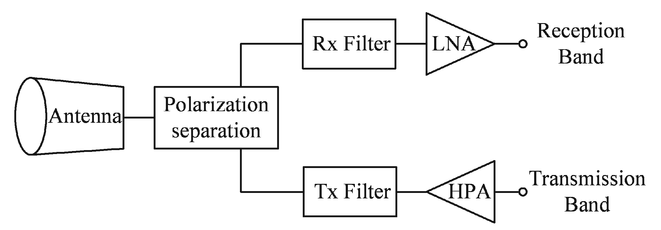
Figure 1. Electrical scheme of the antenna feed network in a typical SATCOM single-band terminal.
Electronics 09 01221 g001
Figure 2. Simplified multi-aperture iris with definition of dimensions.
Electronics 09 01221 g002
Figure 3. E-field simulation and electrical model of the analyzed generic iris: (a) Field distribution along yz plane, (b) electrical model for a thick iris.
Electronics 09 01221 g003
Figure 4. Simulated S-parameters results for a generic simplified multi-aperture iris.
Electronics 09 01221 g004
Figure 5. Simulated resonant frequency fz variation as a function of the iris width aw.
Electronics 09 01221 g005
Figure 6. Summary of the filter synthesis procedure.
Electronics 09 01221 g006
Figure 7. Simulated transmission |S21| variation as a function of the number of filter sections.
Electronics 09 01221 g007
Figure 8. Simulated results of the designed Rx band filter with dimension from Table 1. Magnitude of S11 is plotted with red color whereas magnitude of S21 is plotted with blue color. Solid lines correspond to nominal values and dashed lines limit the maximum and minimum values obtained after performing a yield analysis with ±20 μm standard tolerance.
Electronics 09 01221 g008
Figure 9. Simulated results of the designed Tx band filter with dimension from Table 2. Magnitude of S11 is plotted with red color whereas magnitude of S21 is plotted with blue color. Solid lines correspond to nominal values and dashed lines limit the maximum and minimum values obtained after performing a yield analysis with ±20 μm standard tolerance.
Electronics 09 01221 g009
Figure 10. Simulated results of the maximum E-field in the Tx filter at 7.75 GHz. Maximum value of 62.688 V/m is obtained at the first iris.
Electronics 09 01221 g010
Figure 11. (a) Designed filter topologies for size comparisons with the proposed structure in the VSAT Rx band, (b) simulated transmission (solid lines) and reflection (dashed lines) results of the designed topologies.
Electronics 09 01221 g011
Figure 12. Mechanical design and manufactured Rx filter. (a) Sketch of half Rx filter, (b) pictures of the manufactured Rx filter before silver plating.
Electronics 09 01221 g012
Figure 13. Comparison between measured and simulated results of the Rx filter. (a) Full scale reflection and transmission for the silver-plated version, (b) zoomed transmission in the band of interest.
Electronics 09 01221 g013
Figure 14. Comparison between measured and simulated results of the Tx filter. (a) Full scale reflection and transmission for the silver-plated version, (b) zoomed transmission in the band of interest.
Electronics 09 01221 g014
Table 1. Rx band filter dimensions.
iaw
(mm)
bw
(mm)
tw
(mm)
hw
(mm)
dsep
(mm)
fz
(GHz)
116.102.142.431.446.108.50
216.022.621.062.144.368.05
316.003.042.312.315.208.16
416.043.021.191.195.698.03
516.003.021.451.45-8.08
Table 2. Tx band filter dimensions.
iaw
(mm)
bw
(mm)
tw
(mm)
hw
(mm)
dsep
(mm)
fz
(GHz)
118.361.130.970.989.047.74
217.922.881.361.468.747.42
318.053.001.382.089.037.21
417.502.391.411.739.057.64
518.063.051.242.008.907.19
617.383.001.492.00-7.47
Table 3. Comparison between performances of proposed filters and other related works found in the literature.
Ref.Frequency
Range
(GHz)
Rejection
Slope
(dB/GHz)
Number
Sections
Return
Loss
(dB)
Insertion
Loss
(dB)
Length
g)
[17]27.2–30.737921-~3.25
[16]~27–30.522725-~2
[4]85–1051510150.44
[12]11–13.5705120.31.3
[6]9.51–10.6425420-~2.4
[14]10.1–10.42203200.351.42
This work (Rx)7.25–7.756009250.241.5
This work (Tx)7.9–8.460011250.382