Abstract
A novel fractal-based metamaterial unit cell, useful for ambient power harvesting, is proposed to operate within the 2.45 GHz Wi-Fi band. The simulated fractal cell offers very high absorption coefficients, a wide-angle and polarization-insensitive behavior, and very small size. A 9 × 9 fractal-based metamaterial harvester is designed and simulated, by demonstrating a very high harvesting efficiency equal to 96.5% at 2.45 GHz. The proposed metamaterial configuration could be very appealing for the implementation of high efficiencies and compact harvesting systems for wireless sensor network applications.
1. Introduction
The explosive growth of the wireless communication industry has led to a dramatic increase in the energy cost. In order to enable the emerging Internet-of-Things (IoT), future wireless communications networks are expected to incorporate densely distributed base stations serving a huge number of low-power wireless devices. At the same time, wireless sensor networks (WSNs) applications will become increasingly widespread and pervasive in our daily lives. WSN technology is nowadays applied to an ever increasing number of environmental [1], industrial, and consumer applications, such as manufacturing process monitoring and control, home automation and security [2], health monitoring [3], object tracking applications [4], etc. One of the major challenges facing WSNs is related to the limited and non-renewable energy supply of the sensor nodes. As a matter of fact, they usually operate on conventional batteries with a limited lifespan and fixed energy rate. Furthermore, the deployment of a large number of sensor nodes results in periodic battery replacement, which is impractical and cost-consumed [5]. A promising solution to overcome the above issues could be the adoption of energy-harvesting systems [6].
In the last decade, energy-harvesting technology has attracted huge attention, due to its ability to produce electricity from various environmentally friendly energy sources, such as solar, wind, motion, vibration, and radio frequency (RF). Due to the increasing availability of free RF energy, radio frequency energy harvesting [7] is very attractive for wireless sensor networks (WSNs) applications and low-power devices for consumer electronics. As a matter of fact, ambient RF energy could be provided by several RF broadcasting infrastructures, such as analog/digital TV, AM/FM radio, and GSM and Wi-Fi networks. Usually, an RF-harvesting system consists of a rectifying antenna, namely a rectenna, which is able to harvest high-frequency energy in free space and convert it to DC power [7]. Rectennas, originally introduced in 1960s [8], typically comprise a receiving antenna and a rectifying circuit, namely a combination of a matching network/bandpass filter, one or more rectifying diodes, and a low-pass filter [9].
The antenna is the key element of an RF-energy harvesting system, able to efficiently capture and convert the incident RF energy into AC power, by conveying it to the rectifier input for the AC-to-DC power conversion.
Until today, several antenna topologies have been designed for RF energy harvesting [9,10,11,12]. Antennas adopted in conventional rectenna-based harvesters offer a very simple integration with the most rectifier circuits in the literature [9,10,11,12], also producing high harvesting efficiencies [9] in the overall conversion path from RF-to-DC power. However, the amount of energy collected by a single antenna is relatively small and useful only for very-low-power applications [11,12]. In order to achieve greater amounts of harvested power, the use of rectennas in array form is recommended [13,14,15,16,17,18], as the contribution of each individual cell is constructively added.
To this end, metasurface (or metamaterial) structures have been recently proposed as a promising alternative to conventional rectennas, with the key advantage of greater amounts of harvested power and higher efficiencies in the preliminary conversion stage from RF-to-AC power [13,14,15,16,17,18,19,20,21]. A metamaterial harvester comprises an array of electrically small resonators, printed on a grounded dielectric substrate. Similarly to metamaterial absorbers, each resonator effectively couples to the incident electromagnetic (EM) wave, at the resonance, thus capturing the EM power from the ambient. However, while metamaterial absorbers dissipate the collected EM power within their structure, either as ohmic or dielectric losses, in the case of metamaterial harvesters, the energy captured by each resonator is channeled through one or more vias to a feeding network [15,17] which collects the AC power and feeds it to rectification circuitry for the next AC-to-DC conversion stage. Without loss of generality, a metamaterial harvester can be designed to achieve outstanding performance in terms of absorption efficiency, by modeling the input impedance of each branch of the feeding network and/or the rectifier circuit with a grounded resistive load.
Several metamaterial cells for energy harvesting have been recently investigated in the literature. In particular, Ramahi et al. gave a significant contribution in the development of different metamaterial harvester configurations [13,14,15,16,17,18].
A unit cell based on the use of a split ring resonator (SRR) is tested in [13,14] to operate around 5.8 GHz. A metasurface, based on the use of electrical cross-resonators, with a corporate feed network to channel the collected AC energy into a single rectification circuit, is designed in [15] by showing an RF-to-AC efficiency of 92% at 2.9 GHz. A dual-band electromagnetic energy harvester, comprising an array of pixelated unit cells, is proposed in [16] to resonate at 2.45 and 6 GHz, offering a 90% RF-to-AC efficiency. A dual-polarized electromagnetic energy harvester is proposed in [17] for operation at 2.4 GHz; it has two distinct corporate feed networks, one for each polarization, adopted to channel the collected AC into two distinct rectifier circuits. A polarization-independent cross-dipole harvesting surface with an RF-to-AC efficiency equal to 94% at 3 GHz is proposed in [18]. In this last design, both the rectification from AC-to-DC, as well as the DC channeling, are hosted on the same plane of the elements. A metamaterial device, consisting of four identical omega ring resonators arranged in rotational symmetry, is proposed in [19] to operate at 5.8 GHz, offering an efficiency up to 93.1%, under normal incidence. A low-cost air gap metasurface structure is illustrated and discussed in [20] to resonate around 2.45 GHz with an RF-to-AC efficiency of about 85.9%.
Despite the great efforts given in the last decade on the metamaterial harvester systems research area, several open challenges still exist in the design and the practical implementation of metamaterial harvesters, which affect the effectiveness of the overall RF–DC conversion process. They are mainly related to the following tasks: (a) Design of a perfect absorbing metasurface, quite independent of the polarization and/or the direction of the impinging EM signal, able to realize an efficient RF-to-AC conversion stage; (b) optimization of a feeding network, maximizing the power transfer to the input ports of the rectification circuitries; (c) optimization of this last circuit block, necessary for realizing an efficient AC–DC conversion stage. The last two points could be merged together based on the adopted strategy for signal rectification and channeling (i.e., AC power channeling from the array elements to a single rectification circuit for the AC-to-DC conversion stage [15]; multiple AC-to-DC rectifiers, one for each array element, and DC channeling [18]).
With respect to the aforementioned task (a), in order to offer an appealing alternative to the existing solutions in the literature, a polarization-independent metamaterial energy harvester is proposed in this work, which is able to offer very high RF-to-AC efficiency values for different directions of the impinging wave, thinner profiles, and smaller unit cell sizes.
The unit cell basically consists of a miniaturized Minkowski fractal element printed on a thin grounded dielectric substrate, loaded by two resistive loads modeling the rectification circuitry. The fractal geometry, already adopted by the authors for reflectarray design [22,23], as well as for the realization of metamaterial absorbers able to reduce the multipath in UHF-RFID systems [24,25], allows us to achieve very small unit cells with respect to standard geometries. Furthermore, as demonstrated in [25,26], the adopted fractal patches can be fruitfully exploited to obtain multiband operation skills.
The cell is designed to offer full absorption of the incoming wave at the resonance frequency equal to 2.45 GHz. Furthermore, in order to maximize the RF–AC efficiency of the cell, the structure is properly designed to concentrate the losses within the loads, rather than into the substrate material and/or the copper. As a consequence of this, the captured energy will be available at the terminals of the diodes or the rectification circuitries necessary for AC-to-DC power conversion. The latter circuit block is not currently the topic of our work; it will be the subject of future developments for a comprehensive experimental validation of the proposed solution.
A preliminary analysis of the proposed fractal-based harvester is presented and discussed in the following
s. Good miniaturization capabilities, very high absorption percentages, good angular stability, and very high polarization independence, with respect to other existing configurations are demonstrated in correspondence to the LTE/Wi-Fi frequency (i.e., 2.45 GHz). Furthermore, a thorough analysis of the proposed unit cell performances in terms of RF-to-AC energy efficiency is presented, showing very high and polarization-insensitive efficiency values.
2. Unit Cell Layout and Design
The proposed metamaterial configuration for ambient power harvesting applications is depicted in Figure 1. It consists of a periodic pattern of identical unit cells printed on a very thin grounded dielectric slab. Each cell comprises a metallic Minkowski fractal patch loaded by two resistive loads, which model the downstream rectification circuitry. Two vias are used to efficiently channel the collected EM energy to the resistor loads Rx and Ry (Figure 1).
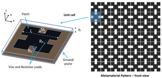
Figure 1.
Metamaterial unit cell for ambient power harvesting.
The proposed fractal shape is synthesized for perfect absorption, namely to perform the matching between unit cell and free space impedances at a given resonant frequency f0, namely Zcell (f0) = ζ0 =. As thoroughly discussed in [16], both degrees of freedom inherent to the adopted Minkowski shape, i.e., the patch length L and the inset size SL (Figure 1), are properly exploited to satisfy the above condition. Furthermore, both via positions, as well as the resistive value of the two loads, are properly chosen to satisfy the following goals:
- Maximize the percentage rate of the absorbed RF energy;
- Assure a polarization-insensitive behavior with respect to the impinging electromagnetic signal.
The Minkowski fractal shape, already adopted by the authors in [24], for designing a UHF metamaterial absorber, consists of a modified L × L square element with a SL × SL square inset at the center of each sides. S is the scaling factor, varying from 0 up to 1/3. As it is well known, the above fractal shape allows an electrically longer resonator to fit into a smaller unit cell [22,23], thus offering very exciting miniaturization skills. As a matter of fact, the effective side length of the patch, approximately equal to Leff = (1 + 2S) L [24], is inversely proportional to the patch resonance frequency (i.e., f0 ~ 1/Leff). For this reason, the combined use of a smaller patch length L and a greater S-value allows us to move down the resonant frequency f0, keeping a reduced footprint.
Following the design rules outlined in [22], a miniaturized 0.123λ × 0.123λ cell is designed to operate at the central frequency f0 = 2.45 GHz. To minimize dielectric losses, a Rogers TMM10 dielectric substrate is considered, having a loss tangent equal to 0.002, a dielectric constant εr = 9.8, and a thickness h = 1.524 mm. The resistive loads are assumed to be equal to Rx = Ry = R = 50 Ω, while the sizes of the Minkowski patch are properly fixed to the following values: L = 14.5 mm and S = 0.245.
The proposed metamaterial structure is backed by a metallic sheet (i.e., the ground plane in Figure 1), so there is no transmission through the absorber panel, and we only need the metamaterial reflection response (i.e., Г parameter) to correctly evaluate the absorptivity (i.e., A = 1 − |Г|2) of the proposed structure. A commercial full-wave code (Ansys), based on the infinite array approach, is adopted, assuming a normally incident plane wave. As demonstrated in Figure 2, an absorption peak equal to about 99% is obtained at 2.45 GHz (see the absorption coefficient A(f) in Figure 2a), due to the perfect matching between the unit cell and the free space, achieved in a neighborhood of the same frequency (see the normalized unit cell impedance Zcell(f) in Figure 2b).
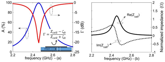
Figure 2.
Unit cell loaded by two 50 Ω resistors: (a) Absorption (blue line) and reflection (red line) coefficients vs. frequency; (b) normalized cell impedance (i.e., Zcell) vs. frequency.
In order to appreciate the effect of the resistors load Rx and Ry, namely the input impedance of the rectification circuitry necessary for the AC-to-DC conversion stage, Figure 3 depicts the unit cell behavior for different loading conditions. It can be observed how the same metallic resonator (L = 14.5 mm and S = 0.245), without any vias and resistor loads, does not satisfy the perfect absorption condition (see the black line in Figure 3), offering an absorption rate of just 20%, due to the high mismatching obtained between free space and unit cell impedances (Zcell ≅ 2.9 kΩ @2.45 GHz). Conversely, by inserting the via connections to the resistor loads, the unit cell impedance Zcell decreases. In particular, by reducing the resistance values, R, from 200 (Figure 3) down to 50 Ω (Figure 2), the real part of the unit cell impedance Zcell gradually approaches the free space value ζ0, in correspondence to f0 = 2.45 GHz (see the proposed test case already illustrated in Figure 2), thus assuring a very good absorption of the impinging electromagnetic wave. Therefore, both the patch sizes, as well as the resistive loads, must be optimized in order to achieve the best absorption efficiency.
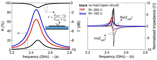
Figure 3.
Unit cell loaded by different resistive loads (i.e., R): (a) Absorption and reflection coefficients vs. frequency; (b) normalized cell impedance vs. frequency.
As a further analysis, a good angular stability is demonstrated for both TE (Figure 4a) and TM (Figure 4b) polarizations. To this end, the absorption coefficients vs. frequency are computed for different incidence angles θinc, showing very high peak values (≥96%), for both TE and TM polarizations (φinc = 0°). Finally, Figure 5 shows the polarization-insensitive behavior of the proposed metamaterial absorber cell. As a matter of the fact, a quite good and stable absorption rate is achieved vs. the φinc angle variations, both for the normal incidence (≥96% when θinc = 0°), as well as for the oblique incidence case, namely for θinc varying up to 60° (≥88% for TE-polarization and ≥80% for TM-polarization).
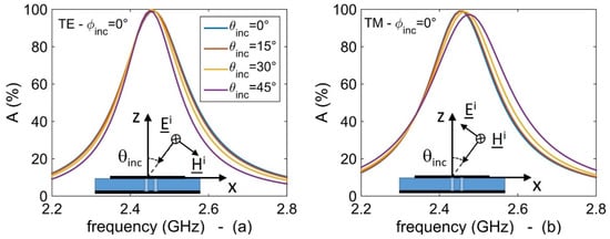
Figure 4.
Absorptivity vs. frequency of the synthesized metamaterial harvester for different incidence angles: (a) TE-polarization; (b) TM-polarization.
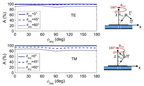
Figure 5.
Absorptivity of the synthesized metamaterial harvester vs. polarization angle φinc for different oblique incidence angles θinc.
In conclusion, the designed miniaturized cell offers, at the same time, a very high absorption rate and the ability to channel almost all the absorbed power into the resistive loads. Many key factors are used to enable the above conditions, namely the low-loss dielectric substrate, the fractal patch sizes, L and S (see [22] for further details on the role of parameters L and S in the design of the adopted fractal shape), the via hole location, and the value of the load resistor to match the impedance of the fractal patch seen from the via. In order to give a physical justification of the above assertions, Figure 6 illustrates the surface current on the resonators computed for two different polarization states of the impinging plane wave, namely: (a) φinc = 90° (i.e., x-polarized incident electric field) and (b) φinc = 0° (i.e., y-polarized incident electric field). In both cases, the following considerations hold: (1) The current path basically follows the direction imposed by the E-field component of the incident plane-wave; (2) in correspondence to the fractal inset SL, the current path is bent, thus the actual patch length at resonance is lengthened by the SL notch, resulting in a miniaturized resonator with respect to the standard square patch; (c) the surface current tends to channel through the via and then to dissipate across the resistive loads. Furthermore, as illustrated in Figure 7, the value of the selected load resistance is perfectly matched to the impedance of the fractal patch seen from the via, thus assuring the maximum power transfer from the patch surface to the resistive load.
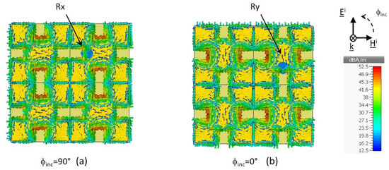
Figure 6.
Simulated surface current distribution on the fractal radiators at resonance (f = 2.45 GHz): (a) ϕinc = 90° (x-polarized incident electric field); (b) ϕinc = 0° (y-polarized incident electric field).
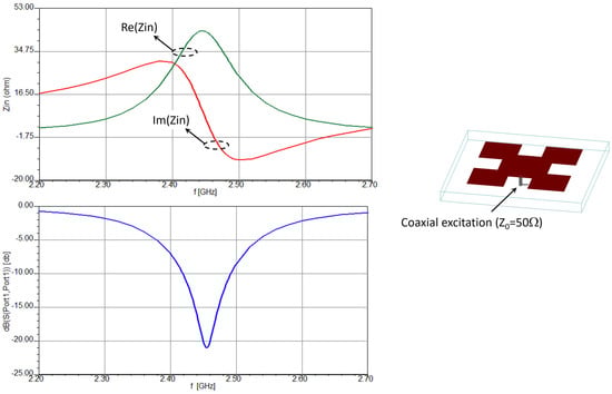
Figure 7.
Input impedance and reflection coefficient of the fractal patch at via location.
3. Harvesting Efficiency Analysis
In order to evaluate the energy harvesting functionalities offered by the proposed configuration, a comprehensive analysis of the loss balance is performed. In particular, to evaluate the amount of the absorbed energy channelized to the loads (i.e., to the rectification circuitry), the ratio between the total power delivered to the loads (Pdel_loads) and the power incident on the metamaterial surface (Pinc) is computed for different directions and polarizations of the impinging electromagnetic wave. The above ratio is defined as the RF-to-AC efficiency, namely η =.
The first subsection reported in the following shows the results of the analysis performed on a periodic unit cell, while the second subsection illustrates the efficiencies of a finite-size metasurface harvester.
3.1. Unit Cell Efficiency Analysis
The power losses within the proposed unit cell are evaluated by the full-wave frequency domain solver CST Microwave Studio. The cell is simulated by imposing the unit cell periodic boundary condition along both x and y directions. The structure is excited by a Floquet port, giving a plane wave normally incident along the z direction; the incident power is set to a value equal to Pinc = 0.5 W. Figure 8 shows the power delivered to the loads under the oblique incidence, namely for different incidence angles θinc starting from 0° up to 60°. In particular, Figure 8a illustrates the power delivered to the resistor located along the y-axis, i.e., Ry in Figure 1, when a y-polarized incident electric field is considered (TE-polarization), while Figure 8b shows the power delivered to the resistor located on the x-axis, i.e., Rx in Figure 1, when an x-polarized field is applied (TM-polarization). In both cases, it can be observed that most of the power is delivered to the load located in the corresponding polarization direction, while only a small amount is dissipated within the copper (≅0.028 Pin), the dielectric (≅0.05 Pin), and the load located outside the polarization direction (≅0.0036 Pin). As a matter of fact, the RF-to-AC efficiency of the unit cell stands at a value equal to about 94.5%, in the case of normal incidence, and it always stays above 85%, also for a wide-angle oblique incidence equal to 60°.
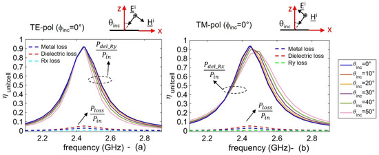
Figure 8.
Unit cell efficiency vs. frequency for different incidence angles: (a) TE-polarization; (b) TM-polarization.
Finally, Figure 9 shows the polarization-insensitive behavior of the unit cell harvesting efficiency. In particular, by varying the polarization angle φinc from 0° up to 180°, the power collected by the cell is proportionally divided between the loads Rx and Ry, in a way that the sum of the two contributions gives a total efficiency still equal to about 94.5%.
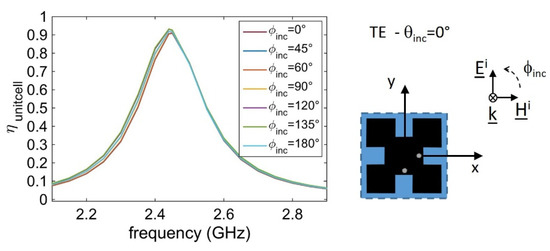
Figure 9.
Unit cell efficiency vs. frequency for different values of the polarization angle φinc at normal incidence.
3.2. Numerical Validation of a 9 × 9 Harvesting Panel
In order to give a preliminary numerical validation of the proposed fractal unit cell, a 9 × 9 metamaterial harvester is designed and simulated with CST Microwave Studio. The metamaterial surface (Aharvester ≅ 1.1λ × 1.1λ) is illuminated by a normal-incidence plane wave having an electric field strength, |Einc|, equal to 1 V/m. By adopting the definition reported in [16,17,18], the RF-to-AC efficiency of the designed metamaterial harvester surface is evaluated as the ability of the absorber to capture the energy per footprint area, namely the ability to transfer the total RF power incident on a specific area to the available AC power received by the harvesters’ collectors (i.e., the total time-average power developed across the resistive loads). Following the above definition, the RF-to-AC efficiency of the finite array is computed as follows:
where the numerator (ΣPdel_load) represents the total power delivered to the loads inside the 9 × 9 cells, while the denominator is equal to the power incident on the array surface, computed as , with parameter Aharvester giving the physical area of the harvester panel [16,17,18] and Sinc the incident power density. In practical cases, the incident power density is calculated by using the Friis equation:
where Pt is the output power of the transmitting antenna, Gt is transmitter antenna gain, and R gives the distance between the transmitter antenna and the harvester surface.
Figure 10 shows the simulated total efficiency of the designed 9 × 9 harvester surface, which is computed for different polarization angles. As it can be observed, a very high and polarization-insensitive harvesting efficiency, equal to about 96.5%, is obtained at a frequency equal to 2.45 GHz, corresponding to a 23.3 μW total power delivered to the loads over a 24.14 μW incident power ().
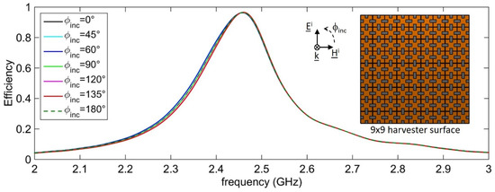
Figure 10.
The 9 × 9 harvester RF-to-AC efficiency vs. frequency for different values of the polarization angle φinc at normal incidence.
As a further validation, the radiation power density pattern of the harvester surface is computed by varying the incidence angle θinc from 0° up to 45°. The pattern is computed in correspondence to the absorber working frequency (f = 2.45 GHz), as well as at a frequency far from the absorption peak (f = 2.6 GHz—See Figure 10). In Figure 11, it can be observed that the radiation power density is very low at f = 2.45 GHz, due to the absorption mechanism, whilst in the case of f = 2.6 GHz, the incident signal is backscattered (i.e., reflected) by the surface along the specular direction, as expected by a uniform array of identical elements [27].
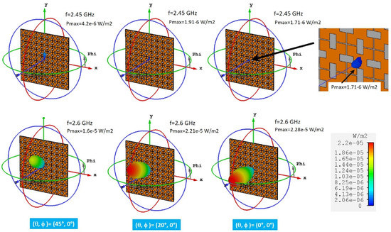
Figure 11.
Radiation power density pattern of the harvester surface for different incidence angles θinc.
Finally, Table 1 shows the main benefits offered by the proposed cell with respect to the configurations recently proposed in literature, namely a good efficiency, a thinner structure, and a smaller unit cell size with respect to most configurations.

Table 1.
Metasurface harvester performances.
The above preliminary numerical results make the proposed structure very appealing for energy-harvesting applications within the 2.45 GHz Wi-Fi frequency band.
As future development, the proposed configuration will be experimentally validated and integrated with a rectification circuit [28]. An intensive measurement campaign will be performed to establish the best approach for rectifying and channeling the collected AC power [15,18].
3.3. Performance of 9 × 9 Harvesting Panel vs. Patch Antenna
In order to provide preliminary evidence of the main benefit offered by a metamaterial (MM) absorber with respect to traditional rectennas [29], namely the ability to harvest a large amount of AC power, the performances of the designed 9 × 9 metasurface panel are compared to those of a microstrip patch placed on the same footprint area of 1.1λ × 1.1λ. The above comparison is functional only to demonstrate the feasibility of the MM technology, by following the approach adopted in [29]. For simplicity, a square patch antenna is considered. The patch is fed by two coaxial probes, in such a way to achieve a dual polarization behavior. The antenna is optimized to offer a maximum gain of about 6 dB in correspondence to 2.45 GHz, for the given 1.1λ × 1.1λ ground plane size. To this end, the patch is printed on a grounded Diclad870 substrate having a thickness of t = 1.524 mm and a dielectric constant equal to εr = 2.33. The antenna sizes are fixed to 38.5 × 38.5 mm2, giving resonance at the operating frequency of 2.45 GHz, while the feeds positions are chosen to satisfy the matching condition (i.e., real(Zin_patch) = 50 Ω) in correspondence to the resonant frequency. Both the harvester and the antenna are illuminated by a normally incident linearly polarized plane wave, oriented along the y-axis, and having an electric field strength, |Einc|, equal to 1 V/m and (see Figure 12). Due to the symmetry of the analyzed structures, the same results are achieved in the case of an x-oriented electric field. The antenna is terminated by pairs of matched loads (i.e., 50 Ω), to ensure maximum power delivery to the loads themselves. As can be observed in Figure 12, the patch is able to capture and deliver a maximum power equal to about 9 μW, against the value of 23.3 μW total power delivered to the MM absorber loads. In conclusion, the MM harvester is able to absorb more power per footprint with respect to the patch antenna, mainly due to the fact that the contribution of each individual cell is constructively added. For this reason, metamaterial-based harvesters can be fruitfully adopted to provide greater amounts of harvested power [29].
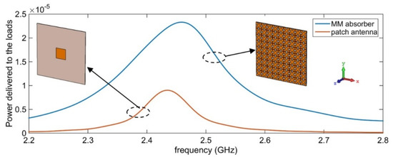
Figure 12.
Total power delivered to the loads: Comparison between the metamaterial (MM) absorber and a patch antenna printed on the same footprint area.
4. Conclusions
A miniaturized metamaterial unit cell has been introduced for ambient energy harvesting applications. An extensive numerical analysis of the unit cell has been performed, demonstrating very high absorption percentages, good angular stability, and very high polarization independence within the 2.45 GHz Wi-Fi frequency band. Finally, a 9 × 9 metamaterial harvester is designed and simulated, demonstrating a very high RF-to-AC efficiency, equal to 96.5%. Furthermore, the finite-size harvester shows a polarization-insensitive behavior, making the proposed configuration very appealing for the implementation of environmentally friendly energy harvesting solutions.
As future developments, the proposed configuration will be further investigated and optimized, in terms of a specific synthesis procedure [30], to add multi-band functionalities for practical IoT applications. Furthermore, the proposed metamaterial configuration will be integrated with a proper rectifier circuit block for a full experimental validation.
Author Contributions
The individual contributions of authors are specified as follows: Conceptualization, S.C. and F.V.; Methodology, S.C. and F.V.; Software, F.V.; Validation, S.C. and F.V.; Writing—Original draft preparation, F.V.; Writing—Review and editing, S.C.; Supervision, S.C. All authors have read and agreed to the published version of the manuscript.
Funding
This research received no external funding.
Conflicts of Interest
The authors declare no conflict of interest.
References
- Romer, K.; Mattern, F. The Design Space of Wireless Sensor Networks. IEEE Wirel. Commun. 2004, 11, 54–61. [Google Scholar] [CrossRef]
- Lobaccaro, G.; Carlucci, S.; Löfström, E. A Review of Systems and Technologies for Smart Homes and Smart Grids. Energies 2016, 9, 348. [Google Scholar] [CrossRef]
- Schwiebert, L.; Gupta, S.K.; Weinmann, J. Research Challenges in Wireless Networks of Biomedical Sensors, in MobiCom ′01. In Proceedings of the 7th Annual International Conference on Mobile Computing and Networking, Rome, Italy, 16–21 July 2001; pp. 151–165. [Google Scholar]
- Kung, H.T.; Vlah, D. Efficient Location Tracking Using Sensor Networks, in WCNC 2003. In Proceedings of the IEEE Wireless Communications and Networking Conference, New Orleans, LA, USA, 16–20 March 2003; pp. 1954–1962. [Google Scholar]
- Chu, Z.; Engmann, F.; Katsriku, F.A.; Abdulai, J.; Adu-Manu, K.S.; Banaseka, F.K. Prolonging the Lifetime of Wireless Sensor Networks: A Review of Current Techniques. Wirel. Commun. Mob. Comput. 2018, 2018, 8035065. [Google Scholar] [CrossRef]
- Patel, A.C.; Vaghela, M.P.; Bajwa, H.; Patra, P.K. Power harvesting for low power wireless sensor network. In Proceedings of the 2009 Loughborough Antennas & Propagation Conference, Loughborough, UK, 16–17 November 2009; pp. 633–636. [Google Scholar]
- Kim, S.; Vyas, R.; Bito, J.; Niotaki, K.; Collado, A.; Georgiadis, A.; Tentzeris, M.M. Ambient RF Energy-Harvesting Technologies for Self-Sustainable Standalone Wireless Sensor Platforms. Proc. IEEE 2014, 102, 1649–1666. [Google Scholar] [CrossRef]
- Brown, W. Experiments in the transportation of energy by microwave beam. Proc. IRE Int. Conv. Rec. 1964, 12, 8–17. [Google Scholar]
- Valenta, C.R.; Durgin, G.D. Harvesting wireless power: Survey of energy-harvester conversion efficiency in far-field, wireless power transfer systems. IEEE Microw. Mag. 2014, 15, 108–120. [Google Scholar]
- Zakaria, Z.; Zainuddin, N.A.; Husain, M.N.; Mutalib, M.A.; Othman, A.R.; Abd, A.; Mohamad, Z. Current Developments of RF Energy Harvesting System for Wireless Sensor Networks. Adv. Inf. Sci. Serv. Sci. 2013, 5, 328–338. [Google Scholar] [CrossRef]
- Akkermans, J.A.G.; van Beurden, M.C.; Doodeman, G.J.N.; Visser, H.J. Analytical models for low-power rectenna design. IEEE Antennas Wirel. Propag. Lett. 2005, 4, 187–190. [Google Scholar] [CrossRef]
- Falkenstein, E.; Roberg, M.; Popovic, Z. Low-power wireless power delivery. IEEE Trans. Microw. Theory Tech. 2012, 60, 2277–2286. [Google Scholar] [CrossRef]
- Ramahi, O.M.; Almoneef, T.S.; AlShareef, M.; Boybay, M.S. Metamaterial particles for electromagnetic energy harvesting. Appl. Phys. Lett. 2012, 101, 173903. [Google Scholar] [CrossRef]
- Alavikia, B.; Almoneef, T.S.; Ramahi, O.M. Electromagnetic energy harvesting using complementary split-ring resonators. Appl. Phys. Lett. 2014, 104, 163903. [Google Scholar] [CrossRef]
- El Badawe, M.; Almoneef, T.S.; Ramahi, O.M. A metasurface for conversion of electromagnetic radiation to DC. AIP Adv. 2017, 7, 035112. [Google Scholar] [CrossRef]
- Ghaderi, B.; Nayyeri, V.; Soleimani, M.; Ramahi, O.M. Pixelated Metasurface for Dual-Band and Multi-Polarization Electromagnetic Energy Harvesting. Sci. Rep. 2018, 8, 13227. [Google Scholar] [CrossRef]
- Almoneef, T.S.; Erkmen, F.; Ramahi, O.M. Harvesting the energy of multi-polarized electromagnetic waves. Sci. Rep. 2017, 7, 14656. [Google Scholar] [CrossRef] [PubMed]
- Ashoor, A.Z.; Ramahi, O.M. Polarization-independent cross-dipole energy harvesting surface. IEEE Trans. Microw. Theory Tech. 2019, 67, 1130–1137. [Google Scholar] [CrossRef]
- Shang, S.; Yang, S.; Shan, M.; Liu, J.; Cao, H. High performance metamaterial device with enhanced electromagnetic energy harvesting efficiency. AIP Adv. 2017, 7, 105204. [Google Scholar] [CrossRef]
- Hu, W.; Yang, Z.; Zhao, F.; Wen, G.; Li, J.; Huang, Y.; Inserra, D.; Chen, Z.D. Low-Cost Air Gap Metasurface Structure for High Absorption Efficiency Energy Harvesting. Int. J. Antennas Propag. 2019, 2019, 1727619. [Google Scholar] [CrossRef]
- Yu, F.; Yang, X.; Zhong, H.; Chu, C.; Gao, S. Polarization-insensitive wide-angle-reception metasurface with simplified structure for harvesting electromagnetic energy. Appl. Phys. Lett. 2018, 113, 123903. [Google Scholar] [CrossRef]
- Costanzo, S.; Venneri, F. Miniaturized fractal reflectarray element using fixed-size patch. IEEE Antennas Wirel. Propag. Lett. 2014, 13, 1437–1440. [Google Scholar] [CrossRef]
- Costanzo, S.; Venneri, F.; Di Massa, G.; Borgia, A.; Costanzo, A.; Raffo, A. Fractal reflectarray antennas: State of art and new opportunities. Int. J. Antennas Propag. 2016, 2016, 7165143. [Google Scholar] [CrossRef]
- Venneri, F.; Costanzo, S.; Di Massa, G. Fractal-shaped metamaterial absorbers for multireflections mitigation in the UHF band. IEEE Antennas Wirel. Propag. Lett. 2018, 17, 255–258. [Google Scholar] [CrossRef]
- Venneri, F.; Costanzo, S.; Borgia, A. A dual-band compact metamaterial absorber with fractal geometry. Electronics 2019, 8, 879. [Google Scholar] [CrossRef]
- Costanzo, S.; Venneri, F.; Borgia, A.; Massa, G.D. Dual-band buallinear polarization reflectarray for mmWaves/5G applications. IEEE Access 2020, 8, 78183–78192. [Google Scholar] [CrossRef]
- Balanis, C.A. Antenna Theory: Analysis and Design; John Wiley & Sons: New York, NY, USA, 2016. [Google Scholar]
- Li, L.; Zhang, X.; Song, C.; Huang, Y. Progress, challenges, and perspective on metasurfaces for ambient radio frequency energy harvesting. Appl. Phys. Lett. 2020, 116, 060501. [Google Scholar] [CrossRef]
- Almoneef, T.S.; Ramahi, O.M. Split-Ring Resonator Arrays for Electromagnetic Energy Harvesting. Prog. Electromagn. Res. B 2015, 62, 167–180. [Google Scholar] [CrossRef]
- Costanzo, S.; Venneri, F.; Di Massa, G.; Angiulli, G. Synthesis of microstrip reflectarrays as planar scatterers for SAR interferometry. Electron. Lett. 2003, 39, 266–267. [Google Scholar] [CrossRef]


© 2020 by the authors. Licensee MDPI, Basel, Switzerland. This article is an open access article distributed under the terms and conditions of the Creative Commons Attribution (CC BY) license (http://creativecommons.org/licenses/by/4.0/).