Article

Development of an Electromagnetic Actuator for the Hot-Embossing Process

Department of Robotics Engineering, Daegu Gyeongbuk Institute of Science and Technology (DGIST), Daegu 42988, Korea
*
Author to whom correspondence should be addressed.
Electronics 2020, 9(6), 948; https://doi.org/10.3390/electronics9060948
Submission received: 28 March 2020 / Revised: 31 May 2020 / Accepted: 5 June 2020 / Published: 8 June 2020

Abstract

:
Hot embossing is in the spotlight due to the development of electronic devices, wearable devices, microfluidic channels, and optical devices. The conventional hot-embossing process creates a pattern on polymer film by using a previously patterned stamp that applied heat and pressure. This method has a disadvantage because it depends on the shape of the patterned stamp. For this reason, this method requires a high cost and a lot of time when replacing the stamp for making a new pattern shape or for modifying the error of the pattern. To solve this problem, the impact print-type hot-embossing method was proposed to create arbitrary patterns, and equipment for this method was assembled. In addition, patterning experiments were conducted to imprint several tens of micrometer-sized patterns in real time. For this method, we proposed an electromagnetic actuator for making the hot-embossing print type and for reducing the size of the actuator compared to previous studies. Through the patterning experiment, we determined that the proposed device could engrave fine dot patterns ranging from 60 μm to 120 μm in diameter. We verified the size of the generated pattern by using a confocal microscope, and we found the proposed hot-embossing technology can realize the desired shape in any position by using the proposed technique.

1. Introduction

Many industrial fields like electronics and biomedical applications require a fine patterning process when making various types of devices. For this reason, not only are the optical method and chemical etching technique used to make a fine pattern, but also the hot-embossing process using heat and pressure.
Hot embossing technology is a fine processing method that can generate micro and nanoscale patterns on polymer film heated above the glass transition temperature by using a patterned stamp. To harden the generated pattern, a cooling process is applied to the polymer film after forming the pattern. The hot-embossing process requires a pressurizing mechanism, heating mechanism, and stamp having a fine pattern. This process is simple and does not need to discharge pollutants, so this method has been widely researched in micro and nanoscale patterning fields.
This method can be applied to mass-produced disposable microfluidic devices for low-cost production [1], and the roll-to-roll method for hot embossing is also studied to improve productivity [2]. Recently, not only heat and pressure but also ultrasonic vibration have been applied to improve the embossing quality [3]. Sparks can also be used together with the hot-embossing process [4]. Modified processes using hot embossing are also under study, such as the study of heating a contact surface using a laser on the opposite side of a glass plate while pressing the glass plate with a mold to emboss the glass [5].
Many researchers have studies the microdevices in the form of chips focusing on the biomedical field [6], and nanofiber arrays have been realized using thermoplastic materials that used a hot-embossing method in place of conventional methods such as the deposition of nickel, another metal on silicon dioxide dry etching method, and patterned resist substrates (Lithographie, Galvanoformung, Abformung (LIGA) processes) [7]. In addition, many areas of research such as nanoscale patterning in fluorinated ethylene propylene (FEP) [8], the production of energy-harvesting devices using field-emission display [3], and the generation of gradient porous microneedles [9] have been investigated.
Therefore, the conventional hot-embossing method generates a pattern using a patterned stamp by applying pressure and heat to the polymer film. Conventional hot-embossing equipment such as the roller type or plate type can be mainly used in the hot-embossing process, and the pattern of the stamp is made by engraving the micro or nanoscale patterns directly on the stamp [10] or by applying the imprinted substrate on this stamp [11]. When engraving a fine pattern roll or preparing a stamp, this conventional hot-embossing method is significantly disadvantageous because the fabrication cost to make a fine pattern on the stamp is expensive and time-consuming.
In addition, in the roll-to-roll hot-embossing process, the micro or nanoscale patterns are directly engraved on the roller. Therefore, in the case of changing the patterning process, the high-cost rolls or stamps must be replaced to change the pattern shape. For this reason, to solve the disadvantage of pattern replacement in the conventional hot-embossing process, our research team proposed “impact print-type” hot-embossing technology [12]. Impact print-type hot embossing refers to the method of a line printer or a dot printer imprinting microscale patterns on a substrate by striking it with a minute probe or printer head. This method can generate a dot pattern several μm in size by using a single impact, and it can generate arbitrary patterns that have various widths and depths by adjusting the positions of the impact actuator. In contrast to conventional hot-embossing equipment, the impact print-type hot-embossing method can flexibly generate various fine patterns in real-time by connecting small patterns that have arbitrary shapes or points formed using the impact header. The conventional hot-embossing device has the disadvantage that whole stamps, such as flat or roll types, need to be replaced or newly manufactured when modifying or changing the pattern shape. For this reason, conventional hot embossing has a high cost and is time-consuming. On the other hand, the impact print-type hot-embossing method has the significant advantage that it can generate various patterns in real time without replacing stamps due to the electromagnetic actuator.
In this paper, a fundamental experiment with the impact print-type hot-embossing process was performed, and the experiment was conducted to understand the characteristics of the impact print-type hot-embossing process. Notably, we significantly reduced the size of the electromagnetic actuator compared to the previous actuator and performed embossing experiments using the implemented smaller electromagnetic actuator. This research was presented at the 23rd International Conference on Mechatronics Technology (ICMT 2019) [13], and it was selected for a Special Issue in Electronics by ICMT 2019 and updated for submission to this journal.

2. Development of Actuator for Hot Embossing

2.1. Analysis

In this section, we deal with the design and implementation of the device for experimenting with the proposed hot-embossing method. In order to implement the hot-embossing technology, the hot-embossing process requires a pressure of about 30 to 50 MPa, or more, and the electromagnetic actuator should be developed with sufficient force to generate the required pressure. To realize this method, the electromagnetic actuator with 50 mm length and 15 mm diameter was used as developed in a previous study [12]. However, due to the huge size and heavy weight of the device, it was difficult to realize the equipment using the previous actuator model. To solve this problem, we developed a new type of electromagnetic actuator that had 30 mm length and 6 mm diameter. It could be determined that the implemented actuator should be able to produce a pressure of 30–50 MPa, or more, from the previous studies [14,15,16,17]. We set the target pressure value to approximately 100 MPa in consideration of safety. We conducted the impact print-type hot-embossing experiment using the developed actuator in the next section.
Design and analysis of coils and cores to generate the required force is essential to miniaturize the actuator. To design a smaller actuator, we need to determine the size of the impact head tip firstly. Table 1 shows calculation results for determining the size of the impact head tip for the required pressure. As shown in this table, we can determine that the actuator with a tip of 30 μm diameter can be applied to the hot-embossing process if a force from 0.02 N to 0.07 N can be generated, as 30–100 MPa pressure is sufficient for the hot-embossing process considering safety factors.
We used the finite element method and commercial software called “Maxwell” for the analysis of the electromagnetic actuator. Figure 1 presents the finite element model for the performance analysis of the hot-embossing impact actuator. As shown in this figure, the actuator is composed of a magnetic core, wound coil, and an impact pin. With the applied current to the coil, electromagnetic force is generated to move the impact pin. The coil diameter was set to 0.2 mm.
Figure 2 shows the magnetic field distribution, which is one of the results of the electromagnetic field analysis. The left figure of Figure 2 shows the distribution of the electromagnetic flux line, and the right figure shows the distribution of the magnetic flux density. From this figure, it can be seen that the electromagnetic field was well distributed with no flux leakage along the designed core. Figure 3 shows the results of the electromagnetic force analysis using the finite element model. The results show the generated force when the current applied to the coil was 0–0.15 A and the displacement of the core was 0–300 μm. As a result, it was found that the maximum force was about 1–5 N, which is sufficiently larger than the required force in the theoretical analysis shown in Table 1. Therefore, it was found that the embossing experiment could be carried out using the designed actuator, so we decided to make a second prototype based on this design.
Figure 2 shows how the magnetic flux and magnetic density are distributed in the core as from the electromagnetic finite element (FE) analysis. The figure on the left shows the electromagnetic field distribution, and the right figure shows the magnetic flux density distribution. As shown in this figure, it can be determined that there was little leakage around the magnetic core model. The analytical results of electromagnetic force according to the applied current are shown in Figure 3. The electromagnetic force with varied current from 0 A to 0.015 A was plotted in this figure when the mover moved from 0 μm to 300 μm. The initial position of the mover was where the distance from the core was maximum and where the air gap was 300 μm. The analysis was performed while reducing the air gap by 100 μm.
The results showed that the newly designed actuator could generate sufficient force of 1–5 N, as this value is larger than the required force presented in Table 1. Therefore, it was determined that the newly designed compact impact actuator could be sufficiently applied and used in the hot-embossing process.

2.2. Impact Actuator Performance Evaluation

This section describes the design and fabrication of the proposed actuator prototype using the results obtained in the previous section. The prototype was devised to have a linear spring to position the impact pin to the initial position after embossing. So, the applied current generates an electromagnetic field that can move the pin, and the restoration force of the spring makes the pin move backwards. Figure 4 shows a drawing and picture of the actuator.
Next, we conducted experiments to measure the electromagnetic force of the impact actuator to verify its performance. To do this, a two-axis position system was prepared, and the gap between the load cell and actuator on the bottom was varied using the z-axis position system. The force generated was measured according to the gap difference while the wound coil was energized. Figure 5 shows an experimental setup for measuring the force.
Voltage was applied to the driver to operate it, and the applied voltage ranged from 0 V to 10 V. Figure 6 shows the result of measuring the force of the driver in a graph, and it was found that the maximum force of the driver was 1.3 N. If this value was converted to the pressure of the pin end, it was about 650 MPa, which is enough pressure for use in the hot-embossing process. Therefore, it was confirmed that the developed actuator had sufficient performance to produce the required force.

3. Embossing Patterning Using the Impact-Type Actuator

This section deals with an experiment of the hot-embossing patterning using the developed electromagnetic actuator, and the embossing performance was validated by investigating the generated patterns.
First, in order to reduce vibration from the outside, an anti-vibration table was prepared, and a flat plate heater capable of heating up to 350 degrees was placed on the table. The polymethyl methacrylate (PMMA) film was attached to the upper surface of the heater using insulated tape. The two-axis stage (M-531.2S1, L-511.20SD00, PI) was then fitted vertically to each other using aluminum jigs, then installed on the table, and an impact driver was assembled and developed on the z-axis stage. The surface of the jig near the heater was wrapped with aluminum tape to prevent it from heating, as shown in Figure 7. A personal computer (PC) was used as the main controller, and the operation system was coded using Labview to control the two-axis stage and impact header.
The control program was designed to control the speed, distance of operation, driving frequency of the two-axis stage, and phase of the impact head. Using the data acquisition (DAQ) board (USB-6211, National Instruments, Austin, TX, USA), the square wave control signal from the PC was passed to the driver. A driver was devised using an operational amplifier (OP-amp) (OPA2541, Texas Instruments, Dallas, TX, USA) to amplify the control signal to the proper level. The film was prepared by cutting to a width of 150 mm and a length of 70 mm, and the temperature of the heater for the experiment was changed between 80 °C and 100 °C considering the glass temperature of 100 °C of the film.
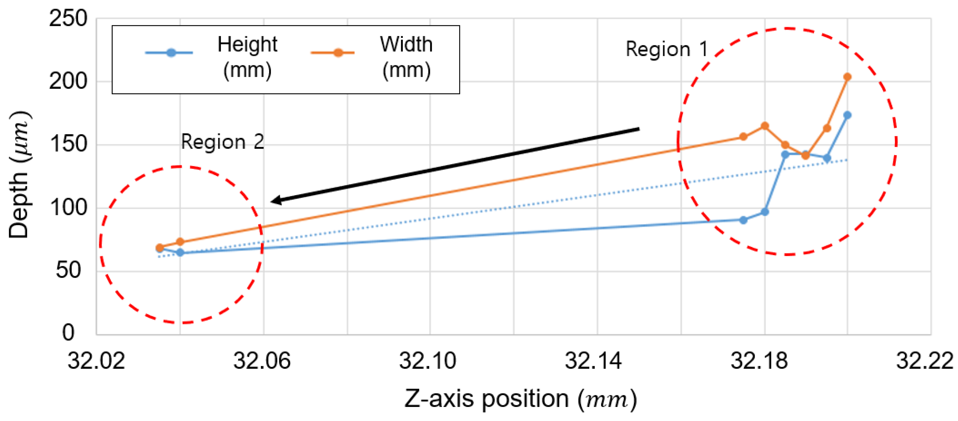
Using the prepared equipment, film patterning was performed while increasing the height of the z-stage in the vicinity of 32 mm in 5 µm increments. For the experiment, a PMMA film having a thickness of 125 μm was used, and the temperature of the heat plate was set to 100 °C. In addition, the X-stage value was shifted by 300 µm for each Z-stage section, patterning was performed in three points, and a gap of 500 µm was spaced when the Z-stage setting was changed.
The film pattern was measured while changing the Z-stage height. The depth and width of the pattern were measured using a confocal microscope, and the measured results are shown in Figure 8. As can be seen in the figure, when the height of the z-axis was 32.2 mm, the pattern depth was 174 µm, the pattern width was about 203.8 µm, and the shape of the pattern measured using a confocal microscope at this condition is shown in Figure 9.
Throughout this experiment, the depth tended to decrease as the height decreased in the experimental section. In this study, the goal was to create a pattern with a depth and width of about 60–70 µm, so we reduced the height of the z stage to reach this value. When the height of the z stage was 32.035 mm, the desired pattern having a size of 150 μm pitch, 61 μm pattern depth, and 60 μm pattern width was obtained as shown in Figure 10.
Through these experiments, it was found that by using the developed equipment, hot-embossing patterns of various sizes can be generated if the process parameters are controlled properly. Since the size of the pattern is determined according to the temperature and the operating distance of the driver, experiments that change these parameters are needed to obtain the desired pattern, and the pattern changes should be investigated. By this procedure, the conditions for the target embossed patterns can be found.
Next, the influence of heating temperature on patterning was examined. Since it is impossible to heat the temperature of the film to 100 °C or more, the effect of temperature on the width and depth of the pattern was examined when the temperature was changed from 100 °C to 80 °C in 10 °C increments. Figure 11 shows the experimental results. At 80 °C, the height of the pattern was 118 µm and the width was 98.15 µm. At 90 °C, the height and width of the pattern were 80 µm and 80.65 µm, respectively, and at 100 °C it was found that the height and width were 60 µm and 62.52 µm. This study confirmed that the temperature of 100 °C is suitable for our purpose of obtaining patterns with a size of 60 µm. It is estimated that the depth of the pattern becomes shallower as the temperature increases due to the reflow phenomenon. It was also interesting that the difference in depth and width decreased as the temperature increased.
Finally, an experiment was conducted to see if multiple patterns could be taken in succession. In order to apply the developed impact-type hot-embossing process technology to the fields of microfluidic channels and conductive patterns, etc., it is necessary to be able to generate several patterns in a dot form continuously. Therefore, a continuous pattern was taken using the equipment developed. To achieve this, it is necessary to make and connect dots with a pitch smaller than the size of the pattern.
We coded the control program of the stage and embossed five dots side by side, and the result is shown in Figure 12. In the result measured by a confocal microscope, as shown in the figure, the unevenness of the bottom region was caused by the pointed pin impacting the substrate, which is characteristic of the proposed hot-embossing process. The wavy shape around the edge in Figure 12 was from the characteristics of the confocal microscope. In order to measure such a small pattern, the confocal microscope uses light on the pattern and optically measures the reflected light. Therefore, the reflection or refraction of light at the corners characterizes the pattern, resulting in a wavy and noisy shape. As a result, it was possible to successfully create a continuous pattern in which five dots having a uniform depth of 65 µm were taken adjacent to each other.

4. Conclusions

In this paper, we developed an electromagnetic actuator for use in the impact-type hot-embossing process. Compared to the conventional hot-embossing process, which can engrave only a predetermined pattern, this technology has been proposed to develop patterns of very small dots and connecting them to generate arbitrary patterns in real time.
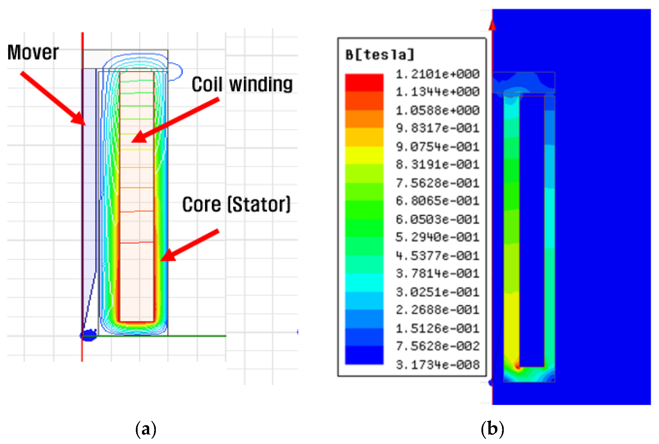
To do this, the impact-type embossing process was realized using the developed electromagnetic impact actuator, and 60–70 μm patterns were formed through the actual embossing process. In order to create the impact actuator, a new actuator was designed and manufactured using the principle of electromagnetic actuation, and a finite element analysis method was used for this. Through this, it was possible to obtain enough force required for hot embossing. Therefore, the hot-embossing system can be realized using a smaller electromagnetic actuator than that used in previous studies.
Experiments were performed to obtain the desired patterns using the developed equipment. The objective of the experiment was to create an embossing pattern with a width and depth of 60–70 μm. To obtain the desired pattern, a number of experiments were performed using the actuator’s height and the temperature of the heating plate as variables.
In this way, an appropriate position of the actuator could be determined, and a hot-embossing pattern having a width of 60 μm and a depth of 61 μm at a heating temperature of 100 °C could be made. In order to create an arbitrary pattern, since small dot patterns must be continuously generated side by side, five dot patterns were embossed on the PMMA film. In this way, a linear pattern with a depth of 65 μm was successfully achieved.
In this study, we developed an electromagnetic actuator to implement an impact-type hot-embossing process that can create arbitrary patterns in real time, unlike the existing hot-embossing process. If the impact-type hot-embossing process is successfully implemented using the developed actuator, the time and cost required to replace the pattern in the hot-embossing process can be drastically reduced. In addition, by using the proposed technology, it is expected that any shape can be formed in real time, so it can be widely used in research fields such as micro-fluids and conductive patterns in the future.

Author Contributions

Conceptualization, D.Y.; Data curation, M.K.; Formal analysis, D.Y.; Investigation, M.K.; Supervision, D.Y.; Writing—original draft, D.Y.; Writing—review & editing, D.Y.; All authors have read and agreed to the published version of the manuscript.

Funding

This research was funded by the Ministry of Trade, Industry and Energy (MOTIE) under grant N046100024, 2016–2019.

Conflicts of Interest

The authors declare no conflict of interest.

References

  1. Gerlach, A.; Knebel, G.; Guber, A.; Heckele, M.; Herrmann, D.; Muslija, A.; Sshaller, T.H. Microfabrication of single-use plastic microfluidic devices for high-throughput screening and DNA analysis. Microsyst. Technol. 2002, 7, 265–268. [Google Scholar] [CrossRef]
  2. Ahn, S.H.; Guo, L.J. High-speed roll-to-roll nanoimprint lithography on flexible plastic substrates. Adv. Mater. 2008, 20, 2044–2049. [Google Scholar] [CrossRef] [Green Version]
  3. Nguyen, L.; Wu, M.-H.; Hung, C. Finite element analysis of ultrasonic vibration-assisted microstructure hot glass embossing process. Aust. J. Mech. Eng. 2017, 1–10. [Google Scholar] [CrossRef]
  4. Hof, L.A.; Guo, X.; Seo, M.; Wüthrich, R.; Greener, J. Glass imprint templates by spark assisted chemical engraving for microfabrication by hot embossing. Micromachines 2017, 8, 29. [Google Scholar] [CrossRef] [Green Version]
  5. Kurita, T.; Ogura, I.; Ashida, K. Proposal of laser assisted hot embossing technology for glass. J. Mater. Process. Technol. 2018, 254, 248–253. [Google Scholar] [CrossRef]
  6. Truckenmüller, R.; Giselbrecht, S.; Rivron, N.; Gottwald, E.; Saile, V.; Van den Berg, A.; Wessling, M.; Van Blitterswijk, C. Thermoforming of film-based biomedical microdevices. Adv. Mater. 2011, 23, 1311–1329. [Google Scholar] [CrossRef] [PubMed]
  7. Boesel, L.F.; Greiner, C.; Arzt, E.; Del Campo, A. Gecko-inspired surfaces: A path to strong and reversible dry adhesives. Adv. Mater. 2010, 22, 2125–2137. [Google Scholar] [CrossRef] [PubMed]
  8. Cheng, E.; Yin, Z.; Zou, H.; Jurčíček, P. Experimental and numerical study on deformation behavior of polyethylene terephthalate two-dimensional nanochannels during hot embossing process. J. Micromech. Microeng. 2013, 24, 015004. [Google Scholar] [CrossRef]
  9. Li, J.; Zhou, Y.; Yang, J.; Ye, R.; Gao, J.; Ren, L.; Liu, B.; Liang, L.; Jiang, L. Fabrication of gradient porous microneedle array by modified hot embossing for transdermal drug delivery. Mater. Sci. Eng. C 2019, 96, 576–582. [Google Scholar] [CrossRef] [PubMed]
  10. Yun, D.; Son, Y.; Park, H.; Kim, B.; Kim, S. Study on the roll-to-roll hot embossing with a presurized belt. In Proceedings of the 2013 13th International Conference on Control, Automation and Systems (ICCAS 2013), Gwangju, Korea, 20–23 October 2013; pp. 485–487. [Google Scholar]
  11. Yun, D.; Son, Y.; Kyung, J.; Park, H.; Park, C.; Lee, S.; Kim, B. Development of roll-to-roll hot embossing system with induction heater for micro fabrication. Rev. Sci. Instrum. 2012, 83, 015108. [Google Scholar] [CrossRef] [PubMed]
  12. Yun, D.; Kim, J.; Kim, M.; Kim, D.Y.; Kwon, J.; Hwang, J. Impact Print-Type Hot Embossing Process Technology. Adv. Eng. Mater. 2018, 20, 1800386. [Google Scholar] [CrossRef]
  13. Yun, D.; Kim, M.; Ahn, J. Study on the Patterning Process using an Electromagnetic Actuator. In Proceedings of the 2019 23rd International Conference on Mechatronics Technology (ICMT), Salerno, Italy, 23–26 October 2019; pp. 1–5. [Google Scholar]
  14. Becker, H.; Heim, U. Hot embossing as a method for the fabrication of polymer high aspect ratio structures. Sens. Actuators A Phys. 2000, 83, 130–135. [Google Scholar] [CrossRef]
  15. Yeo, L.; Ng, S.; Wang, Z.; Xia, H.; Wang, Z.; Thang, V.; Zhong, Z.; De Rooij, N.F. Investigation of hot roller embossing for microfluidic devices. J. Micromech. Microeng. 2009, 20, 015017. [Google Scholar] [CrossRef]
  16. Omar, F. Hot Embossing Process Parameters: Simulation and Experimental Studies. Ph.D. Thesis, Cardiff University, Cardiff, UK, 2013. [Google Scholar]
  17. Peng, L.; Deng, Y.; Yi, P.; Lai, X. Micro hot embossing of thermoplastic polymers: A review. J. Micromech. Microeng. 2013, 24, 013001. [Google Scholar] [CrossRef]
Figure 1. Finite element modeling for actuator analysis.
Electronics 09 00948 g001
Figure 2. Electromagnetic field analysis result. (a) Magnetic flux line; (b) magnetic flux density.
Electronics 09 00948 g002
Figure 3. Electromagnetic force analysis results.
Electronics 09 00948 g003
Figure 4. Prototype drawings of the impact head actuator. (a) 3D drawing, (b) manufactured actuator.
Electronics 09 00948 g004
Figure 5. Experimental apparatus for measuring the force of an actuator.
Electronics 09 00948 g005
Figure 6. Performance test results of the impact actuator (number of samples = 5 for each displacement). (a) Electromagnetic force according to pin displacement. (b) Pressure at the end of the pin according to displacement of the pin.
Electronics 09 00948 g006
Figure 7. Experimental apparatus for patterning.
Electronics 09 00948 g007
Figure 8. Pattern size change according to the height of the z axis.
Electronics 09 00948 g008
Figure 9. Measurement of pattern shape and size (z = 32.2 mm).
Electronics 09 00948 g009
Figure 10. Measurement of pattern shape and size (z = 32.035 mm).
Electronics 09 00948 g010
Figure 11. Effect of temperature on the pattern width and depth.
Electronics 09 00948 g011
Figure 12. Experimental results of five consecutive pattern formations.
Electronics 09 00948 g012
Table 1. Calculation of the necessary force for the hot-embossing process.
Dia (mm)Required Press (Pa)Area (m2)Force (N)Force (kg)
0.0330,000,0007.06858 × 10−100.0212060.002162
0.03100,000,0007.06858 × 10−100.0706860.007208
0.06100,000,0002.82743 × 10−90.2827430.028831

