Article

Fast Hole Filling for View Synthesis in Free Viewpoint Video

Department of Computer Science and Information Engineering, National Formosa University, Yunlin 632, Taiwan
*
Author to whom correspondence should be addressed.
Electronics 2020, 9(6), 906; https://doi.org/10.3390/electronics9060906
Submission received: 21 April 2020 / Revised: 26 May 2020 / Accepted: 26 May 2020 / Published: 29 May 2020
(This article belongs to the Special Issue Multimedia Systems and Signal Processing)

Abstract

:
The recent emergence of three-dimensional (3D) movies and 3D television (TV) indicates an increasing interest in 3D content. Stereoscopic displays have enabled visual experiences to be enhanced, allowing the world to be viewed in 3D. Virtual view synthesis is the key technology to present 3D content, and depth image-based rendering (DIBR) is a classic virtual view synthesis method. With a texture image and its corresponding depth map, a virtual view can be generated using the DIBR technique. The depth and camera parameters are used to project the entire pixel in the image to the 3D world coordinate system. The results in the world coordinates are then reprojected into the virtual view, based on 3D warping. However, these projections will result in cracks (holes). Hence, we herein propose a new method of DIBR for free viewpoint videos to solve the hole problem due to these projection processes. First, the depth map is preprocessed to reduce the number of holes, which does not produce large-scale geometric distortions; subsequently, improved 3D warping projection is performed collectively to create the virtual view. A median filter is used to filter the hole regions in the virtual view, followed by 3D inverse warping blending to remove the holes. Next, brightness adjustment and adaptive image blending are performed. Finally, the synthesized virtual view is obtained using the inpainting method. Experimental results verify that our proposed method can produce a pleasant visibility of the synthetized virtual view, maintain a high peak signal-to-noise ratio (PSNR) value, and efficiently decrease execution time compared with state-of-the-art methods.

1. Introduction

Owing to the current technological era and the rapid development of digitalization, trends in three-dimensional (3D) videos and imaging technology are developing. The recent emergence of 3D movies and 3DTV indicates increasing interest in 3D content. Although we live in a 3D world, most TV and computer screens provide only two-dimensional (2D) images. Various improvements in 3D technology have garnered more interest in multiview video (MVV) applications such as 3DTV, which offers depth perception without requiring special glasses. Development based on stereoscopic displays that capture, transmit, and display two separate video streams has been used to develop the 3DTV system [1].
Free-viewpoint television (FTV) is regarded as the ultimate 3DTV; it consists of an infinite number of virtual views and provides viewers the flexibility to freely select a viewpoint for viewing 3D scenes [2,3]. A practical method to obtain a free viewpoint video (FVV) is to create virtual views from multiview images. However, multiview video transmission requires a large bandwidth, thus limiting its use [4]. An alternative approach to solve this problem is to generate virtual views using a single reference texture and its coordinate depth map [1]. Depth-based image rendering (DIBR) is a core technology to generate a virtual view synthesis [1,2,3,4,5,6,7,8,9]. The base concept of DIBR involves the projection of two reference texture views onto a selected virtual view. The neighboring side views (left-side and right-side reference views) with the reference depth maps are backprojected separately to the points on a 2D image into the 3D world coordinates; subsequently, the resulting points in the 3D world coordinates system are reprojected into the 2D virtual image. A virtual view is synthesized by two virtual views warped from the neighboring side views. This process is known as 3D warping [10]. However, the backprojection and reprojection processes generate cracks (holes), ghosts, and disocclusion regions. These cracks (holes) occur owing to sampling in the x-and y-directions of the reference images and inaccurate depth values. Disocclusion regions refer to areas that are nonexistent in the reference view, but become visible from the virtual view, or those that are visible in the reference view, but become invisible in the virtual view. The disocclusion regions are located in the background [6]. The edges of the disocclusion regions may contain artifacts called ghosts, which occur on depth discontinuities [11]. Hence, overcoming holes, ghosts, and disocclusions in the DIBR algorithm based on 3D warping is a major challenge in virtual view synthesis. Several state-of-the-art DIBR algorithms have been proposed to improve the rendering quality by reducing the foregoing challenges [5,6,8,11,12,13,14,15,16].
Owing to the drawback of DIBR, filling disocclusion regions is challenging in view synthesis, because those regions are typically large. Hence, an exemplar-based inpainting algorithm by Criminisi et al. [17] is typically used to fill the large holes and disoccluded regions. This exemplar-based inpainting algorithm by [17] computes the priority for a pixel at a hole boundary according to the confidence term and data term; furthermore, it searches for the optimal patch from the entire source image, in which the patch with the best priority region is selected and pixels within the selected patch are copied to fill the holes. Algorithms such as those reported in [4,12,13] are based on the propagation of the neighborhood information (or rely on the depth information) to overcome holes, ghosts, and disocclusions. Daribo and Saito [12] added depth information to the priority computation involved in the exemplar-based inpainting algorithm by Criminisi et al. Subsequently, Gautier et al. [13] extended Criminisi’s algorithm. They defined the data term using a 3D structure tensor of the Di Zenzo matrix and added the depth information in the best patch calculation module. However, the Di Zenzo matrix could reflect only the strong gradients. Therefore, it will produce blurred results under diffusion during the inpainting. Oh et al. [15] used a histogram matching strategy before blending, such that the side views have similar color conditions with the blended virtual view; additionally, they used the fast matching method (FMM) [18] to achieve hill inpainting. However, this method cannot entirely remove color discontinuities between the unoccluded and disocclusion regions. With and Zinger [16] preprocessed a depth map using a low-pass filter and used a bilateral filter to smooth the boundaries between foregrounds (FGs) and backgrounds (BGs), such that holes and disoccluded regions could be reduced. However, if the depth map after filtering is extremely smooth, the geometric distortion and the rendering view quality will be degraded.
In the exemplar-based inpainting method [17] for hole filling, FG textures are prone to be mapped to disoccluded regions using the original inpainting method [17]. This is a mistake because missing information is derived from the BG region. To solve this problem, Muddala et al. [11] used layered depth images warped from 3D warping to segment the BG and FG and then extracted the boundary between them based on a depth threshold; the combined depth information and the hole boundary belonged to the BG and hole filling was achieved using the inpainting algorithm. The inpainting algorithm of [11] modified the filling priority order, including the depth information to favor BG pixels. However, a different order does not guarantee that the FG information will not be propagated to holes in the virtual view. Several algorithms [4,11,13,19,20] are based on changing the filling priority order.
Cheng et al. [21] proposed a DIBR method based on inverse warping and a depth value to remove holes and inpainting, based on the exemplar-based method [17]. Using the dilation process to avoid ghosts that appear on the edges of disocclusions, Yang et al. [8] proposed a statistical method for removing color discontinuities; in this method, the brightness of one side view is used as a base to adjust that of another side view. Subsequently, holes were filled by the depth-assistance asymmetric dilation inpainting method. Zarb and Debono [22] improved Yang et al.’s [8] method, that used depth data to extract the BG regions; they used the brightness of the BG regions as a base to adjust the brightness. Finally, by utilizing depth information to determine the hole nature and to subsequently select the appropriate neighboring pixels, hole filling was interpolated using the method in [6].
In addition, several approaches [23,24,25,26] proposed hole filling methods based on BG construction from a succession of frames and using the available information in a temporal domain. Su et al. [23] used the relation between frames to increase the accuracy of repairing information by the moving behavior and texture similarity. In [24], Sehmeing and Jiang used neighboring pixels from a spatial-temporal window to determine the BG candidates for each pixel to fill in the hole region. Disocclusion filling involves a patch-based inpainting method, but uses superpixels instead of the square of image patches; using superpixels can reduce the number of entities. Although this method can be used to obtain the BGs of the hole regions, it often requires substantial time consumption when camera motion occurs. Lie et al. [25] proposed generating a key-frame sprite BG that is removed from the FG to fill a disocclusion/hole. Luo and Zhu [26] proposed creating a BG video based on the foreground removal and removed positions filling to remove the FGs and then to refill FGs positions from both a 2D image. Its corresponding BG depth created based on the FGs extracted and removed in the depth map by computed 3D warping; subsequently, a BG video and its BG depth map are generated before 3D warping and are used to eliminate holes in the synthesized video. However, the approaches in [25,26] rely heavily on the correct classification of FG regions, which is difficult, especially when several depth layers exist. Oliveira et al. [27] proposed an improved patch-based inpainting that involved the depth term and the BG term in the priority computation to select the best patch. The patch was selected using an erosion process to remove the FG information and to fill the holes. However, the FG–BG classification could not distinguish precisely; it could not remove ghosts on the edges between the FG and BG. Many other approaches fill all holes in a single step using all valid image contents [28,29].
In this study, we focused on the challenges of DIBR to fill the holes/disocclusions in virtual view synthesis. This proposed method includes DIBR with improved 3D warping, filtering, 3D inverse warping, brightness adjustment, blending views, and hole filling to achieve our purpose.
The remainder of this study is organized as follows. Section 2 presents the related techniques. The proposed method is described in Section 3. In Section 4, we present the experimental results that verify the performance of the proposed method. Finally, Section 5 concludes this study.

2. Related Techniques

In this section, we briefly describe the methods applicable to our proposed approach.

2.1. Camera Geometry Model

For 3D warping in DIBR, the camera geometry model is a fundamental framework in generated 3D vision. A general camera is modeled as a pinhole, as shown in Figure 1. C is the camera center and I is the view plane in the camera’s coordinates. The orthogonal axis with a line including C is called the optical axis (Z) and its intersection with I is the principal point (p). m k = ( u , v ) is the coordinates of M in the I plane, which is the projection of W expressed as w = ( x , y , z ) in the world coordinates. A full perspective projection is represented by mapping from 3D to 2D coordinates by a linear transformation in homogenous coordinates [30,31,32]. Let m ˜ = [ u   v   1 ] T and w ˜ = [ x   y   z   1 ] T be homogenous coordinates for M and W, respectively. According to the transformation matrix P ˜ in perspective transformation, the 3D coordinates are transformed to 2D coordinates, expressed as
k m ˜ = P ˜ w ˜
where k is a scale factor called the perceptive depth. k becomes the true orthogonal distance of the point from the local plane to the camera. According to [33], k is expressed as
k = 1 d z 255 ( ( 1 M i n Z ) ( 1 M a x Z ) ) + ( 1 M a x Z ) ,
where d z is the depth value in the depth map; M i n Z and M a x Z denote the nearest and the farthest depth values in the 3D real world, respectively. P ˜ is decomposed into the product
P ˜ = A [ R | t ] 3 × 4 ,
where A 3 × 3 is the camera’s intrinsic parameter matrix, formed by
A = [ k u f γ u 0 0 k v f v 0 0 0 1 ]
Matrix [ R | t ] 3 × 4 indicates the camera’s extrinsic parameters matrix that contains a 3 × 3 rotation matrix R and the vector 3 × 1 translation t between the world plane and the camera plane. k u and k v are the numbers of pixels per unit distance in ( u , v ) coordinates; γ is the skew factor; ( u 0 , v 0 ) are the coordinates of the principal point p given by the intersection of the optical axis and view plane, as shown in Figure 1.

2.2. Traditional 3D Warping

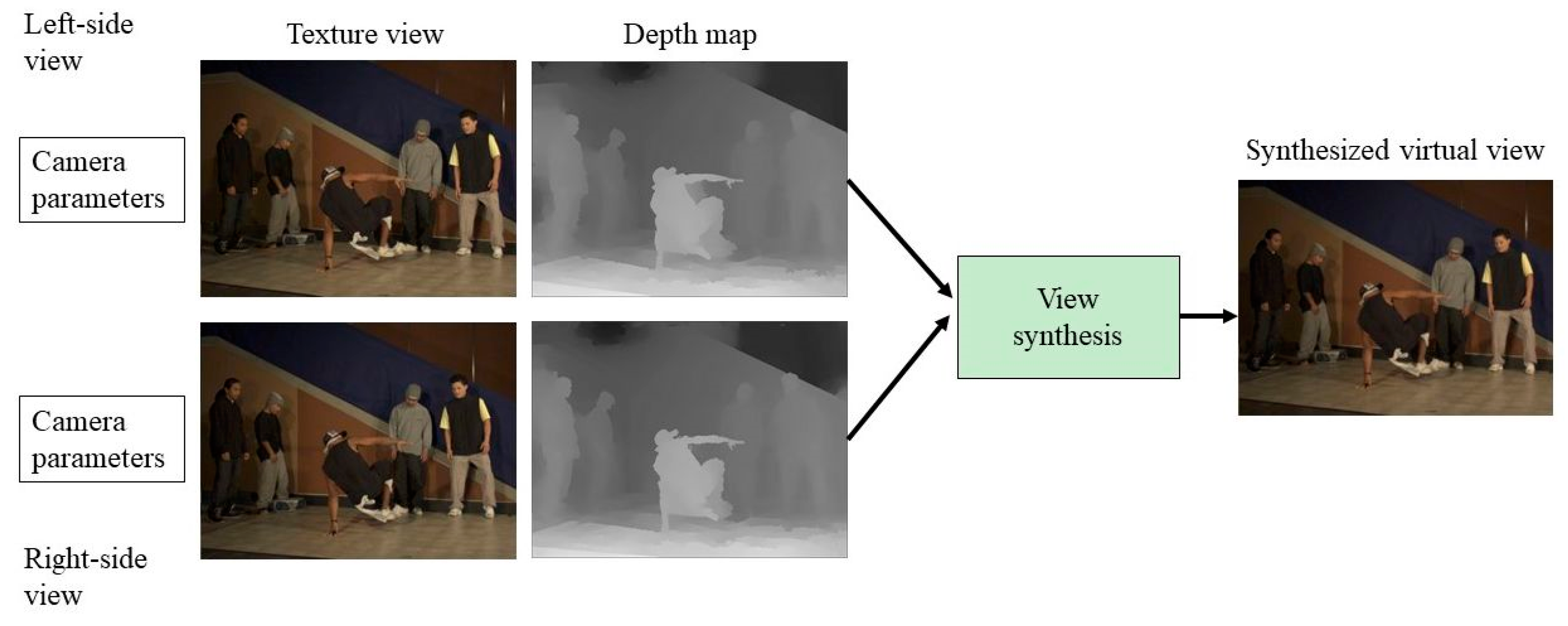
A typical DIBR virtual view synthesis composed of left-side and right-side cameras using the camera parameter, texture image, and depth images, is illustrated in Figure 2. Moreover, 3D warping is the core method to generate a depth-based virtual view synthesis by transferring two side views based on DIBR.
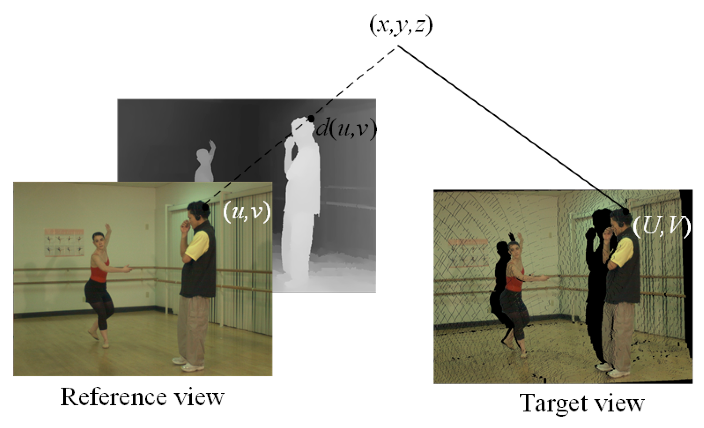
In 3D warping [12], first, a 2D pixel coordinate ( u , v ) in the reference view is backprojected into 3D world coordinates; d ( u , v ) denotes the depth value in the depth map, corresponding to the coordinate ( u , v ) in the reference view. Next, a second projection is performed from the 3D world coordinates to the target camera at pixel location ( U , V ) , and so on for each pixel location, as shown in Figure 3.
Generally, 3D warping can be divided into two steps: a backprojection of the reference view into a 3D world coordinates system, followed by a projection of the backprojected 3D scene into the targeted view based on (5) and (6) [12,30]. To perform these operations, the dimensions of the camera intrinsic matrix, rotation matrix, and translation vector are required. K r , R r , and t r denote the 3 × 3 camera intrinsic matrix, the 3 × 3 rotation matrix, and the 3 × 1 translation vector of the reference view, respectively. The 3D world backprojected point ( x , y , z ) is expressed in nonhomogeneous coordinates as
( x , y , z ) T = R r 1 K r 1 ( u , v , 1 ) T d ( u , v ) R r 1 t r .
By the target camera quantities K t , R t , and t t , the backprojected 3D world point ( x , y , z , 1 ) is then mapped into the targeted 2D view coordinates ( U , V , 1 ) in homogeneous coordinates as
( u t , v t , w t ) T = K t R t ( x , y , z ) T + K t t t .
The homogeneous system is converted into the pixel location, denoted in integer coordinates ( U , V , 1 ) = ( u t w t , v t w t , 1 ) in the virtual view.

3. Proposed Method

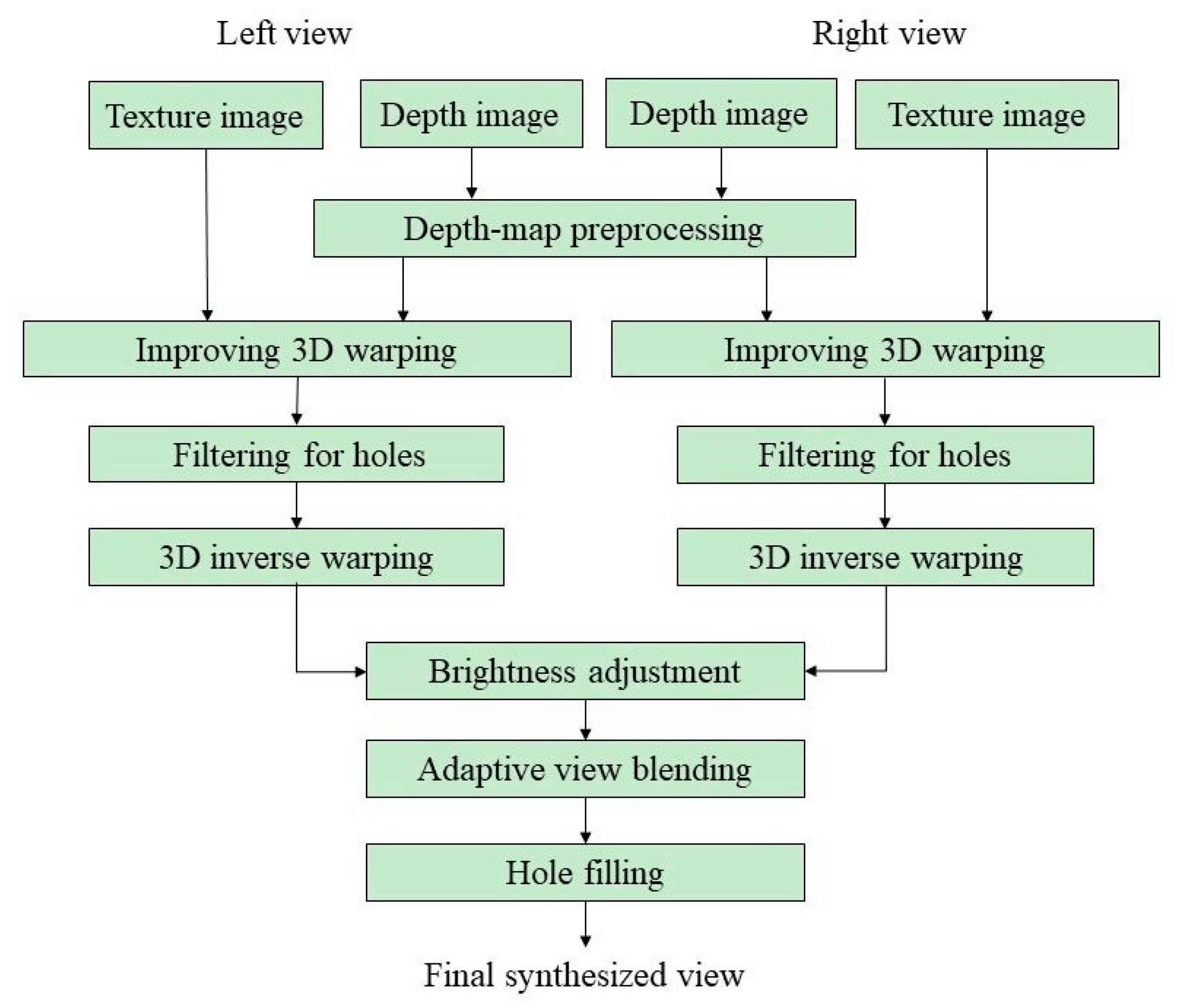
In this section, we describe the proposed method, including depth map preprocessing, improving 3D warping, filtering, 3D inverse warping, brightness adjustment, adaptive blending of virtual views, and hole filling. The flowchart of the proposed system is illustrated in Figure 4. The details of the procedures are described in the following subsections.

3.1. Depth Map Preprocessing

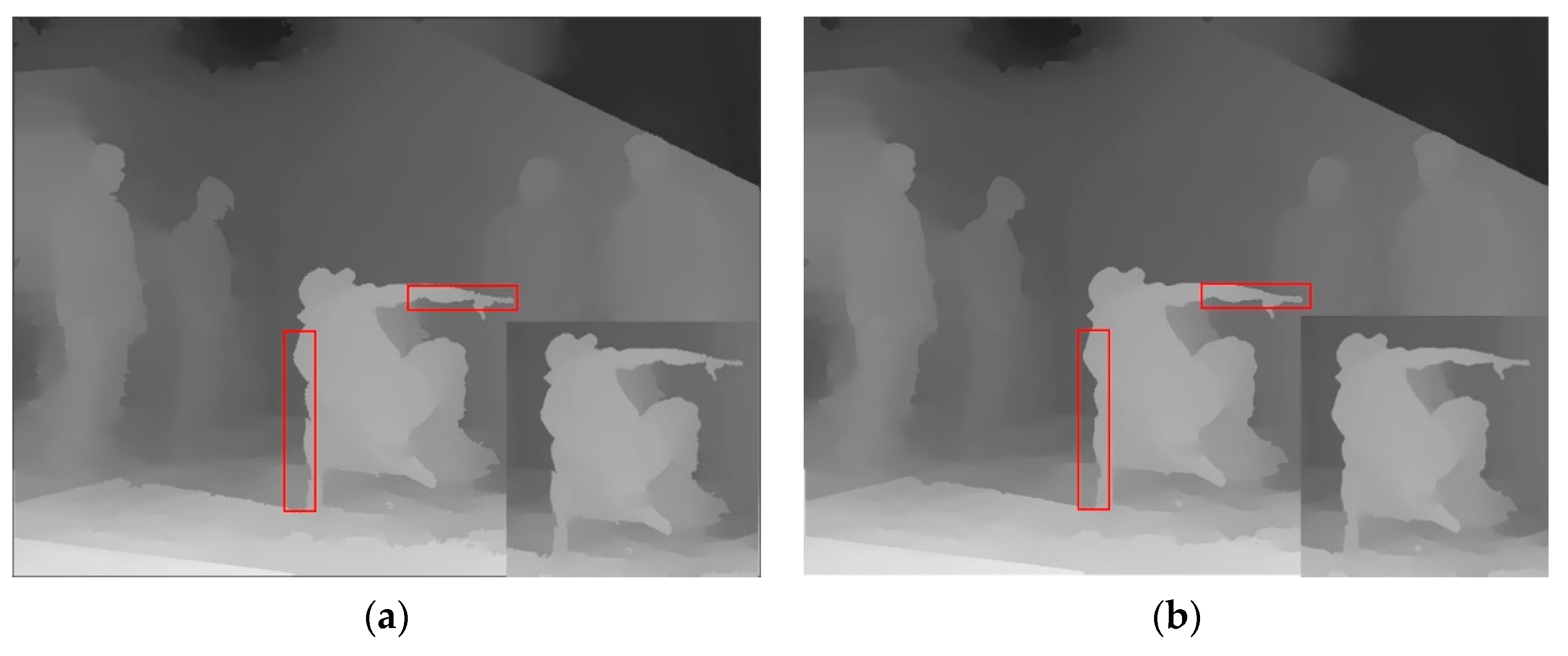
Generally, the depth map can be generated using a depth camera system, computer graphics methods, or mathematical calculation using a depth estimation algorithm. Although depth estimated from a depth camera system is the most popular approach, a depth camera is costly and the images generated by computer graphics computation cannot illustrate real scenes. Hence, calculating depth values mathematically is currently adopted. However, the depth values estimated by mathematical calculations tend to produce erroneous values in certain regions in the image, or yield inconsistent values in various regions across spatial or temporal neighbors. Hence, we first performed a closing morphologic procedure twice and then used a median filter of size 5 × 5 to preprocess the initial depth map. Based on these strategies, the initial depth map can retain the native information well and efficiently reduce hole generation in the subsequent 3D warping procedure. Figure 5 shows the results of the depth map preprocessing.

3.2. Improving 3D Warping Process in DIBR

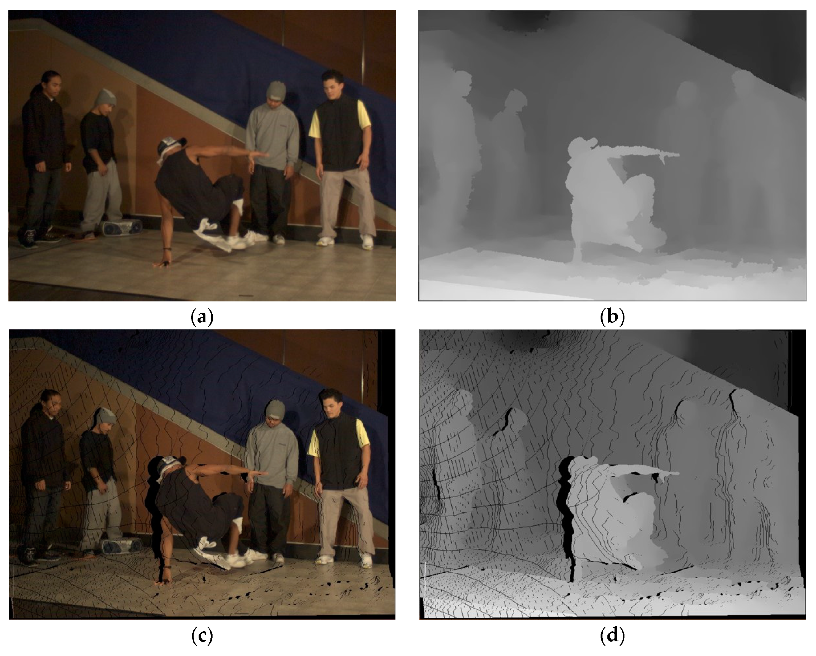
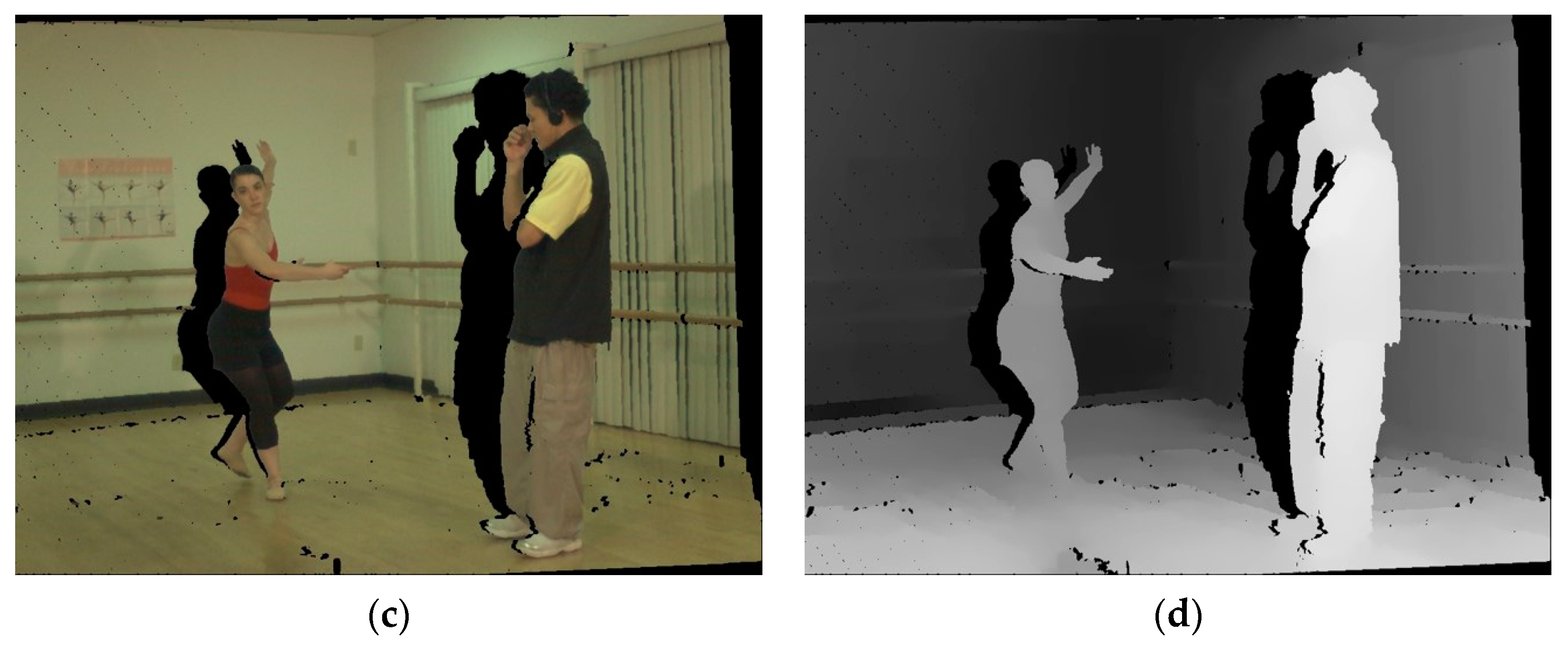
Traditional depth-based 3D warping typically generates erroneous points, such as those illustrated as black points in Figure 6. This is because many pixels of the texture image are produced after performing a backprojection from the 2D reference view to the 3D world coordinates system, and the reprojection of backprojection from the 3D world coordinates system to a 2D virtual view is projected to the same location in the virtual view, because of round-off coordinates. These erroneous points (called holes) will seriously affect the visual quality of video sequences and cause inconsistent color values, presented as false black-contours in the synthesized view. To reduce the generation of holes, we propose a novel strategy to improve the traditional 3D warping; our proposed novel 3D warping process can significantly reduce the number of holes in each sequence.
As mentioned above, the 3D warping process requires the camera’s intrinsic and extrinsic matrices provided by [33] to transform a 2D reference view plane to 3D world coordinates, and from 3D world coordinates to a 2D virtual view plane. First, let ( s , t ) be the pixel coordinates in the 2D reference view plane; they are then backprojected into the 3D world coordinates ( W x , W y , W z ) using (5). Equation (5) is rewritten as
( W x W y W z ) = R r e f 1 K r e f 1 ( s t 1 ) d ( s , t ) R r e f 1 t r e f ,
where R r e f , K r e f , and t r e f denote the rotation matrix of size 3 × 3 , the camera intrinsic matrix of size 3 × 3 , and the translation matrix of size 3 × 1 , respectively. d ( s , t ) denotes the depth value corresponding to the coordinates ( s , t ) . Next, we perform the second projection from the 3D world coordinates ( W x , W y , W z ) to the 2D virtual view coordinates ( U r , V r ) using (8) and (9).
( V u V v V w ) = K v i r R v i r ( W x W y W z ) + K v i r t v i r
U r = r o u n d ( V u V w ) , V r = r o u n d ( V v V w )
where K v i r , R v i r , t v i r denote the camera intrinsic matrix of size 3 × 3 , the rotation matrix of size 3 × 3 , and the translation matrix of size 3 × 1 in the virtual view. Owing to the round-off errors of the coordinates by (9), this operation will result in hole generation. This is because several points in the 2D reference view are projected into the same location and they lose the reliable texture data (color information) for filling. These points that are projected into the same location using the traditional 3D warping tend to have overlapping values, or erroneous values, or vain values, thus, degrading the quality of video sequences. Hence, we propose a novel method to improve the traditional 3D warping process further. The improved strategy is described in the following.
First, given a pixel coordinates ( s , t ) in the 2D reference view plane (I) followed by calculations using (7)–(9), we decide the reliable mapping coordinates according to the following condition, to change the coordinates in the virtual view. The decision condition is expressed as
( T u , T v ) = arg min   d ( s , t ) ( s , t ) I ,   if   s = U r ,   t = V r .
When several points that belong to the I are projected into the same location in the virtual view, the point with the smallest depth value will be selected as the virtual view coordinates. According to the depth map characteristics, the depth value of a pixel in the depth map, represented by an 8-bit grayscale in the range [0, 255], defines a distance along the Z axis. The “0” represents the most distant depth value in the depth map, while the “255” represents the closest depth value. Hence, the larger the depth value, the nearer the camera is. In other words, the FG has the larger depth value. In contrast to the FG, the BG represents the smaller depth value. Hence, we selected the smallest depth value in (10), because holes are typically generated from the FG region. Hence, the advantages of selecting the smallest depth value are as follows: (1) the number of holes after projection can be reduced, and (2) the reprojection processes and the BG region in the 2D reference view can finish efficiently prior to the projection process, to obtain the corresponding coordinates in the virtual view. Next, after computing (10), if ( U r , V r ) ( T u , T v ) , the traditional 3D warping method will be adopted to achieve the projection. If ( U r , V r ) = ( T u , T v ) , we will further modify the virtual coordinates ( T v , T v ) according to the relative depth value, color information of ( T v , T v ) , and ( U r , V r ) . The modified method is expressed as
( T u u p d a t e , T v u p d a t e ) = { ( T u , T v ) , if   d ( T u , T v ) > d ( U r , V r ) , arg min ( c 1 ( T u , T v ) , c 2 ( U r , V r ) ) , if   d ( T u , T v ) = d ( U r , V r ) , N U L L otherwise ,
where c 1 ( T u , T v ) = ( r c 1 , g c 1 , b c 1 ) , c 2 ( U r , V r ) = ( r c 2 , g c 2 , b c 2 ) , ( r , g , b ) denote the red, green, and blue components of the color space, respectively; NULL denotes the hole; denotes the norm. Finally, based on (11), we can obtain the updated projected coordinates ( T u u p d a t e , T v u p d a t e ) in the virtual view. The updated coordinates ( T u u p d a t e , T v u p d a t e ) will be backprojected into the 3D world coordinates to obtain the update coordinates ( W x , W y , W z ) using (12).
( W x W y W z ) = R r e f 1 K r e f 1 ( T u u p d a t e T v u p d a t e 1 ) d ( T u update , T v u p d a t e ) R r e f 1 t r e f .
The updated 3D world point ( W x , W y , W z ) is substituted into (8), and (8) is rewritten as
( T u update T v update 1 ) = K v i r R v i r ( W x W y W z ) + K v i r t v i r ,
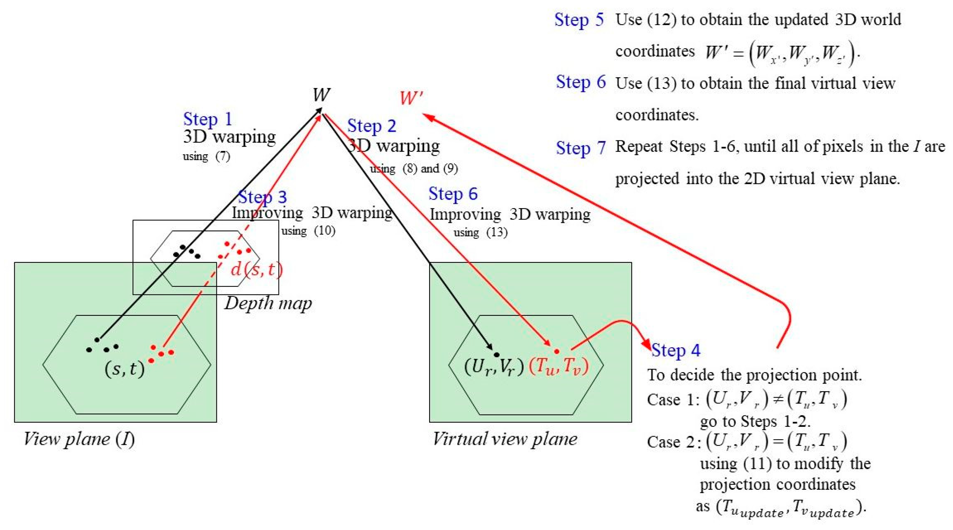
where ( T u u p d a t e , T v u p d a t e ) is the final virtual view coordinates corresponding to the pixel coordinates ( s , t ) in the 2D reference view. We repeat the procedures above until all pixels in the 2D reference view plane have undergone the projection operation into the 2D virtual view plane. Figure 7 illustrates the profile of our proposed improved 3D warping process in DIBR.
A summary of how the 3D warping procedures are improved is as follows.
Input: A series of reference views, the corresponding depth maps, and the camera’s parameters provided by [33].
Step (1) Given a pixel location ( s , t ) in the 2D reference view plane (I), perform a backprojection from the 2D reference view plane to the 3D world coordinates ( W x , W y , W z ) using (7).
Step (2) Find the 2D virtual view coordinates ( U r , V r ) using (8) and (9).
Step (3) Verify whether the points in I are mapped into the same location in the virtual view plane. If yes, the projected virtual point will be changed using (10).
Step (4) Decide the changed virtual point in the virtual view plane according to the result of Step 3; If ( U r , V r ) ( T u , T v ) , proceed to Steps 1–2. If ( U r , V r ) = ( T u , T v ) , the changed virtual point will be further updated using (11), and proceed to Step 5.
Step (5) Compute the updated 3D world coordinates using (12).
Step (6) Use the updated 3D world point to obtain the final virtual view coordinates based on (13).
Step (7) Repeat Steps 1–6, until all pixels in I have been processed.
The two side views (left and right) shown in Figure 4 are used individually for improving the 3D warping process, to obtain the corresponding virtual views.

3.3. Filtering for Holes

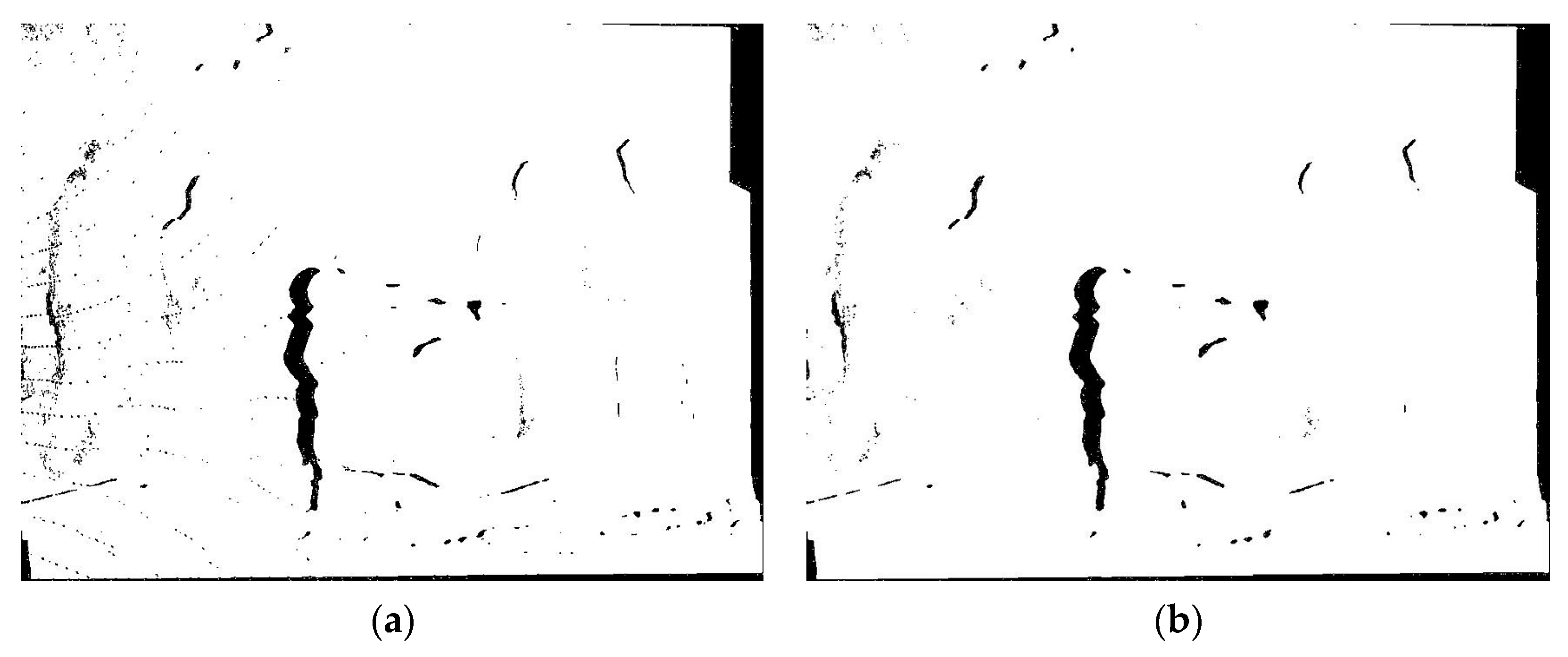
Owing to the drawback of the depth map, the depth map has been preprocessed, as described in the previous section. After improving the 3D warping process using the preprocessed depth map, holes still appear in the virtual view. If a median filter is used directly in a depth map with holes using the improved 3D warping process, the resulting image will be extremely smooth and vague. To avoid this, we used a median filter of window size 3 × 3 in the holes, as expressed in (14).
H o l e s i , j = m e d i a n ( Y i , j ) , Y i , j Hole   region ,
where Y i , j denotes the depth value at the coordinates ( i , j ) as a center point around a 3 × 3 window size.
This process not only modifies the smooth and vague images, but also decreases the computational time of the subsequent procedures. If this procedure is removed, it will cause a poor image quality and increase the execution time of the system. Figure 8 illustrates the binary results of filtering the entire depth map and filtering the holes.

3.4. 3D Inverse Warping Process

The DIBR technique is transferred from the neighboring view to the virtual view, which is known as forward mapping. However, in forward mapping, cracks might be transmitted into the virtual view, owing to the round-off errors and inaccurate depth values. To circumvent the usual problems associated with the forward mapping rendering techniques (cracks), an inverse warping rendering technique can be used to correct the cracks. This technique is simple, and accurately resamples synthetic pixels [32]. Hence, we adopted the inverse warping rendering technique to remove the usual problems associated with rendering, using forward mapping and further improved the view quality.
First, for each pixel in the virtual view plane and the corresponding depth map, ( R v , K v ) corresponds to the rotation parameter and the intrinsic parameter of the virtual camera; a 3D world point ( W 2 x , W 2 y , W 2 z ) is calculated using backprojection, expressed as
( W 2 x W 2 y W 2 z ) = C v + λ R v 1 K v 1 d v ,
where λ is defined as
λ = W 2 z C v z r 3   with   ( r 1 r 2 r 3 ) = R v 1 K v 1 d v   and   C v = ( C v x C v y C v z ) .
Here, the depth value W 2 z is defined by the pixel value at coordinate d v in the depth map of the virtual view; in our system, we used the k value obtained using (2) instead of λ . Next, the calculated 3D world point ( W 2 x , W 2 y , W 2 z ) is projected into the reference texture view plane using (17).
λ p 1 = K r e f R r e f ( W 2 x W 2 y W 2 z ) + K r e f t r e f ,
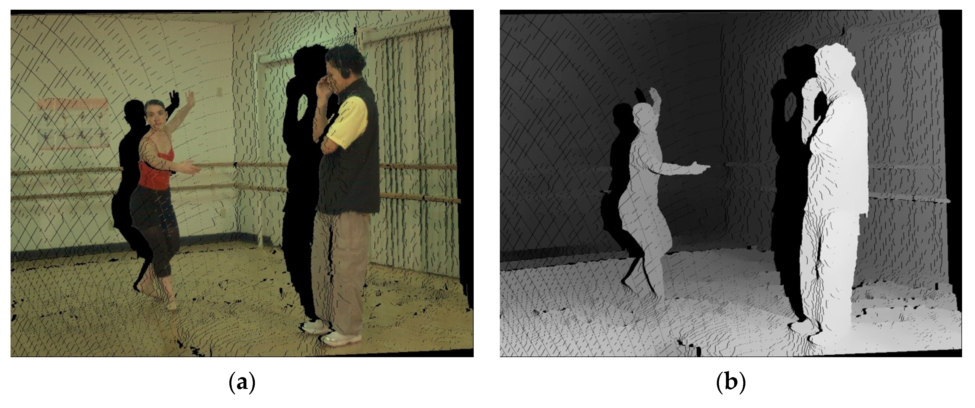
where p 1 = ( s r , t r , 1 ) T refers to the coordinates of a pixel in the reference view plane. K r e f refers to the camera intrinsic parameter of the reference view; R r e f and t r e f represent the camera extrinsic parameters of the reference view. The color of a pixel in the virtual view plane can be interpolated from the pixels surrounding p 1 in the reference view plane. Based on (17), the possible holes in the virtual view plane can be found in the corresponding pixel values in the reference view plane, and can be padded based on inverse warping blending. Figure 9 illustrates the results of 3D inverse warping rendering.

3.5. Brightness Adjustment

After performing the procedures above, we obtained two virtual views corresponding to two side views (left side and right side). The disocclusions are not visible in the main reference view (left-side view), but they are visible in the virtual view. Hence, we can recover these disocclusions by the reference view on the other side of the virtual view, which is called the auxiliary reference view. That is, the auxiliary reference view is only used to fill the disocclusions. Blending refers to combining two virtual views warped from two side views into a synthesized virtual view. Additionally, the brightness of two reference views is typically different; therefore, two virtual views will display inconsistent brightness. Hence, if we directly synthesize these two virtual views without brightness adjustment, the synthesized view will display inconsistent brightness and discontinuous colors. Hence, we used a strategy based on the method in [8] for brightness adjustment, to improve these problems.
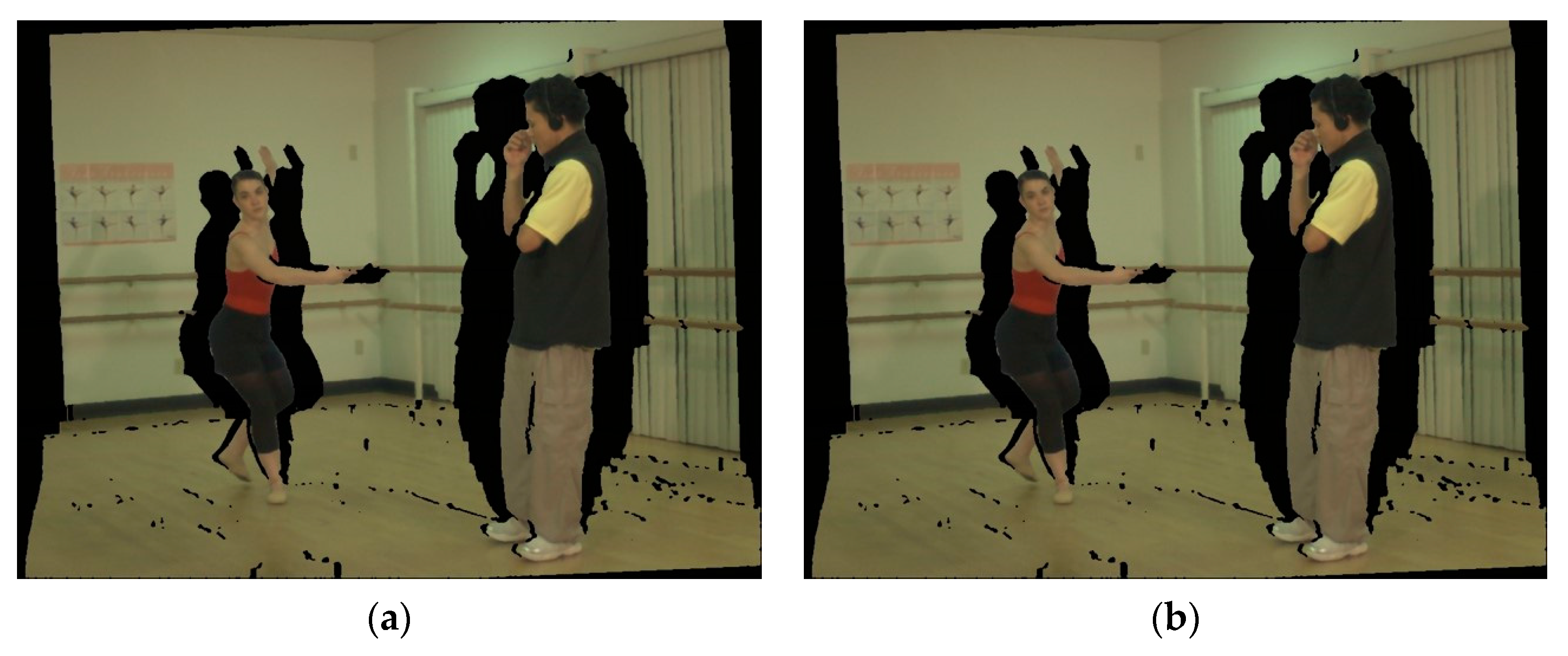
First, two side reference views (left-side view, right-side view) are warped to the corresponding virtual views based on DIBR. The left-side reference view is called the main view; the other side reference view is called the auxiliary view. V m a i n and V a u x represent the main virtual view warped from the main view and the auxiliary virtual view warped from the auxiliary view, respectively. To obtain virtual views with the same number of holes warped from the main and auxiliary views, we created two virtual views: V m a i n involved with V a u x is referred as V m a i n ; V a u x involved with V m a i n is referred as V a u x , as shown in Figure 10. Next, the brightness of the auxiliary virtual view is adjusted based on the brightness of the main view. The V a u x , V m a i n , and V a u x are converted into the hue, saturation, value (HSV) color space. The component V represents the brightness. We then calculate the brightness ratio for each pixel of the nonhole regions in V m a i n and V a u x . The ratio of the brightness component is computed as follows:
B r ( i , j ) = V m a i n ( i , j ) V a u x ( i , j ) ,   ( i , j ) non - hole   regions ,
B r M e a n = 1 n B r ( i , j ) ,
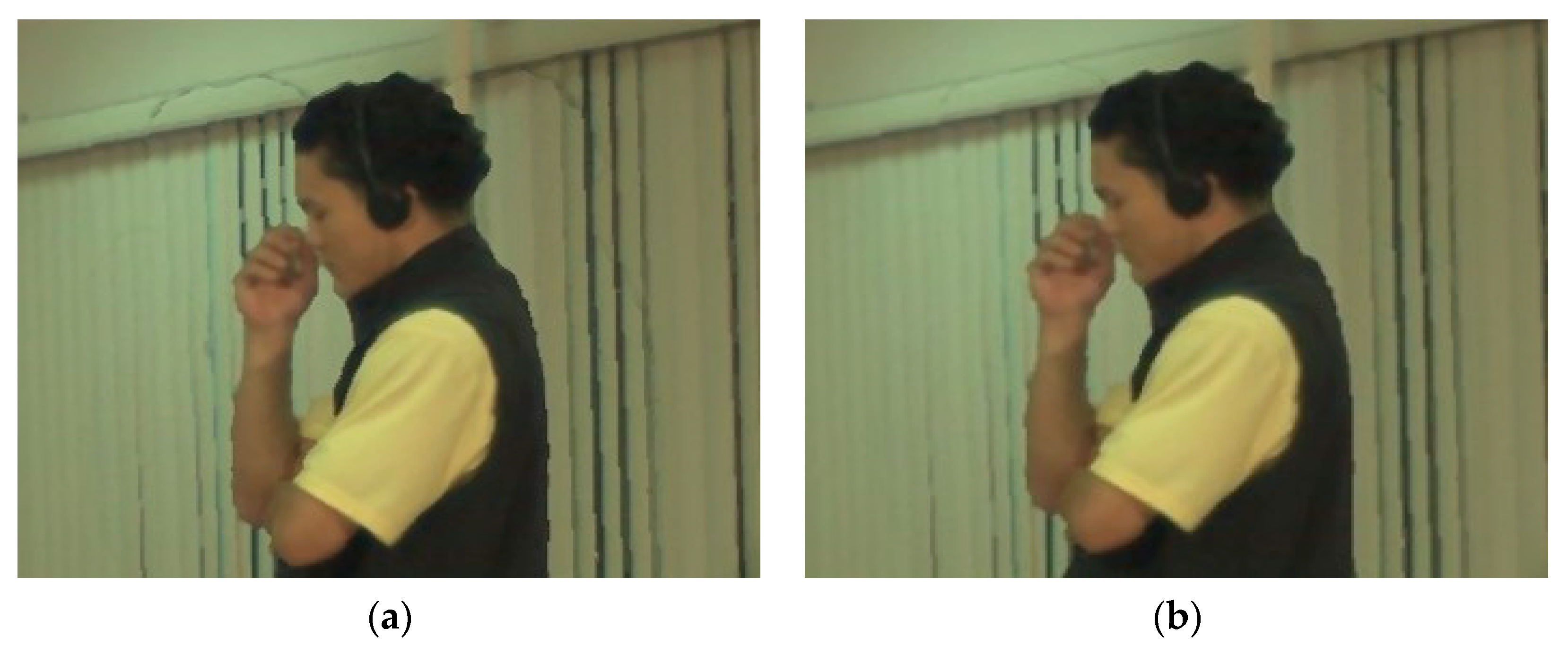
where n denotes the number of nonhole pixels; ( i , j ) represents the coordinates of a pixel belonging to nonhole regions; B r M e a n is the mean ratio used for adjusting the brightness of the auxiliary virtual view in the HSV color space. Finally, the adjusted auxiliary virtual view is converted into the red, green, blue (RGB) color space. Thus, the brightness of the virtual view warped from the auxiliary view has been adjusted to match that of the main view, as shown in Figure 11. Figure 11 illustrates the results of the brightness adjustment. From Figure 11, after adjusting the brightness, the head surrounding is improved and the ghost is reduced. Hence, in order to reduce the ghost generation and maintain the vision quality for viewing, brightness adjustment is a necessary step.

3.6. Adaptive Blending of Virtual Views

After performing the brightness adjustment, two virtual views warped from the left-side and the right-side views individually can represent the consistent brightness based on the brightness of the main reference view. Subsequently, to obtain a synthesized virtual view, two virtual views are blended into the synthesized virtual view. In most studies, the simplest view blending using a weighted sum of two images is performed to synthesize 3D warped views to a virtual view, expressed as
I v ( u , v ) = ( 1 α ) I L ( u , v ) + α I R ( u , v ) ,
where I L and I R are the left-side and right-side warped reference texture views corresponding to the coordinates ( u , v ) , respectively; I v is the blended view; α is the position-dependent interpolation parameter. However, this common blending can yield inconsistent pixel values, because of inaccurate camera parameters, inconsistent depth values, or the warping of round-off errors. These inconsistent pixels from both views can result in warped images, producing artifacts or jagged edges. To avoid this problem, we adopted adaptive blending to perform view blending based on the method in [22]. Herein, the main virtual view is defined as a virtual view warped from the left-side view, and an auxiliary virtual view is the warped view from the right-side view. The adaptive blending is expressed as
I v ( u , v ) = α I A ( u , v ) + ( 1 α ) I B ( u , v ) ,
where I A and I B denote the main virtual view and the auxiliary virtual view after brightness adjustment, respectively. α is 1 for a nonhole region and 0 for the hole pixels in I A depending on the selected viewpoint. Based on (21), most regions of the blended view are from the main virtual view, and some holes in the blended view are filled from the auxiliary virtual view.

3.7. Hole Filling

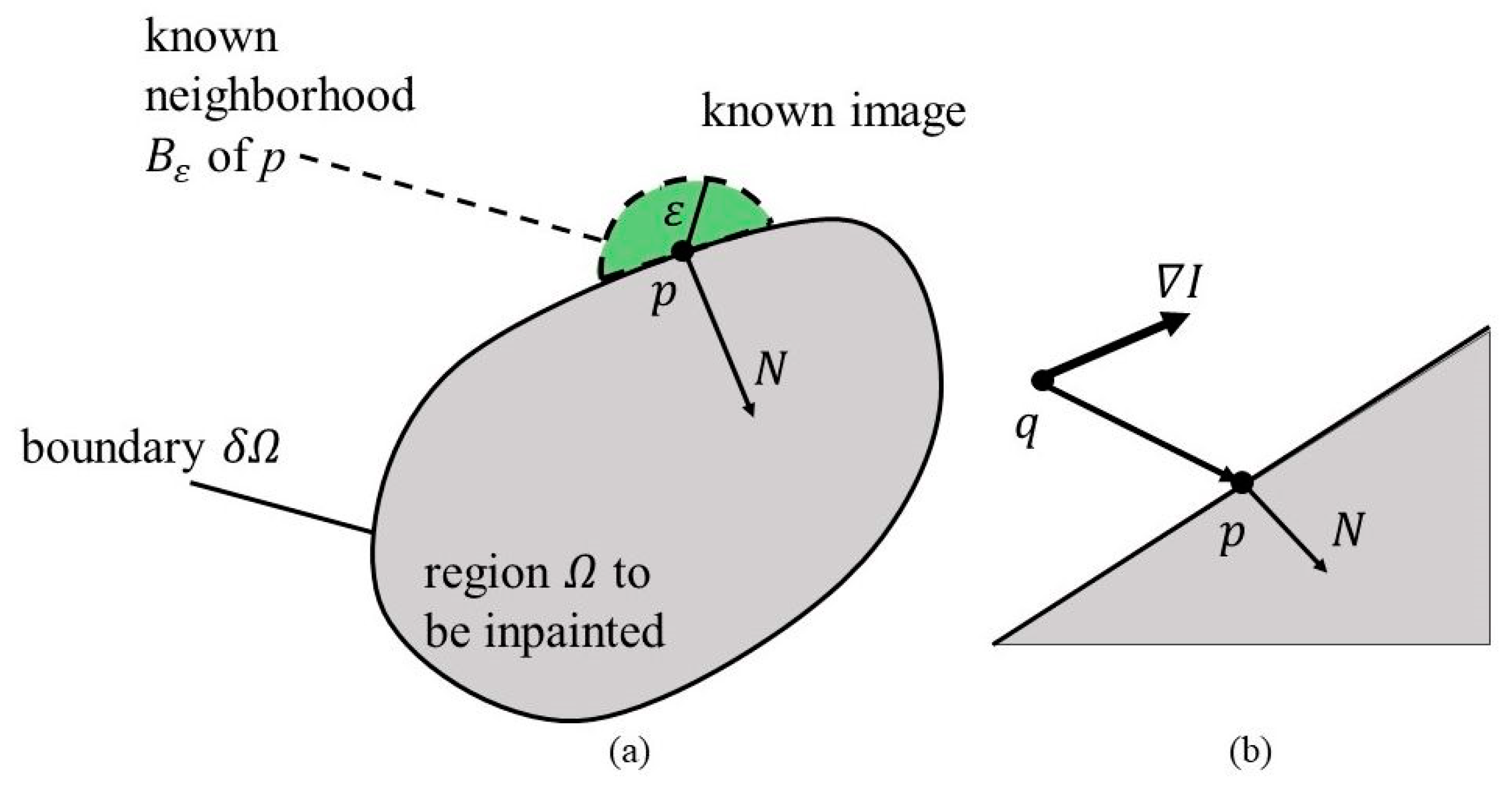
Most of the holes are filled after adaptive blending is performed. However, a few holes still exist in the blended virtual view. The remaining holes in the synthesized view are the disocclusion regions due to the reprojected process; they are generally located in the BG areas and occur at the FG boundaries, or appear because of inaccurate depth. To fill the remaining holes, an exemplar-based inpainting method [17] is typically adopted. However, this exemplar-based method is highly time-consuming, because it is a global-based search strategy that searches for the best patch to repair. In the 3DTV FVV scheme, computational time is a serious problem. Hence, we used a sample method combined with the FMM algorithm [18] to fill the holes quickly, by modifying the boundary condition in the inpainting. Briefly, The FMM procedures are as follows: the region Ω to be inpainted and its boundary δ Ω are defined; the pixel p belonging to Ω would be inpainted by its neighboring region B ε ( p ) of size ε , as shown in Figure 12a. Herein, we set ε to 3. Assume that a gray value image is considered, and color images are the following extension. First, to compute an approximation I q ( p ) of the image in point p, given the image I ( q ) and its gradient value I ( q ) of q point (Figure 12b).
I q ( p ) = I ( q ) + I ( q ) ( p q )
Next, inpaint point p as a function of all points q in B ε ( p ) , by summing the estimates of all points q, weighted by a weighting function w ( p , q ) .
I ( p ) = q B ε ( p ) w ( p , q ) [ I ( q ) + I ( q ) ( p q ) ] q B ε ( p ) w ( p , q ) .
The weighting function is defined as a product of three factors: w ( p , q ) = d i r ( p , q ) · d s t ( p , q ) · l e v ( p , q ) .
d i r ( p , q ) = p q p q · N ( p ) ,
d s t ( p , q ) = d 0 2 p q 2 ,
l e v ( p , q ) = T 0 1 + | T ( p ) T ( q ) | .
The directional component d i r ( p , q ) ensures that the contribution of the pixels is close to the normal direction N = (gradient). The geometric distance component d s t ( p , q ) decreases the contribution of the pixels geometrically farther from p. The level set distance component l e v ( p , q ) ensures that pixels close to the contour through p contribute more than the farther pixels; d 0 and T 0 are the interpixel distances, to be set as 1. T ( p ) is the distance between the point p and the initial inpainting boundary δ Ω .
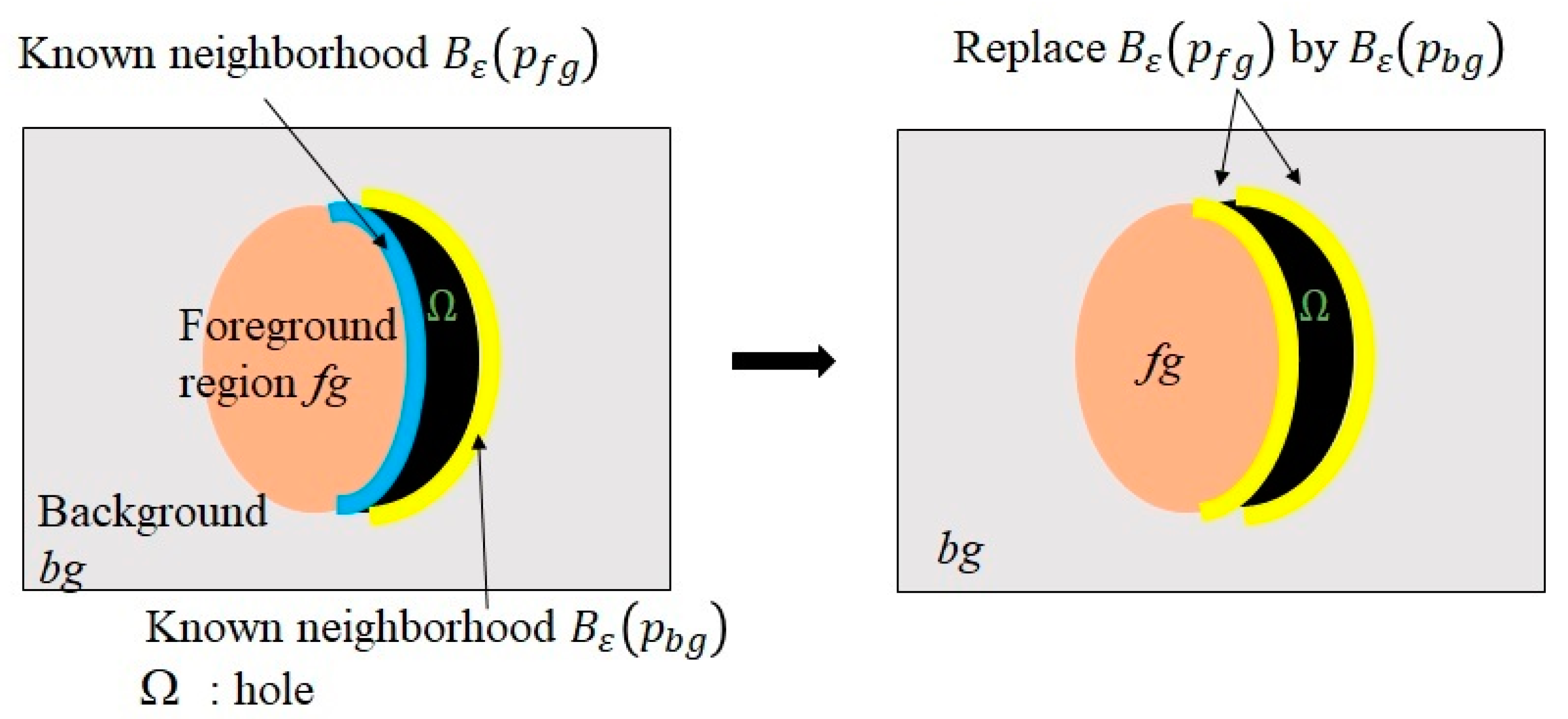
Additionally, the inpainting concept should be changed to be applied to hole filling in view synthesis, because the boundary of the holes may belong to both the FG and BG. Hence, we modified the boundary information of the hole in the inpainting based on the method presented in [15]. We changed the boundary region with the FG on the hole to the corresponding BG region located on the opposite side. To distinguish between the FG and BG, we adopted the relative magnitude of the depth values between two points that were horizontally opposite to each other on the hole boundary. The boundary point with the larger depth value that was regarded as belonging to the FG will be replaced with the boundary point with the smaller depth value that was regarded as belonging to the BG. The interval of the boundary region was the same as ε and set as 3 pixels. Figure 13 shows an example of the boundary region replacement for the hole. The replacement mechanism is represented by
p f g δ Ω f g p b g δ Ω b g ,
B ε ( f g ) B ε ( b g ) ,
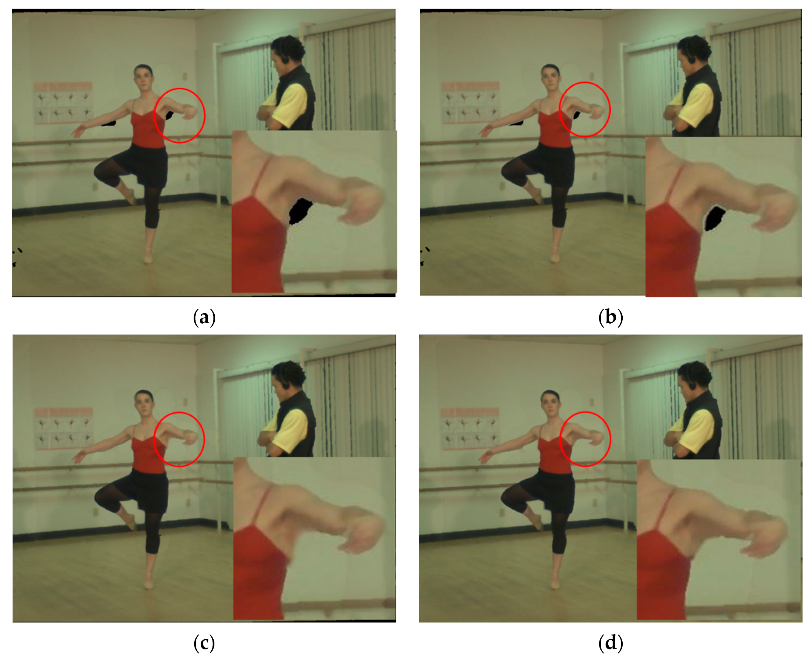
where f g and b g denote the FG and the BG, respectively. Figure 14 shows the inpainting result. Thus, the improved boundary strategy on hole filling will efficiently reduce the disturbance of the FG under inpainting and accelerate the inpainting computational time.

4. Experimental Results and Discussion

To verify the performance of the proposed hole filling method for 3D virtual view synthesis, the experimental results are compared with those of Chang et al. [21], Cho et al. [19], Luo and Zhu [26], and Oliveira et al. [27]

4.1. Experimental Setup and Datasets

The experimental data were “Ballet” and “Breakdancers” video sequences of size 1024 × 768 derived from Microsoft research [33], and each video sequence included 100 images. Two neighboring side views (left-side view and right side view) were used to render a virtual view. In this study, the virtual view was at the Camera 4 location; thus, Cameras 3 and 5 that were placed at the left and right were used as the two side reference views. The experiments were implemented in Microsoft Visual Studio C++2017, on an Intel ® core i7-4790@ 3.6 GHz computer with 16 GB of RAM.

4.2. Performance Evaluation

For performance evaluation, we used the peak signal-to-noise ratio (PSNR) and structural similarity (SSIM) [34], to demonstrate our proposed method. The PSNR and mean square error (MSE) are expressed as
P S N R = 10 log S max 2 M S E ,
M S E = 1 h × w i = 0 h 1 j = 0 w 1 | f ( i , j ) f ( i , j ) | 2 ,
where f ( i , j ) and f ( i , j ) denote the original image (ground truth) for Camera 4 and the synthesized virtual view corresponding to the coordinates (i, j), respectively. w and h denote the width and height of the image, respectively. S max is 255 for a gray-level image. The higher the PSNR value, the closer the synthesized view and ground truth are to each other. Similarly, the SSIM value is closer to 1, and both the synthesized view and ground truth are more similar to each other.

4.3. Results

The experimental results are presented and discussed in the following sections.

4.3.1. Comparison of Traditional 3D Warping and Improved 3D Warping

According to our proposed method, we improved the traditional 3D warping method to decrease the number of error matching points. That is, the hole numbers can be reduced efficiently. We computed the number of holes using traditional 3D warping and improved 3D warping to yield the performance shown in Table 1.
From Table 1, it is clear that the improved 3D warping method decreased the number of hole pixels by more than 1.9% in both Ballet and Breakdancers. That is, the fewer the number of holes, the shorter the execution time.

4.3.2. Comparison of Execution Time

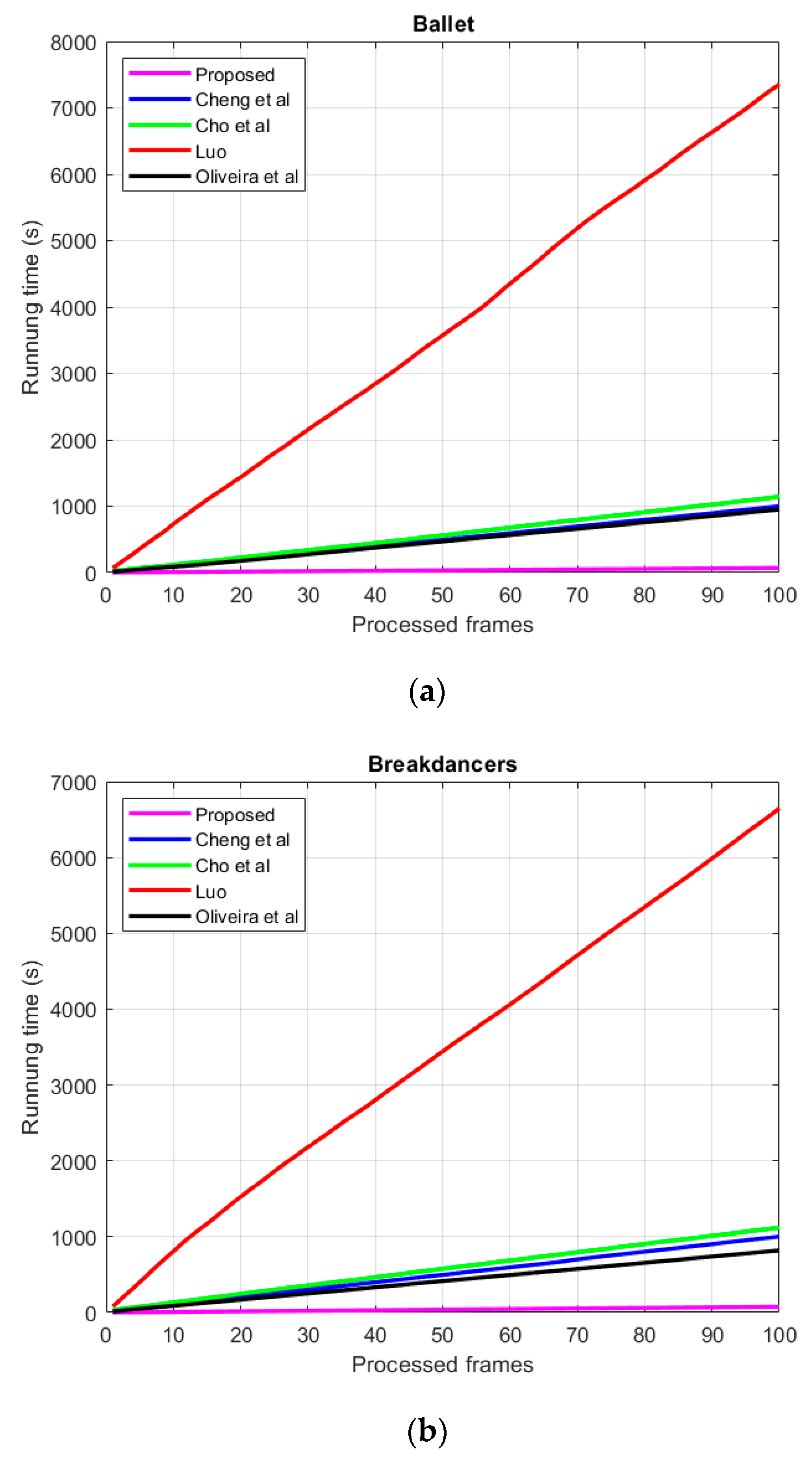
In this section, the execution times are illustrated for both datasets. The execution times in seconds are illustrated in Table 2. Figure 15 shows the cumulative execution times corresponding to the number of frames compared with our proposed method and the methods of Chang et al. [21], Cho et al. [19], Luo and Zhu [26], and Oliveira et al. [27] As shown in Table 2, the execution speed of our proposed approach is faster than that of the other methods. The average execution time of our proposed method for Ballet is only 0.69 s per frame. In contrast to our proposed method, the other methods require more time on both datasets, especially that of Luo [20]. The hole repair strategy in the synthesized virtual view for the compared methods is to improve the exemplar-based inpainting method [17]. The inpainting method by [17] is highly time-consuming, because a global-based method is used to search for the matching patch. Hence, the methods in [19,21,27] require at least 9.49 s. In Luo’s method, FG objects are first removed and then holes are repaired based on [17]. The average execution time for Luo’s method exceeds 66.5 s, which is significantly higher than our proposed method.

4.3.3. Evaluation of Synthesized Virtual View

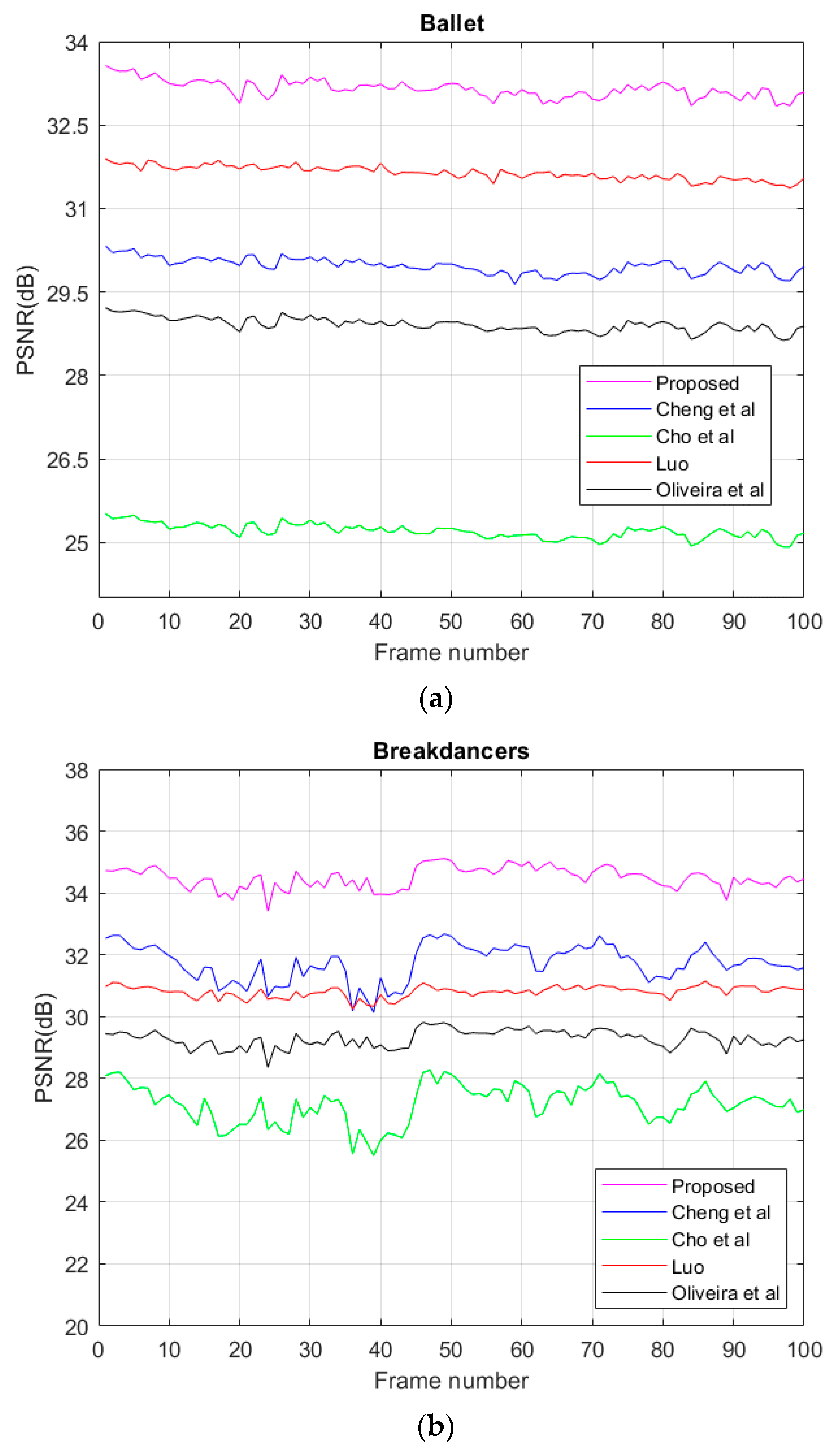
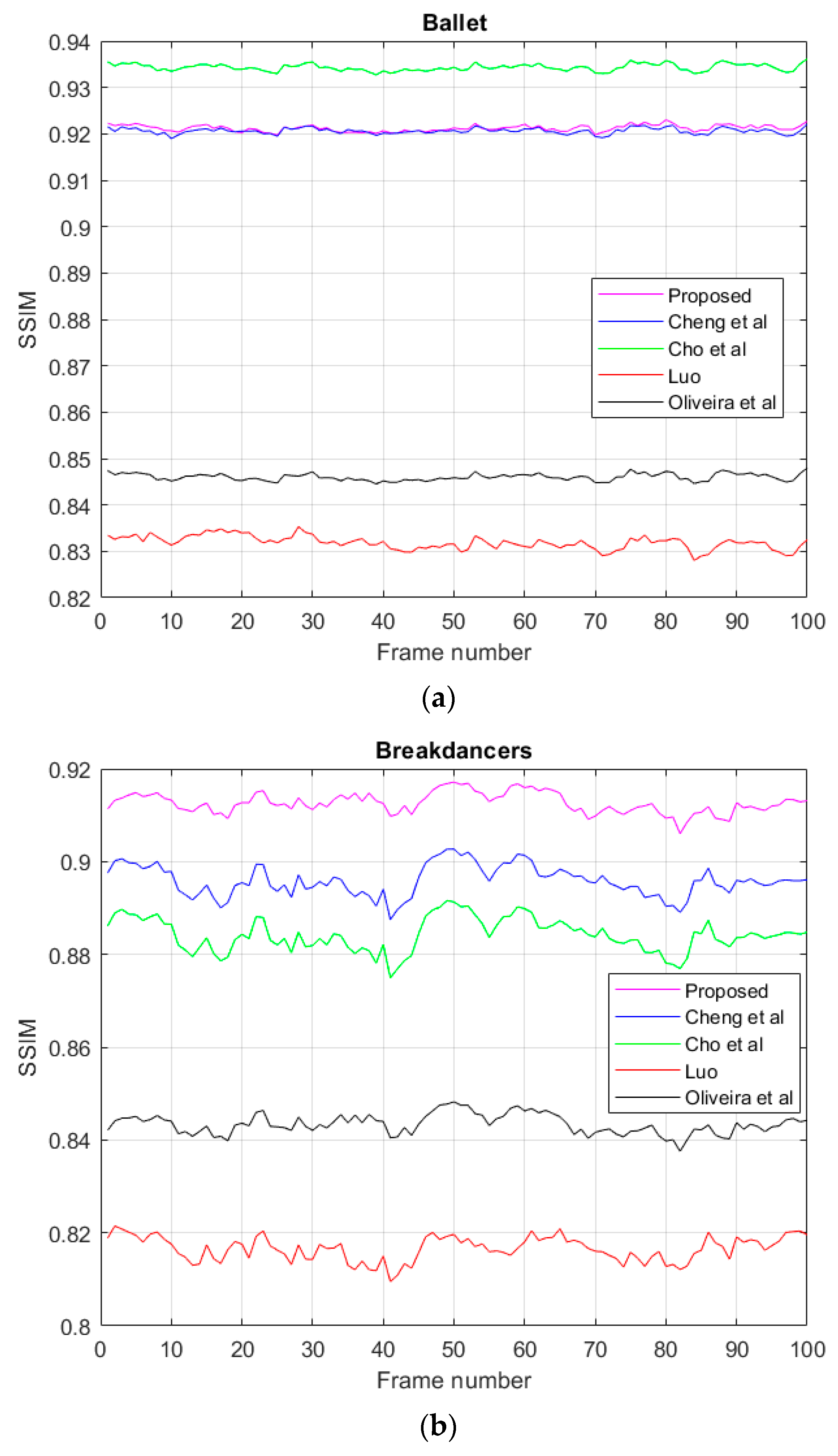
In our experiments, we used the average PSNR value (Ave_PSNR) and SSIM value (Ave_SSIM) to evaluate the synthesized virtual view obtained by our proposed method. Table 3 shows the average PSNR and SSIM values. Figure 16 and Figure 17 illustrate the detailed results for the PSNR value and SSIM value per frame, respectively. From Table 3, it is clear that the average PSNR value for both the Ballet and Breakdancers datasets is superior to those of other methods. For the Ballet dataset, the SSIM of our proposed method was slightly lower than that of Cho et al.’s [19]. This was because the hole filling based on Criminisi et al.’s method [17] increased the BG term into the priority computation to prevent FG propagation; thus, the BG regions were inpainted prior to the FG regions or boundary regions. The average SSIM value increased only by 0.013. However, in the Breakdancers dataset, the average SSIM value was less than that of our proposed method. In addition, the average SSIM value obtained from Chang et al.’s [21] and our proposed method on the Ballet dataset was almost the same. However, the execution time of our proposed method, as shown in Table 2, was 14 times faster than that of Chang et al.’s [21] and Cho et al.’s [19] method. For the Breakdancers dataset, the average SSIM value obtained by our proposed method was higher than those using other methods.
In addition, comparing the datasets Ballet and Breakdancers for our proposed method, as shown in Table 3, the average PSNR value on Breakdancers was greater than the average PSNR value on Ballet. This was because the camera parameters and depth map quality of the different datasets provided by Microsoft research were distinctly different. These factors affected the performance evaluation. From Table 3, we verified that the camera parameters and depth map quality on Breakdancers were better than those on Ballet.
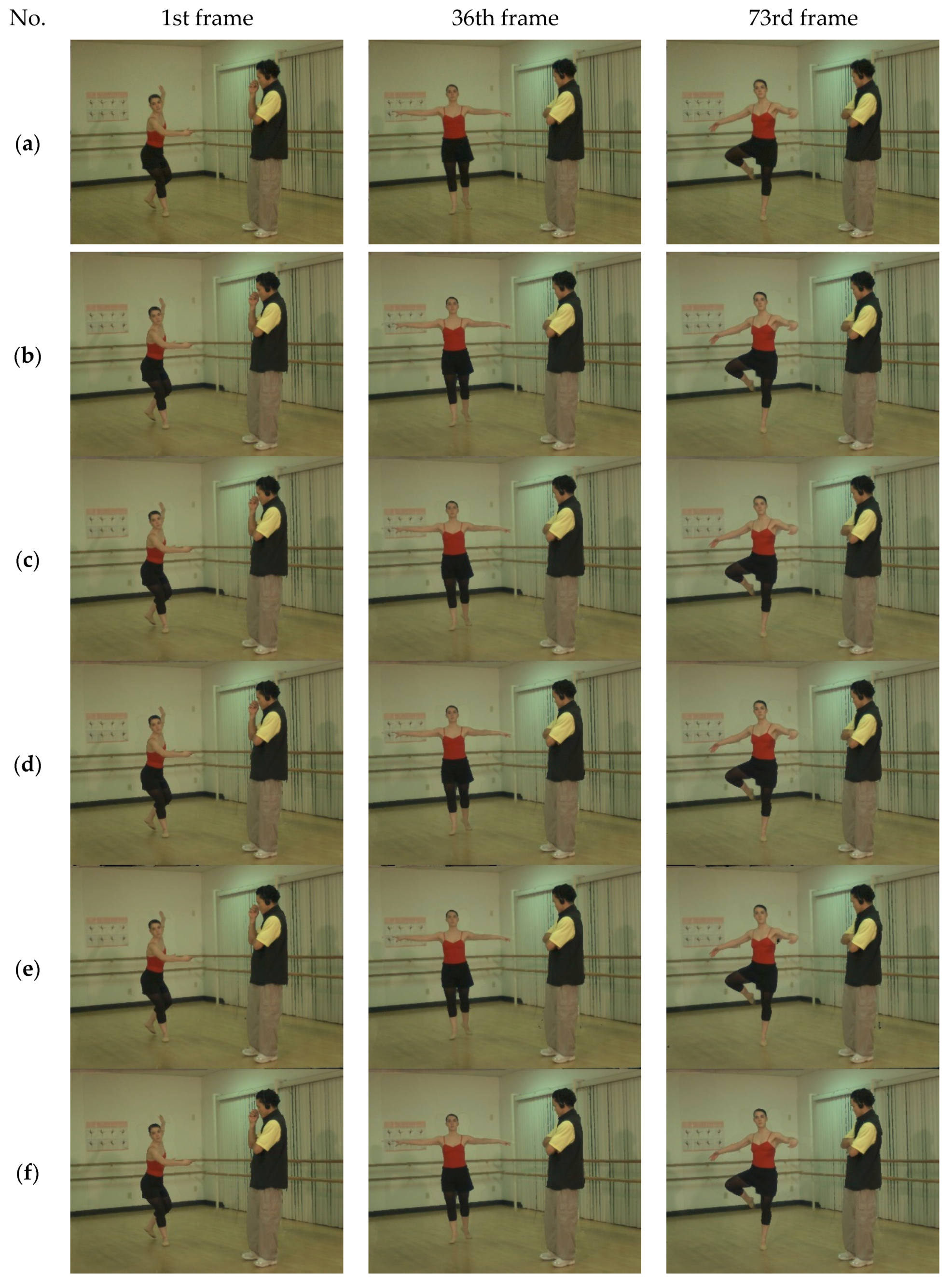
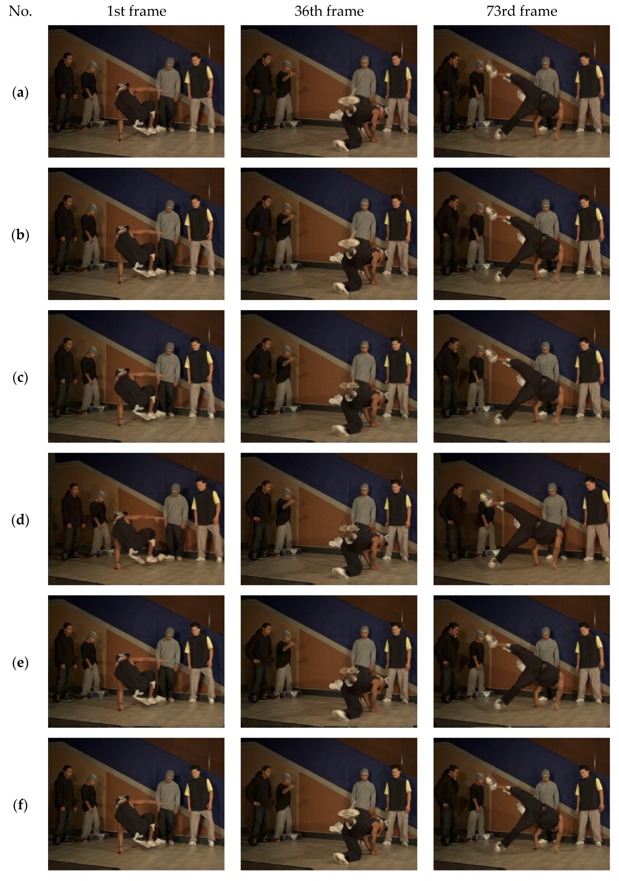
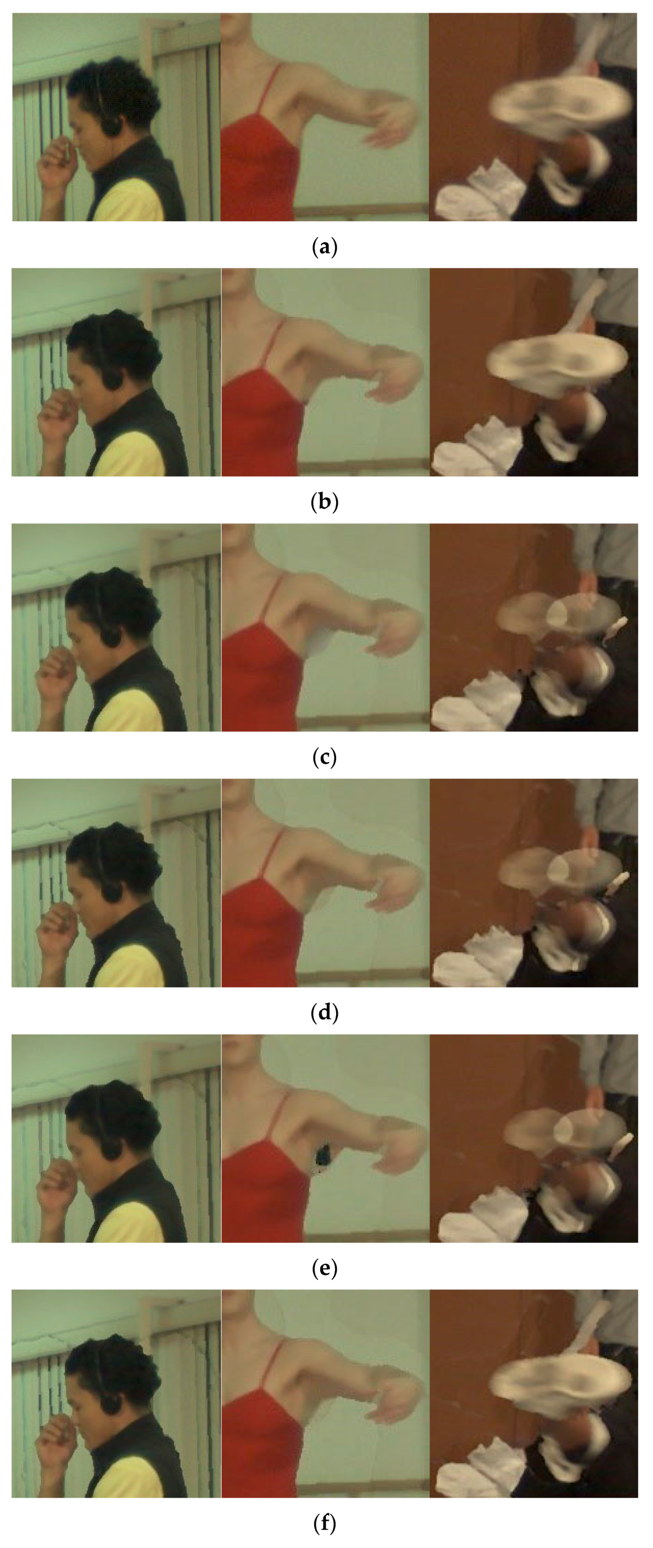
Figure 18 and Figure 19 show the visual quality of the synthesized virtual view compared with those of Chang et al.’s [21], Cho et al.’s [19], Luo and Zhu’s [26], and Oliveira et al.’s [27]. As shown in Figure 18 and Figure 19, the hole filling for the synthesized virtual view using our proposed method presented better quality. Figure 20 shows an enlarged synthesized virtual view. As shown in Figure 20, the quality of the synthesized virtual view was much better than those obtained using other methods, especially in the boundary region and motion region. For the head surrounding areas of Figure 20, our proposed method could remove ghost shadow generations more efficiently than the other methods using traditional 3D warping. This is because the traditional 3D warping method does not involve depth map preprocessing and lightness adjustment, such as the methods in [19,21,26,27]. For the axilla region on the Ballet dataset, the hole filling by our proposed method was close to the ground truth when compared with [27]. The holes filling results using the methods in [19,21,26] may cause blurred or unfinished images. For the foot region on the Breakdancers dataset, our proposed method can match the foot region more exactly. The methods in [19,21,26] presented motion blurring that did not fit the focus.

4.3.4. Discussions

In summary, our proposed method achieved better results, regardless of the objective evaluation or visual quality representation, as shown in Table 1, Table 2 and Table 3 and Figure 18, Figure 19 and Figure 20. Additionally, the higher the PSNR and SSIM values, the better was the synthesized virtual view. Table 3 illustrates the results. The average PSNR and SSIM values of our method were better than those of other methods, except the average SSIM on the Ballet dataset for the method of Cho et al. In addition, the improved 3D warping method in the DIBR algorithm proposed by us can decrease the number of holes by 1.9% per frame, thus improving the execution time better than the methods of Cheng et al., Cho et al., Luo and Zhu, and Oliveira et al., as shown in Table 1 and Table 2. Regarding the visual quality of the synthesized virtual view, the representation of the synthesized virtual view was good; it allows the human eyes to view the synthesized virtual view comfortably, as shown in Figure 18, Figure 19 and Figure 20. Evidently, our proposed method could yield a high-quality synthesized virtual view and accelerate the execution time significantly.

5. Conclusions

In this study, we proposed a hole filling method in a 3D virtual view synthetic system based on DIBR. In DIBR, the most important criteria are the quality of the rendered image and the execution speed. This approach improved the core technology of 3D warping, used median filtering on the hole areas after warping, and adopted the depth information and BG information to complete the optimization of hole filling. Combined with novel methods, including depth map preprocessing, inverse mapping, brightness correction, and adaptive hybrid blending, our experimental results demonstrated that our proposed approach could achieve better visibility and faster execution time than other methods.
Although our proposed approach could improve the rendering quality more quickly and effectively, some problems still exist. For example, if the resolution of the images is over 2 K or 4 K, the execution speed becomes a serious issue. In addition to the camera resolution, the internal and external parameters of the camera must be effectively controlled and corrected to achieve the adaptability of the DIBR method. The adjustment of camera parameters and image resolution will be performed in future work.

Author Contributions

For corresponding author. H.-Y.H. is major to design the framework of the system and theorem base and writing. Author 2: S.-Y.H. is to code and implement the experimental results. All authors have read and agree to the published version of the manuscript.

Funding

This research was partly funded by the Ministry of Science of Technology, Taiwan, under grand MOST 108-2635-E-150-001.

Conflicts of Interest

The authors declare that they have no competing interests in this work.

References

  1. Fehn, C. Depth-image-based rendering (DIBR), compression, and transmission for a new approach on 3D-TV. In Proceedings of the SPIE 5291, Stereoscopic Displays and Virtual Reality Systems XI, San Jose, CA, USA, 21 May 2004; pp. 93–104. [Google Scholar]
  2. Li, W.; Zhou, J.; Li, B.; Sezau, M.I. Virtual view specification and synthesis for free viewpoint television. IEEE Trans. Circuits Syst. Video Technol. 2009, 19, 533–546. [Google Scholar]
  3. Smolic, A. 3D video and free viewpoint video-from capture to display. Pattern Recognit. 2011, 44, 1958–1968. [Google Scholar] [CrossRef]
  4. Ahn, I.; Kim, C. A novel depth-based virtual view synthesis method for free viewpoint video. IEEE Trans. Broadcast. 2013, 59, 614–626. [Google Scholar]
  5. Mori, Y.; Fukusgima, N.; Fujii, T.; Tanimoto, M. View generation with 3D warping using depth information for FTV. Signal Process. Image Commun. 2009, 24, 65–72. [Google Scholar]
  6. Zinger, S.; Do, L.; DeWith, P.H.N. Free-viewpoint depth image based rendering. J. Vis. Commun. Image Represent. 2010, 21, 533–541. [Google Scholar] [CrossRef]
  7. Tanimoto, M. FTV: Free-viewpoint television. APSIPA Trans. Signal Inf. Process. 2012, 1. [Google Scholar] [CrossRef] [Green Version]
  8. Yang, X.; Liu, J.; Sun, J.; Li, X.; Liu, W.; Gao, Y. DIBR based view synthesis for free-viewpoint television. In Proceedings of the 3DTV Conference True Vision-Capture, Transmission and Display of 3D video (3DTV-CON), Antalya, Turkey, 16–18 May 2011. [Google Scholar]
  9. Feng, Y.M.; Li, D.X.; Luo, K.; Zhang, M. Asymmetric bidirectional view synthesis for free viewpoint and three-dimensional video. IEEE Trans. Consum. Electron. 2009, 55, 2349–2355. [Google Scholar] [CrossRef]
  10. Mark, W.R.; McMillan, L.; Bishop, G. Post-rendering 3D warping. In Proceedings of the 1997 Symposium on Interactive 3D graphics, Providence, RI, USA, 27–30 April 1997; pp. 7–16. [Google Scholar]
  11. Muddala, S.M.; Sjostrom, M.; Olsson, R. Virtual view synthesis using layered depth image generation and depth-based inpainting for filling disocclusions and translucent disocclusions. J. Vis. Commun. Image Represent. 2016, 38, 351–366. [Google Scholar] [CrossRef] [Green Version]
  12. Daribo, I.; Saito, H. A novel inpainting-based layered depth video for 3DTV. IEEE Trans. Broadcast. 2011, 57, 533–541. [Google Scholar] [CrossRef]
  13. Gautier, J.; LeMeur, O.; Guillemot, C. Depth-Based image completion for view synthesis. In Proceedings of the 3DTV Conference: The True Vision-Capture, Transmission and Display of 3D video (3DTV-CON), Antalya, Turkey, 16–18 May 2011. [Google Scholar]
  14. Koppel, M.; Muller, K.; Wiegand, T. Filling disocclusions in extrapolated virtual views using hybrid texture synthesis. IEEE Trans. Broadcast. 2016, 62, 457–469. [Google Scholar]
  15. Oh, K.J.; Yea, S.; Vetro, A.; Ho, Y.S. Virtual view synthesis method and self-evaluation metrics for free viewpoint television and 3D video. Int. J. Imaging Syst. Technol. 2010, 20, 378–390. [Google Scholar]
  16. Zinge, S. Free-viewpoint rendering algorithm for 3D TV. In Proceedings of the 2nd International Workshop of Advances in Communication, Boppard, Germany, 13–15 May 2009; pp. 19–23. [Google Scholar]
  17. Criminisi, A.; Perez, P.; Toyama, K. Region filling and object removal by exemplar-based image inpainting. IEEE Trans. Image Process. 2004, 13, 1200–1212. [Google Scholar] [CrossRef] [PubMed]
  18. Telea, A. An image inpainting technique based on the Fast Marching Method. J. Graph. Tools 2004, 9, 25–36. [Google Scholar] [CrossRef]
  19. Cho, J.H.; Song, W.; Choi, H.; Kim, T. Hole filling method for depth image based rendering based on boundary decision. IEEE Signal Process. Lett. 2017, 24, 329–333. [Google Scholar] [CrossRef]
  20. Oliveira, A.; Fickel, G.; Walter, M.; Jung, C. Selective hole-filling for depth-image based rendering. In Proceedings of the IEEE International Conference on Acoustics, Speech and Signal Processing (ICASSP), South Brisbane, Australia, 19–24 April 2015; pp. 1186–1190. [Google Scholar]
  21. Cheng, C.; Liu, J.; Yuan, H.; Yang, X.; Liu, W. A DIBR method based on inverse mapping and depth-aided image inpainting. In Proceedings of the IEEE China Summit and International Conference on Signal and Information Processing, Beijing, China, 6–10 July 2013; pp. 518–522. [Google Scholar]
  22. Zarb, T.; Debono, C.J. Depth-based image processing for 3D video rendering applications. In Proceedings of the IWSSIP 2014 Proceedings, Dubrovnik, Croatia, 12–15 May 2014; pp. 12–15. [Google Scholar]
  23. Su, C.L.; Wu, J.H.; Chen, K.P. Interframe hole filling for DIBR in 3D videos. In Proceedings of the 2015 IEEE International Conference on Consumer Electronics-Taiwan, Taipei, Taiwan, 6–8 June 2015; pp. 386–387. [Google Scholar]
  24. Schmeing, M.; Jiang, X. Faithful disocclusion filling in depth image based rendering using superpixel-based inpainting. IEEE Trans. Multimed. 2015, 17, 2160–2173. [Google Scholar]
  25. Lie, W.N.; Hsieh, C.Y.; Lin, G.S. Key-frame-based background sprite generation for hole filling in depth image-based rendering. IEEE Tran. Multimed. 2018, 20, 1075–1087. [Google Scholar]
  26. Luo, G.; Zhu, Y. Foreground removal approach for hole filling in 3D video and FVV synthesis. IEEE Trans. Circuits Syst. Video Technol. 2017, 27, 2118–2131. [Google Scholar]
  27. Oliveira, A.; Fickel, G.; Walter, M.; Jung, C. An artifact-type aware DIBR method for view synthesis. IEEE Signal Process. Lett. 2018, 25, 1705–1709. [Google Scholar] [CrossRef]
  28. Luo, G.; Zhu, Y.; Guo, B. Fast MRF-based hole filling for view synthesis. IEEE Signal Process. Lett. 2018, 25, 75–79. [Google Scholar] [CrossRef]
  29. Qiao, Y.; Jiao, L.; Yang, S.; Hou, B.; Feng, J. Color correction and depth-based hierarchical hole filling in Free viewpoint generation. IEEE Trans. Broadcast. 2019, 65, 294–307. [Google Scholar]
  30. McMillan, L. An Image-Based Approach to Three-Dimensional Computer Graphics. Ph.D. Thesis, University of North Carolina at Chapel Hill, Chapel Hill, NC, USA, 1997. [Google Scholar]
  31. Mariottini, G.L.; Prattichizzo, D. EGT for multiple view geometry and visual servoing: Robotics and vision with pinhole and panoramic cameras. IEEE Robot. Autom. Mag. 2005, 12, 26–39. [Google Scholar] [CrossRef]
  32. Morvan, Y. Acquisition, Compression and Rendering of Depth and Texture for Mult-View Video. Ph.D. Thesis, Eindhoven University of Technology, Eindhoven, The Netherlands, 2009. [Google Scholar]
  33. Zitnick, C.L.; Kang, S.B.; Uyttendalel, M.; Winder, S.; Szeliski, R. High-quality video view interpolation using a layered representation. ACM Trans. Graph. (TOG) 2004, 23, 600–608. [Google Scholar] [CrossRef]
  34. Wang, Z.; Bovik, A.C.; Sheikh, H.R.; Simoncelli, E.P. Image quality assessment: From error visibility to structural similarity. IEEE Trans. Image Process. 2004, 13, 600–612. [Google Scholar] [CrossRef] [PubMed] [Green Version]
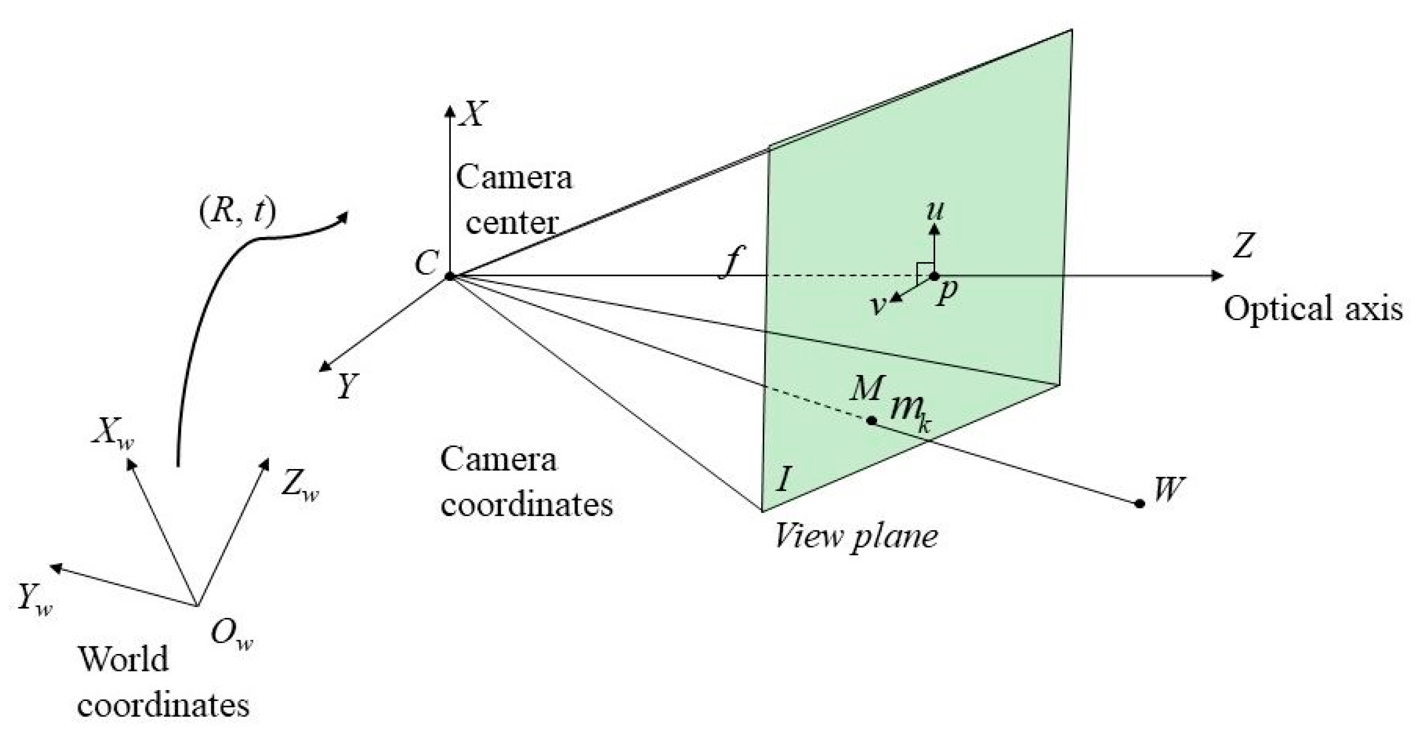
Figure 1. Pinhole camera geometry model. C is the camera center and p is a principal point in the view plane. f is the local length in millimeters.
Electronics 09 00906 g001
Figure 2. Profile of depth image-based rendering (DIBR) virtual view synthesis.
Electronics 09 00906 g002
Figure 3. Profile of traditional 3D warping d ( u , v ) denotes the depth value in the depth map corresponding to the coordinates ( u , v ) .
Electronics 09 00906 g003
Figure 4. Flowchart of the proposed system.
Electronics 09 00906 g004
Figure 5. Example of depth map preprocessing for Breakdancers. (a) Initial depth map and (b) processed result of (a).
Electronics 09 00906 g005
Figure 6. Example of traditional 3D warping. (a) Texture image, (b) depth map, (c) 3D warped texture image with erroneous points, corresponding to (a), and (d) 3D warped depth map with erroneous points, corresponding to (b).
Electronics 09 00906 g006
Figure 7. Profile of the improving 3D warping process in DIBR.
Electronics 09 00906 g007
Figure 8. Filtering results. (a) Filtering the entire depth map, (b) filtering the holes.
Electronics 09 00906 g008
Figure 9. Results of 3D inverse warping rendering (left view). (a) and (b) the virtual view and the corresponding depth map. (c) and (d) Results of 3D inverse warping rendering corresponding to (a) and (b), respectively.
Electronics 09 00906 g009aElectronics 09 00906 g009b
Figure 10. Virtual views with the same holes warped from the main and auxiliary views. (a) V m a i n and (b) V a u x .
Electronics 09 00906 g010
Figure 11. Example of brightness adjustment. (a) Nonadjusted and (b) adjusted.
Electronics 09 00906 g011
Figure 12. Profile of fast matching method (FMM) inpainting method [18]. (a) An example of region Ω and its boundary δ Ω for inpainting and (b) gradient value I ( q ) of q point corresponding to point p.
Electronics 09 00906 g012
Figure 13. Example of boundary region replacement for hole.
Electronics 09 00906 g013
Figure 14. Inpainting results. (a) View with holes, (b) boundary replacement, (c) inpainting result of (a), and (d) proposed inpainting result corresponding to (b).
Electronics 09 00906 g014
Figure 15. Cumulative execution times corresponding to the number of frames compared with our proposed method, and the methods of Chang et al. [21], Cho et al. [19], Luo and Zhu [26], and Oliveira et al. [27] (a) Ballet video and (b) Breakdancers video.
Electronics 09 00906 g015
Figure 16. Comparative results of peak signal-to-noise ratio (PSNR) value by frame. (a) Ballet dataset and (b) Breakdancers dataset.
Electronics 09 00906 g016
Figure 17. Comparative results of structural similarity (SSIM) value per frame. (a) Ballet dataset and (b) Breakdancers dataset.
Electronics 09 00906 g017
Figure 18. Synthesized virtual view for 1st, 36th, and 73rd frames on Ballet dataset. (a) Ground truth of Camera 4 of (b) Our proposed method. (c) Chang et al.’s method [21]. (d) Cho et al.’s method [19]. (e) Luo and Zhu’s method [26]. (f) Oliveira et al.’s method [27].
Electronics 09 00906 g018
Figure 19. Synthesized virtual view for 1st, 36th, and 73rd frames on Breakdancers dataset. (a) Ground truth of Camera 4 of (b) Our proposed method. (c) Chang et al.’s method [21]. (d) Cho et al.’s method [19]. (e) Luo and Zhu’s method [26]. (f) Oliveira et al.’s method [27].
Electronics 09 00906 g019
Figure 20. Enlarged images corresponding to the 1st and 73rd frames of Ballet and the 36th frame of Breakdancers. (a)Ground truth of Camera 4 of (b) our proposed method, (c) Cheng et al.’s method [21], (d) Cho et al.’s method [19], (e) Luo and Zhu’s method [26], and (f) Oliveira et al.’s method [27].
Electronics 09 00906 g020
Table 1. Average number of holes (pixel points) for one image compared with traditional 3D warping and improved 3D warping.
VideoTraditional 3D WarpingImproved 3D WarpingReduced Rate per Image (%)
Ballet126,605111,5011.9
Breakdancers74,10556,7622.2
Table 2. Execution time in seconds.
BalletBreakdancers
MethodAverageTotalAverageTotal
Our proposed0.6969.790.7676.01
Chang et al. [21]101000.3310.021002.96
Cho et al. [19]11.421142.8111.201120.82
Luo [26]73.547354.7566.506650.17
Oliveira et al. [27]9.4995,049.798.19819.27
Table 3. Comparative results.
BalletBreakdancers
MethodAve_PSNR (dB)Ave_SSIMAve_PSNR (dB)Ave_SSIM
Proposed33.100.92134.490.913
Chang et al. [21]29.970.92031.730.896
Cho et al. [19]25.200.93427.170.885
Luo [26]31.640.83130.80.817
Oliveira et al. [27]28.910.84629.240.843