1. Introduction
It has been compulsory for the patients or guardians to sign all of the paper consent forms in person but the hospitals are now ready to digitalize this process to avoid any possibility of misplacement or delivery delays to the operating room. In this aspect, this study introduces a digital signature authentication system that is exclusive to mobile health care service.
As such, there are many recent attempts to digitalize the patient consent form prior to surgery [
1]. At the same time, as the problems concerning the security of personal information when the patients are filling in the form have become an issue, other types of authentication systems using individual physical features are being developed [
1]. One of them is biometrics, which is a technology to identify a person by analyzing the different features of users have [
2,
3]. Biometrics technology includes signature, fingerprint, voice, iris, vein, and face recognitions. This study proposes a surgery consent signature authentication system for the mobile health care system that is based on a digital forensics methodology to improve the analysis method and security of signature recognition systems.
The electronic signature is a sort of a smart content that is processed with a simple interface, rather than the complex ones, and it can be defined as intelligently personalized content [
1,
2,
3]. The smart contents should be quickly provided for the customers who are in the process of purchase or a first time visitor [
4,
5].
The phrase “complex ones” mentioned here refers to all sorts of authentications, such as verifying oneself, validating the location information, address of a credit card user, and/or a Card Verification Code (CVC) number, similar to the ones that are being used for the current electronic payment systems. Signature is a traditional tool of confirming one’s own intention and the signatures written with an electronic pen are also currently being used to authenticate a person at the court. A variety of technologies are available for authenticating the signatures and especially for the electronic signatures, a special algorithm is being used along with the handwriting forms stored in the existing DataBase (DB).
Authentication methods that use individual characteristics are being developed due to the development of digital technologies and the emergence of security problems concerning personal information. One of them is biometric technology (biometrics), which distinguishes individuals by analyzing their different characteristics. Biometrics includes signature, fingerprint, voice, iris, face, and vein recognitions [
5,
6].
This paper is organized, as follows: Chapter 2 discusses some of the related research works followed by the discussion on the method of signature data extraction in Chapter 3. Subsequently, Chapter 4 deals with “Analysis of Signature Data”, whereas Chapter 5 reveals the prototype while discussing about system implementation and related considerations. Meanwhile, Chapter 6 explains the significance of the proposed system in comparison to the other research works along with interesting debates. Finally, Chapter 7 concludes the research.
2. Related Research
The management expense for various types of consent forms or other documents used at the hospitals have been increasing due to increased duty hours, use of huge quantity of papers and their storage in the process of form completion, processing or management. Additionally, there are issues involving personal information leaks, inefficiencies in the business process, and/or incurring of unnecessary costs. The hospital electronic consent solution proposed by FORSC [
4] can largely improve the business process by transforming various types of consent forms, such as medical checkup or surgery consent forms, etc., into an electronic document. With this solution, a patient can receive the explanations about checkup, procedure, or surgery plan for him/her to consent through the tablet PC carried by the medical staff. After the patient electronically signs the document, it will be stored in the hospital’s internal document server automatically. It is expected that the reliability and level of hospital service will be improved by creating such a medical environment.
Meanwhile, the hospital electronic consent system for a surgery or medical check offered by BIT Computer [
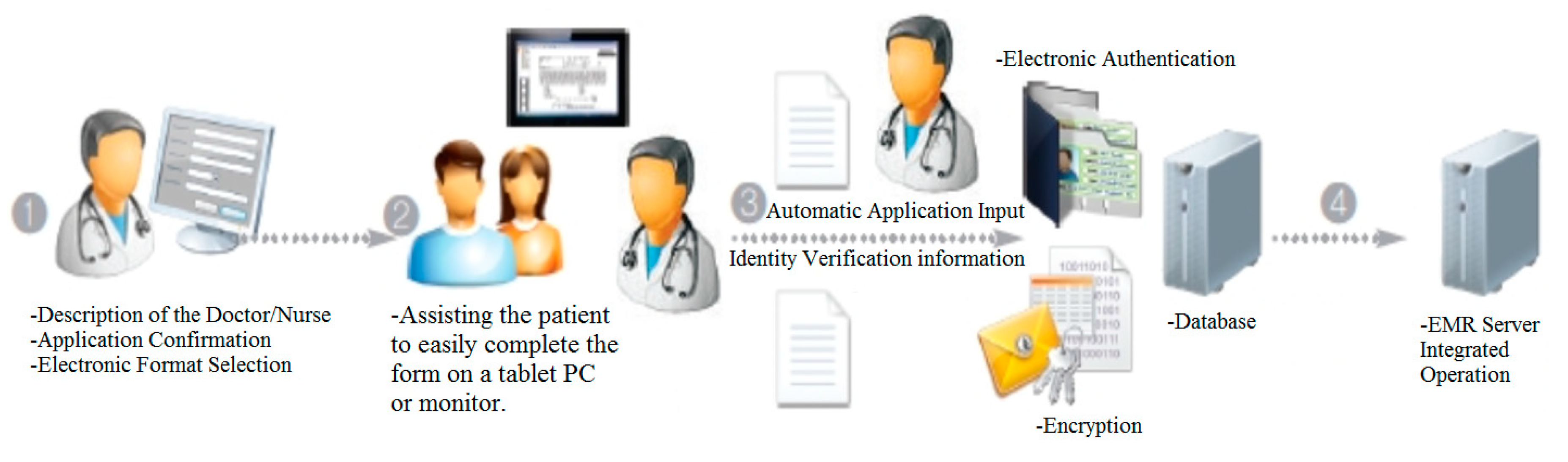
5] is a solution that allows a customer to complete the electronic consent form shared with the medical staff on a tablet PC or mobile device monitor by using an electronic pen. The form can be simultaneously implemented on either device’s monitor for signing so that both parties can reduce the time usually required for them to fill out the paper consent form significantly, increasing the customer convenience.
The major functions are as follows: first, assisting the patient to easily complete the form on a tablet PC or monitor as if he/she is writing on a paper; second, establishing a medical information system link. Third, achieving synchronization between the hospital ward and administration on a patient device screen to allow the person in charge to check the form filled in on the tablet PC monitor; and, the last, implementing an electronic authentication or encryption module of a template file.
Figure 1 shows the workflow of the electronic solution provided for medical checkups or surgeries.
Currently, various types of biometric techniques are being studied or applied and one of them is a technique that uses the iris or retina pattern, it has been known that they are different, even between twins, and do not change for a lifetime, unless a person gets seriously injured or be diseased in his/her eye. The retina recognition technique is one that uses the characteristic of a rear capillary vessel that it does not change during one’s entire life like a fingerprint [
6,
7,
8]. One of the merits of this technique is that it has more attributes that the fingerprint, but, as the user has to get very close to the retina scanner, it is not received well by the users. The iris recognition technique is one that authenticates the user based on a doughnut-shaped iris pattern located between the pupil and the white. The advantage of this technique is that the pattern can be captured with a camera from the distance of approximate one meter. It is possible to identify a person just by comparing 1/3 of the stored code information since every person has a different iris pattern. In this regard, the security of this technique stands out among the currently available biometric techniques. However, it is quite hard to miniaturize its equipment, so that its commercialization or generalization is also difficult. Another demerit is that the system can be much more expensive than the others.
The hand geometry recognition is the first automated technique among the biometric techniques, which is based on the observation that the lengths of fingers of the individual person are different. Currently, the analysis of digitized finger shapes involves not only their lengths, but also other various features. This technique facilitates real-time processing due to its simplicity and the requirement of lesser throughput but it also has a problem of low accuracy. This technique has been used to identify a suspect who has left no fingerprints, but only the palm print and its application to the other areas is still being researched [
9,
10].
The vein recognition is a security technology that is based on the fact that the vain pattern in the back of the hand or the wrist varies in each person as the fingerprints. One of its merits is that a relatively good image can be obtained, even from the simple injuries or the contaminations caused by the light-transmitting substances. Additionally, the security level of this technique is quite high, as veins are almost impossible to copy. However, an infrared light and an optical filter are often used to acquire a vascular image, but it is not easy to extract the area where the veins are being distributed from the back-hand skin, not to mention the complexity that is involved in organizing it the system hardware. Despite such difficulties, Lotte Data Communication Company has succeeded in applying this technique to a Seven Eleven convenient store as a test bed experiment. The face recognition can be regarded as the most natural biometric technique, as people mostly use the facial patterns to recognize the others. However, it is necessary that only the facial part should be separated for the recognition process but most of the time, people’s faces are not stationary so that the separation process can be quite difficult. For the recognition of a face, a feature-point-based method where a thermal image of facial vessels is captured with an infrared camera or the Principal Component Analysis (PCA)-based method that uses a 3D facial image is being currently used. The expected area where the face recognition technology will be used widely is the robotic technology-based agent service. The robots can identify the people with this technology and take appropriate actions, or provide a customized service of searching the scenes where a particular person appears in the news programs. This technique is being used by iPhone 10 and the People’s Republic of China’s Tenhwang project [
10].
The voice recognition is a technique that identifies a person or a linguistic meaning by comparing a speech with the voice data stored in the database after converting the voice characteristics, such as dynamics or tone of a sound. Currently, this technique is being used for the name or word-based automatic dialing service, voice-activation program for computer commands, basic note-taking, and internet access, as well as the voice-recognizing IBM OS/2 Warp. However, one’s voice could change later due to his/her health condition (e.g., heavy cold, laryngitis, etc.), or the surrounding noises may affect the system. Additionally, there would be a problem of intentional voice change or deliberate imitation of other’s voices, causing the recognition level to drop. Such problems are yet to be solved.
Since the start of human beings using the letters, the signature is a sort of agraphic-based biometric system that has long been used. People still write their names on documents, music scores, pictures, sculptures, or handicrafts. There are to major methods: the offline method where a signature is being optically captured by the scanner or the camera and then compared through the analysis and the online method, where the dynam characteristics of the signature, such as the movement, speed, and pressure, are analyzed while one is entering his/her signature on an electronic pad. Clearly, the most widely known disadvantage of this technology is that an expert forger can easily forge one’s signature. For this reason, when requiring a high-level security, it will be safer to use the other recognition technology (s) such as the ones that are mentioned above. Thus, a system where one’s signature information is first stored in the cloud database to compare with the currently signature is implemented with Java in this study.
In the majority of cases, the signature verifications that were performed during the last few decades were either an offline or an online approach and, recently, the automatic handwritten signature verification system that verifies the authenticity of signatures used for Australian passports was introduced to prevent identity fraud or theft. The fuzzy modeling method was used when developing this system to achieve a more accurate recognition [
11,
12]. At the same time, the hybrid handwritten signature verification system that compares signatures with the reference data was also developed. The signature data that were acquired by the digitizing tablet were then used for the segmentation process for the offline-scanned data (signature) for comparison [
13].
Meanwhile, another signature verification system that extracts a variety of the static signature features, such as height, slant, and others, along with dynamic features, including velocity, pen-tip pressure, and a few other necessary data to train network topologies has been introduced [
14]. In [
15], the signature verification system employing a hidden Markov model to represent and verify the signature data is described. The instrumented data gloves mounted with sensors to detect finger bend, hand position, and orientation are used for verification [
16].
In [
17], an automatic signature verification system that relies on the global features that summarize various aspects of the shape of a signature together with the dynamics of signature production is discussed. Meanwhile, the signature recognition algorithm that focuses on the pixel-to-pixel comparisons while using extensive statistical analysis, standard deviation, variance, and the theory of cross-correlation is outlined in [
18]. The verification system that recognizes signatures with online reference data acquired with a digitizing tablet and three other classification schemes is described in [
19].
The improved level of signature forgery verification systems is described in [
20], whereas the criterion of an improved signee registration using the entropy measure against online genuine signatures is presented in [
21]. The online dynamic signature verification system that employs a set of 49 normalized features that tolerates inconsistencies in a genuine signature and retains the power to distinguish forgeries is explained in [
22]. The statistical quantization mechanism that mitigates subtle intra-class variations in signature features to distinguish the differences between genuine and fake signatures is described in [
23].
The algorithm of the online signature verification system that employs the two-level verification approach that extracts the wavelet features and uses the neural network recognition has been proposed in [
24], whereas the dynamic signature verification system that uses the wavelet transformation for the back propagation neural network is described in [
25]. The other online signature verification systems that are based on the local information time functions are also described. The discrete one-dimensional (1D) wavelet transformation is performed with these properties in mind [
26]. The Discrete Wavelet Transform (DWT), which achieved a higher verification rate than the time-domain verification system in extracting distinctive features from the signatures, is reported in [
27,
28]. Using the DWT as a signature feature extraction tool has been studied in several previous studies [
24,
25,
26,
27,
28], where the DWT was performed for the genuine signatures but not for the skilled forgeries. Additionally, these studies did not offer any effective forgery detection solutions.
When the signature recognition technology is examined from the device perspective, there are methods of using touch screen or tablet PC, or by using the position information of the hand by attaching an inertial sensor to the wrist. The machine learning algorithm that is mainly used for sign recognition includes a Hidden Markov Model (HMM) [
29], which uses a chain code, and a Support Vector Machine (SVM) [
30], which classifies two classes and finds a classification boundary that maximizes margins. HMM is problematic, in that it cannot apply newly proposed features. Since SVM is basically a binary classifier, it is complicated to implement when it is expanded to a multi-class classifier. Instead of analyzing each signature one by one, this paper uses all of the algorithms to analyze the signature over several steps. In doing so, it was discovered that applying various algorithms can improve the accuracy more than analyzing the signature through only one algorithm and, moreover, that algorithms with good recognition rates may differ by the type of signature. Therefore, the cloud database is designed and implemented for the algorithm to be intelligently selected using an intelligent agent [
31] for efficient application.
Thus, in this paper, the methods, such as segmentation, spatial pyramid matching, and boundary matching, were used to analyze the signatures instead of using the famous signature analysis tool Dynamic Time Warping (DTW) algorithm. Additionally, instead of applying these algorithms to the targeted signature separately, all of them were used together in each different analysis stages.
The result showed that such a method had increased the accuracy but the individual recognition rates were different, depending on the forms of signatures. For this reason, the system was designed and implemented in a way that the cloud database will find a suitable algorithm and interact with it efficiently. That is, instead of proposing a new algorithm, this signature authentication system was implemented in a way that the digital signing process will interact with the algorithms associated with the signature recognition technology.
3. Signature Data Extraction
Among these methods, the focus was laid on the analysis method used for recognizing the signatures. Many research studies have been conducted for signature recognition technology in the past, but they are rarely being used at present, since they are vulnerable to forgeries. Thus, instead of a popular existing authentication method that uses a DTW method, an attempt was made to test a new signature recognition method by applying the segmental units comparison and Bag of Word methods, followed by its comparison with the DTW method.
The analysis of a signature is largely performed through three steps. First, calculate the average time that is required to write a signature based on its length by measuring the required time several times, and then compare it with a new value entered. Second, store the signature’s stroke ordering in the database to compare with a new value. Third, impose the signature over a grid and check how much the signature coordinates are contained in each section, regardless of the size of signature. Subsequently, by converting the results into percentages, compare them with the new values.
A database that manages the signature information will be constructed by developing a signature-input application in order to generate an ideal comparison value through sufficient learning time and then acquiring a sample signature for authentication purpose through three steps.
3.1. Development of Database and Application
The Android Studio-supported SQLite was used for the database that stores the data values of a baseline signature. Additionally, tables that use individual algorithms were separately created to receive coordinate values. The application that receives signatures and stores values was developed with Android Studio. This application stores the obtained coordinate values based on the signature-writing time with the timer once the signature has been entered using the touch function of a smart phone. Moreover, in addition to coordinates, the picture of the signature will be stored in the internal storage of the same smart phone to show detailed differences between the stored signatures. The differences can be checked with pictures; at the same time, the concordance rate (%) between the used algorithms will be represented with a pie graph.
3.2. Preprocessing
In order to use stored coordinates for the analyses, they must go through a preprocessing process that minimizes the variations in the signatures that are caused by slippery surface or the signer’s hand-shaking. This process includes a sampling process that improves the comparison processing speed when there are too many coordinates for the received signature by taking a single sample coordinate in a given number of coordinates. The normalization process is another process involved, which minimizes the changes in the signature’s shape size and inclination.
The number of coordinates should be arranged to be similar to that before so that the coordinate values are normalized against the time taken to write the signature. Furthermore, since each signature size may vary, an operation called generalization, which makes the sizes of signatures similar to each other, will be performed. In this process, the size of the signature is determined based on the largest and smallest values on the X-axis and Y-axis, and then the signature is delivered after its segmentation.
5. System Implementation and Considerations
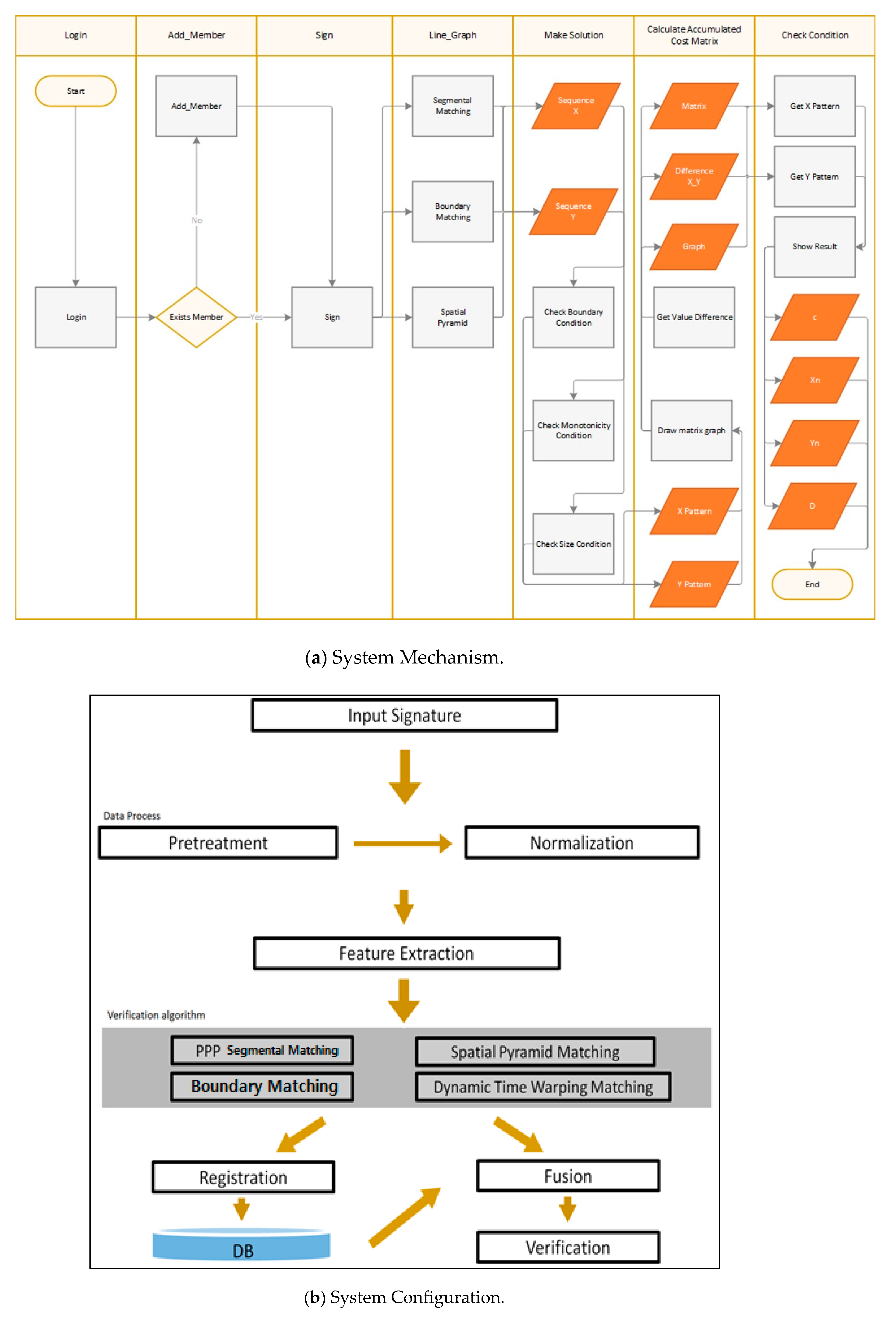
Figure 4 shows the overall system configuration, where the user signature will be entered first followed by its coordinates through a smart phone application. The coordinates of the received signatures are subjected to sampling based on the time spent writing the signatures and generalized by matching the sizes.
Next, the generalized coordinates are extracted to be transformed into forms that can be used for individual algorithms. The algorithms used for the implemented system include Partitioning Peak Points (PPP)/Segmental Matching, Boundary Matching, and DTW Matching Algorithms; others have been excluded, since they require complex arithmetic operations and do not serve the purpose of this paper. In each algorithm, the feature values between the signatures are calculated with the equation or method. The resulting values of the baseline signature will then be stored in the database to compare with other values for authentication.
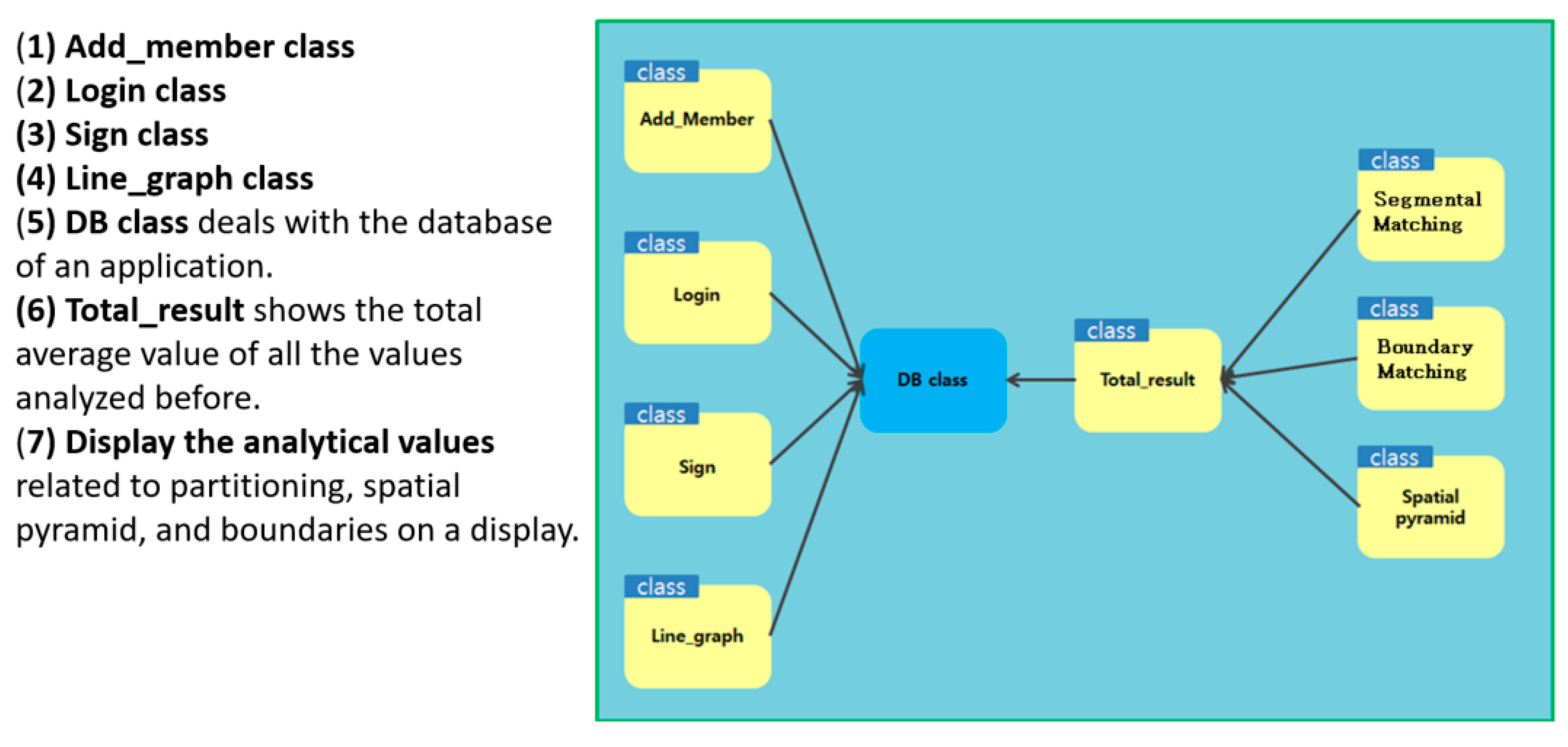
Figure 5 shows the entire Java Android Unified Modeling Language (UML). (1) Add_member class is a class that shows the operation of adding the user to the database; it refers to the class that deals with the SQLite managing the database. (2) Login class performs the process of proceeding to the next step when the user inputs the ID stored in the database. (3) Sign class literally shows the user’s signing process on a display, refers to the DataBase (DB) class, and delivers feature values to the database. (4) Line_graph class represents the database-stored values and analytical values with graphs following the standards. Histograms and pie graphs are common. (5) DB class deals with the database of an application. (6) Total_result shows the total average value of all the values analyzed before. (7) Display the analytical values related to partitioning, spatial pyramid, and boundaries on a display.
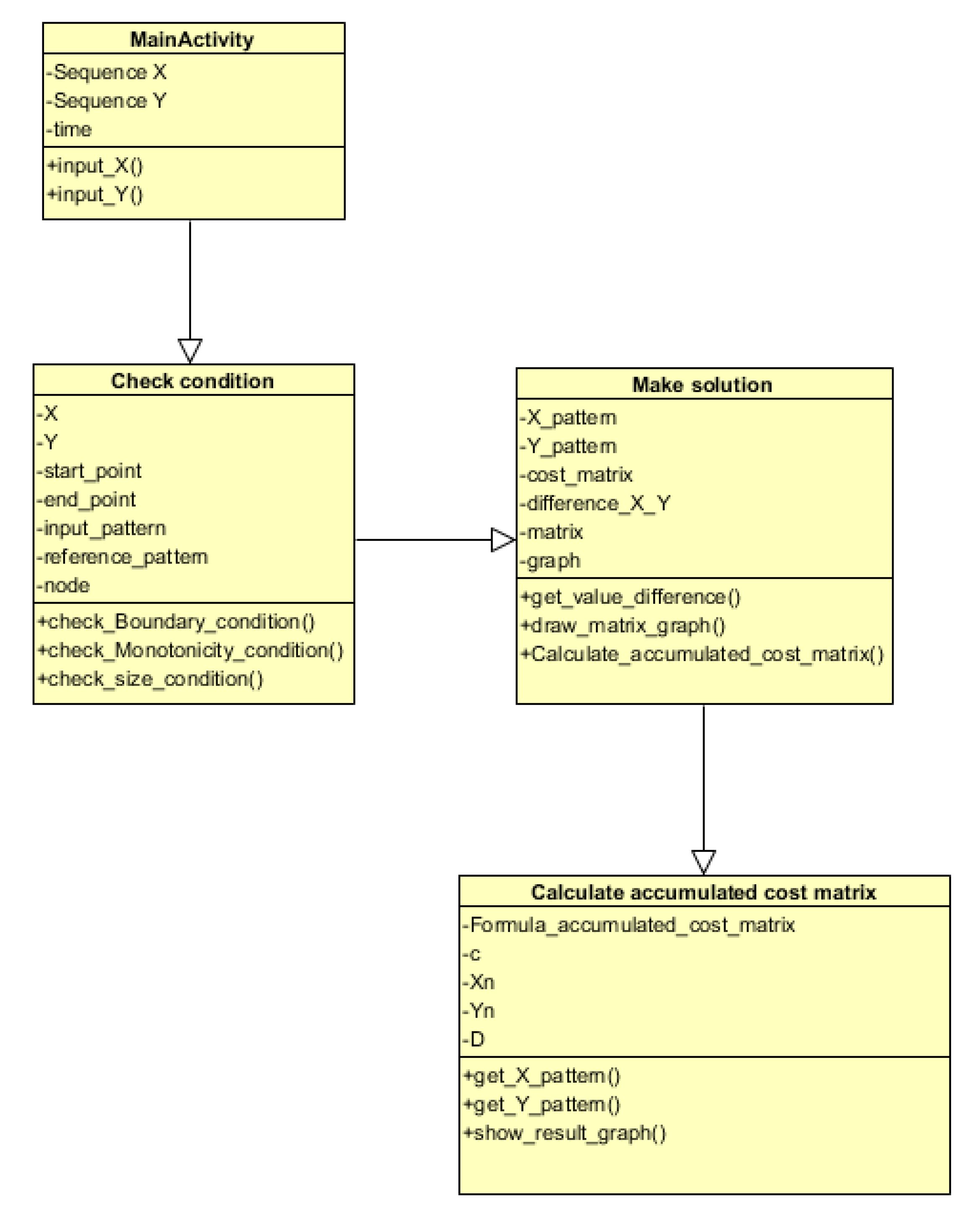
In this study, a Java-based UML was developed based on several algorithms for the proposed surgery agreement signature authentication system. The operating mechanism is initiated by entering a sequence set for both X and Y, respectively, along with a time variable in Main Activity. The information necessary for DTW should be entered first and at this time the DTW algorithm is required to satisfy the conditions of pattern matching, so that it is necessary to confirm that whether the three elements satisfy the conditions at the check condition class. The necessary terms should be entered as variable and the functions in the class include the Endpoint Limit Condition Test, Monotonic Increase Limit Condition Test, and Step Increase Condition Test. When the conditions have been met, the process moves on to the ‘make solution’ class. A function that calculates the distance of each x-y grid is included in this class, where another function that outputs the distance values with a matrix-form graph is also included. Finally, the process moves on to the class where an accumulated cost matrix is computed based on the cost matrixes. By calculating some lowest possible matrix by accumulating the values, the minimum distance between X and Y patterns can be found with the intelligent agent implemented in the previous study for authentication.
Figure 6 shows the UML of the surgery agreement signature authentication system.
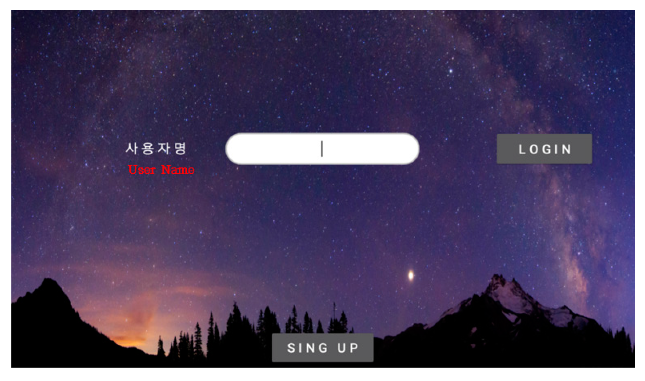
Figure 7 is a login screen that will store the baseline signature of the user under his/her ID to compare it with other signatures received in the future. During the registration process, the ID of the user and the analytical values of his/her signature will be stored in the application database. In addition, the picture of the baseline signature will be stored in the memory storage of the smart phone or tablet as an image file.
Figure 8 shows the signature to be entered for comparison. The analytical values are extracted in order to compare them with the DB-stored baseline signature. Similar to the baseline signature, this is stored in the database as an image file.
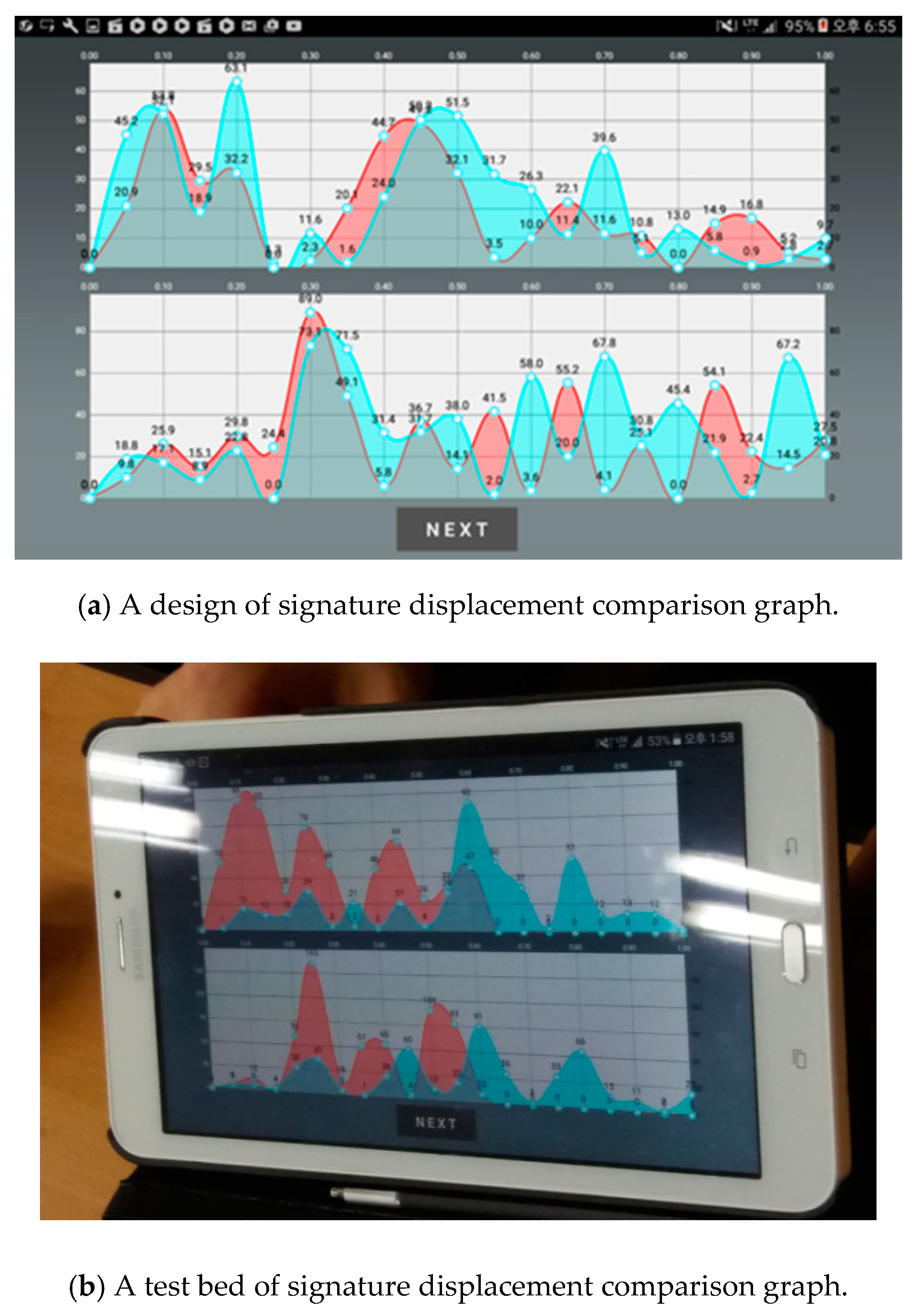
Figure 9 shows the displacements of both the baseline signature and the comparison signature over time with graphs. The graph above represents the X-displacements, whereas the graph below shows the Y-displacements. The light green areas indicate the DB-stored signature and the red parts represent the signature subject to comparisons.
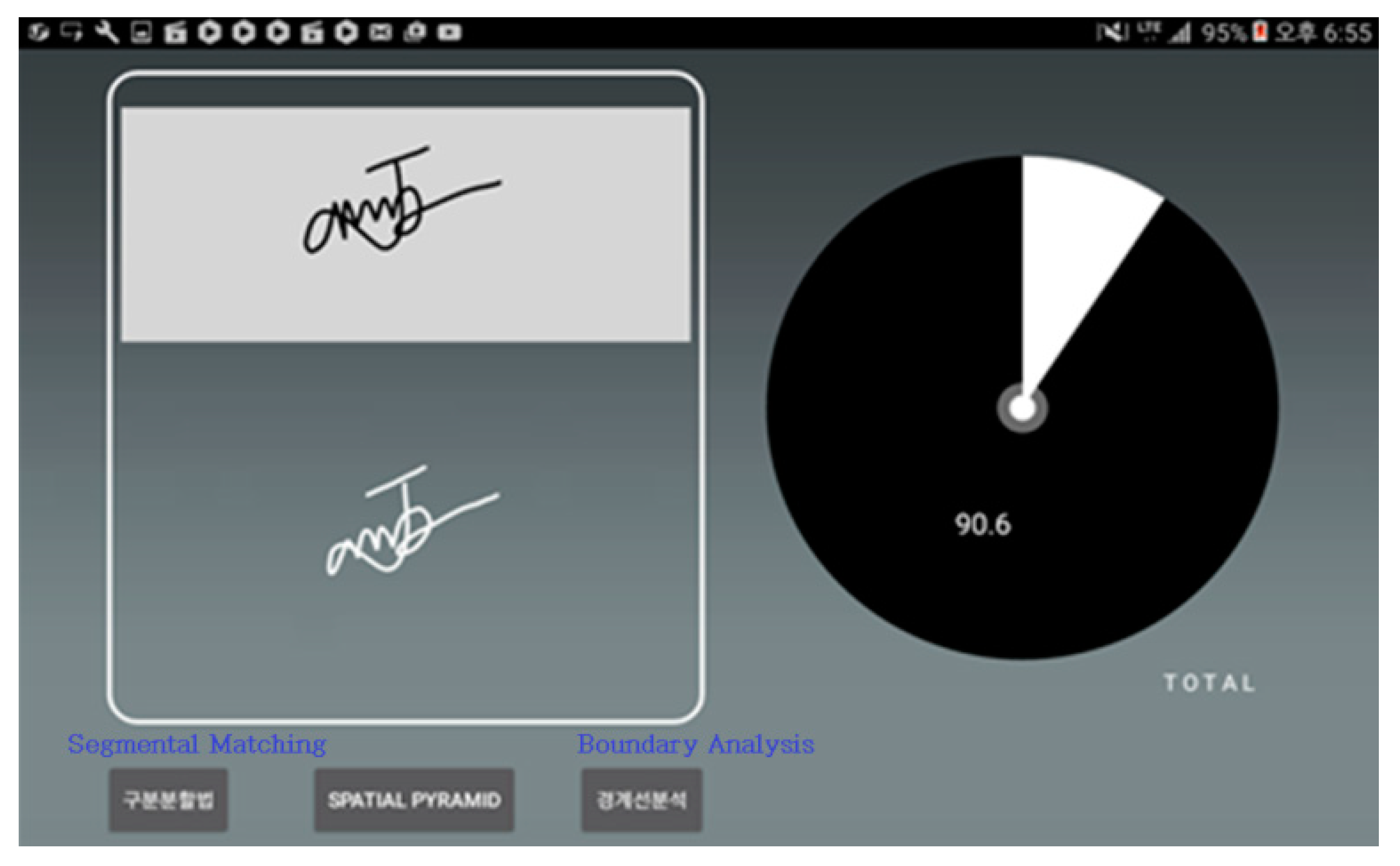
Figure 10 shows the image files of both signatures that are mentioned above and indicates the final comprehensive matching rate with a pie graph. The comprehensive matching rate was calculated by taking the averages in each algorithm. After setting the optimal probability boundary suitable for each algorithm, the system checks the analytical values as to whether they exceed the boundaries or if the average value exceeds the threshold. In either case, the signatures are deemed to be identical if the values exceed the boundary or threshold.
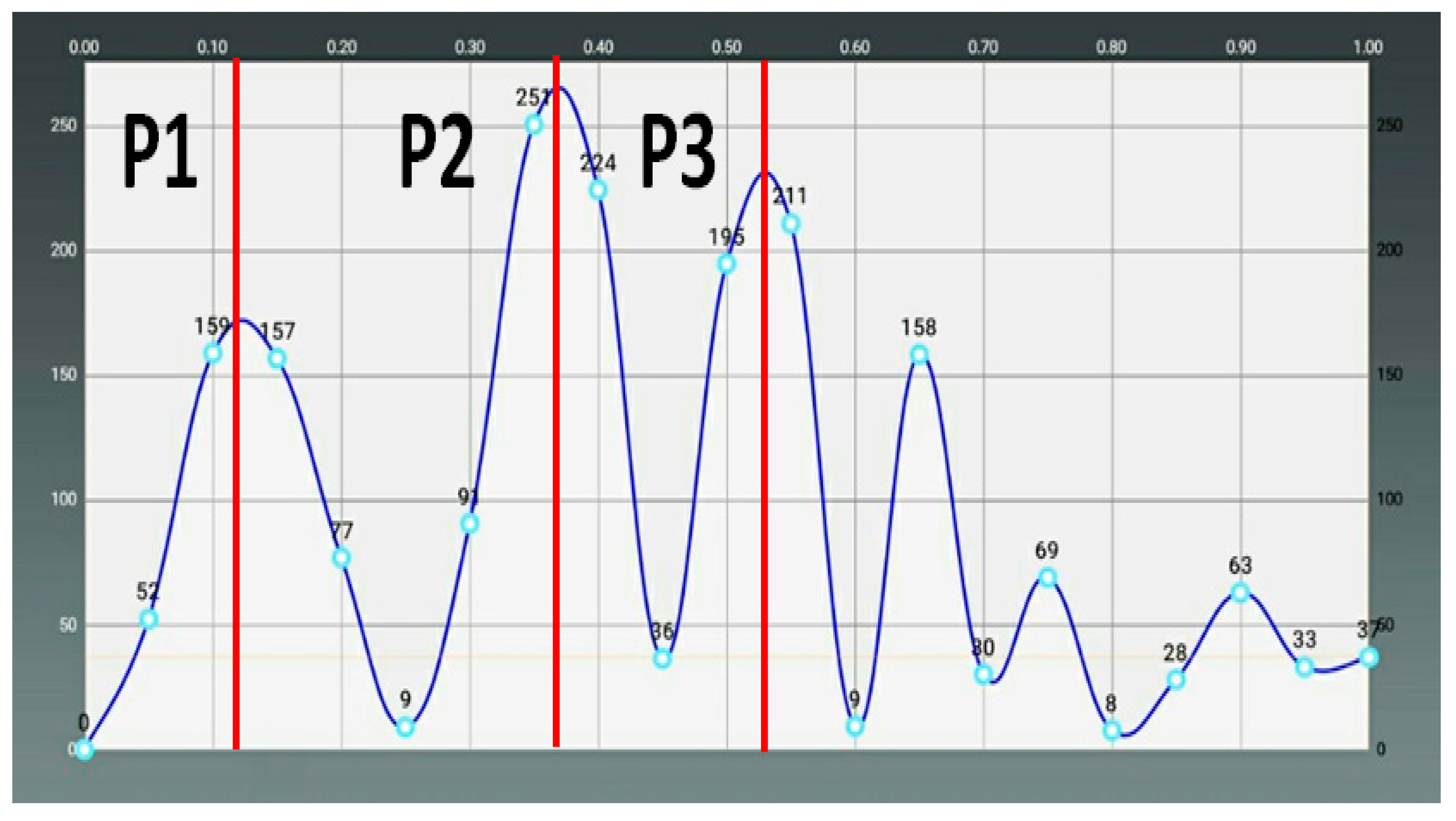
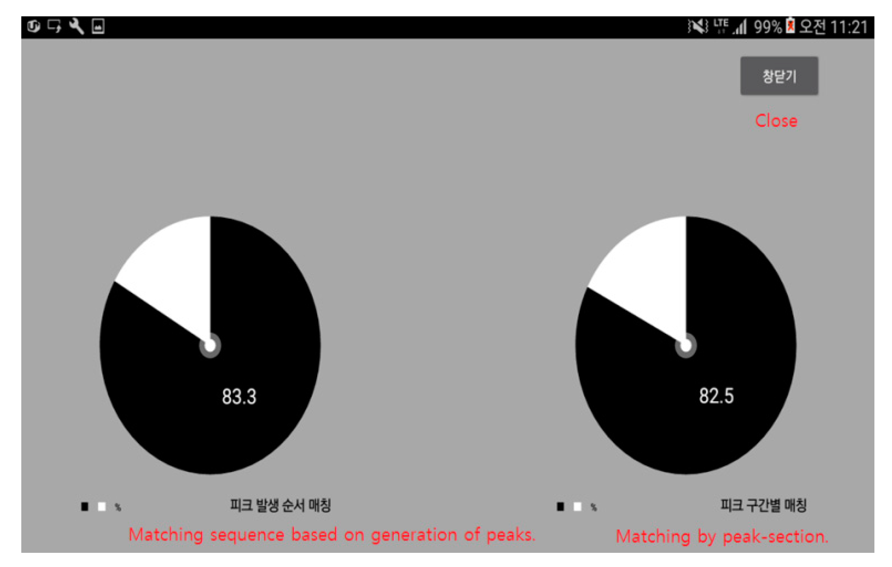
Figure 11 shows the matching rate calculated with the segmental matching method. The graph on the left shows the comparison result of the times when the peaks were generated, and the right graph indicates the matching rate based on the number of peaks in each section.
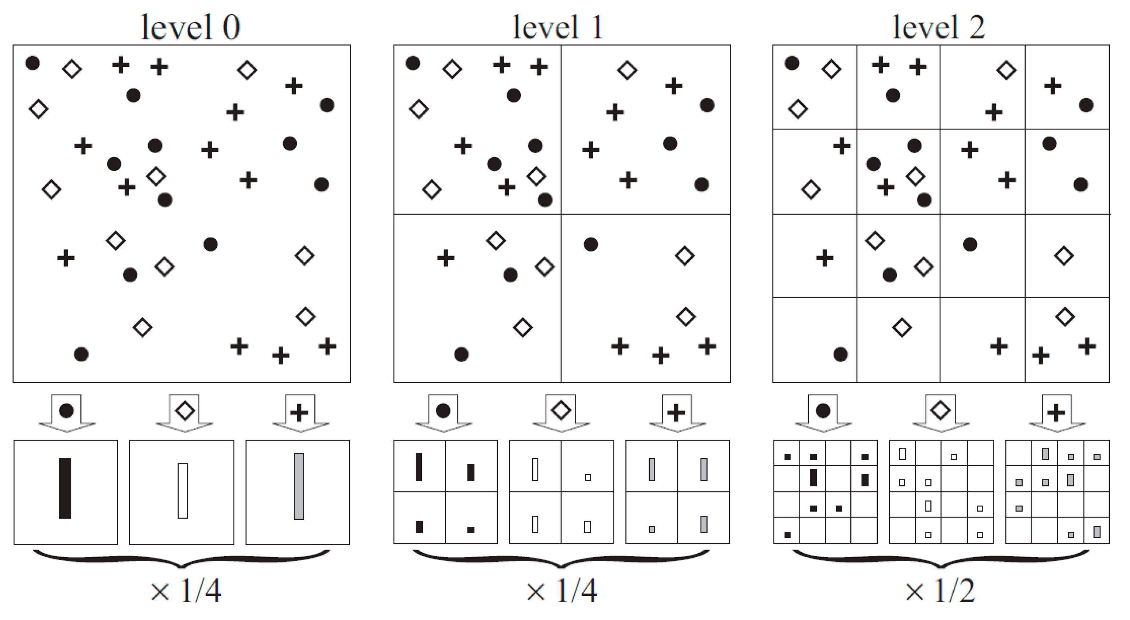
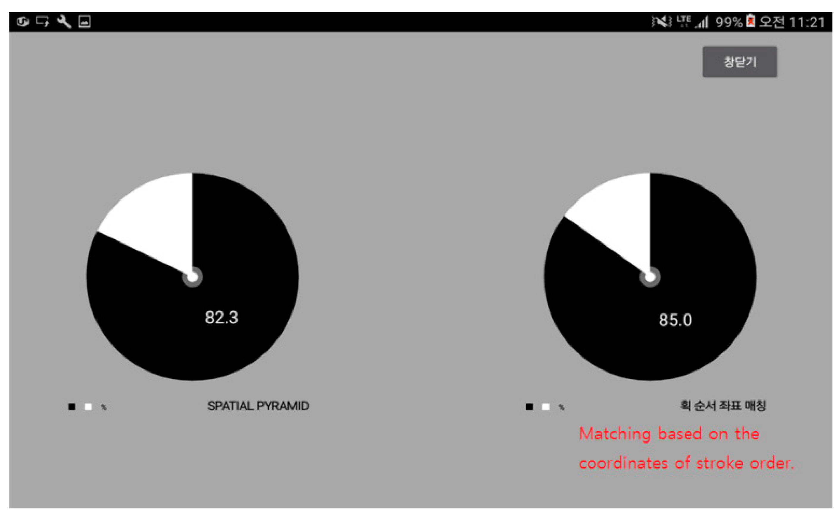
Figure 12 shows the matching rate after performing spatial pyramid matching. The graph on the left is the resulting rate after applying the spatial pyramid matching algorithm, and the one on the right shows the results that were obtained by comparing the spots where the strokes end.
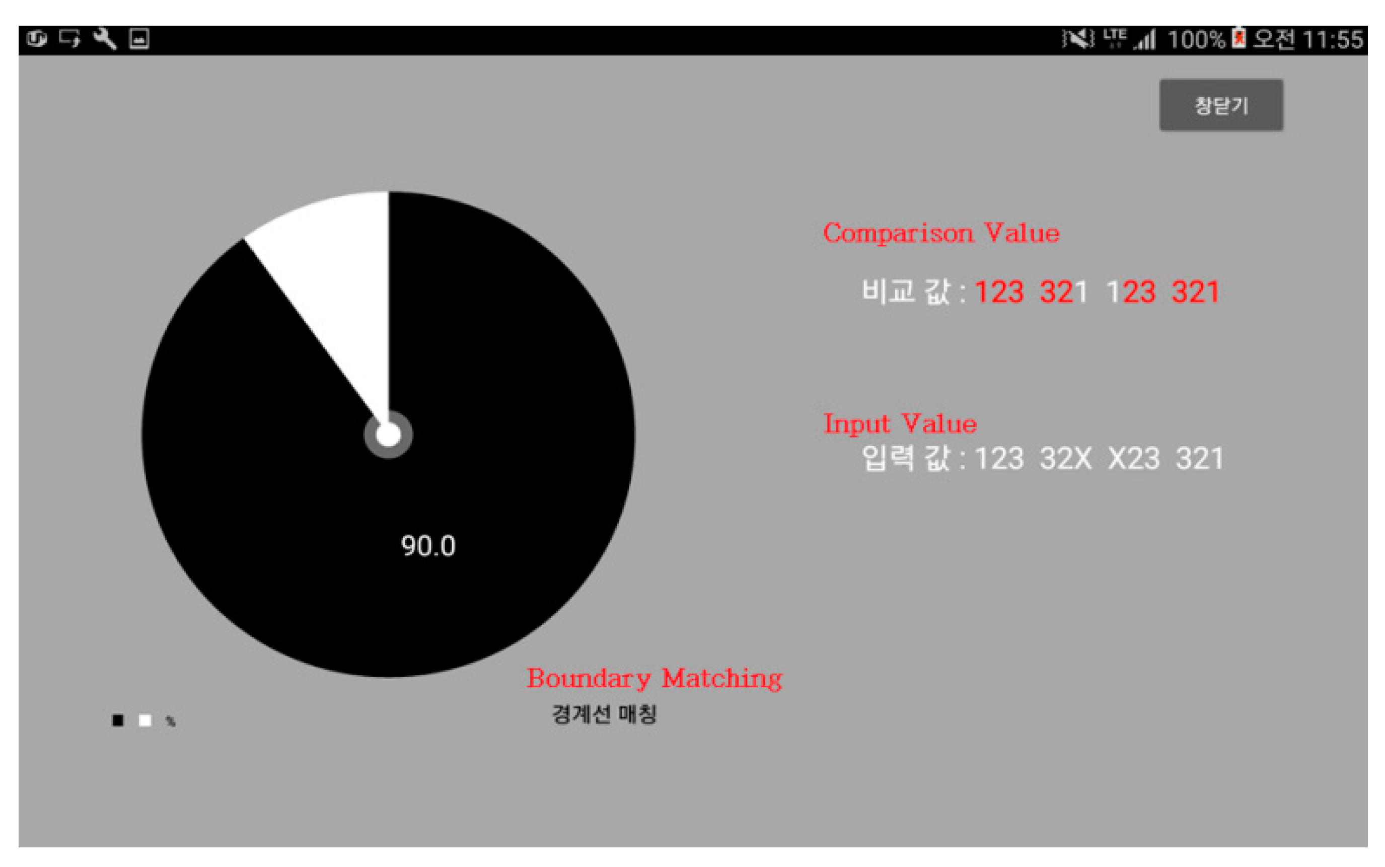
Finally,
Figure 13 shows the resulting matching rate after performing boundary matching. The left graph shows how much the analytical values contributed to the matching result, whereas the values in the upper right are the analytical values of boundaries that were stored in the Database (DB). The lower values are for the boundaries of input signature. Comparisons of these values have been performed for each section.
After receiving the same signatures five times from about 200 people (approx. 1000 signatures), the resulting values were confirmed to be different between the people while using their names as their signatures and the people who use their own (other than names) signatures. While the result of segmental matching showed similar higher matching rates for both groups, the result of spatial pyramid matching revealed that those who use their names exhibited higher precision. Contrary to this result, the same people showed lower precision when boundary matching was used. For the people who have their own special signatures, the precision level was higher when boundary matching was applied.
The proposed system includes such a function, so that the customer’s signature is compared with the card holder’s actual signature information registered in advance and the relevant parties, including the card holder himself/herself, will be notified of the analysis result. The details of this technology have been proposed to “H” hospital in Republic of Korea as a prototype.
7. Conclusions
Requiring the hospital patients or their legal guardians to sign a paper surgery or personal information collection consent form has been a common practice until recently. However, hospitals are trying to upgrade such a process through digitalization, due to the administrative inefficiencies involved (e.g., its loss or delayed delivery/notification). This study focuses on developing a digital signature authentication system for the use in the field of mobile heath care.
This research was used for implementing an improved DTW algorithm, where a basic DTW and the signing speed characteristic are used along with the distance measuring method that considers the angular variations. Additionally, instead of using each algorithm separately for signature analysis, all of the algorithms were used to perform analysis across several stages. An intelligent agent provides assistance during the analysis process. It was recognized that the accuracy of the analysis was much better when all the algorithm were used together. Additionally, the recognition rate of each algorithm was different, depending on the signature form. Thus, a system where the cloud database intelligently selects an algorithm with the help of an intelligent agent for the efficiency of the entire system has been designed and implemented.
The test bed experiment result showed that the system was flexible and efficient. Thus, in this paper, signatures were analyzed while using segmental, spatial pyramid, and boundary matching techniques instead of the existing popular DTW Algorithm. Likewise, instead of analyzing the signatures with the respective algorithm, all of the discussed algorithms were used in several stages. As a result, the precision level was higher than the one obtained from a single-algorithm analysis, which meant that the recognition rates would vary, depending on the form of the signature and the algorithm used.
The electronic consent form proposed in this paper can replace all of the paper documents (e.g., surgery consent forms, Agreement on Offering Personal Information, etc.) used at the hospitals and be checked and signed on a smart phone or tablet PC. It is similar to actual paper forms, as the signature can be entered, even if it extends beyond the boundary of the input window. The consent form is then sent to the operating room as soon as it is completed, so that both the patient and hospital do not have to worry about losing it or scanning it separately. The mobility-impaired patients can receive explanations just by watching them on a tablet PC and fill out the consent form on the spot. All of the data collected will be managed safely by the hospital information system. This paper conducted a signature analysis using segment division matching, spatial pyramid matching and boundary matching instead of the DTW algorithm, which is a widely known signature analysis method. Instead of analyzing signatures by using each algorithm one by one, this study uses multiple algorithms and analyzes the signatures in various steps. Through this, it was found that the application of various algorithms could enhance accuracy more than a signature analysis that uses only one algorithm. Additionally, the results showed that algorithms with good signature recognition may vary by the type of signature. Accordingly, cloud databases should be designed and implemented, so that algorithms intelligently select for efficient application.
One of the major demerits of this study was that the signatures were received by only using smart phones or Tablet PC (Personal Computer), and the analyses were based on their moving routes and speeds. More precise analyses could have been performed with more information obtainable through Electronic Pen Mouse or Exclusive Touch Pad. The author expects this technology to contribute to the field of biometric identification. The limit of this study is that the signature verification performance of the proposed system deteriorates when the signature is not entered by the actual cardholder, or when it is used at restaurants or pubs serving alcoholic beverages. This problem will be dealt with in the authors’ future work. Additionally, in the future work, this system will be proposed to the Korean credit card companies or for the smart banking systems to strengthen the security during the transmission process to achieve the similar level of security as encryption.


