Article

In-Band Full-Duplex Relaying for SWIPT-Enabled Cognitive Radio Networks

1
School of Electronic Engineering & Department of ICMC Convergence Technology, Soongsil University, Seoul 06978, Korea
2
Institute of Research and Development, Duy Tan University, Da Nang 550000, Vietnam
*
Author to whom correspondence should be addressed.
Electronics 2020, 9(5), 835; https://doi.org/10.3390/electronics9050835
Submission received: 30 April 2020 / Revised: 13 May 2020 / Accepted: 15 May 2020 / Published: 20 May 2020
(This article belongs to the Special Issue Wireless Power/Data Transfer, Energy Harvesting System Design)

Abstract

:
This paper studies sum rate maximization of a cognitive radio network, where a full-duplex relay (FDR) is considered to assist data transmission. An FDR equipped with multiple transmit/receive antennas is introduced to harvest energy from the radio frequency signal of the primary system to reuse the energy for its own data transmission. By exploiting the time-switching relaying protocol, we first formulate an optimization problem for the sum rate of primary and secondary receivers and then propose a low-complexity algorithm to find the optimal solution. Numerical results verify the effectiveness of the proposed technique for wireless information and power transfer in cognitive radio systems.

1. Introduction

In-band full-duplex (FD) radio has recently attracted much attention to improve the capacity of wireless communication systems. Theoretically, the use of FD radio is expected to double the spectral efficiency (SE) of a wireless channel [1]. However, the main challenge of an FD-based system is the self-interference (SI) due to the data transmission and reception operating at the same time and frequency. Accordingly, there have been many efforts to suppress SI, and thus, a small residual SI is usually taken into account [2,3,4,5,6]. Based on FD communications, relay-assisted networks have been studied in many works where the FD technique is used for relay nodes to forward the messages efficiently from the source to the destination nodes [7,8].
Another paradigm for radio resource sharing, known as cognitive radio (CR), allows an unlicensed secondary user (SU) to utilize the same spectrum that is allocated to a licensed primary user (PU), so that SE can be significantly enhanced [9,10,11]. To reap the benefits of both FD and CR, the authors in [12] proposed a new model, where an FD-enabled secondary transmitter (ST) is used to relay the messages from the primary transmitter (PT) to PU. The authors in [13] considered an FD relay (FDR) based on non-orthogonal multiple access (NOMA) to maximize the near user rate, while FDR selection applicable for multiple pairs of SUs and PUs was presented in [14].
Simultaneous wireless information and power transfer (SWIPT) has been accepted as a green solution for next-generation communication systems [15,16,17,18,19,20,21], in which the energy harvesting (EH) process enables the devices to recharge their own batteries through radio frequency (RF) signals. Consequently, SWIPT not only helps reduce the wasted energy, but also supports wireless networks with many devices, such as the Internet of Things (IoT) and sensor networks. There are four main types of SWIPT architectures: separate receiver, power splitting, time switching, and antenna switching. Among them, the time switching approach facilitates joint optimization in the signal processing under various conditions, i.e., interference management and quality-of-service (QoS) constraints.
In the context of SWIPT-integrated networks, there are many efforts to improve the system performance by applying SWIPT to both FD- and CR-based networks (CRNs). In [22], an FD-enabled system using SWIPT was proposed to improve spectral and energy efficiencies. In CRNs, the performance analysis for EH and system throughput was investigated in [23], indicating the effectiveness of SWIPT. To further enhance the performance for SWIPT-based CRN systems, the authors in [24] developed a model, where an FD-enabled access point simultaneously charges the battery of ST and receives the signals from PT in the first phase, and in the second phase, the ST transmits/forwards the messages to secondary/primary receivers (SR/PR). Although the CRN scheme in [23] could reuse the energy by sensing the appearance of the PT’s signal, the conventional EH based on single-input single-output (SISO) cannot exploit the benefit of the multiple-antenna technique. In addition, the use of an energy beam in [22,24] might lead to inefficient power consumption at the energy beaming sources, i.e., base stations and APs, due to the strong attenuation caused by the path loss. The above discussions motivate us to develop an FD-based CRN that takes advantage of the beamforming technique for SWIPT.
This paper investigates a CRN where the data transmission between an ST and an SR is entirely performed via an FDR. Differently from previous works, the data transmission operates in two phases of a time block as in the time-switching relaying (TSR) protocol, where the fraction is optimized so that the sum rate of the primary and secondary systems is maximized. In the first phase, the ST and FDR harvest energy from the primary signal and utilize the harvested energy to transmit their independent signals. With the given spectrum access and harvested energy, in the second phase, the FDR is enabled to assist PT and ST in forwarding the data to PR and SR, respectively. To the best of our knowledge, a thorough performance evaluation of FDR enabled by EH in CRNs has not been reported in the literature. The proposed model brings some advantages: (i) inherited from the property of relaying, the FDR utilizes distances geometrically near receivers for improving the system performance; (ii) FDR is able to exploit the benefit of the multiple-antenna technique to harvest energy and transmit data efficiently; (iii) the proposed model is particularly suitable for CRNs, in that the CRNs can sense the appearances of PT’s signals in one block transmission to recycle the energy from PT’s signal, instead of requesting the new energy beam from PT.
Under the proposed model, we formulate a novel sum rate maximization problem for both SR and PR, which is found to be non-convex programming. To solve the problem efficiently, we then propose a low-complexity iterative algorithm based on the inner convex approximation (ICA) framework. Numerical results are provided not only to demonstrate the effectiveness of the proposed system model and optimization algorithm, but also to show the performance trade-off between the secondary and primary systems under the multiple-antenna technique and fractional time optimization.
Notation: X H and tr ( X ) are the Hermitian transpose and trace of a matrix X , respectively. · and | · | denote the Euclidean norm of a vector and the absolute value of a complex scalar, respectively. x CN ( a , σ 2 ) indicates that the random variable x follows the complex normal distribution with mean a and variance σ 2 .

2. System Model and Problem Formulation

As illustrated in Figure 1, we consider a CRN consisting of a primary system with one PT and one PR and a secondary system with one ST and one SR. A decode-and-forward (DF)-based FDR equipped with N-receive and M-transmit antennas is primarily employed in the secondary system, under the assumption that there is no direct link from ST to SR due to path loss and shadowing. We denote the channel vectors from PT/ST to FDR by h z C N × 1 , z { p , s } , while g z C 1 × M represents the channel vectors from FDR to PR/SR. f p s C and f p p C stand for the channel responses from PT to ST and to PR, respectively. FDR is assumed to be a multiple-input and multiple-output (MIMO) device while PT and ST are merely equipped with one antenna (without loss of generality, the proposed system model can be extended to MIMO scenarios for PT and/or ST to further improve the system performance). Hence, H R R C N × M designates the self-interference (SI) channel from the transmit antennas to the receive antennas at FDR. In particular, the residual SI can be modeled as H R R = ρ H 0 , where the entries of H 0 follow a Rician distribution, and  0 ρ 1 denotes the level of SI suppression after applying cancellation techniques as proposed in [25].
Remark 1.
In this paper, we focus on the effect of the TSR protocol under the perfectly known channel state information (CSI). Therefore, the results of this paper will provide an upper bound of system performance. However, the following proposed model and method can be applied to a robust design under channel uncertainty by decomposing the perfect channels into the channel estimates and estimation errors [6].

2.1. Information and Power Transfer Model

To be energy-efficient, the data transmission of CRN is considered in a time block when the link between PT and PR sharing the same spectrum is sensed to be active. Accordingly, ST and FDR are allowed to harvest energy from RF signals transmitted by PT, and then, they use the harvested energy for their own data transmission. We consider a TSR protocol for joint energy harvesting and information processing [22], as illustrated in Figure 2. According to the TSR protocol, ST and FDR harvest energy from the PT’s signal for a fraction α ( 0 α 1 ) of a certain time slot k of duration T. The remaining ( 1 α ) fraction of the time slot is used for information transmission. As a result, the amount of energy harvested at ST and FDR can be respectively expressed as:
E s = η P p f p s 2 α T and E r = η P p h p 2 α T ,
where 0 < η < 1 denotes the energy conversion efficiency and  P p is the transmit power of PT. Correspondingly, the maximum available power at ST and that at FDR for the time duration ( 1 α ) T are respectively calculated as:
P s = α 1 α η P p f p s 2 and P r = α 1 α η P p h p 2 .
Herein, we suppose that the energies harvested by ST and FDR in the first phase time of α T are completely used for information transmission in the second phase time of ( 1 α ) T . The received signals at FDR, SR, and PR during the time duration ( 1 α ) T at the k th time slot are respectively given as:
y r [ k ] = H x [ k ] + P r ρ H 0 W s [ k ] + n r [ k ] ,
y s [ k ] = P r g s W s [ k ] + n s [ k ] ,
y p [ k ] = P r g p W s [ k ] + P p f p p x p [ k ] + n p [ k ] ,
where H h s h p and  x [ k ] P s x s [ k ] P p x p [ k ] H , with  x s [ k ] and x p [ k ] CN ( 0 , 1 ) being the transmit symbols of ST and PT in the k th time slot, respectively; the elements of n r [ k ] , n s [ k ] , and n p [ k ] CN ( 0 , σ 2 ) denote the additive white Gaussian noise (AWGN) at FDR, SR and PR, respectively. At FDR, a beamforming matrix W is applied to combat co-channel interference, yielding the transmit signal s [ k ] = x s [ k τ ] x p [ k τ ] H , where τ accounts for the time delay caused by the relay processing. The system is assumed to adopt a zero-forcing (ZF) detector A H and a ZF beamforming W at FDR:
A H H H H 1 H H , and W c G G H G 1 ,
where:
G H = g s H g p H H , and c = 1 tr G H G 1 .
Herein, the power control factor c is to ensure that the maximum transmit power at FDR does not exceed the harvested power in the corresponding transmission block. Furthermore, PT can transmit data directly to PR during the first phase, and thus, the received signal at PR via the direct link during the time α T is given as:
y p d i r [ k ] = P p f p p x p [ k ] + n p [ k ] .
It is assumed that the processing delay is negligibly small compared to the transmission time. Moreover, the time slot k is an arbitrary slot at which PT sends the signals to PR. For simplicity, we omit τ and k, hereafter.

2.2. Achievable Rates and Problem Formulation

The estimated data at FDR can be expressed as x ^ = A H y r . From (3) and (4), the signal- to-interference-plus-noise ratio (SINR) of the secondary system in each hop can be computed as:
γ ST , R = P s a s H h s 2 P p a s H h p 2 + P r ρ a s H H 0 W 2 + σ 2 a s 2 ,
γ R , SR = P r g s w s 2 P r g s w p 2 + σ 2 ,
where a s is the first column of A corresponding to h s ; w s and w p are the first and second columns of W corresponding to h s and h p , respectively. Similarly, the SINR of the primary system during the time ( 1 α ) T can be found as:
γ PT , R = P p a p H h p 2 P s a p H h s 2 + P r ρ a p H H 0 W 2 + σ 2 a p 2 ,
γ R , PR = P r g p w p 2 P r g p w s 2 + P p f p p 2 + σ 2 ,
where a p is the second column of A corresponding to h p . Furthermore, the SNR of the primary system for the direct link during the time α T in (6) is found as:
γ PT , PR = P p f p p 2 σ 2 .
The end-to-end (e2e) achievable rate of the secondary system can be expressed as:
R s = ( 1 α ) ln 1 + min γ ST , R , γ R , SR .
Similarly, the e2e achievable rate of the primary system that uses a maximal-ratio-combining (MRC) to combine (9) and (11) can be written as:
R p = R α + ( 1 α ) ln 1 + min γ PT , R , γ R , PR ,
where R α α ln 1 + γ PT , PR is a linear function with respect to α .
From (12) and (13), the optimization problem of maximizing the sum rate of the primary and secondary systems can be formulated as (To maximize the sum rate, we focus on the optimization of the time fraction α , which determines a trade-off between the energy harvesting and data transmission. The joint optimization of power allocation and time fraction will probably enhance the performance, but with much higher complexity.):
maximize α R s + R p ,
subject to 0 α 1 .
It can be seen that Problem (14) is non-convex, since the objective function in (14a) is non-concave. In what follows, a low-complexity approach to find the solution of (14) will be presented.

3. Proposed Solution for SRM Problem

We first transform Problem (14) into a tractable non-convex form and then apply the ICA method to devise a low-complexity algorithm.

3.1. Tractable Formulation for SRM Problem

We first introduce a new variable β with an additional constraint: α + β 1 . Accordingly, ( 1 α ) in (12) and (13) can be equivalently replaced by β . This provides a smoothing optimization instead of a strictly-splitting time slot in the TSR protocol. Then, we tackle the non-smooth functions in (12) and (13) by adding the following constraints:
γ ST , R 1 t s and γ R , SR 1 t s ,
γ PT , R 1 t p and γ R , PR 1 t p .
Therefore, R s and R p are respectively expressed as:
R s β ln ( 1 + 1 t s ) : = R ¯ s ,
R p R α + β ln ( 1 + 1 t p ) : = R ¯ p .
By using (16), we can equivalently rewrite (14) as:
maximize α , β , t R ¯ s + R ¯ p ,
subject to 0 α 1 , 0 β 1 ,
α + β 1 ,
( 15 ) ,
where t t s ; t p . We note that Problem (17) is still non-convex due to the non-concave objective in (17a) and the non-convex constraints in (17d).

3.2. Proposed Iterative Algorithm

In this subsection, we focus on convexifying Problem (17) by applying the ICA method to (17a) and (17d). To do this, we first introduce two approximate functions as follows.
  • Consider the function f ( x , y ) 1 y ln ( 1 + 1 x ) , ( x , y ) R + + 2 . It can be seen that f ( x , y ) is convex, since its Hessian is a positive definite matrix. According to [6], we can obtain an upper bound of f ( x , y ) around the point ( x ( κ ) , y ( κ ) ) as:
    f ( x , y ) A ( x ( κ ) , y ( κ ) ) + B ( x ( κ ) , y ( κ ) ) x + C ( x ( κ ) , y ( κ ) ) y : = f ˜ ( κ ) ( x , y ) ,
    where:
    A ( x ( κ ) , y ( κ ) ) 2 y ( κ ) ln 1 + 1 x ( κ ) + 1 x ( κ ) + 1 y ( κ ) , B ( x ( κ ) , y ( κ ) ) 1 x ( κ ) x ( κ ) + 1 y ( κ ) , C ( x ( κ ) , y ( κ ) ) 1 ( y ( κ ) ) 2 ln 1 + 1 x ( κ ) .
  • Similarly, an upper bound of a convex function g ( x , y ) x 2 y , ( x , y ) R + + 2 around the point ( x ( κ ) , y ( κ ) ) can be found as:
    g ( x , y ) 2 x ( κ ) y ( κ ) x ( x ( κ ) ) 2 ( y ( κ ) ) 2 y : = g ˜ ( κ ) ( x , y ) .
Inner approximation of (17a): We introduce a new variable δ that satisfies the following convex constraint:
1 δ β , δ 1 .
By substituting (20) into (16) and applying (18), the concave minorants of R ¯ s and R ¯ p at the iteration κ + 1 are respectively given as:
R ¯ s f ( t s , δ ) f ˜ ( κ ) ( t s , δ ) : = R ¨ s ,
R ¯ p R α + f ( t p , δ ) R α + f ˜ ( κ ) ( t p , δ ) : = R ¨ p .
It is observed that (17a) can be iteratively replaced by R ¨ s + R ¨ p , which is a concave objective function. We notice that when κ , the inequalities in (16), (20), and (21) hold with equalities.
To convexify (15), the following theorem is derived using the ICA framework.
Theorem 1.
For two arbitrary vectors x and y , let λ ( x , y ) η P p x 2 y 2 . The constraints in (15a) are convexified as:
α λ ( h p , ρ a s H H 0 W ) + β ψ ST , R ν ST , R ,
g ( κ ) ( α , ν ST , R ) λ ( f p s , a s H h s ) 1 t s ,
α λ ( h p , g s w p ) + β σ 2 ν R , SR ,
g ( κ ) ( α , ν R , SR ) λ ( h p , g s w s ) 1 t s ,
where ν ST , R and ν R , SR are newly introduced variables and  ψ ST , R P p a s H h p 2 + a s 2 σ 2 . Similarly, the constraints in (15b) are approximated by the following convex constraints:
α ϕ PT , R + β a p 2 σ 2 ν PT , R ,
P p a p H h p 2 g ( κ ) ( β , ν PT , R ) 1 t p ,
α λ ( h p , g p w s ) + β ( P p f p p 2 + σ 2 ) ν R , PR ,
g ( κ ) ( α , ν R , PR ) λ ( h p , g p w p ) 1 t p ,
where ν PT , R and ν R , PR are new variables and ϕ PT , R λ ( f p s , a p H h s ) + λ ( h p , ρ a p H H 0 W ) .
Proof. 
Please see Appendix A. □
For convenience, we define ν ν ST , R ; ν R , SR ; ν PT , R ; ν R , PR . By using (20), (21), and Theorem 1, the successive convex program providing a minorant maximization for (14) at the iteration κ + 1 is given by:
maximize S R ¨ Σ ( κ + 1 ) R ¨ s + R ¨ p ,
subject to ( 17 b ) , ( 17 c ) , ( 20 ) , ( 22 ) , ( 23 ) ,
where S { α , β , δ , t , ν } and, correspondingly, S ( κ ) = { α ( κ ) , β ( κ ) , δ ( κ ) , t ( κ ) , ν ( κ ) } at iteration κ . We successively solve (24) and update the involved optimization variables after each iteration until convergence, which is guaranteed to achieve at least a locally optimal solution of (14). In summary, the proposed algorithm for solving (14) is given in Algorithm 1.
Algorithm 1 Proposed iterative algorithm for solving Problem (14).
1: 
Initialization: Set κ : = 0 , ε : = 10 3 , R ¨ Σ ( 0 ) : = , and randomly generate an initial point S ( 0 ) .
2: 
repeat
3: 
 Solve (24) to obtain the objective value R ¨ Σ ( κ + 1 ) and solution S ( ) .
4: 
 Update S ( κ + 1 ) : = S ( ) .
5: 
 Set κ : = κ + 1 .
6: 
until R ¨ Σ ( κ ) R ¨ Σ ( κ 1 ) < ε .
7: 
Output: The solution α * = α ( κ ) . The corresponding achievable rate is given by (14a).
Complexity analysis: The proposed algorithm takes low complexity in the scene that all the constraints in (24) are conic constraints. In particular, the per-iteration complexity of solving (24) is O ( C 2.5 V 2 + C 3.5 ) , where C denotes the number of constraints in (24b) and V is the number of decision variables determined by the number of elements in S .
Remark 2.
It can be foreseen that the proposed algorithm is easily applied to an SR’s rate (resp., PR’s rate) maximization problem under the quality-of-service (QoS) constraint for PR (resp., SR) receiver, i.e.,
maximize S R ˜ Σ ( κ + 1 ) R ¨ s ,
subject to ( 17 b ) , ( 17 c ) , ( 20 ) , ( 22 ) , ( 23 ) ,
R ¨ p R ¯ p ,
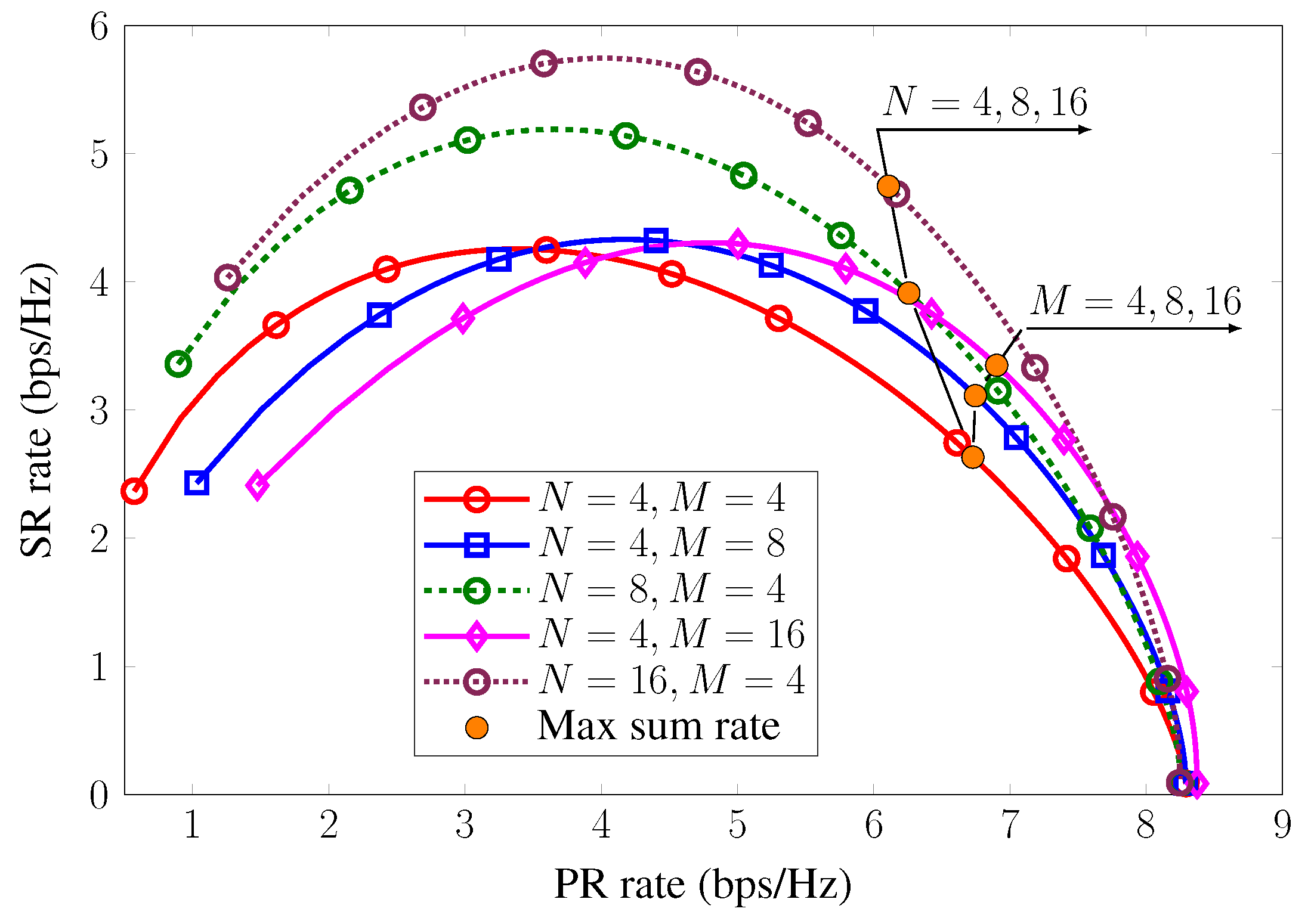
where R ¯ p is a data rate requirement for PR. In fact, Constraint (25c) is linear due to the property of the ICA method, leading to a convex programming in (25). Typically, this problem is associated with a trade-off between SR and PR rates, which is examined in Figure 5.

4. Numerical Results

We consider that an FDR (denoted by R ) equipped with N receive antennas and M transmit antennas is located 20 m away from PT, i.e., d PT , R = 20 m, where d x , y is the distance from x to y . An ST is located between PT and FDR such that d PT , ST = 2 m. PR and SR are located at two points, which are symmetric with respect to the line from PT to FDR, such that d R , PR = d R , SR = 5 m, d PT , PR = d PT , R 2 + d R , PR 2 m, and d ST , SR = d ST , R 2 + d R , SR 2 m. The channel responses are determined by h ¨ = d z φ h ^ , where h ¨ { h p , h s , g p , g s , f p s , f p p } corresponds to the link z { ( PT , R ) , ( ST , R ) , ( R , PR ) , ( R , SR ) , ( PT , ST ) , ( PT , PR ) } , respectively; the path-loss exponent is assumed to be φ = 3 , while the elements of h ^ follow CN ( 0 , 1 ) . Unless otherwise specified, the transmit power at PT, background noise power, and energy conversion parameter are respectively set as P p = 26 dBm, σ 2 = 104 dBm, and η = 0.5 [26,27,28], while the suppression level of the residual SI is set as ρ = 90 dB following the worst-case design in [29].
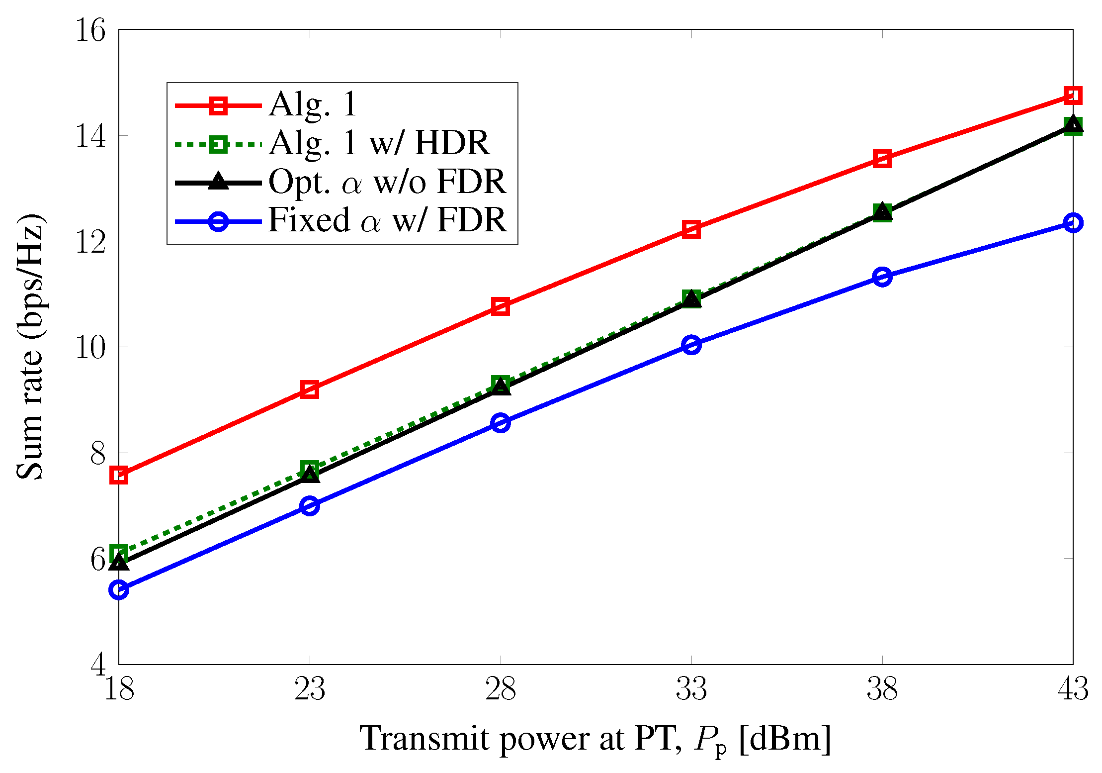
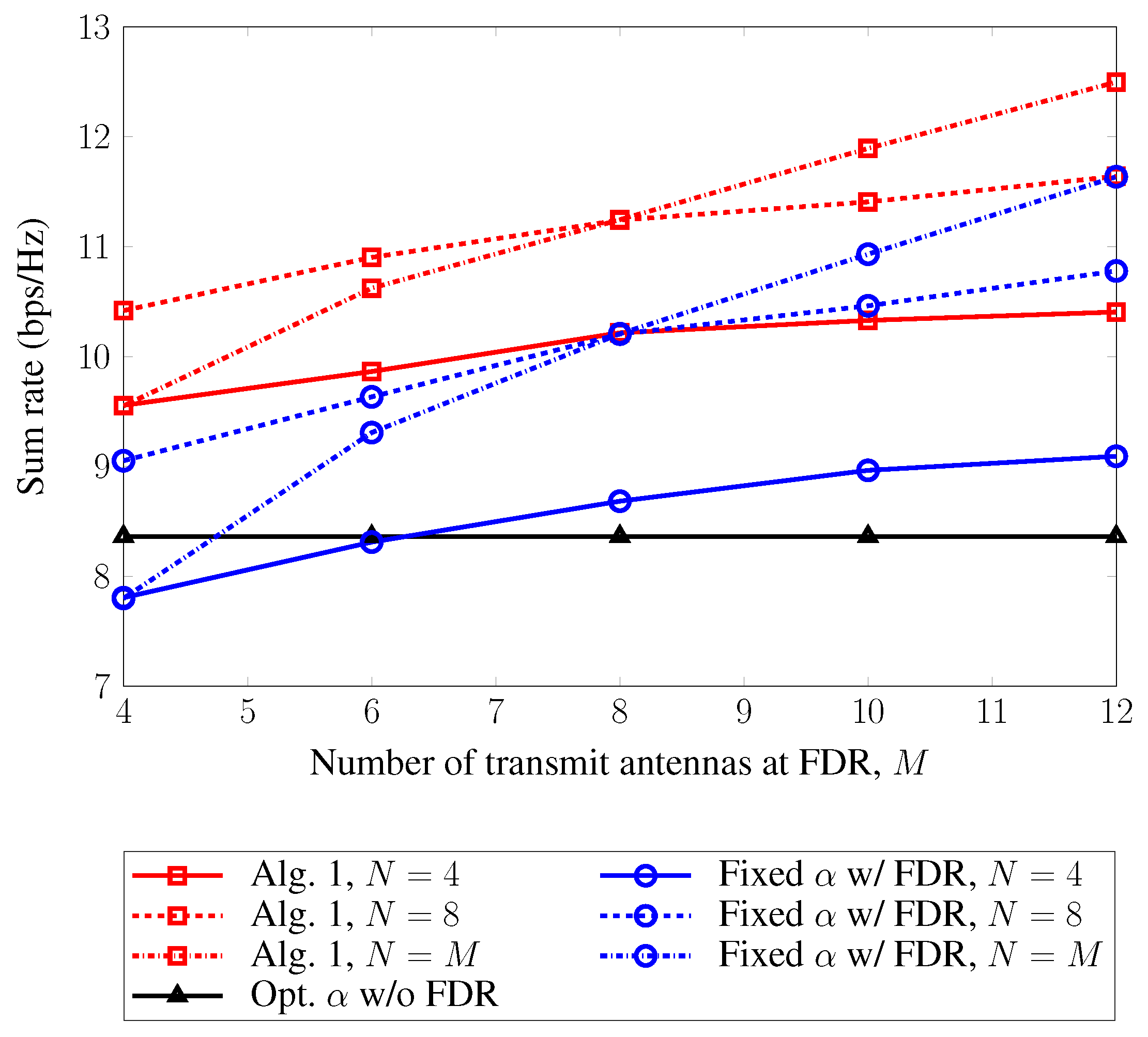
Figure 3 depicts the sum rate of SR and PR versus the maximum power budget at PT. The range of the examined power budget is from 18 to 43 dBm, which is usually used for the maximum power at BS in small-cell to macro-cell scenarios [30]. To evaluate the proposed algorithm (Algorithm 1), we consider three other schemes: (i) SR and PR directly receive the signals from ST and PT, respectively, in which the harvesting time α for ST is optimized (Opt. α w/oFDR); (ii) data transmission using the same beamforming and detection as the proposed method is performed with α fixed to 0.5 (fixed α w/FDR); (iii) we plot the performance of a baseline scheme using a half-duplex relay (HDR) (named as “Alg. 1 w/HDR”), in which the proposed algorithm is utilized to find the optimal value of α , and the later phase with time fraction ( 1 α ) is split into two sub-phases: one sub-phase for transferring signals from ST and PT to HDR and the other sub-phase for forwarding the messages from HDR to SR and PR. We can observe that the proposed method provides the best performance, due to the fact that the power is efficiently utilized by a cooperation between the harvesting time and beamforming at the FDR. In particular, for all the considered values of P p , the proposed scheme gives about 2 bps/Hz higher than the one using “fixed α w/FDR”, due to only the linear difference in time fraction optimization. Meanwhile, the gain of the proposed scheme over “Opt. α w/o FDR” decreases as P p increases. Clearly, “Opt. α w/o FDR” suffers from high attenuation, due to the long-distance propagation from PT (ST) to PR (SR), which is merely compensated by the increase in power budget at the PT. It can be observed that with a low transmit power at PT, “Alg. 1 w/HDR” slightly outperforms “Opt. α w/o FDR”, which confirms the benefit of the use of relaying. However, the performance gap is seen to diminish as P p increases. Figure 4 further investigates the system performance with various numbers of receive/transmit antennas at FDR. Obviously, the performance of the scheme without FDR is independent of the number of antennas, while the rate gain obtained by the proposed method is verified. Indeed, the performance of FDR-assisted schemes is improved more quickly when both N and M increase than when only one of them increases.
Figure 5 shows the trade-off between SR and PR rates with respect to α for different numbers of receive/transmit antennas. Considering practicability, we set the number of transmit/receive antennas at the FDR to the powers-of-two values. The energy harvested at the ST and FDR becomes higher as α increases, leading to a higher SR rate. However, when the value of α is higher than a certain threshold, the SR rate deteriorates due to the decrease in the information transmission time, ( 1 α ) . On the contrary, the PR rate increases with α , since the time of direct information transmission for the PR increases. At the maximum sum-rate point associated with the optimal α , an increase in the number of transmit antennas at the FDR ( M = 4 , 8 , 16 ) provides more degrees of freedom, which boosts both the SR and PR rates. On the other hand, the sum rate also increases as the number of receive antennas at FDR ( N = 4 , 8 , 16 ) increases. This is primarily attributed to an increase in the SR rate, as FDR would be in the proximity of ST.

5. Conclusions

In this paper, we considered a sum rate maximization problem for the primary and secondary systems assisted by an FDR with energy harvesting. A design problem based on the TSR protocol for joint optimization of energy harvesting and information transfer was established as a non-convex problem. By using the ICA framework, we derived the optimal solution for the problem. Remarkably, the proposed iterative algorithm was shown to provide a low computational complexity per iteration. Numerical results indicated that the proposed scheme and algorithm provided a spectral efficiency 0.5 to 2 bps/Hz higher than other schemes in the medium to high transmit power at PT by exploiting the benefits of multiple antennas and time fraction optimization. Moreover, we demonstrated a trade-off between the SR rate and the PR rate, as well as the effect of the number transmit and receive antennas at FDR on the sum rate.

Author Contributions

Conceptualization, H.V.N. and V.-D.N.; methodology, H.V.N., V.-D.N., and O.-S.S.; simulation, H.V.N.; validation, H.V.N., V.-D.N., and O.-S.S.; writing, original draft preparation, H.V.N.; writing, review and editing, H.V.N., V.-D.N., and O.-S.S.; supervision, O.-S.S.; project administration, O.-S.S.; funding acquisition, O.-S.S. All authors read and agreed to the published version of the manuscript.

Funding

This work was supported by the National Research Foundation of Korea (NRF) grant funded by the Korean government (MOE and MSIT) (No. 2017R1D1A1B03030436, No. 2017R1A5A1015596 and No. 2019R1A2C1084834).

Conflicts of Interest

The authors declare no conflict of interest.

Appendix A. Proof of Theorem 1

To convexify (15), we first address Constraint (15a). For two arbitrary vectors x and y , let λ ( x , y ) η P p x 2 y 2 , and then, Constraint (15a) is equivalent to the following constraints:
( 15 a ) α λ ( f p s , a s H h s ) α λ ( h p , ρ a s H H 0 W ) + β ψ ST , R 1 t s , ( A 1 a ) α λ ( h p , g s w s ) α λ ( h p , g s w p ) + β σ 2 1 t s , ( A 1 b )
where ψ ST , R P p a s H h p 2 + a s 2 σ 2 . By applying (19) to (A1), Constraint (15a) is convexified as:
g ( κ ) ( α , ν ST , R ) λ ( f p s , a s H h s ) 1 t s ,
g ( κ ) ( α , ν R , SR ) λ ( h p , g s w s ) 1 t s ,
with the imposed constraints:
α λ ( h p , ρ a s H H 0 W ) + β ψ ST , R ν ST , R ,
α λ ( h p , g s w p ) + β σ 2 ν R , SR ,
where ν ST , R and ν R , SR are new variables. When κ , the equality of (15a) holds with the equalities in (A2) and (A3), which are given in (22). Next, we apply the same steps as above to (15b) to obtain the convex constraints in (23), which completes the proof.

References

  1. Sabharwal, A.; Schniter, P.; Guo, D.; Bliss, D.W.; Rangarajan, S.; Wichman, R. In-band full-duplex wireless: Challenges and opportunities. IEEE J. Sel. Areas Commun. 2014, 32, 1637–1652. [Google Scholar] [CrossRef] [Green Version]
  2. Yadav, A.; Tsiropoulos, G.I.; Dobre, O.A. Full-Duplex Communications: Performance in Ultradense mm-Wave Small-Cell Wireless Networks. IEEE Veh. Technol. Mag. 2018, 13, 40–47. [Google Scholar] [CrossRef]
  3. Nguyen, D.; Tran, L.N.; Pirinen, P.; Latva-aho, M. On the spectral efficiency of full-duplex small cell wireless systems. IEEE Trans. Wirel. Commun. 2014, 13, 4896–4910. [Google Scholar] [CrossRef]
  4. Tam, H.H.M.; Tuan, H.D.; Ngo, D.T. Successive Convex Quadratic Programming for Quality-of-Service Management in Full-Duplex MU-MIMO Multicell Networks. IEEE Trans. Commun. 2016, 64, 2340–2353. [Google Scholar] [CrossRef]
  5. Nguyen, V.D.; Nguyen, H.V.; Nguyen, C.T.; Shin, O.S. Spectral Efficiency of Full-Duplex Multiuser System: Beamforming Design, User Grouping, and Time Allocation. IEEE Access 2017, 5, 5785–5797. [Google Scholar] [CrossRef]
  6. Nguyen, H.V.; Nguyen, V.D.; Dobre, O.A.; Wu, Y.; Shin, O.S. Joint antenna array mode selection and user assignment for full-duplex MU-MISO systems. IEEE Trans. Wirel. Commun. 2019, 18, 2946–2963. [Google Scholar] [CrossRef]
  7. Yang, K.; Cui, H.; Song, L.; Li, Y. Efficient Full-Duplex Relaying With Joint Antenna-Relay Selection and Self-Interference Suppression. IEEE Trans. Wirel. Commun. 2015, 14, 3991–4005. [Google Scholar] [CrossRef]
  8. Yu, B.; Yang, L.; Cheng, X.; Cao, R. Power and Location Optimization for Full-Duplex Decode-and-Forward Relaying. IEEE Trans. Commun. 2015, 63, 4743–4753. [Google Scholar] [CrossRef]
  9. Haykin, S.; Setoodeh, P. Cognitive Radio Networks: The Spectrum Supply Chain Paradigm. IEEE Trans. Cogn. Commun. Netw. 2015, 1, 3–28. [Google Scholar] [CrossRef]
  10. Nguyen, H.V.; Nguyen, V.-D.; Kim, H.M.; Shin, O.-S. A Convex optimization for sum rate maximization in a MIMO cognitive radio network. In Proceedings of the 2016 Eighth International Conference on Ubiquitous and Future Networks (ICUFN), Vienna, Austria, 5–8 July 2016; pp. 495–497. [Google Scholar]
  11. Erdogan, E.; Afana, A.; Ikki, S.; Yanikomeroglu, H. Antenna Selection in MIMO Cognitive AF Relay Networks with Mutual Interference and Limited Feedback. IEEE Commun. Lett. 2017, 21, 1111–1114. [Google Scholar] [CrossRef]
  12. Zheng, G.; Krikidis, I.; Ottersten, B. Full-Duplex Cooperative Cognitive Radio with Transmit Imperfections. IEEE Trans. Wirel. Commun. 2013, 12, 2498–2511. [Google Scholar] [CrossRef] [Green Version]
  13. Mohammadi, M.; Chalise, B.K.; Hakimi, A.; Mobini, Z.; Suraweera, H.A.; Ding, Z. Beamforming Design and Power Allocation for Full-Duplex Non-Orthogonal Multiple Access Cognitive Relaying. IEEE Trans. Commun. 2018, 66, 5952–5965. [Google Scholar] [CrossRef]
  14. Ali, B.; Mirza, J.; Zhang, J.; Zheng, G.; Saleem, S.; Wong, K. Full-Duplex Amplify-and-Forward Relay Selection in Cooperative Cognitive Radio Networks. IEEE Trans. Veh. Technol. 2019, 68, 6142–6146. [Google Scholar] [CrossRef] [Green Version]
  15. Lee, S.; Zhang, R.; Huang, K. Opportunistic wireless energy harvesting in cognitive radio networks. IEEE Trans. Wirel. Commun. 2013, 12, 4788–4799. [Google Scholar] [CrossRef] [Green Version]
  16. Shi, Q.; Liu, L.; Xu, W.; Zhang, R. Joint transmit beamforming and receive power splitting for MISO SWIPT systems. IEEE Trans. Wirel. Commun. 2014, 13, 3269–3280. [Google Scholar] [CrossRef] [Green Version]
  17. Khandaker, M.; Wong, K.K. SWIPT in MISO Multicasting Systems. IEEE Wirel. Commun. Lett. 2014, 3, 277–280. [Google Scholar] [CrossRef]
  18. Bhowmick, A.; Yadav, K.; Roy, S.D.; Kundu, S. Throughput of an Energy Harvesting Cognitive Radio Network Based on Prediction of Primary User. IEEE Trans. Veh. Technol. 2017, 66, 8119–8128. [Google Scholar] [CrossRef]
  19. Ponnimbaduge Perera, T.D.; Jayakody, D.N.K.; Sharma, S.K.; Chatzinotas, S.; Li, J. Simultaneous Wireless Information and Power Transfer (SWIPT): Recent Advances and Future Challenges. IEEE Commun. Surv. Tutor. 2018, 20, 264–302. [Google Scholar] [CrossRef] [Green Version]
  20. Gao, Y.; He, H.; Deng, Z.; Zhang, X. Cognitive Radio Network with Energy-Harvesting Based on Primary and Secondary User Signals. IEEE Access 2018, 6, 9081–9090. [Google Scholar] [CrossRef]
  21. Zhai, D.; Zhang, R.; Du, J.; Ding, Z.; Yu, F.R. Simultaneous Wireless Information and Power Transfer at 5G New Frequencies: Channel Measurement and Network Design. IEEE J. Sel. Areas Commun. 2019, 37, 171–186. [Google Scholar] [CrossRef]
  22. Nguyen, V.D.; Duong, T.Q.; Tuan, H.D.; Shin, O.S.; Poor, H.V. Spectral and Energy Efficiencies in Full-Duplex Wireless Information and Power Transfer. IEEE Trans. Commun. 2017, 65, 2220–2233. [Google Scholar] [CrossRef] [Green Version]
  23. Bhowmick, A.; Roy, S.D.; Kundu, S. Throughput of a Cognitive Radio Network with Energy-Harvesting Based on Primary User Signal. IEEE Wirel. Commun. Lett. 2016, 5, 136–139. [Google Scholar] [CrossRef]
  24. Xing, H.; Kang, X.; Wong, K.; Nallanathan, A. Optimizing DF Cognitive Radio Networks With Full-Duplex-Enabled Energy Access Points. IEEE Trans. Wirel. Commun. 2017, 16, 4683–4697. [Google Scholar] [CrossRef] [Green Version]
  25. Riihonen, T.; Werner, S.; Wichman, R. Mitigation of loopback self-interference in full-duplex MIMO relays. IEEE Trans. Signal Process. 2011, 59, 5983–5993. [Google Scholar] [CrossRef]
  26. Duarte, M.; Dick, C.; Sabharwal, A. Experiment-driven characterization of full-duplex wireless systems. IEEE Trans. Wirel. Commun. 2012, 11, 4296–4307. [Google Scholar] [CrossRef] [Green Version]
  27. Nguyen, V.D.; Nguyen, H.V.; Dobre, O.A.; Shin, O.S. A New Design Paradigm for Secure Full-Duplex Multiuser Systems. IEEE J. Sel. Areas Commun. 2018, 36, 1480–1498. [Google Scholar] [CrossRef]
  28. Bhowmick, A.; Chatterjee, A.; Verma, T. Performance of DF Relaying in an Energy Harvesting Full Duplex Cognitive Radio Network. In Proceedings of the 2019 International Conference on Vision Towards Emerging Trends in Communication and Networking (ViTECoN), Vellore, India, 30–31 March 2019; pp. 1–4. [Google Scholar]
  29. Korpi, D.; Heino, M.; Icheln, C.; Haneda, K.; Valkama, M. Compact Inband Full-Duplex Relays With Beyond 100 dB Self-Interference Suppression: Enabling Techniques and Field Measurements. IEEE Trans. Antennas Propag. 2017, 65, 960–965. [Google Scholar] [CrossRef]
  30. 3GPP Technical Specification Group Radio Access Network, Evolved Universal Terrestrial Radio Access (E-UTRA): Further Advancements for E-UTRA Physical Layer Aspects (Release 9); Document 3GPP TS 36.814 V9.0.0; 3GPP: Valbonne, France, 2010.
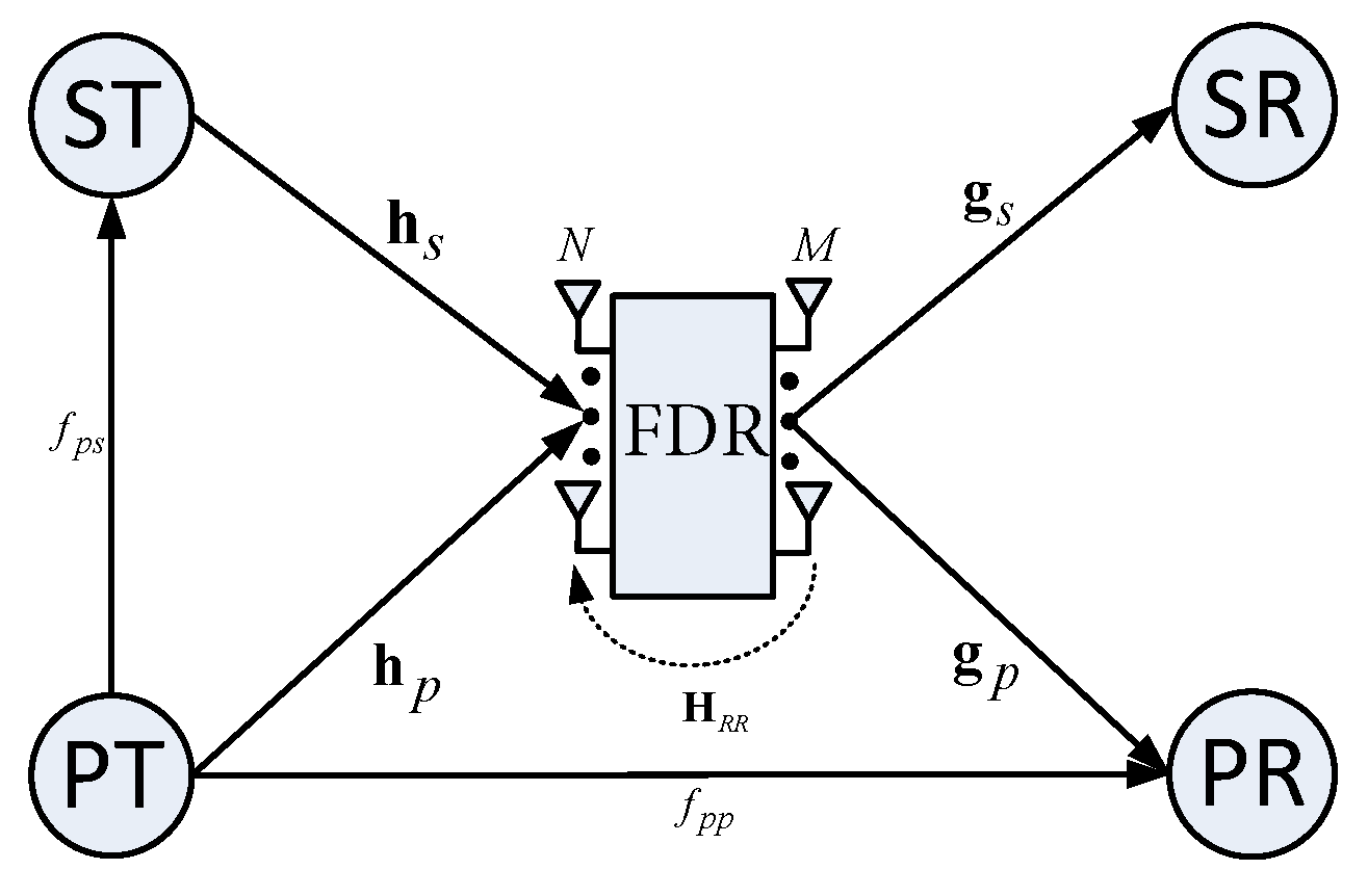
Figure 1. A cognitive radio network with a full-duplex relay (FDR).
Electronics 09 00835 g001
Figure 2. Time-switching relaying (TSR) protocol.
Electronics 09 00835 g002
Figure 3. Sum rate of the secondary receiver (SR) and the primary receiver (PR) versus P p with M = N = 4 .
Electronics 09 00835 g003
Figure 4. Sum rate of SR and PR versus the transmit power at the primary transmitter (PT) and the number of antennas at the full-duplex relay (FDR).
Electronics 09 00835 g004
Figure 5. Trade-off between SR and PR rates.
Electronics 09 00835 g005