Article

Compensation Parameters Optimization of Wireless Power Transfer for Electric Vehicles

1
School of Automation, Nanjing University of Science and Technology, Nanjing 210094, China
2
Jiangsu Provincial Key Laboratory of Smart Grid Technology and Equipment, Nanjing 210096, China
*
Author to whom correspondence should be addressed.
Electronics 2020, 9(5), 789; https://doi.org/10.3390/electronics9050789
Submission received: 16 March 2020 / Revised: 6 May 2020 / Accepted: 7 May 2020 / Published: 11 May 2020
(This article belongs to the Special Issue Wireless Power/Data Transfer, Energy Harvesting System Design)

Abstract

:
For wireless charging of electric vehicles (EVs), increasing the output power level is particularly important. In this paper, the purpose of improving the output power while maintaining optimal transmission efficiency is achieved by optimizing the parameters of the compensation topology under the premise that the coupled coils of the system does not need to be redesigned. The series-series (SS) and hybrid-series-parallel (LCC, composed by an inductor and two capacitors) compensation topology are studied. The influence factors of load resistance to achieve optimal efficiency, the influence of LCC compensation parameters on the power output level, and the influence of parameter changes on system safety are analyzed. Theorical results show that by rationally designing the LCC compensation parameters, larger output power and optimal transfer efficiency can be achieved under different load resistance by adjusting the inductances of the primary and secondary compensation circuits. The output power of the optimized system with adjusted LCC compensation topology is increased by 64.2% with 89.8% transfer efficiency under 50 ohms load in experiments. The correctness and feasibility of this parameter design method are verified by both theorical and experimental results.

1. Introduction

Since the concept of magnetic coupled resonant wireless power transfer (MCR-WPT) was proposed by MIT in 2007, the technology has developed rapidly and has been widely applied in implantable medical devices, home appliances, mobile devices and electric vehicles [1,2,3,4,5,6,7,8]. Increasing transmission power is particularly important for wireless charging of electric vehicles. The main ways to improve power levels are: (1) power supply parallel topology, which uses multiple parallel power supplies for power distribution, but the parallel topology is too redundant [9]; (2) multi-phase parallel, there are shortcomings of current imbalance between phases and serious coil loss. In addition, the compensation topology also has a great impact on the output power level.
At present, the basic compensation topologies are series-series (SS), series-parallel (SP), parallel-series (PS), and parallel-parallel (PP) [10,11]. The most widely used is the SS topology, but this topology has inherent disadvantages: once coil parameters are determined, the rated output power can be regulated only by the input voltage. In addition to the four basic resonance topologies described above, hybrid-series-parallel (LCC, composed by an inductor and two capacitors) compensation topology has been extensively studied for its excellent performance. It can implement zero phase angle (ZPA) and zero voltage switching (ZVS), and its output current is independent of the load [12,13,14,15,16,17].
Most of the current studies on WPT compensation topology focus on improving the output performance by adopting complex control strategies. However, the load resistance to achieve optimal efficiency of SS topology WPT system is unchangeable after the coil-parameters are fixed whereas the one of LCC topology can be adjusted according to the parameters of compensation topology. In this paper, the WPT system is modeled and the transfer performance is analyzed. Methods are proposed to increase output power level while maintaining optimal transmission efficiency without redesign of the coupled coils by optimizing the parameters of LCC compensation topology. Both theorical and experimental results indicate that the proposed parameter optimization strategy is effective in improving transfer efficiency and adjusting output power under different load resistances. It avoids the disadvantages of redesigning the coil due to power level changes to maintain high transmission efficiency. At the same time, it has obvious advantages in safety under the condition of output short circuit.

2. Theoretical Analysis

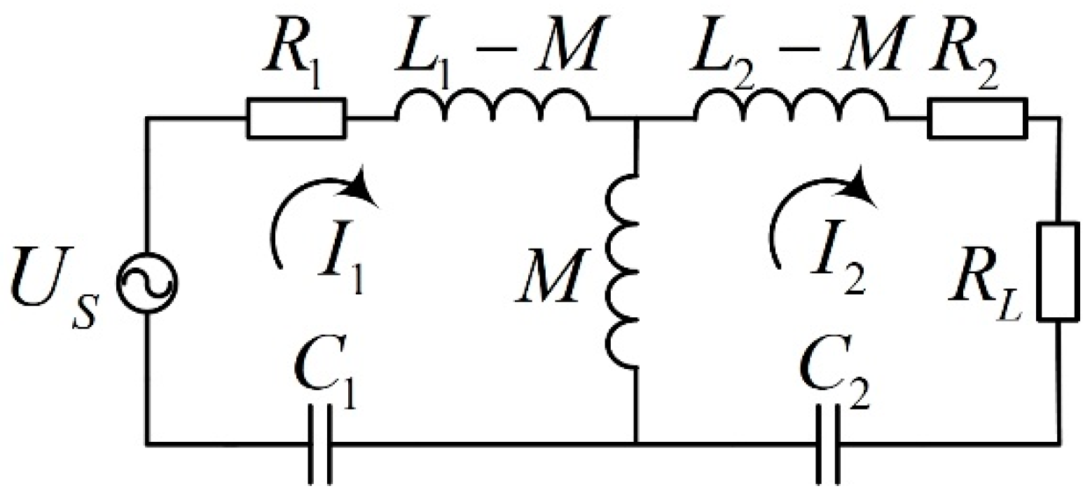
2.1. System Analysis

Figure 1 shows the schematic diagram of the magnetic coupled wireless power transfer system, where AC power on the grid side is rectified to form DC power, the high-frequency inverter is composed of H-bridge, and the direct current is converted by inverter circuit into alternating current with a system rated frequency, which flows through the transmitter end and transmits the power to the receiver coil. The primary and secondary compensation circuit is composed of SS or LCC compensation topology. The transmitter and receiver coils are planar spiral coils designed in Section 3, and the receiver end is connected to electric vehicle battery through a rectifier circuit.
Because the resonance part of wireless power transfer system has the characteristics of band-pass filtering, only the fundamental wave component is considered later, and the square wave generated by the full-bridge inverter can be equivalent to an AC voltage source for theoretical analysis. The square wave is expanded according to the Fourier series, the duty cycle is set to D, and the fundamental wave of the square wave whose amplitude is Ud is as follow:
f t = 4 U d π sin ( π D ) cos ( ω t π D )
The battery is a typical non-linear load. With the use of battery, the battery charging current and the state of charge are different, and different external load characteristics are displayed. In order to simplify the difficulty of system analysis, the battery is generally equivalent to a resistive load according to the ratio of charging voltage and current of battery and then analyzed. Therefore, the battery and its management system are equivalent to a load in this paper.

2.2. Theoretical Analysis of SS and LCC Compensation Topology

Modeling and analysis of SS-type and LCC-type compensation topologies are shown below. Figure 2 and Figure 3 show simplified topologies of SS-type and LCC-type resonant circuits, respectively. The parasitic resistance of inductors and capacitors are much smaller than the internal resistance of coil, so it can be ignored. The subsequent experimental results show that this approximate analysis does not affect the accuracy of experiment.

2.2.1. Analysis of SS-type Resonance Circuit

The SS topology is the most basic resonance structure. Both primary and secondary side use series resonance. The equivalent circuit is shown in Figure 2, where US is a voltage-stabilized source, the source internal resistance is ignored, M is the mutual inductance between two coils.
According to Figure 2 and Kirchhoff voltage law (KVL), we can obtain:
{ ( R 1 + j ω L 1 + 1 j ω C 1 ) I ˙ 1 j ω M I ˙ 2 = U ˙ s ( R 2 + R L + j ω L 2 + 1 j ω C 2 ) I ˙ 2 j ω M I ˙ 1 = 0
When the system meets the resonance conditions:
f 0 = 1 2 π L 1 C 1 = 1 2 π L 2 C 2
When RL is much greater than R1 and R2, R1 and R2 can be ignored, the currents are as follows:
{ I 1 = U s R L ( ω M ) 2 I 2 = U s ω M
The transmission power and efficiency of the system are:
P s s = U s 2 R L ( ω M ) 2
η s s = 1 R L R 1 ( ω M ) 2 R 2 R L
The maximum efficiency and corresponding load value are:
η s s _ max = 1 2 R 1 R 2 ω M
R s s = R 2 R 1 ( ω M ) 2
Due to the inverse relationship between distance and mutual inductance, in practical applications, it is common for charging object to be far away from primary coil. It can be seen from (4) and (5) that when the secondary side is open, the primary current will increase sharply; when a short circuit occurs on the secondary side, the primary current and transmission power will decrease. On the other hand, in the case of the SS structure with constant coil parameters, the load resistance to achieve optimal efficiency is unchangeable.

2.2.2. Analysis of LCC-type Resonance Circuit

The LCC structure is a new type of composite resonant structure. As shown in Figure 3, Lf1, C1, Cp1 and Lf2, C2, Cp2 are the corresponding resonant circuit units of primary and secondary coils, respectively.
Similarly, we can formulate KVL equation according to Figure 3:
{ ( j ω L f 1 + 1 j ω C 1 ) I ˙ 1 1 j ω C 1 I ˙ 2 = U ˙ s ( R 1 + j ω L 1 + 1 j ω C 1 + 1 j ω C p 1 ) I ˙ 2 1 j ω C 1 I ˙ 1 j ω M I ˙ 3 = 0 ( R 2 + j ω L 2 + 1 j ω C 2 + 1 j ω C p 2 ) I ˙ 3 1 j ω C 2 I ˙ 4 j ω M I ˙ 2 = 0 ( R L + j ω L f 2 + 1 j ω C 2 ) I ˙ 4 1 j ω C 2 I ˙ 3 = 0
The resonance conditions are as follows:
C 1 = 1 ω 2 L f 1 , C p 1 = 1 ω 2 L 1 1 C 1 , C 2 = 1 ω 2 L f 2 , C p 2 = 1 ω 2 L 2 1 C 2
The currents of the loops are:
{ I 1 = ω 6 C 1 2 C 2 2 M 2 R L U s I 2 = ω C 1 U s I 3 = ω 4 C 1 C 2 2 M R L U s I 4 = ω 3 C 1 C 2 M U s
The transmission power and efficiency of the system are:
P L C C = M 2 U s 2 R L ω 2 L f 1 2 L f 2 2
η L C C = 1 R 1 L f 2 2 R L M 2 R 2 R L ω 2 L f 2 2
The maximum efficiency and corresponding load values are:
η L C C _ max = 1 2 R 1 R 2 ω M
R L C C = R 1 ω 2 L f 2 4 R 2 M 2 = R 1 L f 2 2 R 2 M 2 R S S
It can be known from (11) that when the mutual inductance decreases, the currents of primary and secondary coils decrease, which is a safe working condition. And when the system coil-parameters are fixed, the load resistance to achieve optimal efficiency can be adjusted by the inductance of the secondary resonance circuit Lf2. C2 also needs to be adjusted to keep resonant according to (10). Compared with the SS structure, it avoids the disadvantages of redesigning the coil parameters to maintain efficient operation when the system’s rated parameters are changed, which makes the system design more flexible and reduces the manufacturing cost.

3. Parameter Design

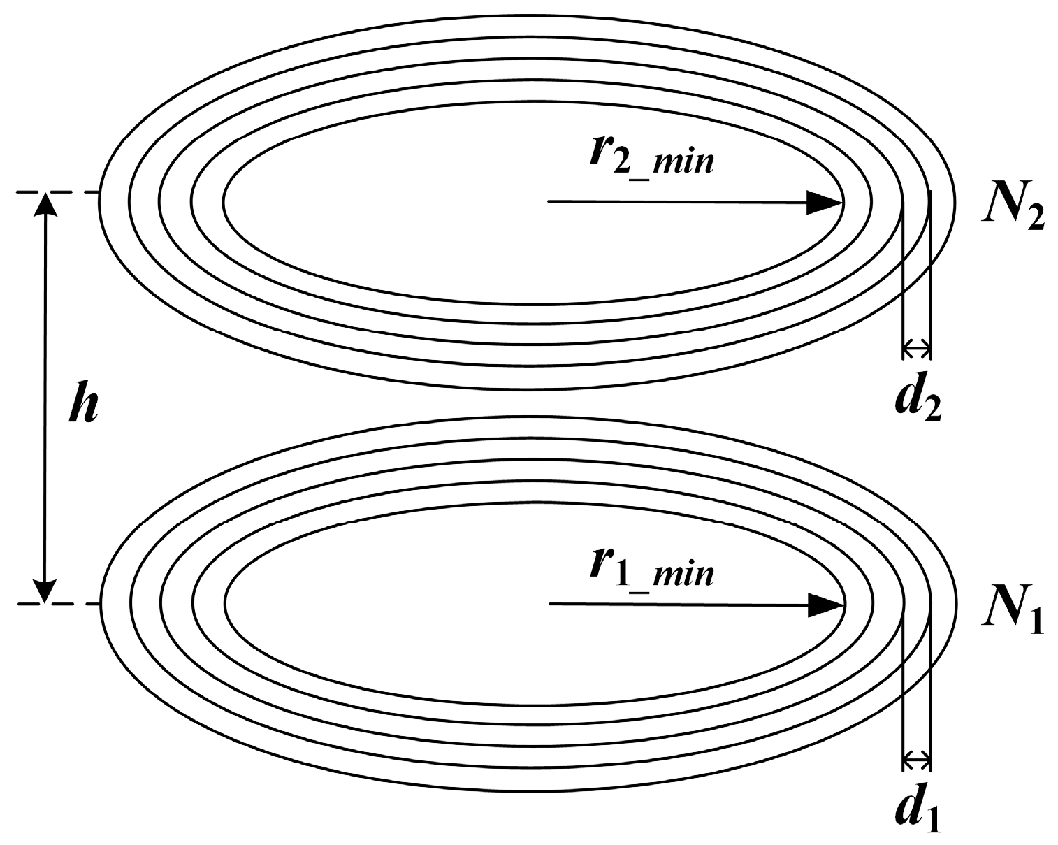
3.1. Effect of Coil Design on Optimal Efficiency Load

When a WPT system is actually designed, some parameters are fixed due to the limitation of frequency or coil size. At this time, choosing a specific resonance mode to obtain better transmission efficiency according to the existing parameters becomes the key to the design.
This paper presents a design scheme of planar spiral coil [18] that optimizes the system transmission efficiency. The core idea of designing a high-efficiency MCR-WPT system is to maintain the system’s high-efficiency operating state by adjusting the other coil parameters (mainly turn number, wire diameter, turn pitch, etc.) when the rated load is the optimal load to achieve maximum efficiency.
Figure 4 is a schematic diagram of planar spiral coil. The internal resistance R, self-inductance L and mutual inductance M between the coils [19,20,21] can be obtained by:
{ R = ρ μ 0 ω 2 N r a v g a L = μ 0 N 2 r a v g c 1 [ ln ( c 2 / λ ) + c 3 λ + c 4 λ 2 ] M = μ 0 π N 1 N 2 ( r 1 _ a v g 2 ) 2 ( r 2 _ a v g 2 ) 2 2 [ h 2 + ( r 1 _ a v g 2 ) 2 ] 1.5
where ρ is the conductor resistivity, μ0 is the vacuum permeability, ω is the current angular frequency, N is the number of coil turns, rmin is the inner radius of coil, d is the turn spacing of coil, ravg = rmin + (N − 1)d/2 is the average radius of coil, a is the conductor radius, c1, c2, c3 and c4 are fitting coefficients, for circular coils they are 1, 2.46, 0 and 0.2, respectively, λ = (N − 1)d/(2*ravg), h is the transmission distance.
According to the actual application scenario, some parameters of the system can be determined. In this paper, the transmission distance h = 20cm, the inner radius of the transmitter and receiver coil r1_min = r2_min = 2 cm. In the case of tightly wound, the conductor diameter and turn spacing are not considered, the influence of coil turns on transmission efficiency occupies the main factor. Where the load resistance RL is optimal to realize maximum transmission efficiency, the coupling coefficient k = M/ L 1 L 2 , self-inductance L1 and L2, the coil internal resistance R1 and R2, and the optimal load RL are all related to the turn number of primary coil N1 and secondary coil N2:
{ P L = ς ( k ( N 1 , N 2 ) , L 1 ( N 1 ) , L 2 ( N 2 ) , R 1 ( N 1 ) , R 2 ( N 2 ) , R L ( N 1 , N 2 ) ) η = ξ ( k ( N 1 , N 2 ) , L 1 ( N 1 ) , L 2 ( N 2 ) , R 1 ( N 1 ) , R 2 ( N 2 ) , R L ( N 1 , N 2 ) )
(17) shows that the transmission power PL and efficiency η are quantities related to the coupling coefficient, load value, self-inductance, and coil internal resistance. Under the tightly wounding condition, the independent variable is mainly affected by the turn number of the coils. Therefore, the ultimate optimization goal of this paper can be expressed as finding the optimal coil turn number while meeting the rated power value of the system design, that is, to find max(η(N1,N2)).
Figure 5 can be made by Equation (16). It can be seen from Figure 5a that the transmission power decreases with increasing turns; from Figure 5b, the efficiency increases quickly first, then slowly increases as the turn number increases, only when the turn number of primary and secondary coils reaches a critical point can the efficiency be maintained at a higher level. Finally, the iterative method is used to obtain the number of turns, and the coil parameters are reasonably designed to achieve a high-efficiency transmission system that meets the power requirements. The specific design process is shown in Figure 6.
The following Table 1 shows the optimized resonant parameters of SS compensation topology designed to the load (50 Ω) corresponding to optimal efficiency point.

3.2. Selection of LCC Resonance Parameters

By optimizing the coil design, for the SS resonance structure, the system is in an optimal efficiency condition when the load is 50 ohms. According to (15), after the coil parameters of LCC resonance structure are determined, the optimal efficiency load value is only related to the parameter Lf2. The optimal efficiency load of LCC resonance structure can be determined by designing the inductance Lf2. From (5) and (12), we have:
P L C C = M 4 L f 1 2 L f 2 2 P S S
For the LCC resonance structure, since the load and coil parameters have been determined, it can be known that by adjusting the value of Lf1, the level of rated output power can be changed. The parameter configuration method is as follows: (1) Firstly, according to the design parameters of SS compensation structure system, the value of Lf2 is obtained by Equation (15); (2) Secondly, according to the rated power of system, determine the value Lf1 through Equation (18); (3) Finally, determine the remaining parameter values according to Equation (10).
As the rated output power of SS resonant structure is 2 kW, a margin of 0.85 is taken, and the rated output power of LCC resonant structure is 2.45 kW, so the values of two inductors Lf1 and Lf2 can be determined. The specific parameter values are as follows in Table 2.

4. Simulation and Experimental Verification

4.1. Magnetic Simulation
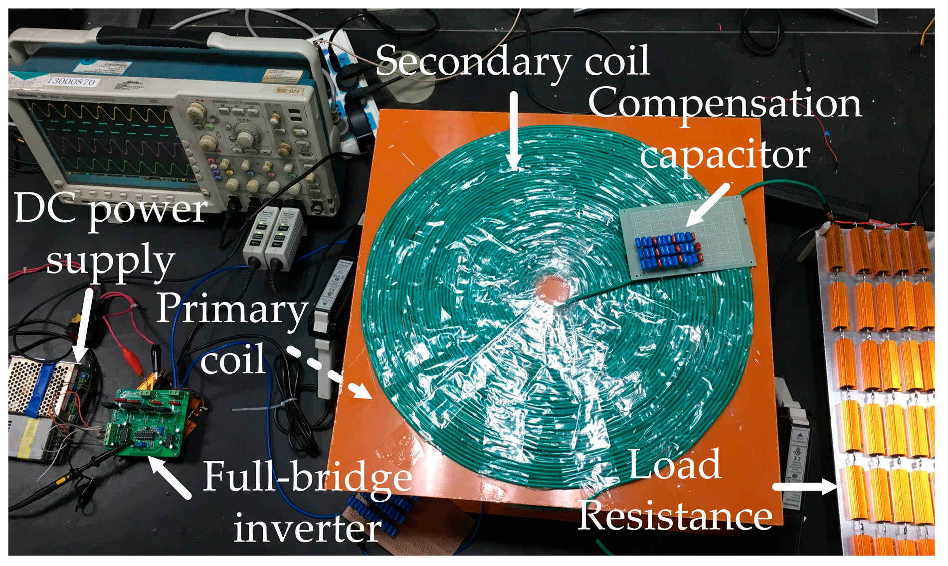
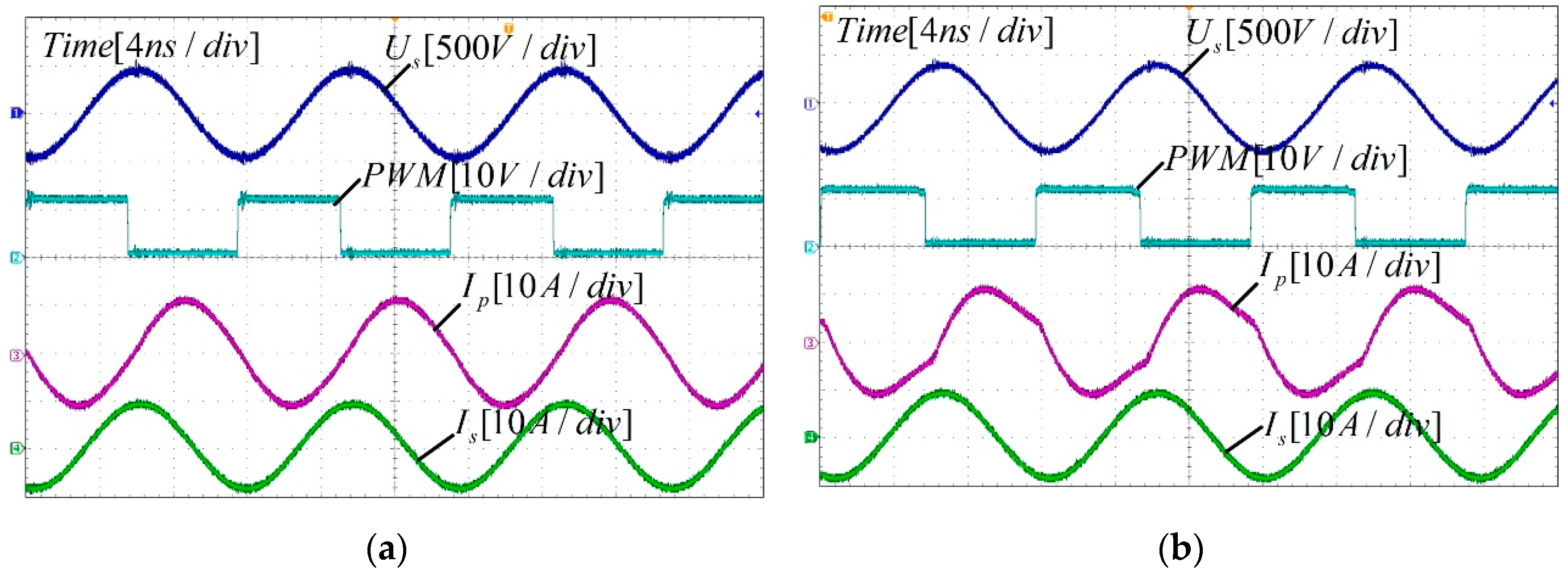
For the coil designed in Section 3, the finite element simulation software ANSYS EM was used for simulation, and the vertical distance between two coils was 200 mm, the remaining parameters are shown in Table 1 and Table 2. The 3D finite element model is shown in Figure 7a, the boundary condition is radiation, the excitation currents Ip = 7A and Is = 7A, the maximum mesh element lengths of solution region, transmitter and receiver coil are 75 mm, 40 mm and 40 mm, respectively. Figure 7b is the distribution diagram of magnetic field strength around the system. It can be seen that the magnetic field distribution around the system is evenly distributed, mainly concentrated near the coils, and has little effect on the surrounding environment.
Another purpose of simulation is to obtain the self-inductance, mutual inductance and coupling coefficient of the coil. There are many theoretical calculation methods for calculating these parameters, which will not be repeated here. They can also be obtained by actual measurement. According to the SAEJ2954 standard [22], the actual measured coupling coefficient formula is:
k = V o c I s c / V 1 I 1
where, V1 and I1 are the voltage and current of primary coil respectively, Voc and Isc are the open circuit voltage and short circuit current of secondary coil, respectively.
The actual mutual inductance value can be obtained by “open circuit and short circuit test”. This method needs to measure three quantities, Lp1 is the measured primary inductance when the secondary circuit is open, Ls1 is the measured secondary inductance when the primary circuit is open, and Lp2 is the measured primary inductance when the secondary circuit is shorted, as follow:
M = ( L p 1 L p 2 ) L s 1
Table 3 shows the theoretical, simulated and actual measured parameter values of the system under rated parameters. It can be seen from Table 3 that the deviation of the theoretical, simulated and actual value of the primary and secondary coil self-inductance can be ignored.

4.2. Experiment

The experimental setup is shown in Figure 8, the experimental parameters of compensation circuit are generally consistent with Table 1 and Table 2. The coils are planner spiral coil wound by Litz wire, and tightly wound with the turn spacing d = 2a, the conductor radius a = 1.8 mm, the inner radius of the transmitter and receiver coil r1_min = r2_min = 2 cm, the out radius of the transmitter r1_max = 20 cm, the out radius of the receiver r2_max = 19.28 cm. The quality factor of the transmitter and receiver coil are 612 and 623, respectively. The gate drive signal of full-bridge inverter circuit can achieve frequency adjustment, and its duty cycle is 0.5. In the resonance state, the input power can be obtained from the input voltage value and input current value of rectifier bridge. The output power is obtained by measuring the load voltage with a differential probe and measuring the output current with a current probe. Considering that the voltage on the capacitor at resonance is Q (quality factor) times the voltage on the circuit, the tuning capacitor is composed of CBB capacitor series and parallel.
A comparative experiment is performed for SS and LCC compensation topologies. Figure 9 shows the experimental waveforms of SS and LCC under the system’s optimal efficiency load. In Figure 9b, the primary current shows wonky parts. This is because LCC compensation topology is more complicated than SS, and the coil winding and capacitance matching errors are larger, which results in the failure to realize ideal resonance at the rated frequency. Therefore, the IP waveform of LCC structure is not as stable as the SS structure.
As can be seen from Table 4, the actual system operating efficiency and output power are basically consistent with the design goals. It illustrates the correctness of the above design method. The error between experimental results and simulation values is due to the fact that the actual system cannot fully work in the ideal state, the coil and resonant capacitor cannot be perfectly matched at the rated frequency in experiment. It is verified through experiments that the output power is increased by 13.5% under the same input voltage without a significant decrease in efficiency.
Table 5 shows the experimental data of the power and efficiency of the SS and LCC compensation topology under different loads. It can be seen from Table 5 that both SS and fixed LCC compensated WPT system achieve maximum efficiency at 50 ohms load, which is consistent with theoretical analysis. By adjusting the parameters of LCC compensation topology according to the load resistances, the output power and transfer efficiency of the adjusted LCC compensated WPT system are improved and more stable under different loads.
Based on the experiment of transmission distance change under SS and LCC structures, Figure 10 was produced. When the transmission distance changes, the system resonance frequency remains unchanged, so as to observe the vertical offset stability of the system under SS and LCC structures. It can be seen from Figure 10 that for the SS resonant topology, the input current and output current increase with distance; for the LCC structure, the input and output current decrease with distance. In practical applications, this positive correlation of the SS structure is very dangerous.
There is a deviation between the theoretical and experimental current values, the main reason is that the mutual inductance measured by the actual wound coil is smaller than the theoretical value. However, the current trend is basically the same.

5. Conclusions

In this paper, the optimal transfer efficiency of the WPT system under certain load resistance is achieved by optimizing the coil-turns number. Once the coupled coil-parameters are fixed, the load resistance to make the optimal efficiency can be adjusted and the output power can be increased by optimization design of the parameters of LCC compensation topology. The major contributions of this paper are as follows:
(1)
The method is proposed to keep the optimal transfer efficiency of the WPT system under different load resistances by adjusting the inductance value of the LCC compensate topology Lf1.
(2)
The method is proposed to increase the output power of the WPT system to satisfy more power requirements by adjusting the inductance value of the LCC compensate topology Lf2.
(3)
The optimized LCC compensated WPT system has significant advantages over the SS type. There’s no need to redesign the coupled coils to maintain transmission power and efficiency under different power levels and transfer distance. When the load resistance equals 50 Ω, the output power of the optimized WPT system is increased by 64.2% with 89.8% transfer efficiency.

Author Contributions

F.W. conceived and designed the study, and this work was performed under the advice of and regular feedback from him. X.C. and Q.L. was responsible for the models, simulations and X.C. wrote the article. W.G. was responsible for the experiments and data analysis. All authors have read and agreed to the published version of the manuscript.

Funding

This work was supported by the Basic Research Program of Jiangsu Province (No. BK20180485), Jiangsu Provincial Key Laboratory of Smart Grid Technology and Equipment Project, and the Fundamental Research Funds for the Central Universities (No. 30919011241).

Conflicts of Interest

The authors declare no conflict of interest. The funders had no role in the design of the study; in the collection, analyses, or interpretation of data; in the writing of the manuscript, or in the decision to publish the results.

References

  1. Kurs, A.; Karalis, A.; Moffatt, R. Wireless power transfer via strongly coupled magnetic resonances. Science 2007, 317, 83–86. [Google Scholar] [CrossRef] [PubMed] [Green Version]
  2. Abid, A.; O’Brien, J.; Bensel, T. Wireless Power Transfer to Millimeter-Sized Gastrointestinal Electronics Validated in a Swine Model. Sci. Rep. 2017, 7, 46745. [Google Scholar] [CrossRef] [PubMed]
  3. Roshan, Y.M.; Park, E.J. Design Approach for a Wireless Power Transfer System for Wristband Wearable Devices. IET Power Electron. 2017, 10, 931–937. [Google Scholar] [CrossRef]
  4. Patil, D.; McDonough, M.K.; Miller, J.M. Wireless Power Transfer for Vehicular Applications: Overview and Challenges. IEEE Trans. Transp. Electrif. 2018, 4, 3–37. [Google Scholar] [CrossRef]
  5. Yang, W.; Gao, Y.; Farley, K.B. EV usage and city planning of charging station installations. In Proceedings of the 2015 IEEE Wireless Power Transfer Conference (WPTC), Boulder, CO, USA, 13–15 May 2015; pp. 1–4. [Google Scholar]
  6. Bu, Y.; Endo, S.; Mizuno, T. Improvement in the Transmission Efficiency of EV Wireless Power Transfer System Using a Magnetoplated Aluminum Pipe. IEEE Trans. Magn. 2018, 54, 1–5. [Google Scholar] [CrossRef]
  7. Elnait, K.E.I.; Huang, L.; Tan, L. Resonant Reactive Current Shield Design in WPT Systems for Charging EVs. In Proceedings of the 2018 IEEE PES Asia-Pacific Power and Energy Engineering Conference (APPEEC), Kota Kinabalu, Malaysia, 7–10 October 2018; pp. 56–59. [Google Scholar]
  8. Li, W.; Wang, Q.; Wang, Y. Three-dimensional rotatable omnidirectional MCR WPT systems. IET Power Electron. 2020, 13, 256–265. [Google Scholar] [CrossRef]
  9. Hao, H.; Covic, G.A.; Boys, J.T. A Parallel Topology for Inductive Power Transfer Power Supplies. IEEE Trans. Power Electron. 2014, 29, 1140–1151. [Google Scholar] [CrossRef]
  10. Liu, F.; Zhang, Y.; Chen, K. A comparative study of load characteristics of resonance types in wireless transmission systems. In Proceedings of the 2016 Asia-Pacific International Symposium on Electromagnetic Compatibility, APEMC 2016, Shenzhen, China, 17–21 May 2016; Volume 01, pp. 203–206. [Google Scholar]
  11. Villa, J.L.; Sallan, J.; Osorio, J.F.S. High-Misalignment Tolerant Compensation Topology for ICPT Systems. IEEE Trans. Ind. Electron. 2011, 59, 945–995. [Google Scholar] [CrossRef]
  12. Shen, D.; Du, G.; Zeng, W. Research on Optimization of Compensation Topology Parameters for a Wireless Power Transmission System with Wide Coupling Coefficient Fluctuation. IEEE Access. 2020, 8, 59648–59658. [Google Scholar] [CrossRef]
  13. Chen, Y.; Yang, N.; Liu, L. Two/Three-Coil Hybrid Topology for WPT Systems Charging Electric Bicycles. In Proceedings of the 2019 IEEE Applied Power Electronics Conference and Exposition (APEC), Anaheim, CA, USA, 17–21 March 2019; pp. 3084–3087. [Google Scholar]
  14. Jenson, J.; Therattil, J.P.; Johnson, J.A. A Novel LCC-LCL Compensation WPT System for Better Performance. In Proceedings of the 2019 IEEE International Conference on Electrical, Computer and Communication Technologies (ICECCT), Coimbatore, India, 20–22 February 2019; pp. 1–6. [Google Scholar]
  15. Mai, R.; Chen, Y.; Zhang, Y. Optimization of the Passive Components for an S-LCC Topology-Based WPT System for Charging Massive Electric Bicycles. IEEE Trans. Ind. Electron. 2018, 65, 5497–5508. [Google Scholar] [CrossRef]
  16. Zhang, H.; Lu, F. An improved design methodology of the double-sided LC-Compensated CPT system considering the inductance detuning. IEEE Trans. Power Electron. 2019, 34, 11396–11406. [Google Scholar] [CrossRef]
  17. Li, S.; Li, W.; Deng, J. A Double-Sided LCC Compensation Network and Its Tuning Method for Wireless Power Transfer. IEEE Trans. Veh. Technol. 2015, 64, 2261–2273. [Google Scholar] [CrossRef]
  18. Kiani, M.; Ghovanloo, M. A Figure-of-Merit for Designing High-Performance Inductive Power Transmission Links. IEEE Trans. Ind. Electron. 2013, 60, 5292–5305. [Google Scholar] [CrossRef] [PubMed]
  19. Balanis, C.A. Antenna Theory: Analysis and Design, 3rd ed.; Wiley-Interscience: Hoboken, NJ, USA, 2005. [Google Scholar]
  20. Mohan, S.S.; Del Mar Hershenson, M.; Boyd, S.P. Simple Accurate Expressions for Planar Spiral Inductances. IEEE J. Solid-State Circuits 1999, 34, 1419–1424. [Google Scholar] [CrossRef] [Green Version]
  21. Wei, W.; Kawahara, Y.; Kobayashi, N. Characteristic Analysis of Double Spiral Resonator for Wireless Power Transmission. IEEE Trans. Antennas Propag. 2014, 62, 411–419. [Google Scholar] [CrossRef]
  22. SAE J2954: Wireless Power Transfer for Light-Duty Plug-in/Electric Vehicles and Alignment Methodology; SAE International: Warrendale, PA, USA, 2019.
Figure 1. The structure diagram of wireless power transfer system.
Electronics 09 00789 g001
Figure 2. The equivalent circuit model of SS-type.
Electronics 09 00789 g002
Figure 3. The equivalent circuit model of LCC-type.
Electronics 09 00789 g003
Figure 4. Schematic diagram of planar spiral coil.
Electronics 09 00789 g004
Figure 5. (a) Transmission power and (b) efficiency with respect to the turn number of coil.
Electronics 09 00789 g005
Figure 6. Flow chart of system design.
Electronics 09 00789 g006
Figure 7. (a) Simulation setup and (b) magnetic field strength distribution.
Electronics 09 00789 g007
Figure 8. Experimental set up.
Electronics 09 00789 g008
Figure 9. The input and output waveform of optimal state, (a) SS-type; (b) LCC-type.
Electronics 09 00789 g009
Figure 10. (a) Input current and (b) output current with respect to distance.
Electronics 09 00789 g010
Table 1. The resonant circuit parameters of SS-type.
ParameterValueUnit
resonance inductance L1477.4μH
resonance inductance L2426μH
primary coil turns N150-
secondary coil turns N248-
resonance capacitor C17.34nF
resonance capacitor C28.23nF
input voltage300V
output power2kW
Table 2. The resonant circuit parameters of LCC-type.
ParameterValueUnit
resonance inductance Lf164.9μH
resonance inductance L f293.6μH
resonance capacitor C154.0nF
resonance capacitor C237.5nF
resonance capacitor Cp19.1nF
resonance capacitor Cp210.5nF
output power2.45kW
Table 3. System parameter values.
ParameterTheoretical ValueSimulation ValueMeasured Value
primary coil self-inductance (μH)477.4481.5475.2
secondary coil self-inductance (μH)426.1428.3423.1
mutual inductance (μH)82.082.681.2
coupling coefficient0.180.180.18
Table 4. System experimental results and simulation values.
ParameterSS SimulationSS ExperimentLCC SimulationLCC Experiment
input voltage300 V300 V300 V300 V
input current7.2 A7.56 A8.857 A8.52 A
input power2.161 kW2.268 kW2.657 kW2.556 kW
load voltage316 V319 V352.1 V339.6 V
output power1.994 kW2.011 kW2.475 kW2.282 kW
efficiency92.26%88.67%93.14%89.28%
Table 5. System power and efficiency under different load resistances.
LoadSSLCC with Fixed ParametersLCC with Adjusted ParametersAdjusted Lf1Adjusted Lf2
PowerEfficiencyPowerEfficiencyPowerEfficiency
10 Ω455.2 W68.6%478.7 W73.7%3295.1 W89.0%1.4 μH18.7 μH
33 Ω1331.8 W82.8%1559.5 W87.7%3323.5 W89.3%66.3 μH61.8 μH
50 Ω2011.0 W88.7%2282.1 W89.3%3302.1 W89.8%54.3 μH93.6 μH
83 Ω3170.0 W85.6%3210.7 W86.7%3313.0 W89.5%41.2 μH155.4 μH

