Article

Capacitive Coupling Wireless Power Transfer with Quasi-LLC Resonant Converter Using Electric Vehicles’ Windows

School of Electronic and Electric Engineering, Daegu University, Daegudaero 201, Gyeongbuk 712714, Korea
Electronics 2020, 9(4), 676; https://doi.org/10.3390/electronics9040676
Submission received: 18 March 2020 / Revised: 11 April 2020 / Accepted: 18 April 2020 / Published: 21 April 2020
(This article belongs to the Section Power Electronics)

Abstract

:
This paper proposes a new capacitive coupling wireless power transfer method for charging electric vehicles. Capacitive coupling wireless power transfer can replace conventional inductive coupling wireless power transfer because it has negligible eddy-current loss, relatively low cost and weight, and good misalignment performance. However, capacitive coupling wireless power transfer has a limitation in charging electric vehicles due to too small coupling capacitance via air with a very high frequency operation. The new capacitive wireless power transfer uses glass as a dielectric layer in a vehicle. The area and dielectric permittivity of a vehicle’s glass is large; hence, a high capacity coupling capacitor can be obtained. In addition, switching losses of a power conversion circuit are reduced by quasi-LLC resonant operation with two transformers. As a result, the proposed system can transfer large power and has high efficiency. A 1.6 kW prototype was designed to verify the operation and features of the proposed system, and it has a high efficiency of 96%.

1. Introduction

Power conversion systems are widely researched for transportation electrification and the rise in electric vehicle (EV) development. More than 5.1 million EVs were produced in 2018. In particular, charging technology for batteries is important to expand the EV market, so on-/off-board charging and fast-charging systems have been investigated [1]. Figure 1 shows methods of charging an EV. Figure 1a,b shows a slow charging method that receives alternative current (AC) input and a quick charging method that receives direct current (DC) input. However, the prior approaches have drawbacks such as galvanic isolation, the size and weight of the charger, and user inconvenience. Wireless power transfer (WPT) charging will be an alternative charging solution to address the drawbacks of wired charging and give the consumers convenience as shown in Figure 1c. Furthermore, it has inherent galvanic isolation, low weight, and reduced cost for charging systems in EVs.
Generally, the types of the WPT are inductive coupling wireless power transfer (ICWPT) and capacitive coupling wireless power transfer (CCWPT). ICWPT uses the magnetic field between a transmitting coil and receiving coil under the EV as shown in Figure 1c. The WPT charging method exchanges information between the charger and the electric vehicle through wireless communication to control charging. While this technology has good efficiency and commercialization techniques, there are disadvantages such as one position power transfer, heat dissipation in the metal barrier, and large coil volume [2]. Furthermore, it fundamentally has power transfer interference by the metal. CCWPT uses the displacement current in two capacitors with four copper plates and a dielectric layer [3,4,5]. Compared to the magnetic coupling WPT system, the capacitive coupling WPT system does not make significant eddy-current losses in nearby metals, and there is no concern about the temperature rising in metal. In addition, metal plates are used in a capacitive coupling WPT system to transfer power, which can reduce the system’s cost and weight.
The structure of the capacitive coupler or the characteristics of the dielectric and the compensation method of the power conversion circuit determine the performance of CCWPT. The capacitive coupler structure is generally a parallel plate structure, which can be implemented with rectangular or circular discs [6,7,8]. If the transmission distance is more than 10 cm, the coupling capacitance is determined by the edge effect of air as the dielectric. This coupling capacitance is relatively small. In order to obtain a larger coupling capacitance, a study was also conducted to form a coupling capacitance using a vehicle bumper with large relative permittivity as a dielectric [9]. In addition, a method of using a plurality of plates has also been proposed to improve the coupling of the plate coupling capacitance [10]. Compensation circuit topologies have been proposed to deliver large amounts of power with very small coupling capacitance [11,12,13,14,15,16,17,18]. A Class-E inverter can be employed, and the coupling capacitor is used as a regular resonant component [11,12]. However, the disadvantage of Class-E inverter-based topology is its sensitivity to parameter variations such as the coupling capacitance or other reactive components, and it is difficult to increase the system power level. Simple full-bridge inverters with a series compensated inductor are proposed [13,14,15]. It is very simple but very sensitive with the coupling capacitance. Another compensation topology is a double-sided LCLC, LCL, or CLLC in which two external inductors and two external capacitors are used on each side of the coupling capacitor [16,17,18]. These can deliver large amounts of power but require large inductors or a lot of passive elements. The disadvantage is that it is difficult to design because many passive elements are used, and the operation frequency is very high. In summary, the prior conventional capacitive coupling WTP systems are sensitive to parameter variations or have a number of devices that use many passive components. Moreover, when air is used as the dielectric, a strong electric field is formed, which is a safety problem [18,19,20].
In this paper, a new CCWPT system is proposed for charging EVs. The proposed CCWPT uses copper plates and transparent plates such as indium tin oxide (ITO) between glass dielectric layers of the EV’s windows. The proposed CCWPT system uses a dielectric layer of vehicle’s windows for the coupling capacitor and has the previously studied step-up and step-down transformers to obtain a low quality factor [21]. The glass has large relative permittivity, and the EVs have large areas of glass in front and on the back and sides. This results in large coupling capacitance and output power, relatively, and a strong electric field can be trapped in the dielectric, which has the advantage of stability. Switching loss in the power conversion circuit can be reduced with the quasi-LLC resonant operation. As a result, turn-on loss of the power MOSFET by zero voltage switching (ZVS) in a transmitter and turn-off loss of the rectifier by zero current switching (ZCS) in rectifier diodes can be decreased. The operation and features of the proposed system were verified with a 1.6 kW prototype for charging EVs.

2. The Proposed CCWPT System

2.1. Substrates for Dielectric Layers in Vehicle

Table 1 shows the relative permittivity of material in the vehicle exterior. The bumpers and the plastic exterior of headlights are made of polypropylene or acrylonitrile-butadiene-styrene (ABS) resin, and the windows in the vehicle are glass [22]. As shown in Table 1, the glass has the largest relative permittivity and large coupling capacitance that can be obtained with glass because the area of the front and back windows is large. Therefore, a coupling capacitor can be formed with the vehicle’s window glass. One electrode outside of the vehicle is copper plate and the other inside the vehicle is a transparent electrode for visibility in not charging the vehicle, as shown in Figure 2. When an electric vehicle is charged, the copper plates mechanically adhere to the front and back window glass outside of the vehicle with high pressure. Transparent electrodes on the front and back window glass inside the vehicle are formed with physical vapor deposition or chemical vapor deposition. ITO will be a candidate for transparent electrodes. The window glass for the vehicles has a polyvinyl butyral (PVB) film sandwiched between two sheets of glass [23]. If the electrode ITO in the vehicle is formed after the PVB film, an insulation is possible as shown in Figure 2. ITO’s visible light transmittance is more than 80%, so it is possible to ensure visibility even when charging an electric vehicle with a glass window [24]. Two coupling capacitors can be made with the window glass of the vehicle to transfer power wirelessly as in Figure 3.

2.2. Quasi-LLC Power Conversion Circuit for Adjusting Impedance of a Coupling Capacitor

Figure 4 shows a proposed CCWPT power conversion circuit for charging EVs. The dielectric layer for the coupling capacitor in the EVs is glass. A full-bridge inverter makes the AC voltage, a step-up transformer increases the equivalent capacitance of the coupling capacitor, and an output voltage can be determined with a step-down transformer. Wireless power transfers by resonance between a resonant inductor Lr and the equivalent coupling capacitance. Figure 5 shows key waveforms of the proposed CCWPT power conversion circuit. The step-up transformer can make impedance of the coupling capacitance small and the step-down transformer can adjust the impedance of load resistance and quality factor. The magnetized inductor in the step-down transformer can make a zero voltage switching (ZVS) of switches in the full bridge inverter. Moreover, a zero current switching (ZCS) of rectifier diodes in the full bridge rectifier can be achieved by the quasi-LLC resonant operation. The operation is similar to a conventional LLC resonant DC/DC converter, as shown in Figure 5. For mode analysis, the following assumptions are made.
(1)
All analyses are performed in steady-state operation.
(2)
The capacitances of Cb and Co are sufficiently large to make their voltages constant.
(3)
M1M4 are ideal except for their internal diodes and output capacitors.
(4)
D1D4 are ideal except for their junction capacitors.
(5)
The inductance of Lm2 is several times greater than the inductance of Lr.
(6)
It is assumed that the inductance of Lm1 is large enough and is infinite.
(7)
The turn ratio of the step-up transformer T1 is n1.
(8)
The turn ratio of the step-down transformer T2 is n2.
Mode 1 (t0t1): This mode begins when M1 and M4 are turned off at t0. At this moment, resonant inductor Lr current is positive, so that it will flow through the output capacitors of M2 and M3. In this mode, the junction capacitors of the D1 and D4 rectifiers are charged and the junction capacitors of the D2 and D3 rectifiers are discharged.
Mode 2 (t1t2): This mode begins when drain-source voltages of M2 and M3 are zero. At this moment, the resonant current will flow through the body diodes of M2 and M3, which creates a ZVS condition for M2 and M3. The gate signals of M2 and M3 should be applied during this mode.
Mode 2 (t2t3): Switches M2 and M3 have been turned on in the ZVS condition, and the energy is transferred from the input to the electric vehicle. In this mode, the circuit works like a series resonant converter with resonant inductor Lr and resonant capacitor Cr. This mode ends when Lr current is the same as iLm2/n1 current. The output current reaches zero. The primary inductor current and the voltage across the magnetized inductor can be expressed by a series resonance with an initial value as follows.
i L r ( t ) = I L r ( t 2 ) cos 1 L r C r ( t t 2 ) + ( V i n n 1 ( V C c 1 ( t 2 ) + V C c 2 ( t 2 ) ) + n 1 n 2 V o ) / L r C r sin 1 L r C r ( t t 2 )
C r = 1 n 1 2 ( C C 1 C C 2 C C 1 + C C 1 )
v L m 2 ( t ) = n 2 V o
The capacitance of coupling capacitors can be increased by the turn ratio of the T1 transformer. The quality factor of the proposed power CCWPT system can be shown as
Q = L r / ( ( C C 1 × C C 2 ) / ( n 1 2 ( C C 1 + C C 2 ) ) ) R a c
R a c = n 1 2 n 2 2 8 R o π 2
where n1 is the turn ratio of the T1 transformer, and n2 is the turn ratio of the T2 transformer. The quality factor can be adjusted by the turn ratios of the two transformers.
Mode 4 (t3t4): At t3, the Lr current and Lm2 current divided by n1 are equal. The output current reaches zero. All of the output rectifier diodes D1 ~D4 are reverse biased. T2 transformer’s secondary voltage is lower than the output voltage. The output is separated from the T2 transformer. During this time, since the output is separated from primary, Lm2 is freed to participate in the resonance. It will form a resonant tank of Lm2 and Lr resonant with Cj1~Cj4.
i L r ( t ) = I L r ( t 3 ) cos 1 4 C j ( L r + n 1 2 L m 2 ) / ( n 1 2 n 2 2 ) ( t t 3 ) + ( V i n n 1 ( V C c 1 ( t 2 ) + V C c 2 ( t 2 ) ) o ) / L r + n 1 2 L m 2 4 C j / ( n 1 2 n 2 2 ) sin 1 4 C j ( L r + n 1 2 L m 2 ) / ( n 1 2 n 2 2 ) ( t t 3 )
Because the junction capacitance is very small, the inductor current looks linear. For the next half-cycle from t5 to t0, the operation is the same as analyzed above. The proposed power conversion circuit has a small coupling capacitance but can be adjusted to have a low quality factor and impedance of the coupling capacitor by the turn ratio of the step-up transformer. By operating the LLC series resonant converters, the ZVS of the primary switch and the ZCS of the rectifier located in the electric vehicle can be obtained even under load fluctuations. Charging control can be done through a wireless communication like the existing ICWPT [25]. Therefore, it can be suitable as a wireless charging power conversion circuit using the glass of an electric vehicle.

3. Design Considerations of the Proposed CCWPT System

3.1. Capacitor Estimation

Figure 6 shows the simple structure of a capacitor in the transmitter and receiver. The capacitor can be made with electrodes and dielectric layers in the transmitter, receiver, and air. The capacitance can be derived using Gauss’s law, as shown in Figure 6. Voltage, V, across the capacitor and capacitance can be expressed in Gauss’s law as follows.
V = E r d + E 0 d a i r = Q / S ε 0 d a i r + Q / S ε r ε 0 d
C c = Q V = S d / ε r ε 0 + d a i r ε r ε 0 S d
where S is the area of the electrode, Er is the electric field in the glass dielectric layer, E0 is the electric field in the air part, ε0 and εrε0 are the permittivity of the air and glass dielectric substrate, and d and dair are the widths. The capacitance is critically determined by the width of the glass dielectric layer. Since the glass dielectric does not induce an edge effect due to fringing fields, Equation (8) is suitable. As can be seen in Figure 1, the area of the front windshield and rear windshield of the electric vehicle is large and used as a dielectric, so that a larger bonding capacity can be obtained compared to studies using conventional air. This is advantageous in terms of stability since a strong electric field can be limited to a glass dielectric.

3.2. Output Voltage DC Gain of the Proposed Power Conversion Circuit

The rectified output voltage for charging the battery varies depending on the battery capacity of an electric vehicle. The output voltage DC gain is considered to design parameters of the power conversion circuit in this chapter. Figure 7 shows the equivalent circuit for the output voltage gain with fundamental harmonic approximation. Inductance of the transformer T1 magnetized inductor Lm1 is very large; hence, it is neglected for the DC voltage gain. The output voltage DC gain is similar to that of the conventional LLC converter. The output voltage gain can be expressed as follows.
M = V o V i n = | ω 2 n 1 2 L m 2 R a c j ω ( 1 ω 2 ω o ) L P + R a c ( 1 ω 2 ω p ) |
ω o = 2 π f o = 1 L r C r
ω p = 2 π f p = 1 ( L r + n 1 2 L m 2 ) C r
Since the wireless charging of the electric vehicle cannot perform accurate feedback control, it is difficult to set the correct operating frequency to obtain the desired output voltage due to load variation or deviation of the coupling capacitance. The proposed power conversion circuit can prevent the sudden change of output voltage due to load fluctuation and coupling capacitance deviation without feedback control using a two transformer turn ratio. As shown in Equation (4), the quality can be adjusted by changing the equivalent resistance of the load and the impedance of the coupling capacitance by the turn ratio of the two transformers. Figure 8 is a graph of the DC voltage gain according to the turn ratio of the transformers. If the operating area is at the same point as the resonant frequency and the switching frequency, the turn ratio of step-up transformer T1 makes the quality factor decrease. When the quality factor is large, the output voltage becomes sensitive to the change in resonant frequency by the coupling capacitance deviation. Even when the resonant frequency is increased by 10%, the turn ratio of the step-up transformer must be 0.55 or less to obtain the desired output voltage, as shown in Figure 8a. On the other hand, the change in output voltage according to the change in resonance frequency in the operating region by the turn ratio of the step-down transformer is small, as shown in Figure 8b. It can be seen that in the case of electric vehicle wireless charging without precise feedback control, the turn ratio of the step-up transformer can be solved in order to minimize the influence on the deviation of the resonance inductance and the coupling capacitance.

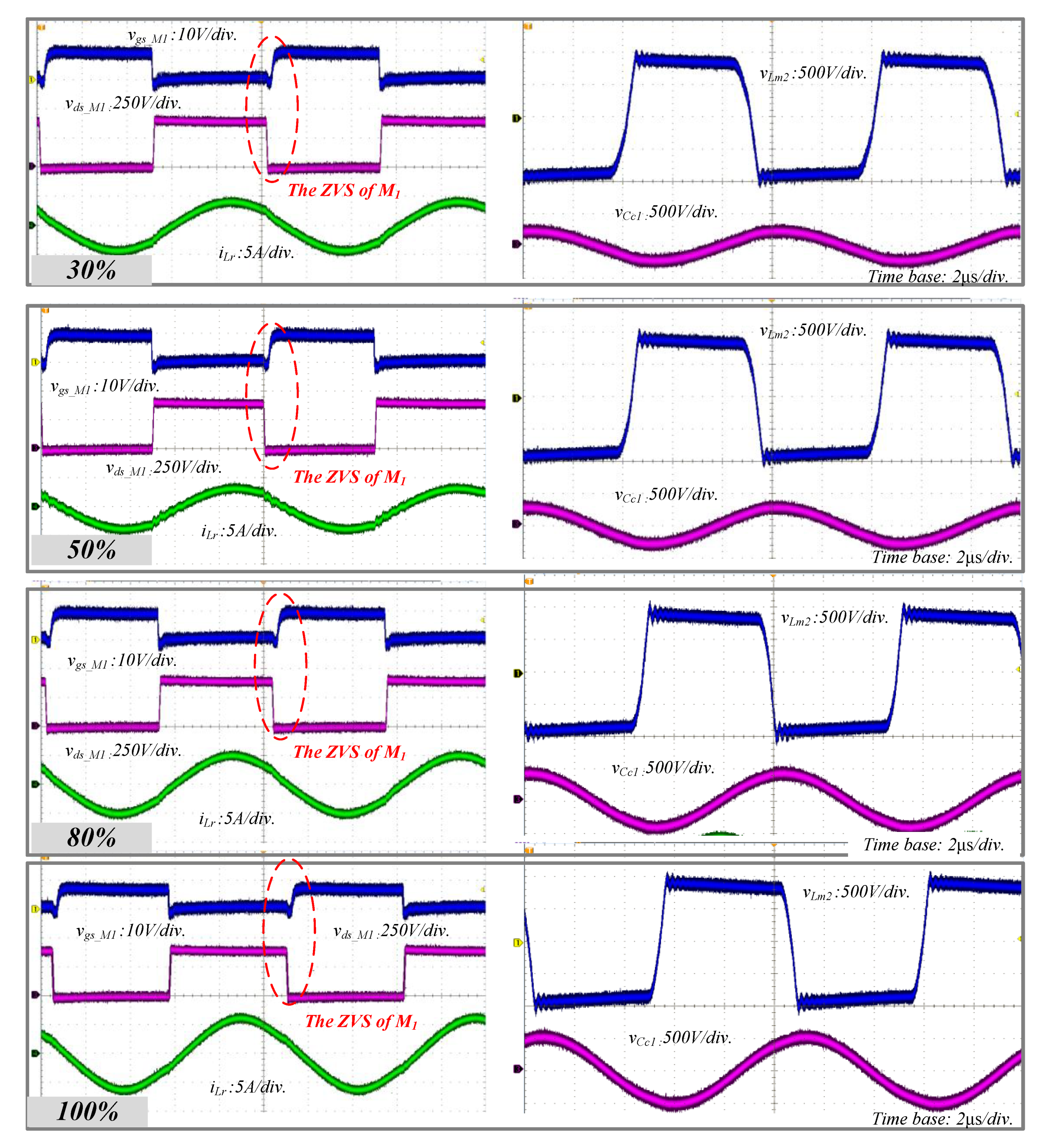
4. Experimental Results

A prototype system was implemented to verify the operation and features of the proposed CCWPT system. Figure 9 is the experimental set for the prototype system. Table 2 shows parameters of the prototype. The measured capacitance of the coupling capacitor was approximately 8 nF with a 2400 cm2 rectangular area. The electrodes are made of copper tape. Even if the electrode is made of copper and transparent electrode ITO, there was no difference in circuit operation and efficiency in previous studies [21]. The thickness of the glass dielectric layer is about 2 mm. The area of the coupling capacitor used in the experiment was set considering the area and thickness of the front and rear windows of a commercial electric vehicle. The transmitting circuit was composed of a full-bridge inverter using four switches, and the receiving circuit was composed of four diodes and a full-bridge rectifier. The maximum output power is 1.6 kW. With reference to the design considerations in Section 3, the n1 of the turn ratio of the step-up transformer was set to 0.45, and the n2 of the turn ratio of the step-down transformer was set to 2.2. When the winding ratio of the transformer is designed in this way, an output voltage of 400 V or more can be obtained even if the load changes with respect to the input voltage of 400 V. The resonant inductor was designed to be 63 μH so that the output voltage could be 400 V at a switching frequency of 90 kHz. Figure 10 shows experimental waveforms according to the load variation. The experimental waveform is consistent with the theoretical analysis. When the M1 switch is turned on, the output power is transmitted through the resonance of the coupling capacitors and the resonant inductor. Even if the load changes, it can be seen that the switch M1 is turned on after the voltage between the drain source of the switch M1 is completely discharged, and the ZVS operation is performed and the voltage of the magnetizing inductor of the step-down transformer is the output voltage, taking into account the turn ratio as shown in Figure 10. The voltage peak of a coupling capacitor made of the glass depends on the load. This confirms that the proposed CCWPT’s circuit behavior is the same as the quasi-LLC converter operation. Figure 11 shows the efficiency from DC input to DC output with load. It shows high efficiency over 95% at 1.6 kW output with the WT333E power meter. Even if the load is 30% or less, it has an efficiency of 90% or more. The proposed CCWPT system has high efficiency over the entire load. The proposed CCWPT system has a low operating frequency because two transformers can make the coupling capacitance large. Due to the low operating frequency, a typical silicon-based MOSFET can be used. The proposed system is capable of delivering large power using a window that is widely located in vehicles and has high efficiency.

5. Conclusions

A new CCWPT system is proposed for charging the EVs. The studied CCWPT uses the EVs’ glass dielectric layer for large coupling capacitance, and sufficient output power can be obtained with the two transformers such as the step-up and step-down transformers. Coupling capacitance can be estimated similar to that of a typical flat plate electrode capacitance. The glass has large relative permittivity and the EVs have large areas of glass in the front, back, and on the sides. This results in transferring large output power with a relatively large coupling capacitance, and a strong electric field can be trapped in the dielectric, which has the advantage of stability. The desired output voltage and power can be obtained, and the deviation of the coupling capacitance and the resonance inductance can be compensated by adjusting the turn ratios of the two transformers. The proposed CCWPT system employs quasi-LLC resonant power conversion circuit to reduce the switching loss of power switches. Since a turn-on loss of the power MOSFET by the ZVS in a transmitter and a turn-off loss of the rectifier the ZCS in a receiver can be decreased, high efficiency can be obtained. Because the operating frequency is not high, the proposed CCWPT system can use a low-cost existing silicon-based MOSFET. Therefore, the proposed CCWPT system is suitable for replacing the conventional ICWPT to charge EVs.

Funding

This research received no external funding.

Acknowledgments

K. Yi would particularly like to thank Y. You for his help in obtaining experimental results during this work and G. Bang for his help in editing the diagram of the paper. Y. You has worked for HS Haesung Corp. in the Republic of Korea since 2017 and G. Bang has studied for a master’s degree at Daegu Univ. since 2019.

Conflicts of Interest

The author declares no conflict of interest.

References

  1. Gjelaj, M.; Hashemi, S.; Andersen, P.B.; Træholt, C. Optimal infrastructure planning for EV fast-charging stations based on prediction of user behavior. IET Electr. Syst. Transp. 2020, 10, 1–12. [Google Scholar] [CrossRef] [Green Version]
  2. Huang, L.; Hu, A.P.; Swain, A.; Kim, S.; Ren, Y. An overview of capacitively coupled power transfer—A new contactless power transfer solution. In Proceedings of the IEEE Conference on Industrial Electronics and Applications, Melbourne, Australia, 19–21 June 2013; pp. 461–465. [Google Scholar]
  3. Zhang, H.; Lu, F. An Improved Design Methodology of the Double-Sided LC-Compensated CPT System Considering the Inductance Detuning. IEEE Trans. Power Electron. 2019, 34, 11396–11406. [Google Scholar] [CrossRef]
  4. Yi, K. High frequency capacitive coupling wireless power transfer using glass dielectric layers. In Proceedings of the 2016 IEEE Wireless Power Transfer Conference, Aveiro, Portugal, 5–6 May 2016; pp. 1–3. [Google Scholar]
  5. Dai, J.; Ludois, D.C. A survey of wireless power transfer and a critical comparison of inductive and capacitive coupling for small gap applications. IEEE Trans. Power Electron. 2015, 30, 964–969. [Google Scholar] [CrossRef]
  6. Theodoridis, M.P. Effective capacitive power transfer. IEEE Trans. Power Electron. 2012, 27, 4906–4913. [Google Scholar] [CrossRef]
  7. Nishiyama, H.; Nakamura, M. Capacitance of disk capacitors. IEEE Tran. Compon. Hybrids. Manuf. Technol. 1993, 16, 306–366. [Google Scholar] [CrossRef]
  8. Ludois, D.C.; Erickson, M.J.; Reed, J.K. Aerodynamic fluid bearing for translational and rotating capacitors in noncontact capacitive transfer systems. IEEE Trans. Ind. Appl. 2014, 50, 1025–1033. [Google Scholar] [CrossRef]
  9. Dai, J.; Ludois, D.C. Wireless electric vehicle charging via capacitive power transfer through a conformal bumper. In Proceedings of the IEEE Applied Power Electronics Conference and Exposition (APEC), Charlotte, NC, USA, 15–19 March 2015; pp. 15–19. [Google Scholar]
  10. Zhang, H.; Lu, F.; Hofmann, H.; Liu, W.; Mi, C.C. Six-plate coupler to reduce electric field emission in large air-gap capacitive power transfer. IEEE Trans. Power Electron. 2018, 33, 669–675. [Google Scholar] [CrossRef]
  11. Yusop, Y.; Husin, H.; Saat, S.; Nguang, S.; Ghani, Z. Class-E LCCL for capacitive power transfer system. In Proceedings of the IEEE 2016 Power and Energy Conference, Melaka, Malaysia, 28–30 November 2016; pp. 428–433. [Google Scholar]
  12. Narayanamoorthi, R.; Juliet, A.V.; Chokkalingam, B.; Padmanaban, S.; Leonowicz, Z.M. Class E power amplifier design and optimization for the capacitive coupled wireless power transfer system in biomedical implants. Energies 2017, 10, 1409. [Google Scholar]
  13. Mishra, S.; Adda, R.; Sekhar, S.; Joshi, A.; Rathore, A. Power transfer using portable surfaces in capacitively coupled power transfer technology. IET Power Electron. 2016, 9, 997–1008. [Google Scholar] [CrossRef]
  14. Rozario, D.; Pathipati, V.; Ram, A.; Azeez, N.; Williamson, S. Modified resonant converters for contactless capacitive power transfer system used in EV charging applications. In Proceedings of the IECON 2016—42nd Annual Conference of the IEEE Industrial Electronics Society, Florence, Italy, 23–26 October 2016; pp. 4510–4517. [Google Scholar]
  15. Choi, S.; Choi, H. Capacitive wireless power transfer system with double matching transformers for reduced stress and extended ZVS range. In Proceedings of the IECON 2016—42nd Annual Conference of the IEEE Industrial Electronics Society, Florence, Italy, 23–26 October 2016; pp. 1–6. [Google Scholar]
  16. Zhang, H.; Lu, F.; Hofmann, H.; Mi, C. A loosely coupled capacitive power transfer system with LC compensation circuit topology. In Proceedings of the IEEE Energy Conversation Congress Exposition (ECCE), Milwaukee, WI, USA, 18–22 September 2016; pp. 1–5. [Google Scholar]
  17. Lu, F.; Zhang, H.; Hofmann, H.; Mi, C. A CLLC-compensated high power and large air-gap capacitive power transfer system for electric vehicle charging applications. In Proceedings of the IEEE Applied Power Electronics Conference and Exposition, Long Beach, CA, USA, 20–24 March 2016; pp. 1721–1725. [Google Scholar]
  18. Lu, F.; Zhang, H.; Hofmann, H.; Mi, C. A double-sided LCLC-compensated capacitive power transfer system for electric vehicle charging. IEEE Trans. Power Electron. 2015, 30, 6011–6014. [Google Scholar] [CrossRef]
  19. Zhang, H.; Lu, F.; Hofmann, H.; Liu, W.; Mi, C. A four-plate compact capacitive coupler design and LCL-compensated topology for capacitive power transfer in electric vehicle charging application. IEEE Trans. Power Electron. 2016, 31, 8541–8551. [Google Scholar]
  20. Li, S.; Liu, Z.; Zhu, L.; Shuai, C.; Chen, Z. Wireless power transfer by electric field resonance and its application in dynamic charging. IEEE Trans. Ind. Electron. 2016, 63, 6602–6612. [Google Scholar] [CrossRef]
  21. You, Y.S.; Yi, K.H. Capacitive coupling wireless power transfer with glass dielectric layers for electric vehicles. In Proceedings of the IEEE 6th International Conference on Consumer Electronics-Berlin (ICCE-Berlin), Berlin, Germany, 5–7 September 2016. [Google Scholar]
  22. Yi, K. Research on Glass Dielectric Capacitive Coupling Wireless Power Transfer Using Transparent Electrode. Trans. Korean Inst. Power Electron. 2018, 23, 286–289. [Google Scholar]
  23. Frontal Vehicle Glass. Available online: https://mechaniclove.com/glass/ (accessed on 6 April 2020).
  24. Available online: https://www.researchgate.net/figure/Optical-transmittance-spectra-of-ITO-thin-films-deposited-at-different-substrate_fig4_271510410 (accessed on 3 April 2020).
  25. Kenney, J.B. Dedicated short-range communications (DSRC) standards in the United States. Proc. IEEE 2011, 99, 1162–1182. [Google Scholar] [CrossRef]
Figure 1. Electric vehicle charging method. (a) Slow wired charging. (b) Quick wired charging. (c) Wireless power transfer (WPT) charging.
Electronics 09 00676 g001
Figure 2. Coupling capacitor implementation in a vehicle.
Electronics 09 00676 g002
Figure 3. Proposed capacitive coupling wireless power transfer (CCWPT) charging system using the windows of an electric vehicle.
Electronics 09 00676 g003
Figure 4. Proposed quasi-LLC resonant CCWPT power conversion circuit.
Electronics 09 00676 g004
Figure 5. Key waveforms of the proposed CCWPT circuit.
Electronics 09 00676 g005
Figure 6. Structure of capacitor with glass dielectric layer.
Electronics 09 00676 g006
Figure 7. Equivalent circuit for the proposed CCWPT system.
Electronics 09 00676 g007
Figure 8. Output voltage gain according to the transformer turn ratios. (a) Output voltage gain according to a turn ratio of transformer T1. (b) Output voltage gain according to a turn ratio of transformer T2.
Electronics 09 00676 g008
Figure 9. Experimental set: transmitter circuit, rectifier, the resonant inductor, two transformers, the coupling capacitors using glass and copper plate.
Electronics 09 00676 g009
Figure 10. Experimental key waveforms according to load variation: the gate-source voltage of M1, the drain-source voltage of M1, the resonant inductor current, the voltage across the magnetized inductor of the transformer T2, the voltage of the coupling capacitor, the zero voltage switching (ZVS) operation of M1.
Electronics 09 00676 g010
Figure 11. Power conversion efficiency according to output power.
Electronics 09 00676 g011
Table 1. Relative permittivity of according to material in vehicle’s exterior.
MaterialRelative Permittivity
Air1.0005
Glass4–7
Polypropylene2.2–2.4
ABS Resin2.3–2.5
Table 2. Specific Components of Prototype.
ParametersSymbolValue/Part
Input voltageVin400 V
Output powerPo1.6 kW
Resonant inductorLr63 μH
n1 and n2Np1:Ns1 and Np2:Ns21:2.2 and 2.2:1
Magnetizing inductor of T2Lm21600 μH
Coupling capacitorCC1 and CC216 nF
Transformer coreT1 and T2EI6044
Primary switchesM1,2,3,4STW13NK100Z
DiodesD1,2,3,4VS-HFA16PA60C-N3
Width of glass-2 mm
Coupling capacitor electrode-Copper

