Article

Dual-Mode FPGA-Based Triple-TDC With Real-Time Calibration and a Triple Modular Redundancy Scheme

1
Department of Electronics Engineering, Chang Gung University, Taoyuan City 330, Taiwan
2
Department of Radiation Oncology, Chang Gung Memorial Hospital-LinKou, Taoyuan City 330, Taiwan
Electronics 2020, 9(4), 607; https://doi.org/10.3390/electronics9040607
Submission received: 10 March 2020 / Revised: 26 March 2020 / Accepted: 1 April 2020 / Published: 3 April 2020

Abstract

:
This paper proposes a triple time-to-digital converter (TDC) for a field-programmable gate array (FPGA) platform with dual operation modes. First, the proposed triple-TDC employs the real-time calibration circuit followed by the traditional tapped delay line architecture to improve the environmental effect for the application of multiple TDCs. Second, the triple modular redundancy scheme is used to deal with the uncertainty in the FPGA device for improving the linearity for the application of a single TDC. The proposed triple-TDC is implemented in a Xilinx Virtex-5 FPGA platform and has a time resolution of 40 ps root mean square for multi-mode operation. Moreover, the ranges of differential nonlinearity and integral nonlinearity can be improved by 56 % and 37 % , respectively, for single-mode operation.

1. Introduction

Time-to-digital converters (TDCs) are crucial components in scientific applications [1,2,3], such as positron emission tomography (PET) [4,5,6,7,8,9], time-of-flight (TOF) image sensors [9,10], and light detection and ranging (LiDAR) [11,12,13,14]. For the application of TOF-PET [7,8,9,15,16], it can determine the position accurately by measuring the time difference between the tracer within the response line, and the multi-channel TDCs are required for measuring the time difference accurately to reconstruct the images. Numerous researchers have implemented TDCs in field-programmable gate arrays (FPGAs) due to their low cost, low development time, and flexibility [17,18,19,20,21,22,23,24,25,26,27,28,29,30,31]. The time resolution and linearity are important parameters in FPGA-based TDC designs [17]; however, the process variation in the fabrication of FPGAs can lead to serious nonlinearity. Consequently, researchers have designed specific calibration circuits to deal with the issue of nonlinearity in FPGA-based TDCs.
To improve the linearity in FPGA-based TDC design, Kalisz et al. presented the calibration circuit to implement a TDC having a resolution of 200 ps and a measurement range of 43 ns in a QuickLogic pASIC FPGA device [18,19]. In reference [20], TDCs with a resolution of 65 and 46.2 ps including time calibration were implemented in an Altera FPGA device and a Xilinx FPGA device, respectively. Wang et al. used the command LOC and RLOC to specify the location of delay cells in Xilinx ISE tools [21], which enabled P&R to be performed automatically with EDA tools. Thus, the time-consuming process of manually performing P&R could be avoided. Wave-union TDCs improve the time resolution of FPGA-based TDCs, especially when ultra-wide bins (UWBs) occur in FPGA-based TDCs [22,23,24]. An averaging multiple delay line is used to smooth out large quantization errors [25] and thus improve the time resolution. However, an FPGA-based TDC with such a delay line has a complex architecture. In general, the measured integral nonlinearity (INL) and differential nonlinearity (DNL) are important metrics influencing the time linearity. Thus, several schemes have been presented to correct INL or DNL values by using time histograms [14,26,27,28,29].
In this paper, a dual-mode FPGA-based triple-TDC is proposed to deal with the environment effect and improve the time linearity. Three separated tapped delay lines (TDLs) and their corresponding calibration circuits are used in the Xilinx Virtex-5 FPGA device [28,29]. Therefore, the proposed triple-TDC improves the temperature variation effect. The measurement results indicate that the triple-TDC achieves a time resolution of the 40 ps root mean square (RMS) for multimode operation. The triple modular redundancy (TMR) scheme [32] is used to improve the uncertainty in the FPGA device for single-mode operation, such as the UWB effect. The TMR triple-TDC can achieve a resolution of 35.5 ps RMS and improve INL and DNL values by an average of 56 % and 37 % , respectively.

2. Proposed FPGA-Based Triple-TDC

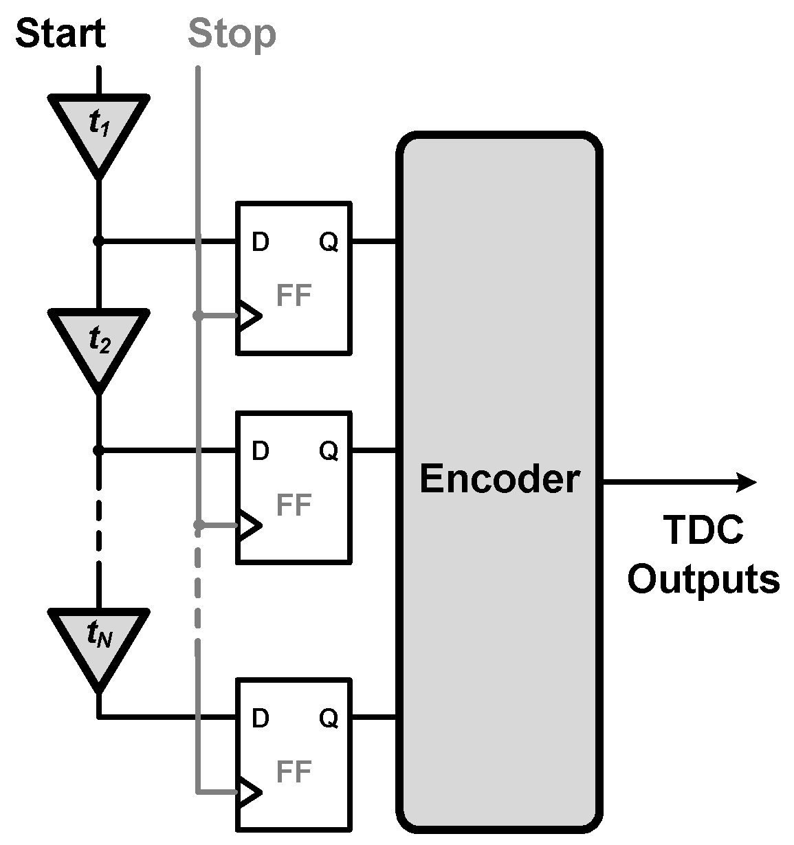
2.1. Tapped Delay Line TDC

The TDL is a popular structure for FPGA-based TDC design because it has a simple structure and is easy to design. Figure 1 illustrates the architecture of the traditional TDL-TDC, which includes N delay buffers, N registers, and an encoder module for N-bin TDC. An FPGA is a suitable platform for TDL-TDC implementation due to its regular slice structure. However, the delay buffers manufactured for FPGA-based TDCs have a nonuniform delay. Figure 2 displays the time distribution of the delay buffer for the three separated TDLs, which is measured based on the code density method. The TDLs have a nonuniform delay time due to their different delay buffers. The calibration circuit presented in reference [29] improves the uniformity in the delay time of TDLs.

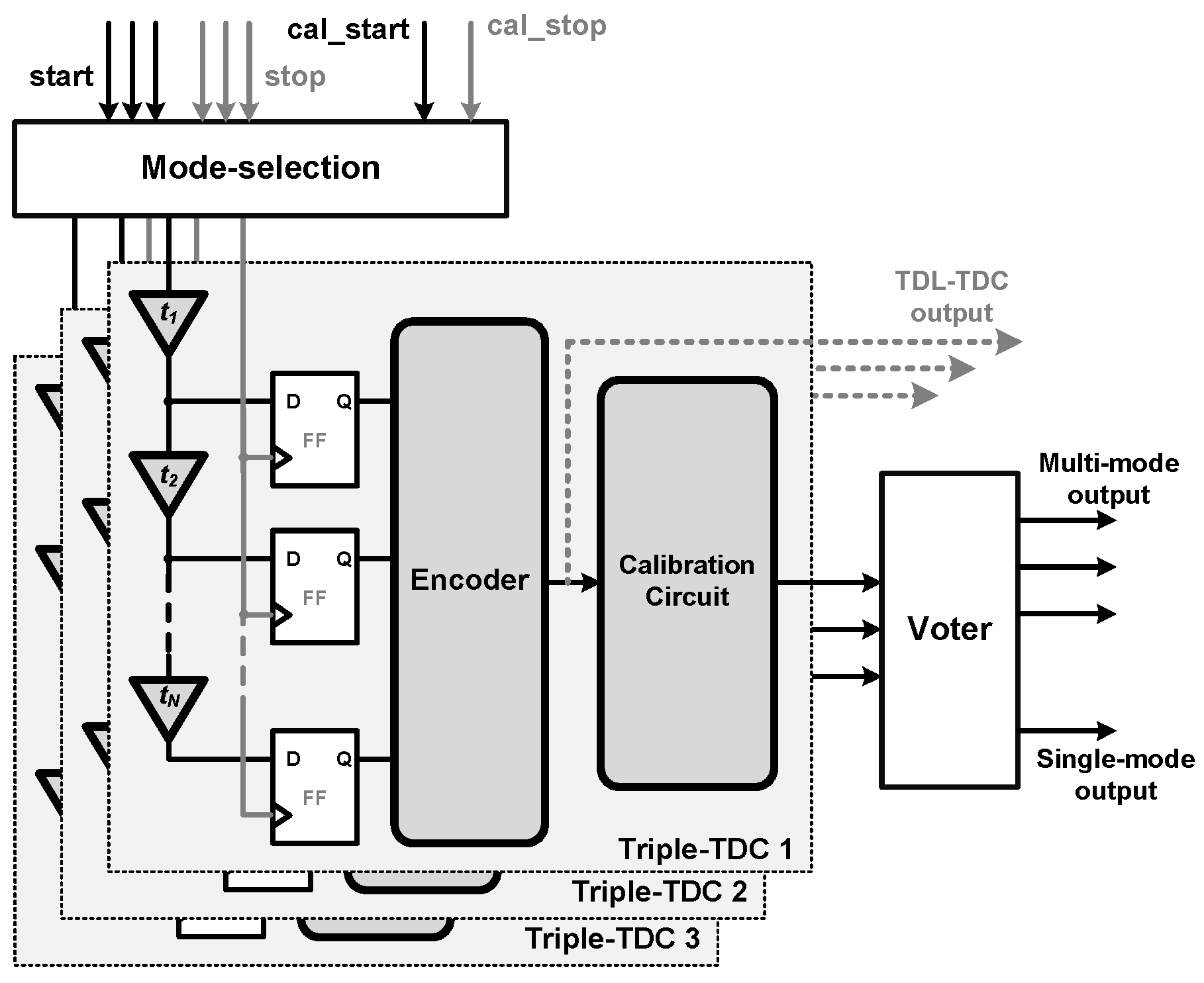
2.2. Proposed Triple-TDC Design

The proposed triple-TDC implements three separated TDLs with their corresponding calibration circuits. Figure 3 illustrates the architecture of the proposed triple-TDC, which consists of a mode-selection module, three TDLs and their corresponding calibration circuits, and a voter module. For the multiple-time conversion mode called as multi-mode, the mode-selection module passes three start and stop time signals to convert three time differences and the voter module bypasses the three digital codes. For the single-time conversion mode, a single start and stop time signal is broadcast to three TDLs, and the voter module converts a single time difference value according to the majority selection. In accordance with the concept of TMR, the proposed triple-TDC allocates three TDLs for every 20 vertical slice chains to obtain good diversity in a single FPGA chip. Figure 4 illustrates the layout of three TDLs in the Xilinx Virtex-5 FPGA chip. In comparison with the previous TDL-based TDC, the proposed triple-TDC has the following key advantages and disadvantages:
Advantages:
  • Three TDLs can be layout into different locations of a single FPGA chip, thus the diversity of the delay cell can improve the uncertainty of time delay with the TMR technology. The time resolution can be improved.
  • The proposed triple-TDC provides dual operation modes for multi-channel and high-resolution applications.
Disadvantages:
  • For the high-resolution application (single-mode), three-fold resources are used to improve the resolution. The resources overhead include area, power, and speed.

2.3. Triple-TDC Implementation

The proposed triple-TDC is implemented in a Xilinx XUPV5-LX110T ML505 FPGA evaluation board. The chip number is Xilinx XC5VLX110T-1FF1136 FPGA, and the EDA tool used is Xilinx ISE 14.7 tool. Three TDLs are allocated in the X40, X60, and X80 vertical slice chains with a high-speed carry cell called CARRY4 by using the LOC command for Xilinx ISE 14.7 tool, which is exclusively used by Xlinix FPGAs. A total of 512 delay buffers are employed for each TDL, and 128 cells are adapted after the calibration circuit, which covers the 6-ns conversion range. This is limited by the number of vertical slices and the delay time of the CARRY4 cell. Thus, the least-significant bit (LSB) value of the proposed triple-TDC is 6000 / 128 = 46.875 ps. Table 1 presents the resource usage of the proposed triple-TDC with TMR in the XC5VLX110T FPGA. A total of 4 % and 9 % of slice resources are used for slice registers and look-up tables (LUTs), respectively. A limited amount of resources are used in the proposed design. The operation flow char is shown in Figure 5. First, the calibration circuit will run the code density test to calibrate the linearity of these three TDLs. Then, the time conversion can be operated with the three-time conversion and high-resolution TMR time conversion for multi-mode and single-mode, respectively.

3. Experimental Results and Discussion

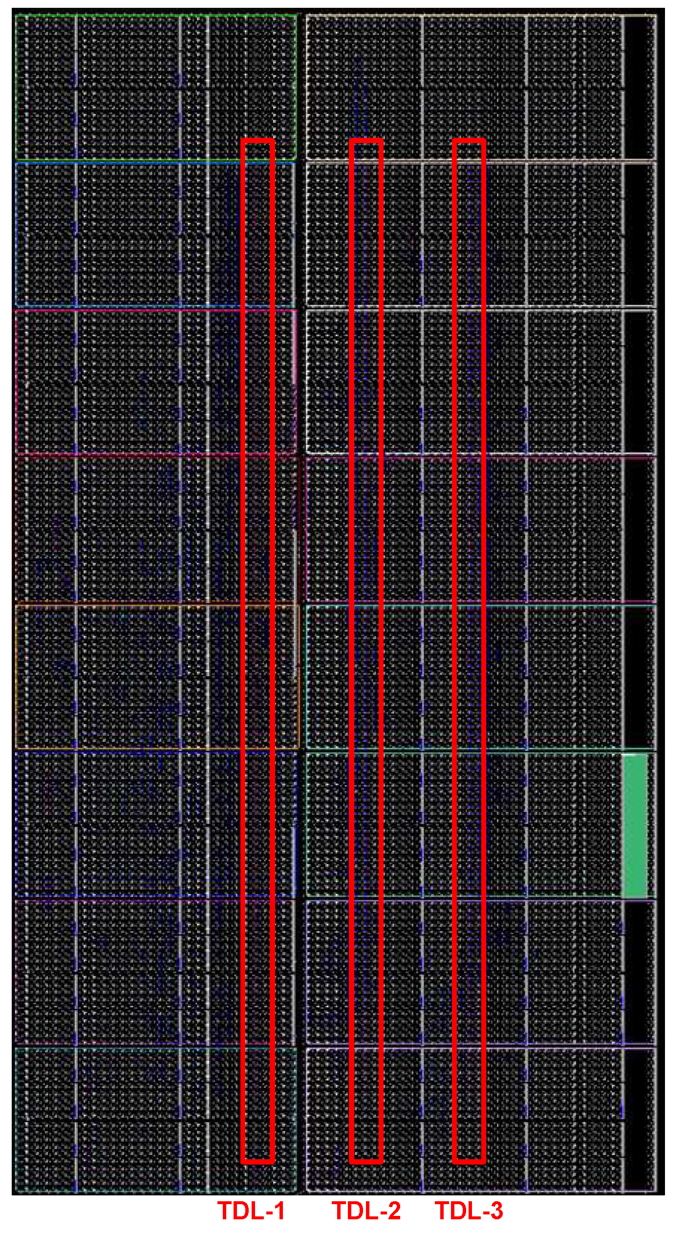
3.1. Experimental Setup

The calibration circuits employ the code density test for DNL calibration. Thus, the calibration cal_start and cal_stop signals are generated from two uncorrelated sources: (1) the on-board 100-MHz differential oscillator with an on-chip phase-locked loop (PLL) for generating the 166-MHz cal_start clock signal and (2) the on-board 200-MHz oscillator with another on-chip PLL for generating the 166-MHz cal_stop clock signal. These two uncorrelated cal_start and cal_stop signals sent to calibrate three TDL of the proposed triple-TDC. The run-time conversion start and stop signals are generated from an Agilent 81130A instrument for multi-mode operation. Moreover, a constant-delay stop signal generated from the start signal is adapted in single-mode operation to measure the RMS of the triple-TDC with the TMR function. Figure 6 illustrates the experimental setup of the measurement environment. The conversion output is connected to the host of PC, and the Xilinx ChipScope Pro and Matlab tools will capture and analyze the conversion times.

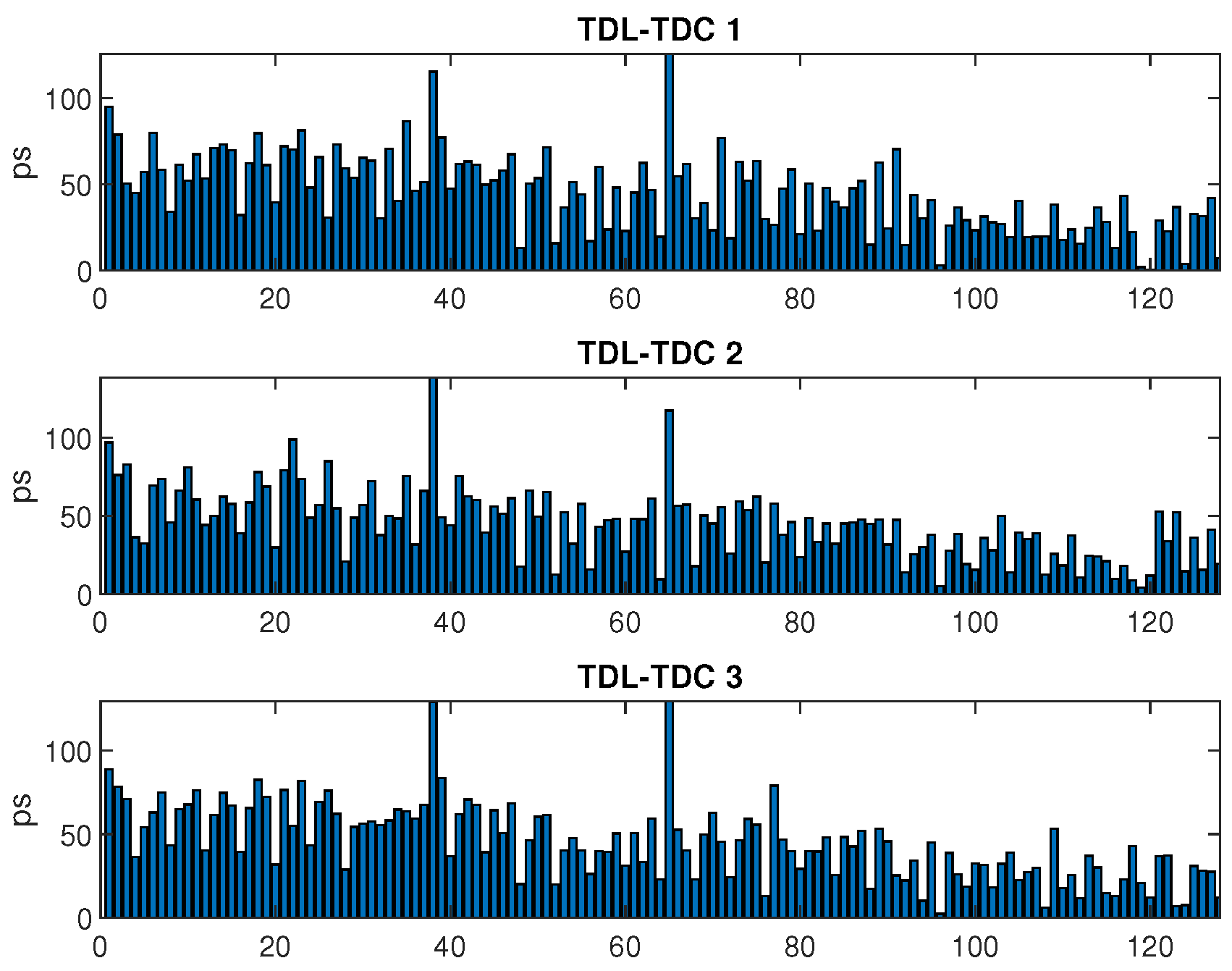
3.2. Experimental Results

To demonstrate the performance of the proposed FPGA-based triple-TDC, 2 20 tests were conducted to calculate the time linearity (DNL and INL) and time resolution (RMS). In the multi-mode operation, the proposed triple-TDC can convert three time difference signals. The measurement results indicate that the DNL values of the triple-TDC were [ 0.80 , 0.84 ] , [ 0.99 , 0.85 ] , and [ 0.92 , 0.94 ] LSBs and that the INL values were [ 7.2 , 4.3 ] , [ 7.5 , 4.2 ] , and [ 9.7 , 4.6 ] LSBs. The DNL values of the triple-TDC improved by 50 % , 49 % , and 47 % compared with the DNL values of the traditional TDL-TDC without calibration. Moreover, the INL values improved by 34 % , 28 % , and 15 % after calibration, as displayed in Figure 7 and summarized in Table 2. Note that the results of TDL-TDC without calibration are measured from the same TDLs, as shown in Figure 3. Furthermore, the time resolution of the RMS values was measured using the constant-delay input. The histogram in Figure 8 indicates that the three TDCs had good RMS values, especially the first TDC, which achieved a time resolution of 3.2 ps RMS.
In the single-mode operation, the voter module calculates the major conversion time to avoid the uncertainty effect in the FPGA chip. According to the diversity of the TDLs, the INL and DNL values can be improved. The results indicated that the DNL and INL values were [ 0.78 , 0.76 ] and [ 7.2 , 4.3 ] with the proposed TMR, respectively. As shown in Table 3, the proposed triple-TDC with TMR enhances the INL values by 37 % and 22 % and the DNL values by 56 % and 9 % compared with the traditional TDL-TDC and triple-TDC without TMR, respectively. Furthermore, a resolution of 35.5 ps RMS can be achieved with the TMR scheme, which enhances the resolution of the triple-TDC by 11.3 % compared with that of the traditional TDL-TDC. Figure 9 illustrates the INL, DNL, and RMS values for the proposed triple-TDC with TMR.

4. Conclusions

A triple-TDC is implemented in the Xilinx FPGA platform with a real-time calibration circuit. The triple-TDC utilizes the three TDCs with different calibration circuits to deal with the environmental effect for multi-mode operation and employs TMR scheme to avoid the manufacturing effect in the FPGA chip for single-mode operation. The measurement results indicate that the proposed triple-TDC can achieve DNL and INL values superior to those of the traditional TDL-TDC. The proposed triple-TDC with TMR enhances the INL values by 37 % and 22 % and the DNL values by 56 % and 9 % compared with the traditional TDL-TDC and triple-TDC without TMR, respectively. Moreover, a high RMS time resolution is achieved. Consequently, the proposed FPGA-based TDC avoids the environmental and manufacturing effects and is recommended for multi-channel applications, such as PET and TOF-PET. Furthermore, the TMR scheme improves the time resolution for high-accuracy scientific applications.

Funding

This work was supported in part by the Ministry of Science and Technology of Taiwan (MOST 108-2221-E-182-052), Chang Gung University (BMRPE26), and Chang Gung Memorial Hospital (CMRPD2G0313, CMRPD2H0301, CIRPD2F0014).

Acknowledgments

The author would like to thank the Particle Physics and Beam Delivery Core Laboratory of Institute for Radiological Research, Chang Gung University/Chang Gung Memorial Hospital, Linkou, for their assistance. The author would like to thank the Taiwan Semiconductor Research Institute (TSRI), Taiwan, for providing the circuit design automation tools.

Conflicts of Interest

The author declares no conflict of interest.

References

  1. Chen, Z.; Shi, W.; Xiong, G.; Yang, J.; Xu, Y. A 63.3ps TDC Measurement System Based on FPGA for Pulsed Laser Ranging. In Proceedings of the 2019 IEEE 13th International Conference on ASIC (ASICON), Chongqing, China, 29 October–1 November 2019; pp. 1–4. [Google Scholar]
  2. Garzetti, F.; Lusardi, N.; Geraci, A.; Dobovicnik, E.; Cautero, G.; Dri, C.; Sergo, R.; Stebel, L. Fully FPGA-based and all-reconfigurable TDC for 3D (X, Y, t) Cross Delay-Line detectors. In Proceedings of the 2018 IEEE Nuclear Science Symposium and Medical Imaging Conference Proceedings (NSS/MIC), Sydney, Australia, 10–17 November 2018; pp. 1–3. [Google Scholar]
  3. Arabul, E.; Paesani, S.; Tancock, S.; Rarity, J.; Dahnoun, N. A Precise High Count-Rate FPGA Based Multi-Channel Coincidence Counting System for Quantum Photonics Applications. IEEE Photonics J. 2020, 12, 1–14. [Google Scholar] [CrossRef]
  4. Moses, W.W.; Buckley, S.; Vu, C.; Peng, Q.; Pavlov, N.; Choong, W.; Wu, J.; Jackson, C. OpenPET: A Flexible Electronics System for Radiotracer Imaging. IEEE Trans. Nucl. Sci. 2010, 57, 2532–2537. [Google Scholar] [CrossRef] [Green Version]
  5. Sportelli, G.; Belcari, N.; Guerra, P.; Spinella, F.; Franchi, G.; Attanasi, F.; Moehrs, S.; Rosso, V.; Santos, A.; Del Guerra, A. Reprogrammable Acquisition Architecture for Dedicated Positron Emission Tomography. IEEE Trans. Nucl. Sci. 2011, 58, 695–702. [Google Scholar] [CrossRef]
  6. Yousif, A.S.; Haslett, J.W. A Fine Resolution TDC Architecture for Next Generation PET Imaging. IEEE Trans. Nucl. Sci. 2007, 54, 1574–1582. [Google Scholar] [CrossRef]
  7. Junnarkar, S.S.; O’Connor, P.; Vaska, P.; Fontaine, R. FPGA-Based Self-Calibrating Time-to-Digital Converter for Time-of-Flight Experiments. IEEE Trans. Nucl. Sci. 2009, 56, 2374–2379. [Google Scholar] [CrossRef]
  8. Marino, N.; Baronti, F.; Fanucci, L.; Saponara, S.; Roncella, R.; Bisogni, M.G.; Guerra, A.D. A Multichannel and Compact Time to Digital Converter for Time of Flight Positron Emission Tomography. IEEE Trans. Nucl. Sci. 2015, 62, 814–823. [Google Scholar] [CrossRef]
  9. Aguilar, A.; Garcia-Olcina, R.; Leiva, I.; Martinez, P.A.; Martos, J.; Soret, J.; Suarez, A.; Torres, J.; Benlloch, J.M.; Gonzalez, A. Optimization of a Time-to-Digital Converter and a coincidence map algorithm for TOF-PET applications. J. Syst. Archit. 2015, 61, 40–48. [Google Scholar] [CrossRef]
  10. Ronchini Ximenes, A.; Padmanabhan, P.; Charbon, E. Mutually Coupled Time-to-Digital Converters (TDCs) for Direct Time-of-Flight (dTOF) Image Sensors. Sensors 2018, 18, 3413. [Google Scholar] [CrossRef] [Green Version]
  11. Li, X.; Yang, B.; Xie, X.; Li, D.; Xu, L. Influence of Waveform Characteristics on LiDAR Ranging Accuracy and Precision. Sensors 2018, 18, 1156. [Google Scholar] [CrossRef] [Green Version]
  12. Zhang, C.; Lindner, S.; Antolovic, I.M.; Wolf, M.; Charbon, E. A CMOS SPAD Imager with Collision Detection and 128 Dynamically Reallocating TDCs for Single-Photon Counting and 3D Time-of-Flight Imaging. Sensors 2018, 18, 4016. [Google Scholar] [CrossRef] [Green Version]
  13. Adamo, G.; Busacca, A. Time Of Flight measurements via two LiDAR systems with SiPM and APD. In Proceedings of the 2016 AEIT International Annual Conference (AEIT), Capri, Italy, 5–7 October 2016; pp. 1–5. [Google Scholar]
  14. Chen, Y.H. Time Resolution Improvement Using Dual Delay Lines for Field-Programmable-Gate- Array-Based Time-to-Digital Converters with Real-Time Calibration. Appl. Sci. 2019, 9, 20. [Google Scholar] [CrossRef] [Green Version]
  15. Won, J.Y.; Lee, J.S. Highly Integrated FPGA-Only Signal Digitization Method Using Single-Ended Memory Interface Input Receivers for Time-of-Flight PET Detectors. IEEE Trans. Biomed. Circuits Syst. 2018, 12, 1401–1409. [Google Scholar] [CrossRef] [PubMed]
  16. Wu, B.; Wang, Y.; Cao, Q.; Kuang, J.; Wang, M.; Zhou, X. An FPGA-based Time Sampling Charge Measurement Method for TOF-PET Detectors. In Proceedings of the 2019 IEEE International Instrumentation and Measurement Technology Conference (I2MTC), Auckland, New Zealand, 20–23 May 2019; pp. 1–5. [Google Scholar]
  17. Wu, J. Several Key Issues on Implementing Delay Line Based TDCs Using FPGAs. IEEE Trans. Nucl. Sci. 2010, 57, 1543–1548. [Google Scholar] [CrossRef]
  18. Kalisz, J.; Szplet, R.; Pasierbinski, J.; Poniecki, A. Field-programmable-gate-array-based time-to-digital converter with 200-ps resolution. IEEE Trans. Instrum. Meas. 1997, 46, 51–55. [Google Scholar] [CrossRef]
  19. Kalisz, J.; Szplet, R.; Pelka, R.; Poniecki, A. Single-chip interpolating time counter with 200-ps resolution and 43-s range. IEEE Trans. Instrum. Meas. 1997, 46, 851–856. [Google Scholar] [CrossRef]
  20. Song, J.; An, Q.; Liu, S. A high-resolution time-to-digital converter implemented in field-programmable-gate-arrays. IEEE Trans. Nucl. Sci. 2006, 53, 236–241. [Google Scholar] [CrossRef]
  21. Wang, J.; Liu, S.; Shen, Q.; Li, H.; An, Q. A Fully Fledged TDC Implemented in Field-Programmable Gate Arrays. IEEE Trans. Nucl. Sci. 2010, 57, 446–450. [Google Scholar] [CrossRef]
  22. Wu, J.; Shi, Z. The 10-ps wave union TDC: Improving FPGA TDC resolution beyond its cell delay. In Proceedings of the 2008 IEEE Nuclear Science Symposium Conference Record, Dresden, Germany, 19–25 October 2008; pp. 3440–3446. [Google Scholar]
  23. Wang, J.; Liu, S.; Zhao, L.; Hu, X.; An, Q. The 10-ps Multitime Measurements Averaging TDC Implemented in an FPGA. IEEE Trans. Nucl. Sci. 2011, 58, 2011–2018. [Google Scholar] [CrossRef]
  24. Bayer, E.; Traxler, M. A High-Resolution (<10 ps RMS) 48-Channel Time-to-Digital Converter (TDC) Implemented in a Field Programmable Gate Array (FPGA). IEEE Trans. Nucl. Sci. 2011, 58, 1547–1552. [Google Scholar]
  25. Chen, P.; Hsiao, Y.Y.; Chung, Y.S.; Tsai, W.X.; Lin, J.M. A 2.5-ps Bin Size and 6.7-ps Resolution FPGA Time-to-Digital Converter Based on Delay Wrapping and Averaging. IEEE Trans. VLSI Syst. 2017, 25, 114–124. [Google Scholar] [CrossRef]
  26. Chen, H.; Zhang, Y.; Li, D.D.U. A Low Nonlinearity, Missing-Code Free Time-to-Digital Converter Based on 28-nm FPGAs With Embedded Bin-Width Calibrations. IEEE Trans. Instrum. Meas. 2017, 66, 1912–1921. [Google Scholar] [CrossRef] [Green Version]
  27. Chaberski, D.; Zielinski, M.; Grzelak, S. The new method of calculation sum and difference histogram for quantized data. Measurement 2009, 42, 1388–1394. [Google Scholar] [CrossRef]
  28. Chen, Y.H. A counting-weighted calibration method for a field-programmable-gate-array-based time-to-digital converter. Nucl. Instrum. Methods Phys. Res. Sect. A Accel. Spectrom. Detect. Assoc. Equip. 2017, 854, 61–63. [Google Scholar] [CrossRef]
  29. Chen, Y.H. Run-time calibration scheme for the implementation of a robust field-programmable gate array–based time-to-digital converter. Int. J. Circ. Theor. Appl. 2018, 47, 19–31. [Google Scholar] [CrossRef] [Green Version]
  30. Dinh, V.L.; Nguyen, X.T.; Lee, H. A New FPGA Implementation of a Time-to-Digital Converter Supporting Run-Time Estimation of Operating Condition Variation. In Proceedings of the 2018 IEEE International Symposium on Circuits and Systems (ISCAS), Florence, Italy, 27–30 May 2018; pp. 1–4. [Google Scholar]
  31. Chen, P.; Lan, J.; Wang, R.; My Qui, N.; Marquez, J.C.J.S.; Kajihara, S.; Miyake, Y. High-Precision PLL Delay Matrix With Overclocking and Double Data Rate for Accurate FPGA Time-to-Digital Converters. IEEE Trans. VLSI Syst. 2020, 28, 904–913. [Google Scholar] [CrossRef]
  32. Chen, Y.H.; Lu, C.W.; Shyu, S.S.; Lee, C.L.; Ou, T.C. A Multi-stage Fault-tolerant Multiplier with Triple Module Redundancy (TMR) Technique. J. Circuits Syst. Comput. 2013, 23, 1450074. [Google Scholar] [CrossRef]
Figure 1. Architecture of the traditional TDL-TDC.
Electronics 09 00607 g001
Figure 2. Time distribution for three TDL-TDCs.
Electronics 09 00607 g002
Figure 3. Architecture of the proposed triple-TDC.
Electronics 09 00607 g003
Figure 4. Layout of the three TDLs in the FPGA chip.
Electronics 09 00607 g004
Figure 5. Operation flow of the proposed triple-TDC.
Electronics 09 00607 g005
Figure 6. Measurement environment of this work.
Electronics 09 00607 g006
Figure 7. Measured DNL and INL values for the triple-TDC and TDL-TDC.
Electronics 09 00607 g007
Figure 8. Measured RMS values for the proposed triple-TDC.
Electronics 09 00607 g008
Figure 9. Measured INL, DNL, and RMS values for the proposed triple-TDC with TMR.
Electronics 09 00607 g009
Table 1. Resource usage for FPGA implementation.
XC5VLX110TResourcesTriple-TDC
UsagePercentage (%)
Slice Registers69,12033014%
Slice LUTs69,12063919%
PLL_ADVs6233%
Table 2. INL and DNL for the proposed triple-TDC with multi-mode.
MethodsDNL(LSB)INL(LSB)
TDC-1w/o Cal. [−0.99, 1.68]100%[−10.9, 6.1]100%
w/i Cal. [−0.80, 0.84]50%[−7.2, 4.3]66%
TDC-2w/o Cal.[−0.92, 1.96]100%[−10.4, 6.0]100%
w/i Cal.[−0.99, 0.85]51%[−7.5, 4.2]72%
TDC-3w/o Cal.[−0.95, 1.77]100%[−11.4, 6.3]100%
w/i Cal.[−0.92, 0.94]53%[−9.7, 4.6]66%
: The traditional TDL-TDC. : The proposed TDC with time calibration.
Table 3. INL and DNL for the proposed triple-TDC with TMR in single-mode.
MethodsDNL(LSB)INL(LSB)
Traditional TDL-TDC[−0.95, 1.77]100%[−11.4, 6.3]100%
Proposed triple-TDC with Calibration[−0.92, 0.94]53%[−9.7, 4.6]85%
Proposed triple-TDC with TMR[−0.78, 0.76]44%[−7.2, 4.3]63%

