Article

Deceptive Targets Generation Simulation Against Multichannel SAR

State Key Laboratory of complex Electromagnetic Environment Effects on Electronics and Information system, National University of Defense Technology, Changsha 410073, China
*
Author to whom correspondence should be addressed.
Electronics 2020, 9(4), 597; https://doi.org/10.3390/electronics9040597
Submission received: 2 March 2020 / Revised: 24 March 2020 / Accepted: 28 March 2020 / Published: 31 March 2020
(This article belongs to the Section Microwave and Wireless Communications)

Abstract

:
Traditional synthetic aperture radar (SAR) deceptive jamming can effectively generate deceptive scenes or false targets in SAR images. However, these false targets or scenes can be easily distinguished or eliminated by the multichannel SAR system. To interfere with the multichannel SAR, we first analyzed the results of SAR deceptive jamming generated by one transponder and two transponders against three-channel SAR- ground moving target indication (GMTI). Then, we propose a new deceptive jamming method against three-channel SAR-GMTI by using three synergetic transponders. By modulating each transponder with a complex coefficient, three synergetic transponders can generate false moving targets with the controllable radial velocity and located azimuth position in three-channel SAR-GMTI. Besides, in this paper, we also introduce an algorithm to deploy three transponders reasonably by utilizing the minimum condition number. In the end, a general architecture of multiple transponders deceiving multichannel SAR is given. The proposed method can not only generate deceptive false targets against multichannel SAR-GMTI, but also guide the production of a deceptive digital elevation model (DEM) against multichannel interferometric SAR (InSAR). Simulations verify the effectiveness of the proposed method.

1. Introduction

Synthetic aperture radar (SAR) is a microwave imaging radar, offering high-resolution images sustainably, regardless of the time and the weather [1]. Thus, it is a good supplement to light imaging, widely used in civilization and military fields. Especially the usage in military, such as searching for intelligence information and carrying out battlefield surveillance, are huge threats to national security [2]. Since the first SAR image was acquired, many advanced SAR working modes have been developed. For example, the interferometric SAR (InSAR), employs two or more receiving channels to retrieve the terrain digital elevation model (DEM) of the ground surface [3,4]. In addition, SAR- ground moving target indication (SAR-GMTI), another SAR working mode, also utilizes two or more receiving channels to detect and image the moving targets by canceling the clutter and stationary targets [5]. Both InSAR and SAR-GMTI are working with multiple receiving channels, which not only help to obtain extra information but also make the jamming against them more difficult than SAR [6]. Therefore, in order to prevent multichannel SAR from observing and detecting important targets and facilities, correspondingly, the jamming method should follow up in time [7,8,9,10].
Generally, the SAR interfering techniques can be divided into barrage jamming and deceptive jamming [11,12]. The barrage jamming prevents proper imaging by covering the real targets’ signals with strong noise, which is easy to be implemented, but also requires strong power [13]. What’s worse, the barrage jamming signals could be suppressed easily because its features are different to those of the real SAR echoes. However, deceptive jamming has drawn more attention in the SAR electronic war (EW) because of its low power requirement and high hiding ability, which can confuse target recognition without arousing the awareness of enemy [14].
So far, there are many papers dealing with the deceptive jamming techniques against SAR. They primarily concentrate on transponder’s theoretical model, fast implementation algorithm [15,16,17,18,19]. However, these deceptive jamming are usually created by a single transponder. When they are utilized against InSAR or SAR-GMTI, the jamming effect would be reduced, because the created false scene or targets can be eliminated or detected by two or more receiving channels cancellation processing [20,21,22]. In [21,23], the phase difference of the jamming signals generated by a single transponder in the image domain between the master antenna and the slave antenna for InSAR was analyzed, and with the phase compensation, the jamming was easily removed. In [24], the authors concluded that all false stationary and moving targets generated by a single transponder were relocated at the same azimuth position as the transponder, which were easily identified as false targets in SAR-GMTI image. Therefore, the previously mentioned jamming generated by a single transponder plays a limit role in combating the multichannel SAR, which is due to the number of transponders less than the number of SAR receiving channels.
To solve the aforementioned problem, some researchers employed two synergetic transponders to interfere dual-channel InSAR and SAR-GMTI system [25,26,27,28,29]. In [26,27], two synergetic transponders were used to generate a false three-dimension (3D) scene in InSAR image by modulating each transponder with complex modulation coefficients. Besides, in [28,29], a new method utilizing two synergetic transponders against dual-channel SAR-GMTI was proposed, which could generate false moving targets with high fidelity. These methods are effective in jamming dual-channel SAR, but unable to work in jamming multichannel SAR. This is because the freedom of SAR receiving channels is larger than that of the combination of transponders. To improve the jamming ability against multichannel SAR, the number of transponders should be added until no less than the number of SAR receiving channels. Without loss of generality, we only consider the jamming method for SAR-GMTI system in this paper. The jamming method for InSAR is the same. In the SAR-GMTI system, the displaced phase center antenna (DPCA) technique is utilized to detect moving targets, while the along-track interferometry (ATI) technique is used to estimate their velocities and correct their positions [30,31].
Inspired by the idea that two synergetic transponders can generate effective deceptive jamming against a dual-channel SAR system, we propose a new deceptive jamming method based on multiple transponders against multichannel SAR system. In this method, each transponder is modulated with complex modulation coefficients when generating the jamming signals. The synthetic jamming signals can resist multichannel DPCA cancellation processing. As long as the number of transponders is more than the number of SAR channels, this proposed method is efficient. More specifically, the major contributions of this paper can be summarized as follows:
  • Point out that to generate false targets and scenes against multichannel SAR, the number of transponders must be more than that of SAR receiving channels.
  • Propose a new jamming method for jointly employing three transponders against three-channel SAR-GMTI.
  • Give a general scheme of multiple transponders interfering multichannel SAR, which is applicable to multichannel InSAR and SAR-GMTI systems.
  • Introduce a numerical optimization algorithm utilizing the minimum condition number to deploy multiple transponders excellently.
  • Carry out comparative experiments on the jamming performance against three-channel SAR-GMTI between using three transponders and using a single transponder or two transponders.
The rest of the paper is organized as follows. In Section 2, we analyze the performance of a single transponder against dual-channel SAR-GMTI. Then, in Section 3, we introduce an effective jamming method for utilizing two transponders against dual-channel SAR-GMTI and analyze the reason that two transponders fail to deceive three-channel SAR-GMTI. Section 4 presents a new method for using three transponders jam the three-channel SAR-GMTI system and gives a numerical optimization algorithm about the layout of multiple transponders. In Section 5, the scheme of multiple transponders against multichannel SAR is given. Simulations are presented in Section 6. Section 7 concludes this paper.

2. Analysis of a Single Transponder Against Dual-Channel SAR-GMTI Processing

2.1. A Real Moving Target

As shown in Figure 1, SAR-GMTI works at the broad-side mode with three receiving channels, which is mounted on an airplane moving at a constant velocity V a parallel to the positive X-axis direction at an altitude of H . The distance between two neighboring channels is d , satisfying DCPA condition, namely d = 2 l V a T . T is the pulse repetition period and l is a positive integer. Points A 1 , A 2 and A 3 denote three receiving channels, respectively, and their coordinates are shown by ( V a t a d , 0 , H ) , ( V a t a , 0 , H ) and ( V a t a + d , 0 , H ) varying with slow time t a , respectively. The middle channel A 2 serves as the transmitter, and all channels receive the echoes simultaneously. At time t a = 0 , a moving target p is placed at ( x p , y p , 0 ) with a constant cross-track velocity v r .
R p n ( t a ) denotes the instantaneous slant-range from the receiving channel A n to the moving target p as described in Figure 1, where n ( 1 , 2 , 3 ) serves as the index for each receiving channel and thus, R p n ( t a ) can be written as:
R p n ( t a ) = ( x p V a t a ( n 2 ) d ) 2 + ( y P + v r t a ) 2 + H 2 R p x p V a y p v r R p t a + V a 2 2 R p t a 2 + ( n 2 ) 2 d 2 2 ( n 2 ) d x p 2 R p + V a ( n 2 ) d R p t a
where R p = y p 2 + H 2 denotes the shortest distance between the moving target p and the flying track.
As is well known, SAR usually transmits linear frequency-modulation (LFM) signal to acquire high range resolution. Thus, SAR transmitting signal can be expressed as
s t ( t r , t a ) = w r ( t r T p ) exp ( j π ( 2 f 0 t r + K t r 2 ) )
where w r ( · ) is the range window function, t r is the fast time, T P is the pulse width, K denotes the frequency modulation slope, and f 0 denotes the carrier frequency.
Correspondingly, after in-phase/quadrature (I/Q) demodulation, the receiving echo from the moving target p for the channel A n can be described as
s p n ( t r , t a ) = σ ( x p , y p ) w r ( t r r p n ( t a ) / c T p ) w a ( t a x p / V a T L ) exp ( j π K ( t r r p n ( t a ) c ) 2 ) exp ( j 2 π r p n ( t a ) λ )
With
r p n ( t a ) = R p n ( t a ) + R p 2 ( t a )
where w a ( · ) is the azimuth window function, T L is the synthetic aperture time, λ is the transmitting signal wavelength, c is the speed of light, and σ ( x p , y p ) is the back-scattering coefficient of the moving target p .
Then, after range doppler (RD) image processing and co-registration, the imaging output of the channel A n can be expressed as
I n ( t r , t a ) = U sin c [ B ( t r 2 R p c ) ] sin c [ B a ( t a x p V a + v r R p V a 2 ) ] exp [ j 2 π ( n 2 ) d v r λ V a ]
where U is the complex amplitude of the target p in the image domain, B is the bandwidth of radar signal, and B a is the Doppler bandwidth.

2.2. A False Target Generated by a Single Transponder

Suppose only one transponder J 3 located at ( x j 3 , y j , 0 ) is utilized to generate false target like p , and the transponder can be considered as a stationary point. Thus, the instantaneous slant-range R j 3 n ( t a ) from the transponder J 3 to the channel A n can be written as
R j 3 n ( t a ) = ( x j 3 V a t a ( n 2 ) d ) 2 + y j 3 2 + H 2 R J x j 3 V a R J t a + V a 2 2 R J t a 2 + ( n 2 ) 2 d 2 2 ( n 2 ) d x j 3 2 R J + V a ( n 2 ) d R J t a
where R J = y j 2 + H 2 denotes the shortest distance between the moving target p and the flying track.
Considering a dual-channel SAR-GMTI system, supposing n = 2, 3, then the channel A n receiving jamming signals can be written as
s j 3 n ( t r , t a ) = σ ( x j 3 , y j ) w r ( t r r j 3 n ( t a ) / c T p ) w a ( t a x j 3 / V a T L ) exp ( j π K ( t r r j 3 n ( t a ) c ) 2 ) exp ( j 2 π r j 3 n ( t a ) λ )
with
r j 3 n ( t a ) = R j 3 n ( t a ) + R j 32 ( t a )
where σ ( x j 3 , y j ) is the amplitude modulation coefficient of the false target p .
To obtain the jamming signals of the false moving target p , the intercepted SAR signal has to be with a time-delay and a doppler modulation relative to Δ R , which is the difference of the propagation distance from the transponder and the false target to the receiving channel. Then, Δ R ( t a ) can be calculated by
Δ R ( t a ) = 2 ( R p 2 ( t a ) R j 32 ( t a ) )
Substituting Equations (4) and (8) into (9), considering R p R J , V a v r , Δ R ( t a ) can approximate as
Δ R ( t a ) = 2 R J 2 R p + 2 ( x j 3 x p ) R p V a t a + 2 y p v r R p t a
Thus, the range history of the deceptive jamming signal for the receiving channel A n can be described as
r j 3 n ( t a ) = R j 3 n ( t a ) + R j 32 ( t a ) + Δ R
Correspondingly, the jamming signals that channel A n receive can be expressed as
s j 3 n ( t r , t a ) = σ ( x j 3 , y j ) w r ( t r r j 3 n ( t a ) / c T p ) w a ( t a x j 3 / V a T L ) × exp ( j π K ( t r r j 3 n ( t a ) c ) 2 ) exp ( j 2 π r j 3 n ( t a ) λ )
Then, carrying out RD imaging for the jamming signals, and after image co-registration, the imaging output for channel A n can be written as
I j 3 n ( t r , t a ) = U 3 n G exp [ j 2 π ( n 2 ) d v r λ V a ] exp [ j 2 π ( n 2 ) d ( x p x j 3 ) R J ]
G = sin c [ B ( t r 2 R p c ) ] sin c [ B a ( t a x p V a + v r R p V a 2 ) ]
where U 3 n denote the complex amplitude of the false target p generated by transponder J 3 in SAR image of channel A n and G is the envelop function of the imaging result of the false target p .
Based on the ATI technique, the phase difference ϕ ^ between two co-registration images at the moving target position can be estimated as
ϕ ^ = arg ( I j 32 I j 33 ) = 2 π d v r λ V a + 2 π d ( x p x j 3 ) R J
Correspondingly, according to the estimated phase difference ϕ ^ , the velocity v ^ r can be estimated as
v ^ r = λ V a 2 π d ϕ ^ = v r x p x j 3 R J V a
Once the moving target has a velocity component in range direction, the position of the moving target will shift along the azimuth direction. Therefore, according to the estimated velocity, the azimuth position of false moving target p can be relocated at
x = x ^ p + R J v ^ r V a = x p R p v r V a + R J v r V a x p + x j 3 = x j 3
where x ^ p x p R p v r V a is the detected azimuth position of the deceptive target.
Apparently, the false moving target p is relocated at the same azimuth position as the transponder, thus it can be distinguished easily. According to (16), we also know, when the false target is stationary, if its azimuth is not the same as or near the transponder, it would be detected as a moving target instead of being eliminated by DPCA operation. Therefore, the false stationary target can also be relocated the same azimuth position as the transponder and also be easily identified. Therefore, the deceptive jamming generated by a single transponder plays a limit role against dual-channel SAR-GMTI.

3. Synergetic Jamming with Two Transponders

In this section, first, we introduce the principle of the existing effective jamming method based on two synergetic transponders against dual-channel SAR-GMTI. Then, we analyze the shortcomings of the two transponders jamming three-channel SAR-GMTI. In the end, we conclude that to generate false targets against multichannel SAR- GMTI, the number of transponders must be greater than the number of SAR channels.

3.1. The Effectiveness of two Transponders Against Dual-Channel SAR-GMTI

As mentioned before, the deceptive jamming method using only one transponder has a limited effect when it is utilized to jam the dual-channel SAR-GMTI. In order to explore the further reason that the jamming is invalid against dual-channel SAR-GMTI, we can make a comparison between Equations (5) and (13). It is clear that if n = 2, the two equations are absolutely the same, and namely the false target seems real in the SAR image of channel A 2 . However, for the channel A 3 , Equation (13) is attached with an additional phase term related to the azimuth distance from the transponder to the false targets. It is the additional phase that makes the false target unlike a real one. Therefore, to obtain the false targets with high fidelity, the additional phase term should be removed. A single transponder is difficult to remove the additional phase, and the phase can be easily eliminated by using two synergetic transponders.
Considering the range from the transponder to radar sensors make no difference in the additional phase of imaging output of the jamming signals, thus we add another transponder J 2 located at ( x j 2 , y j , 0 ) with the same ground range coordinate y j as J 3 . Then, the imaging output of the jamming signals generated by transponder J 2 can be written as
I j 2 n ( t r , t a ) = U 2 n G exp [ j 2 π ( n 2 ) d v r λ V a ] exp [ j 2 π ( n 2 ) d ( x p x j 2 ) R J ]
where U 2 n denote the complex amplitude of the false target p generated by transponder J 2 in SAR image of channel A n . Supposing the two transponders are completely the same, then the final amplitude of the false target U 1 n and U 2 n can be seen as the same too and. Without of loss generality, we assume it as U 0 . If the signal intercepted by two transponders is modulated with a complex modulation coefficient, then the imaging output of the composite jamming signals for channel A n can be described as
I n ( t r , t a ) = I j 2 n ( t r , t a ) + I j 3 n ( t r , t a ) = U 0 G exp [ j 2 π ( n 2 ) d v r λ V a ] g n ( Q m )
with
g n ( Q m ) = m = 2 , 3 Q m exp [ j 2 π ( n 2 ) d ( x p x j m ) R j ]
where m serves as the index for each transponder and Q m represents the complex modulation coefficient modulated in the transponder J m .
Then, if Equation (20) is equal to a constant for n = 2 , 3 , the additional phase in the channel A 3 can be ignored. For simplification, we assume the constant as 1. Then, the equation can be written as
{ Q 2 + Q 3 = 1 Q 2 exp ( j 2 π d ( x p x j 2 ) R J ) + Q 3 exp ( j 2 π d ( x p x j 3 ) R J ) = 1
Rewrite it in matrix as A Q = b
[ 1 1 a 21 a 22 ] [ Q 0 Q 1 ] = [ 1 1 ]
where a 21 = exp ( j 2 π d λ R J ( x p x j 2 ) ) , a 22 = exp ( j 2 π d λ R J ( x p x j 3 ) ) .
Solving the Equation (22), the two complex modulation coefficients can be calculated. Then applying them in two transponders separately, a desired false moving target can be generated.
Based on the DPCA technique, using I 2 ( t r , t a ) subtract I 3 ( t r , t a ) shown in Equation (19), the subtracted image I 23 can be expressed as
I 23 = I 2 ( t r , t a ) I 3 ( t r , t a ) = U 0 G exp ( j π d v r λ V a ) ( 2 j ) sin ( π d v r λ V a )
According to Equation (23), if v r = 0 , then I 23 = 0 , namely the stationary targets can be eliminated like the clutter. However, for the false moving targets, the phase difference ϕ ^ becomes
ϕ ^ = arg ( I 2 I 3 ) = 2 π d v r λ V a
Correspondingly, the estimated velocity v ^ r becomes
v ^ r = λ V a 2 π d ϕ ^ = v r
Then, the azimuth position of the false moving targets can be relocated at x p , which is the same as the setting value. Therefore, whether the false targets are moving or stationary, they can all satisfy the characteristic of the real targets. Therefore, synergetic jamming with two transponders against dual-channel SAR-GMTI is effective.

3.2. The Limitaion of Two Transponders Against Three-Channel SAR-GMTI

As stated in Section 3.1, two transponders can jam dual-channel SAR-GMTI. However, in most cases, SAR-GMTI is implemented with three receiving channels as illustrated in Figure 1. When the SAR works at three-channel mode, if continuing using two transponders, the jamming effect would be reduced.
Considering Equation (20), if the jamming is effective, it must satisfy a constant too for n = 1 . Thus, the matrix A Q = b becomes
[ 1 1 a 21 a 22 a 31 a 32 ] [ Q 1 Q 2 ] = [ 1 1 1 ]
where a 31 = exp ( j 2 π d λ R J ( x p x j 2 ) ) , a 32 = exp ( j 2 π d λ R J ( x p x j 3 ) ) . It is obvious that r a n k ( A ) r a n k ( A | b ) , thus, there is no solution of Equation (26). That’s to say, no complex coefficients can be modulated in two transponders to create false targets against three-channel SAR-GMTI. Therefore, using two transponders to generate deceptive jamming against three-channel SAR-GMTI has a limited effect.

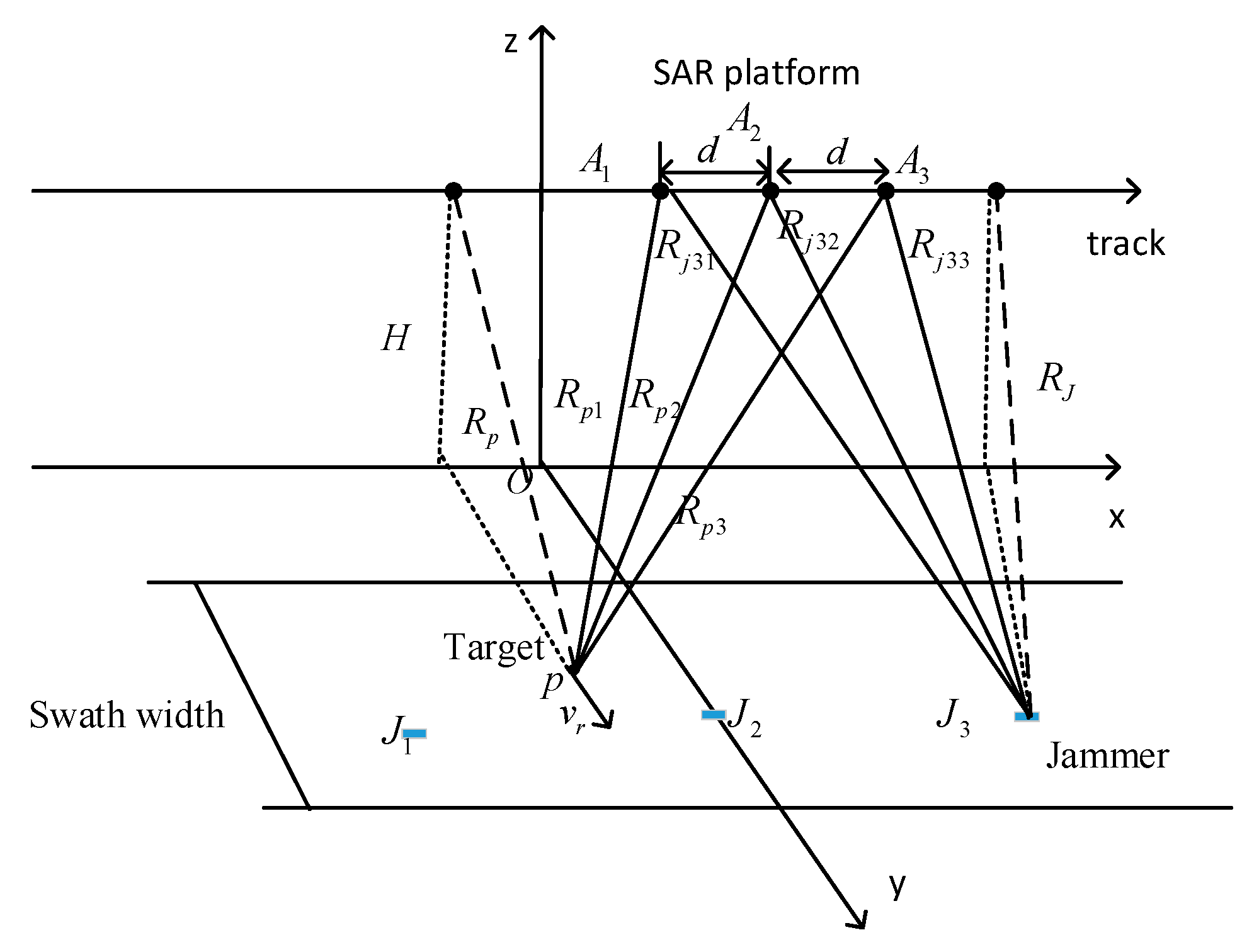
4. Synergetic Jamming with Three Transponders

The limitation of two transponders against three-channel SAR-GMTI has been analyzed above, which is because the phase terms of the synthetic jamming signals generated by two transponders for channel A 1 does not match the real target. Essentially, it is what we analyzed that the freedom of SAR receiving channels is larger than that of the combination of transponders. To generate false targets against three-channel SAR-GMTI, the number of transponders should not be less than three. Therefore, we propose a new deceptive jamming method against three-channel SAR-GMTI based on three synergetic transponders. Moreover, we also give a numerical optimization algorithm for the optimal layout of multiple transponders by utilizing the minimum condition number.

4.1. The Effectiveness of Three Transponders Against Three-Channel SAR-GMTI

Assume that three transponders J 1 , J 2 and J 3 as shown in Figure 1 are used to generate jamming signals simultaneously, where J 1 is placed at ( x j 1 , y j , 0 ) with the same ground range coordinate y j as J 2 and J 3 . Same as the previous analysis, then, the Equation (21) can be rewritten as
[ 1 a 21 a 31 1 a 22 a 32 1 a 23 a 33 ] [ Q 1 Q 2 Q 3 ] = [ 1 1 1 ]
where a 23 = exp ( j 2 π d λ R J ( x p x j 1 ) ) , a 33 = exp ( j 2 π d λ R J ( x p x j 1 ) ) . Apparently, Equation (27) has a solution
Q = A 1 b
Then, by applying the complex modulation coefficients in three transponders, the difference between the two co-registrated images for channel A 2 and A 3 is shown by Equation (23), and for channel A 1 and A 2 can be expressed as
I 12 = I 2 ( t r , t a ) I 3 ( t r , t a ) = U 0 G exp ( j π d v r λ V a ) ( 2 j ) sin ( π d v r λ V a )
According to Equation (29), we know, for the false stationery targets v r = 0 , I 12 = 0 , and namely, they are all eliminated as clutter by DPCA operation. Therefore, the false stationary targets can’t be detected by channel A 1 and A 2 DPCA operation. Accordingly, the phase difference of moving targets in two subtracted images I 12 and I 23 can be expressed as
ϕ ^ = arg ( I 12 I 23 ) = 2 π d v r λ V a
Obviously, the phase difference of the false moving target matches the setting target radial velocity. Moreover, after relocation, these false moving targets would go back to its real position.

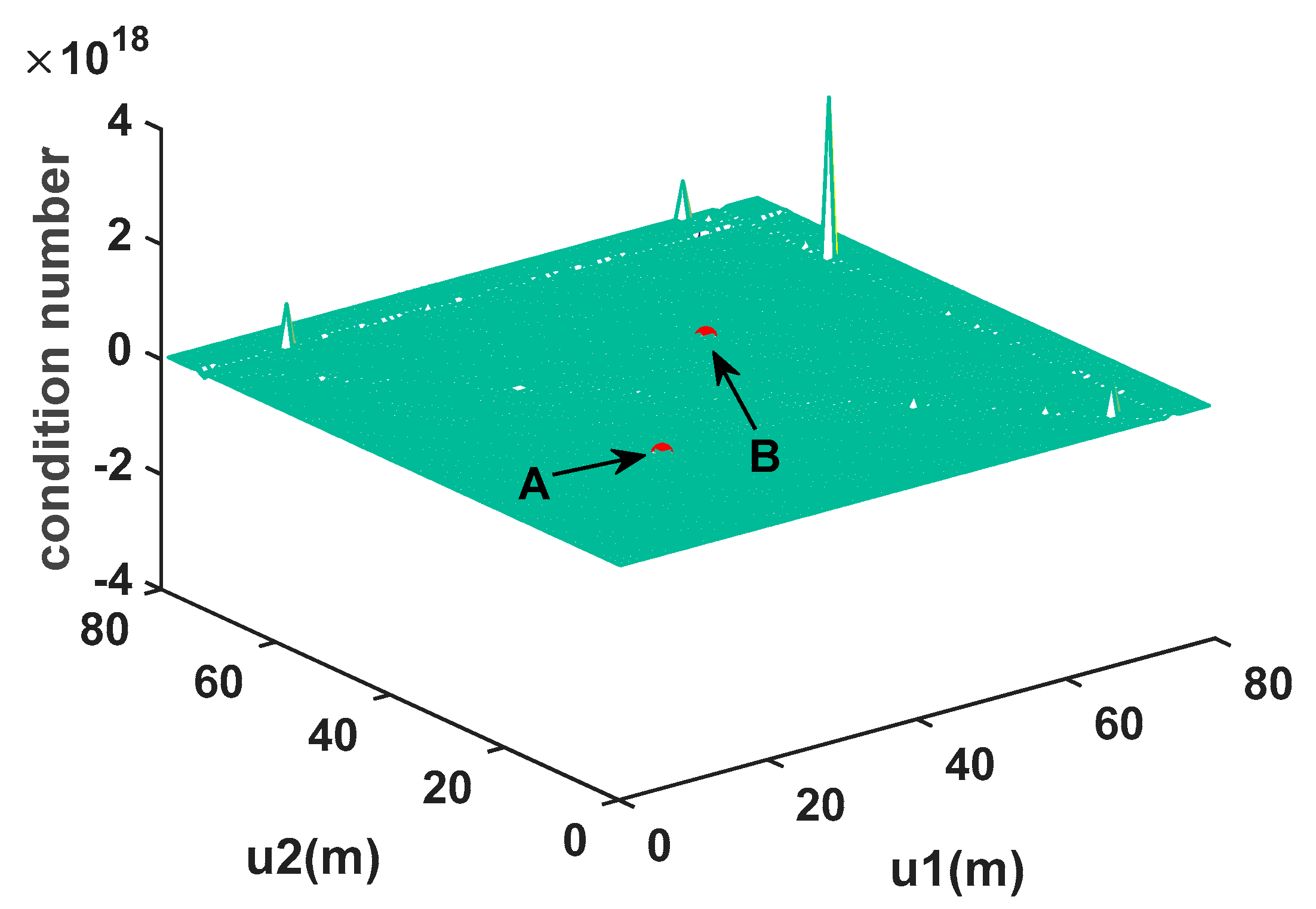
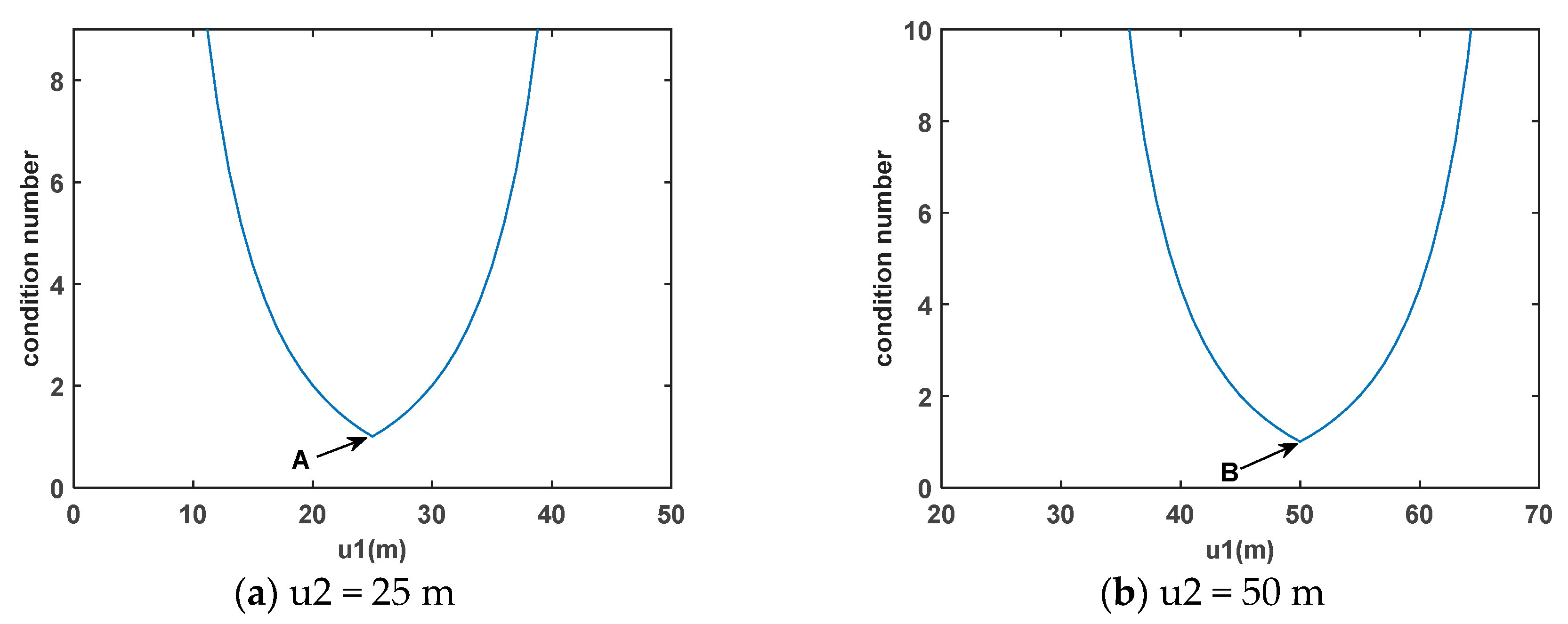
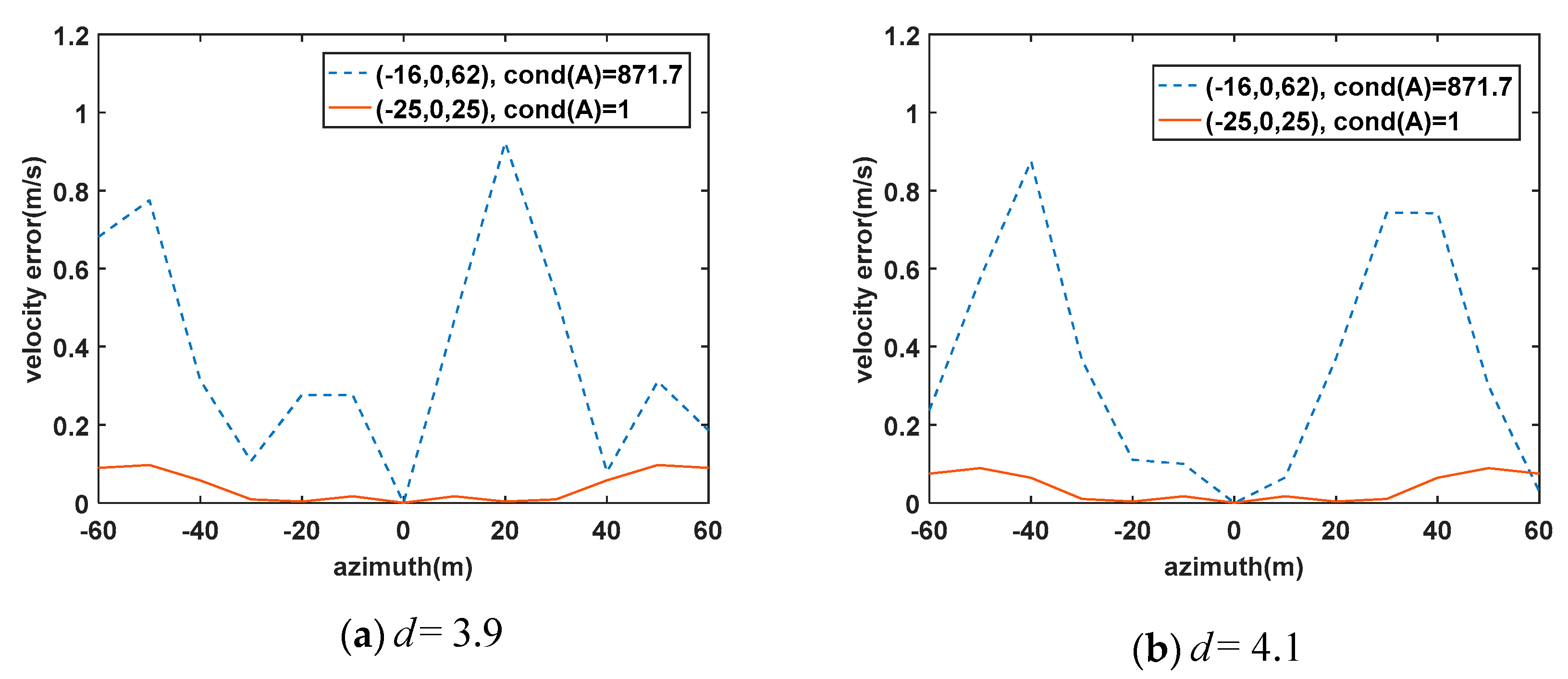
4.2. Layout optimization of Multiple Transponders

From the above analysis, we concluded that the coefficient vector Q determined whether the transponders could accurately generate false very similar targets at specified positions. If the matrix A and the vector b are disturbed, for example, the parameter R J of radar system are estimated with error, whether the vector Q can keep stable will affect the accuracy of the false targets. As we all know, the condition number c o n d ( A ) measures the sensitivity of the linear system A Q = b and represents the quality of the matrix, which can be defined as
c o n d ( A ) = A 2 A 1 2 = σ max ( A H A ) σ min ( A H A )
where 2 denotes the L2-norm, σ max ( A H A ) and σ min ( A H A ) are the maximal and minimal singular value of A H A respectively, and H is the Hermitian transpose operator. For any matrix A , the condition number c o n d ( A ) satisfies c o n d ( A ) 1 . When c o n d ( A ) is near 1, the matrix A is well-conditioned. The lager the c o n d ( A ) is, the less accurate the solution is, which would reduce the performance of jamming. Therefore, realizing the optimal layout transponders is equivalent to minimizing the condition number of matrix A with constraints. Without loss of generality, suppose x j 1 < x j 2 < x j 3 and then the optimization equation can be expressed as
min   c o n d ( A ) subject   to   { x j 2 = x c u 2 = x j 3 x j 2 L a 2 x c u 1 = x j 2 x j 1 L a 2 + x c
According to Equation (27), the coefficient matrix A is related to the azimuth coordinates of three transponders. Thus, it can change three transponders’ azimuth coordinates to achieve the optimal layout of transponders. For this, first set J 2 at x c = C , then change x j 1 , x j 3 to find the minimal c o n d ( A ) [32,33]. The SAR parameters are listed in Table 1.
After using Newton’s method optimization processing, it can be found that when c o n d ( A ) gets the minimization and is equal to 1, c o n d ( A ) is only related to u 1 and u 2 with arbitrary x j 2 . u 1 denotes the azimuth distance between transponders J 1 and J 2 , while u 2 denotes the azimuth distance between transponders J 2 and J 3 . Figure 2 gives the condition number varying with u 1 and u 2 when x j 2 = 0 . Figure 3a is the slice graph of Figure 2 in u 2 = 25 , while Figure 3b is the slice graph of Figure 2 in u 2 = 50 . According to Figure 3a,b, it can be seen that when u 1 , u 2 satisfy u 1 = u 2 = 25 and u 1 = u 2 = 50 , the condition number is equal to 1. Moreover, by searching other values of the condition number in Figure 2, we find only point A and point B satisfy c o n d ( A ) = 1 . Considering the false moving targets are easy to diverge from the imaging areas, we choose u 1 = u 2 = 25 in the following simulations.
In the optimization calculation, there are only three SAR parameters ‘Carrier frequency’, ‘Center range’ and ‘Baseline length’ in Table 1 are used. They correspond to λ , d and R J shown by Equation (27), respectively. They all can be estimated by the electronic reconnaissance system. According to these estimated parameters, the complex modulation coefficients modulated in each transponder can be calculated. But in practice, the three parameters would be estimated with errors. If the transponders continue using the layout of the transponder obtained according to the error parameter to generating jamming signals, there is going to be A Q b for the receiving antennas, and namely, b ( 2 ) = 1 , b ( 1 ) , b ( 3 ) 1 . Therefore, the phase difference between b ( 1 ) and b ( 3 ) would decide the accuracy of the velocity of the false targets. Correspondingly, the layout of the transponder would affect the accuracy of the velocity. To quantitatively evaluate the influence on the velocity caused by the estimated parameters, we consider two kinds of layout of the transponders. Using the estimated baseline d = 4.0 , we can calculate the layout of the transponders under different values of the condition number. We choose c o n d ( A ) = 1 and c o n d ( A ) = 871.7 . For c o n d ( A ) = 1 , three transponders azimuth position are −25 m, 0 m and 25 m, respectively, corresponding the optimal layout; For c o n d ( A ) = 871.7 , three transponders azimuth positions are −16 m, 0 m, and 62 m. Assume the other two parameters λ and R J are estimated accurately. Figure 4a gives the velocity error of the false target for the real baseline d = 3.9 of the three-channel SAR-GMTI, while Figure 4b gives that for d = 4.1 . The false targets distribute from −60 m to 60 m along the azimuth direction. According to Figure 4a,b, it can be seen the dotted line corresponding to c o n d ( A ) = 871.7 is above the solid line corresponding to c o n d ( A ) = 1 whether the length of the baseline is estimated larger or smaller. Therefore, when the SAR parameters are estimated with errors, the jamming performance is more robust for the optimal layout of the transponders. As for the influence on the velocity caused by the estimated parameters λ and R J , the results are the same as the d according to the characteristics of condition numbers.

5. Multiple Transponders Against Multi-Channel SAR

As described above, to obtain effective deceptive jamming against the multichannel SAR, the number of transponders should be the same as or more than the number of SAR channels. Only in this way can false targets be accurately generated without being discovered. Here, we give the general architecture of multiple transponders deceiving multichannel SAR. The deceptive jamming method against three-channel and dual-channel SAR is just a special case. According to the analysis of deceptive jamming against the three-channel SAR-GMTI, we extend it to more universal model for multichannel SAR. In this case, it is assumed that the SAR has N sensors arranged along the track direction with M transponders on the ground parallel to the track. M must satisfy M N . Then, the complex coefficient vector Q satisfies Equation (33) when the transponders works synergistically.
[ a 11 a 12 a 1 M a 21 a 22 a 2 M a e k a N 1 a N 2 a N M ] [ Q 1 Q 2 Q e Q M ] = [ b 1 b 2 b e b M ]
where a e k = exp [ j ( e W ) 2 π d λ R J ( x p x j k ) ] , b 1 = b 2 = = b M = 1 , and W is the transmitting channel number, while e is the receiving channel number. For M N , the Equation (32) must have more than one solution. Therefore, M transponders are able to deceive multichannel SAR-GMTI.
As for the multichannel InSAR, the distances among transponders must include component along the slant-range. So, for simplicity, the transponders are routed along the slant-range. Different from the SAR-GMTI, here, a e k = exp [ j 2 π λ ( R 1 k + R e k ) ] , b e = 1 = exp ( j 0 ) , b e 1 = exp ( j Δ ϕ p e ) , where R 1 k denotes the shortest distance from the transmitting channel A 1 to the transponder, R e k represents the distance between the receiving channel A e and the transponder, and Δ ϕ p e is the phase difference between two co-registration images for channel A 1 and A e at deceptive point position.
In the practical EW, the transponder performs better when the number of transponders is more than the number of SAR channels [34,35]. On the one hand, the transponder transmitting power can be further cut down and the jamming signals are more difficult to be detected. On the other hand, if one transponder doesn’t work, other transponders can continue generating deceptive jamming after being re-combined. Therefore, the robustness of the jamming system is stronger.

6. Simulations Results

The aforementioned sections have analyzed the dual-channel SAR-GMTI deceptive jamming effects and addressed procedures of generating very similar false targets against three-channel SAR-GMTI by using three synergetic transponders. In this section, to verify the effectiveness of the proposed method, simulations are provided based on a three-channel SAR-GMTI system. The system parameters have been shown in Table 1. The real image scene is an area of 200 × 200 m.
As shown in Figure 5, we set six false targets in the image scene, where the x-axis is the azimuth direction, whereas the r-axis is the range direction. They are denoted as p 1 , p 2 , p 3 , p 4 , p 5 and p 6 , whose initial coordinates and motion parameters are listed in Table 2. According to Table 2, it can be seen that p 3 and p 6 belongs to stationary targets, and the rest are moving. According to the optimal distribution of multiple transponders stated in Section 4.2, three transponders J 1 , J 2 , and J 3 are located at the same range coordinate with a 25 m interval distribution along the azimuth direction. To prevent the false moving targets from deviating the imaging areas, the transponder J 2 is place at ( 0 , 10,000 ) , and correspondingly, J 1 at ( 25 , 10,000 ) , J 3 at ( 25 , 10,000 ) as depicted in Figure 1. The corresponding complex modulation coefficients modulated in them are denoted as Q 1 , Q 2 , and Q 3 . To better describe the performance of our proposed method, two comparative experiments are also carried out. In the following simulation results, the circle indicates the false moving target position before relocation, and the square indicates the re-located moving target position.
In the first comparative experiment, only a single transponder J 2 is used to generate the jamming signals. Figure 6a shows the SAR image of channel A 2 , and six false targets are all indicated. Figure 6b,c shows the results of two-channel DPCA operation, where Figure 6b shows the result of channel A 2 and A 3 DPCA operation, while Figure 6c shows the result of channel A 1 and A 2 . It is obvious that the false stationary targets are both detected as the moving targets instead of being eliminated in Figure 6b,c. Besides, the first six rows in Table 3 exhibit the estimated velocities and azimuth positions of false targets generated by a single transponder. Apparently, the velocity of stationary targets is not equal to zero, whereas the moving targets are unequal to its setting value. As for the azimuth displacements of all detected targets, they all satisfy x p = v ^ r V a R 0 . Undoubtedly, all false targets are relocated at the same azimuth position as transponder J 2 as shown in Figure 6d. Therefore, the deceptive jamming generated by one transponder is easy to be distinguished when against three-channel SAR-GMTI.
In the second comparative experiment, two synergetic transponders J 2 and J 3 are utilized to create the deceptive jamming. According to Equation (22), the expected complex modulation coefficients Q 1 and Q 2 corresponding to two transponders J 2 and J 3 for each false target are first accurately calculated and listed in Table 4. Figure 7a shows the SAR image of channel A 2 , which all false targets are indicated. Figure 7b is the result of the channel A 2 and A 3 DPCA operation, while Figure 7c is that of the channel A 1 and A 2 . Obviously, the false stationary targets are eliminated like clutter in Figure 7b, yet not in Figure 7, which demonstrates the previous analysis accurately that two transponders can only generate very similar targets against dual-channel SAR-GMTI. If the deceptive jamming is used against three-channel SAR-GMTI, the effects would be reduced. Besides, the second six rows in Table 3 shows the estimated velocities and azimuth positions of false targets generated by two synergetic transponders, which have large errors comparing with their setting values. Besides, their azimuth positions are also not relocated the same as any transponder. Figure 7d depicts the relocation of these false targets, which differs from the distribution of false targets shown by Figure 5. Therefore, it can be concluded that deceptive jamming generated by two synergetic transponders has a limited effect against three-channel SAR-GMTI.
Last, the experiment is carried out by using our proposed method. Three transponders work synergistically. The corresponding complex modulation coefficients Q 1 , Q 2 , and Q 3 modulated in three transponders J 1 , J 2 and J 3 are calculated and listed in Table 5. In Figure 8a, the SAR image of channel A 2 , six false targets are also all indicated. Figure 8b,c shows that the false stationary targets are eliminated and only the false moving targets are reserved whether by the channel A 2 and A 3 DPCA operation or by the channel A 1 and A 2 . Besides, it is also can be seen that in the last six rows in Table 3, the estimated velocities and relocation azimuth position errors of false targets are all at the acceptable level. Figure 8d gives the imaging result of relocation, and apparently the azimuth positions of false targets coincide with the setting value comparing with Figure 5. Therefore, based on the above simulation analysis, it can be concluded that using three synergetic transponders can effectively create false targets against three-channel SAR-GMTI.

7. Conclusions

In this paper, first, using different combinations of transponders to jam the three-channel SAR-GMTI is analyzed. On the basis, we propose an effective deceptive jamming method based on three synergetic transponders. In this proposed method, it only demands each transponder is modulated with a complex modulation coefficient when generating a false target. By using three synergetic transponders, very similar false targets can be effectively created against three-channel SAR-GMTI. Compared with a single transponder or two transponders, three transponders provide enough degree of freedom equal to that of the three-channel SAR-GMTI. Meanwhile, the optimal layout of three transponders makes this jamming method more robust. Simulations have verified that the jamming method with three transponders can generate false targets with high fidelity effectively in the three-channel SAR-GMTI system. More, we also conclude that to generate deceptive false targets against multichannel SAR, the number of transponders must be greater than the number of SAR channels, including multichannel InSAR and SAR-GMTI system. Therefore, in the end of the paper, the general architecture of multiple transponders deceiving multichannel SAR is also given, which can guide the production of a deceptive digital elevation model (DEM) in multichannel InSAR as well as generate false targets against multichannel SAR-GMTI.

Author Contributions

P.J. and S.X. designed the algorithm; P.J. performed the algorithm with Matlab; D.D. and B.P. optimized the algorithm; P.J. and S.X. wrote the paper; X.W. read and revised the paper. All authors have read and agreed to the published version of the manuscript.

Funding

This research was funded by the National Natural Science Foundation of China (No. 61901499, No.61625108, No.61490693).

Conflicts of Interest

The authors declare no conflict of interest.

References

  1. Cumming, I.G.; Wong, F.H. Digital Processing of Synthetic Aperture Radar Data: Algorithm and Implementation; Artech House: Boston, MA, USA, 2004; pp. 323–362. [Google Scholar]
  2. Richards, J.A. Remote Sensing with Imaging Radar; Springer: Berlin/Heidelberg, Germany, 2009. [Google Scholar]
  3. Romeiser, R.; Suchandt, S.; Runge, H.; Steinbrecher, U.; Grunler, S. First analysis of TerraSAR-X along-track InSAR-derived current fields. IEEE Trans Geosci Remote Sens. 2009, 48, 820–829. [Google Scholar] [CrossRef]
  4. Cerutti-Maori, D.; Sikaneta, I. A generalization of DPCA processing for multichannel SAR/GMTI radars. IEEE Trans. Geosci. Remote Sens. 2012, 51, 560–572. [Google Scholar] [CrossRef]
  5. Dudczyk, J.; Kawalec, A. Optimizing the minimum cost flow algorithm for the phase unwrapping process in SAR radar. Bulletin. Pol. Aca. Sci. Tech. Sci. 2014, 62, 511–516. [Google Scholar] [CrossRef] [Green Version]
  6. Rosenberg, L.; Gray, D. Anti-jamming techniques for multichannel SAR imaging. IEE Radar Sonar Navig. 2006, 153, 782–786. [Google Scholar] [CrossRef] [Green Version]
  7. Sjögren, T.K.; Vu, V.T.; Pettersson, M.I.; Wang, F.; Murdin, D.J.G.; Gustavsson, A.; Ulander, L.M. Suppression of clutter in multichannel SAR GMTI. IEEE Trans Geosci Remote Sens. 2013, 52, 4005–4013. [Google Scholar] [CrossRef]
  8. Matuszewski, J. Evaluation of jamming efficiency for the protection of a single ground object. Proc. SPIE 2018, 10715, 1. [Google Scholar]
  9. Matuszewski, J. Jamming Efficiency of Land-Based Radars by the Airborne Jammers. In Proceedings of the MIKON 2018—22nd International Microwave and Radar Conference, Poznan, Poland, 14–17 May 2018; pp. 324–327. [Google Scholar]
  10. Ferraioli, G. Multichannel InSAR building edge detection. IEEE Trans Geosci Remote Sens. 2009, 48, 1224–1231. [Google Scholar] [CrossRef]
  11. Schroer, R. Electronic warfare. IEEE Aerosp. Electron. Syst. Mag. 2003, 18, 49–54. [Google Scholar]
  12. Neng-Jing, L.; Yi-Ting, Z. A survey of radar ECM and ECCM. IEEE Trans. Aerosp. Electron. Syst. 1995, 31, 1110–1120. [Google Scholar] [CrossRef]
  13. Harness, R.S.; Budge, M.C. A study on SAR noise jamming and false target insertion. In Proceedings of the IEEE SoutheastCon, Lexington, KY, USA, 13–16 March 2014; pp. 1–8. [Google Scholar]
  14. Pace, P.E.; Fouts, D.J.; Ekestorm, S.; Karow, C. Digital false-target image synthesiser for countering ISAR. IEE Radar Sonar Navig. 2002, 149, 248–257. [Google Scholar] [CrossRef]
  15. Dai, D.H.; Wu, X.F.; Wang, X.S.; Xiao, S.P. SAR active-decoys jamming based on DRFM. In Proceedings of the 2007 IET International Conference on Radar Systems 2007, Edinburgh, UK, 15–18 October 2007; pp. 15–18. [Google Scholar]
  16. Huang, L.; Dong, C.; Shen, Z.; Zhao, G. The influence of rebound jamming on SAR GMTI. IEEE Geosci. Remote Sens. Lett. 2014, 12, 399–403. [Google Scholar] [CrossRef]
  17. Dong, C.; Chang, X. A novel scattered wave deception jamming against three channel SAR GMTI. IEEE Access. 2018, 6, 53882–53889. [Google Scholar] [CrossRef]
  18. Liu, Y.; Wang, W.; Pan, X.; Dai, D.; Feng, D. A frequency-domain three-stage algorithm for active deception jamming against synthetic aperture radar. IET Radar Sonar Navig. 2014, 8, 639–646. [Google Scholar] [CrossRef]
  19. Zhou, F.; Zhao, B.; Tao, M.; Bai, X.; Chen, B.; Sun, G. A large scene deceptive jamming method for space-borne SAR. IEEE Trans. Geosci. Remote Sens. 2013, 51, 4486–4495. [Google Scholar] [CrossRef]
  20. Xu, H.; Wu, Z.; Liu, W.; Li, J.; Feng, Q. Analysis of the effect of interference on InSAR. IEEE Sens. J. 2015, 15, 5659–5668. [Google Scholar] [CrossRef] [Green Version]
  21. Chunxi, D.; Guoqing, Z. Investigation on countermeasure against InSAR dual-channel cancellation technique with multi-antenna transponder. J. Electron. Inf. Technol. 2015, 37, 913–918. [Google Scholar]
  22. Gan, R.B.; Wang, J.G.; He, C.; Xu, M.L. An improved rebound jamming to SAR. J. Electron. Inf. Technol. 2005, 27, 256–258. [Google Scholar]
  23. Tang, B.; Guo, K.; Wang, J. The 3D Active Deception Jamming of SAR. Acta Electron. Sin. 2007, 35, 1203–1206. [Google Scholar]
  24. Zhang, J.; Dai, D.; Qi, Z.; Zeng, Y.; Xiao, S. Analysis of deceptive moving target generated by single transponder in multichannel SAR-GMTI. In Proceedings of the 2017 International Applied Computational Electromagnetics Society Symposium (ACES), Suzhou, China, 1–4 August 2017; pp. 1–2. [Google Scholar]
  25. Chang, X.; Dong, C. A Barrage Noise Jamming Method Based on Two Transponders Against Three Channel SAR GMTI. IEEE Access. 2019, 7, 18755–18763. [Google Scholar] [CrossRef]
  26. Zhang, J.; Xing, S.; Dai, D.; Li, Y.; Xiao, S. Three-dimensional deceptive scene generation against single-pass InSAR based on coherent transponders. IET Radar Sonar Navig. 2016, 10, 477–487. [Google Scholar] [CrossRef]
  27. Wu, Z.-F.; Xu, H.-P.; Li, J.-W.; Liu, W. Research of 3-D deceptive interfering method for single-pass spaceborne InSAR. IEEE Trans. Aerosp. Electron. Syst. 2015, 51, 2834–2846. [Google Scholar] [CrossRef]
  28. Zhang, J.; Qi, Z.; Zeng, Y.; Wang, L. Deceptive jamming against multi-channel SAR-GMTI. J. Eng. 2019, 20, 7105–7109. [Google Scholar] [CrossRef]
  29. Sun, Q.; Shu, T.; Yu, K.-B.; Yu, W. A Novel Deceptive Jamming Method against Two-Channel SAR-GMTI Based on Two Transponders. IEEE Sens. J. 2019, 19, 5600–5610. [Google Scholar] [CrossRef]
  30. Deming, R.; Best, M.; Farrell, S. Simultaneous SAR and GMTI using ATI/DPCA. In Algorithms for Synthetic Aperture Radar Imagery XXI, Proceedings of the SPIE, Baltimore, MD, USA, 5–9 May 2014; International Society for Optics and Photonics: Bellingham, WA, USA, 2014; Volume 9093, p. 19. [Google Scholar]
  31. Livingstone, C.; Sikaneta, I.; Gierull, C.H.; Chiu, S.; Beaudoin, A.; Campbell, J.; Beaudoin, J.; Gong, S.; Knight, T.A. An airborne synthetic aperture radar (SAR) experiment to support RADARSAT-2 ground moving target indication (GMTI). Can. J. Remote Sens. 2002, 28, 794–813. [Google Scholar] [CrossRef]
  32. Zhou, F.; Tian, T.; Zhao, B.; Bai, X.; Fan, W. Deception Against Near-Field Synthetic Aperture Radar Using Networked Jammers. IEEE Trans. Aerosp. Electron. Syst. 2019, 55, 3365–3377. [Google Scholar] [CrossRef]
  33. Zhao, B.; Huang, L.; Zhou, F.; Zhang, J. Performance improvement of deception jamming against SAR based on minimum condition number. IEEE J. Sel. Top Appl. Earth Obs. Remote Sens. 2016, 10, 1039–1055. [Google Scholar] [CrossRef]
  34. Adamy, D.L. Digital RF Memories. In EW 104: EW against a New Generation of Threats; Artech House: Norwood, MA, USA, 2015. [Google Scholar]
  35. Schleher, D.C. Introduction to Electronic Warfare; IEEE Press: Dedham, MA, USA, 2004. [Google Scholar]
Figure 1. Geometry of three-channel SAR-GMTI.
Electronics 09 00597 g001
Figure 2. Surface Plot of condition number varying with u 1 and u 2 when x j 2 = 0 .
Electronics 09 00597 g002
Figure 3. The slice graph of Figure 2.
Electronics 09 00597 g003
Figure 4. The influence on the velocity caused by the estimated baseline d .
Electronics 09 00597 g004
Figure 5. Distribution of false targets.
Electronics 09 00597 g005
Figure 6. Simulations of false targets generated by one transponder. (a) is the SAR image of channel A 2 ; (b) is the result of the channel A 2 and A 3 DPCA operation; (c) is the result of the channel A 1 and A 2 DPCA operation; (d) is the relocation result.
Electronics 09 00597 g006
Figure 7. Simulations of false targets generated by two transponders. (a) is the SAR image of channel A 2 ; (b) is the result of the channel A 2 and A 3 DPCA operation; (c) is the result of the channel A 1 and A 2 DPCA operation; (d) is the relocation result.
Electronics 09 00597 g007
Figure 8. Simulations of false targets generated by three transponders. (a) is the SAR image of channel A 2 ; (b) is the result of the channel A 2 and A 3 DPCA operation; (c) is the result of the channel A 1 and A 2 DPCA operation; (d) is the relocation result.
Electronics 09 00597 g008
Table 1. Parameters of three-channel SAR-GMTI.
ParametersValue
Carrier frequency10 GHz
Bandwidth70 MHz
Beam width0.5o
Platform velocity250 m/s
Numbers of channel3
PRF1000 Hz
Center range10,000 m
Baseline length4 m
Table 2. The coordinates and velocity of the false point target.
Targets p 1 p 2 p 3 p 4 p 5 p 6
Coordinates ( 40 , 10,040 ) ( 15 , 10,040 ) ( 30 , 10,020 ) ( 45 , 9960 ) ( 10 , 9960 ) ( 45 , 9980 )
v r ( m / s ) −0.5 0.7 00.4 −0.6 0
Table 3. Radial velocity and azimuth position of false targets with different combinations of transponders.
IndexRadial VelocityAzimuth Position
Estimation v ^ r (m/s)Error (m/s)Estimation x ^ (m)Displacement R 0 v ^ r / V a (m)Relocation (m)Error (m)
A single transponderP1−1.5−160.2600.239.8
P21.0750.375−43−430−15
P30.750.75−29.9−300.1−30.1
P41.5251.125−60.8−610.2−45.2
P5−0.85−0.253434010
P6−1.125−1.12545.2450.244.8
Two transpondersP1−0.3060−0.194060.41248.4−8.4
P20.77700.0770−43−31.08−11.92−3.08
P30.81440.8144−29.4−32.382.98−32.98
P40.25910.1409−61.310.36−50.945.94
P5−0.8160−0.216033.732.641.068.94
P6−0.8132−0.813245.632.5313.1731.83
Three transpondersP1−0.5380.03860.221.5238.681.32
P20.70880.0088−42.8−28.35−14.45−0.55
P30.01350.0135−29.9−0.54−29.36−0.64
P40.38620.0138−60.8−15.45−45.350.35
P5−0.6314−0.031433.725.268.441.56
P6−0.0281−0.028145.21.1244.080.92
Table 4. Complex coefficients of different false targets corresponding to two transponders.
TargetsP1P2P3
Q 2 0.0709 − 0.6750i0.9291 − 0.6750i0.2652 − 0.8161i
Q 3 0.9291 + 0.6750i0.0709 + 0.6750i0.7348 + 0.8161i
TargetsP4P5P6
Q 1 −0.0742 − 0.2283i0.6200 + 0.2761i0.1606 + 0.1784i
Q 2 1.0742 + 0.2283i0.3800 − 0.2761i0.8394 − 0.1784i
Table 5. Complex coefficients of different false targets corresponding to three transponders.
TargetsP1P2P3
Q 1 −0.3188 + 0.0000i0.5393 + 0.0000i−0.2060 − 0.0000i
Q 2 0.5393 + 0.0000i−0.3188 + 0.0000i0.2636 + 0.0000i
Q 3 0.7794 − 0.0000i0.7794 − 0.0000i0.9424 + 0.0000i
TargetsP4P5P6
Q 1 −0.2060 − 0.0000i0.7794 − 0.0000i0.2636 + 0.0000i
Q 2 0.9424 + 0.0000i0.5393 − 0.0000i0.9424 − 0.0000i
Q 3 0.2636 − 0.0000i−0.3188 + 0.0000i−0.2060 − 0.0000i

