1. Introduction
An industrial control system (ICS) is a kind of control system dedicated to industrial process control. It plays critical roles in manufacturing plants and infrastructures such as car assembly plants, chemical plants, and even nuclear power plants. These control systems are commonly safety-critical, whose failures may cause major economic losses, human casualties or even disasters. Therefore, it is necessary to verify the safety of industrial control systems.
As the core component of most ICSs, the programmable logic controller (PLC) is one of the most important points of concern. Generally, problems of PLC can be divided into two categories: hardware-raised and software-raised. The hardware-raised problems usually can be detected or avoided by verification using simulation, redundant mechanisms, and built-in diagnostics. The software-raised problems can be discovered by testing, simulation and formal verification for PLC programs. In this paper, we are mainly concerned with the solution to ensure the safety of PLC software.
Testing and simulation are straightforward, but it is hard to ensure that a PLC program completely fulfills its specifications. Moreover, it is usually difficult to find defects raised by complex causes using testing and simulation. For example, assuming that there are some interdependent signals in a control loop, an error may occur if a boolean signal s1 does not remain true before another signal s2 comes. The cause of this kind of problem is usually difficult to be observed directly from the test or simulation process. As functions of PLC programs and interactions of multiple PLCs become more and more complex, these methods will become increasingly ineffective.
As a supplementary technique, formal verification is considered to be a recommended method to prove the absence of some specific bugs and the satisfiability of some good properties. Formal verification mainly consists of deductive verification and model checking. The former proves properties that the PLC programs should hold through converting these problems into some target theorems and then mechanically proving them with the help of interactive theorem provers, automated theorem provers, or satisfiability modulo theories (SMT) solvers. The latter first transforms a PLC program into an automaton, and then exhaustively searches the state space of the automaton to check the satisfiability of some property.
There are some attempts to use deductive verification to prove the correctness of PLC programs [
1,
2]. However, since deductive verification requires strong professional knowledge and heavy manual work, it is still not widely used in practice. Therefore, most research works focus on model checking of PLC [
3,
4,
5,
6,
7,
8,
9,
10,
11,
12]. Almost all of them follow the following pattern: firstly, transforming the PLC program written in one specific PLC language into some formal model; secondly, expressing the system property in a specific formal language which is not ambiguous (The formal expression of the property is usually called formal specification.); thirdly, using an existing model checker to check the property against the model. Although model checking is highly automated, formal modeling and specification writing are difficult and complex for control engineers without related expertise. These expertise requirements are exactly the main obstacle to the widespread use of model checking. In particular, verification for different kinds of properties requires different formal models. Some researchers studied the automatic generation of formal models from existing PLC programs [
5,
7] and some work proposed specification mining to automatically infer systems’ specifications [
13,
14], but no work has combined them yet and no tools are available publicly. Moreover, with the increasing complexity of industrial control systems, the state space of the corresponding formal models will grow rapidly, which may lead to a state explosion problem, making the model checking process impossible to be completed in limited time and memory space [
15]. This will further limit the scalability and practicability of model checking.
1.1. Contribution
In this paper, we present a user-friendly verification approach for IEC 61131-3 PLC programs. It combines simulation with specification mining to supplement traditional simulation and model checking for usability, practicability, and efficiency. As far as we know, we are the first to formally propose this approach. Furthermore, we introduce a proof-of-concept implementation named PLCInspector. Based on this implementation, a PLC program written in structured text (ST)/instruction list (IL)/sequential functional chart (SFC) can be directly compiled into a soft-PLC x86 executable, and then this executable can be directly executed and logged on an x86 computer. Finally, linear temporal logic (LTL) specifications and data invariants will be automatically mined from the execution log. The entire process can be completed with only one click. Since these LTL specifications and data invariants can reflect the properties of the program to some extent, control engineers can check their implementations by reviewing these properties. Both the presence of undesirable properties and the absence of desirable properties can be regarded as errors or defects. Two simple examples and one real-life case study are present to illustrate its feasibility, practicability, and efficiency. In addition, we discuss the advantages and disadvantages of this approach against traditional testing, simulation, and model checking.
1.2. Related Work
There are a variety of studies and research projects that have been performed for quality improvement of PLC programs. In general, approaches to improving program quality can be roughly divided into three categories: testing, simulation, and formal verification.
In terms of testing, References [
16,
17,
18] made efforts to get rid of writing exhaustive tests for PLC programs. Simon et al. [
16] presented an open-loop technique that aided the developer in writing specific PLC test cases that could cover all lines or all conditional branches of the program. Bohlender et al. [
17] proposed an automated, symbolic execution-based approach to generate high-coverage test cases without demanding complex user interactions for programs that met the IEC 61131-3 standard. Li Hao et al. [
18] presented an automated test case generation approach for ST (structured text) programs using dynamic symbolic execution. Besides, References [
19,
20] provided model-based automatic test methods. However, these test methods require the user to establish formal models first.
As for simulation, [
21] proposed a PLC programming environment architecture, which realized the visual verification of PLC programs. Ref. [
22] presented a framework of virtual plant models for the verification of PLC logic through modeling and simulation. Moreover, a method for automatically generating a plant model from the symbol table of a PLC program based on naming rules that contain sufficient information on the plant model was proposed in [
23]. These methods are necessary, but they are relatively heavyweight and costly.
Many works attempted to apply formal methods to the verification of PLC programs, mainly adopting model checking [
2,
3,
4,
6,
7,
9,
11,
24,
25,
26,
27,
28,
29,
30,
31,
32,
33]. Most of the work focused on the formal representation and verification of PLC programs written in one of the languages of the IEC 61131-3 standard. Ref. [
2] provided the semantics of SFC and IL, formalized in the proof assistant Coq, while [
3,
27] discussed their verification based on model checking. Ref. [
29] present a proposal for the modeling of extended finite state machines from control programs written in LD. Ref. [
4,
30,
31] targeted the formal verification for FBD. Ref. [
7] presented a method to transfer ST programs automatically to formal models and [
6] performed the verification of timing aspects for real-life PLC programs using NuSMV. Ref. [
33] introduced a compositional approach to the multi-level behavior modeling and formal validation of large-scale distributed systems operations using hierarchies and networks of finite state automata. Meanwhile, the work in [
11] mentioned that all PLC languages could be represented in ST, which can be verified by ST-based PLCverif model checking tools. These efforts all attempt to solve the modeling problem, but writing formal specifications is still difficult for engineers without related expertise.
In addition, to better understand the behavior of systems and programs, some works proposed specification mining techniques. In [
13], Ammons et al. first described specification mining as a promising approach to improving program quality and proposed a tool to summarize the frequent interaction patterns as state machine by observing program execution. In [
34], Weimer et al. presented an automatic specification mining algorithm to learn temporal safety rules from information about error handling. In [
35], Yang et al provided a tool named Perracotta to mine eight different kinds of temporal properties that cover common program patterns. Li et al. extended Perracotta to mine simple LTL patterns from traces to diagnose digital circuit [
36]. In [
14], Lemieux et al. presented the general LTL specification miner Texada, which replaces a suite of tools that are based on specific templates and supports tasks ranging from log exploration to property validation.
In [
37], Grimm et al. studied six well-established techniques that exist to verify hardware and concluded that a hybrid approach offers the best balance between simulation (time) and formal verification (resources). Our proposal is such a hybrid verification approach for PLC programs, which attempts to combine testing or simulation and formal specification mining to directly provide evidence for verification. To our best knowledge, we are the first formally present this approach. Compared with traditional testing, simulation, and formal verification, our approach is more concise and easy to use for test engineers and has good extensibility. Any new work on test case generation, simulation and specification mining can be combined into it.
2. Preliminary
2.1. PLC and IEC 61131-3
PLC is the most widely used controller device in industrial control systems and PLC programs are necessary and fundamental elements for the modern industrial world. IEC 61131-3 is the third part (of 10) of the open international standard IEC 61131 for programmable logic controllers. It deals with the basic software model and programming languages of the control programs within PLC. Following this standard makes our approach more practical and extensible.
The PLC software model of IEC 61131-3 standard can be represented in a hierarchical structure. The top element is Configuration. A Configuration is the whole application of a PLC device. A Configuration consists of one or more Resources, which can be seen as virtual machines in a physical machine. Each Resource supports multiple Tasks. A Task is a schedulable instance bounded with a specific PLC program. There may be multiple tasks running at different cycles on the same PLC.
In contrast to general-purpose computer programs, PLC programs are typically executed cyclically. Each cycle (so-called scan cycle) consists of three phases as follows:
INPUT: reading the values from input ports and keeping these values in the memory (i.e., input variables).
EXECUTION: executing the program code with these input values.
OUTPUT: flushing the values in the memory out to physical output ports.
Since there may be some static variables in PLC programs, the execution of each cycle may depend on the execution of previous cycles, which will complicate the analysis and verification of the PLC program. Therefore, the special execution mechanism must be considered for PLC program verification.
According to the IEC 61131-3 standard, there are five programming languages for PLC, i.e., Ladder Diagram (LD), Function Block Diagram (FBD), Instruction List (IL), Structured Text (ST), and Sequential Function Chart (SFC). IL and ST are textual languages. IL is a low-level language, e.g., assembly language. ST is an advanced language, e.g., C. It is worth mentioning that Darvas et al. [
11] provide a translation method from IL to ST programming languages. LD, FBD, and SFC are graphical languages that are more intuitive.
2.2. Linear Temporal Logic
Linear temporal logic (LTL) is a temporal modal logic with modal operators about time. LTL has the following syntax given in Backus Naur form:
where
p is a proposition atom from some set Atoms which stands for atomic facts which may be held by a system, such as “The value of input variable
is 0”.
The operators X, F, G, U, R, and W are temporal operators. Each of them is used to describe a temporal relationship between two propositions:
Until, holds if there is an event in the trace where holds and if is true on all events up to the first event where holds.
Next, holds if is true on the next event from the current event.
Finally/Eventually, holds if there exists a future event in the trace where is true.
Globally/Always, holds on a trace if holds on all future events from the start event.
Weak Until
Release
For example, “” expresses that the value of “IX0.0” is always equal to 0.
LTL is extensively used in model checking as it can express some bad things which should never happen (safety property), some good things which should eventually happen (liveness property), and some more complex property combining safety properties and liveness properties.
2.3. Data Invariant
Data Invariant plays an important role in maintaining program correctness and aiding system comprehension. In a program, a data invariant is a program property that is always true. Specifically, data invariants mainly refer to the possible value ranges of variables and the relationship between variables. For example, in a program, the value of a variable a is always larger than 10 (i.e., ), the value of variable a is always equal to the value of variable b (i.e., ), or the value of temperature variable t is always in the range of 0 to 100 (i.e., ). In a PLC program, it may indicate the angle range of rotation of a motor or the temperature range sensed by a sensor.
2.4. Specification Mining
A specification is a property that a system should hold. Specification Mining is a mechanized procedure for systematically mining specifications from the real behaviors of the system under verification. It is helpful to address several challenges in verification, such as assisting in program understanding, bug finding and providing specifications for further formal verification. Specifically, in this paper, we exploit two open-source tools—Texada and Daikon for mining LTL specifications and data invariants, both of which can effectively uncover characteristics of PLC programs. The following are some important definitions in specification mining:
Event: An event is a set of simple facts or propositions satisfied at some point in time. In practice, an event may be a string or a set of strings.
Trace: A trace is a sequence of events.
Log: A Log is composed of several traces.
4. Implementation
In this section, we will introduce the proof-of-concept implementation named PLCInspector for our proposed approach.
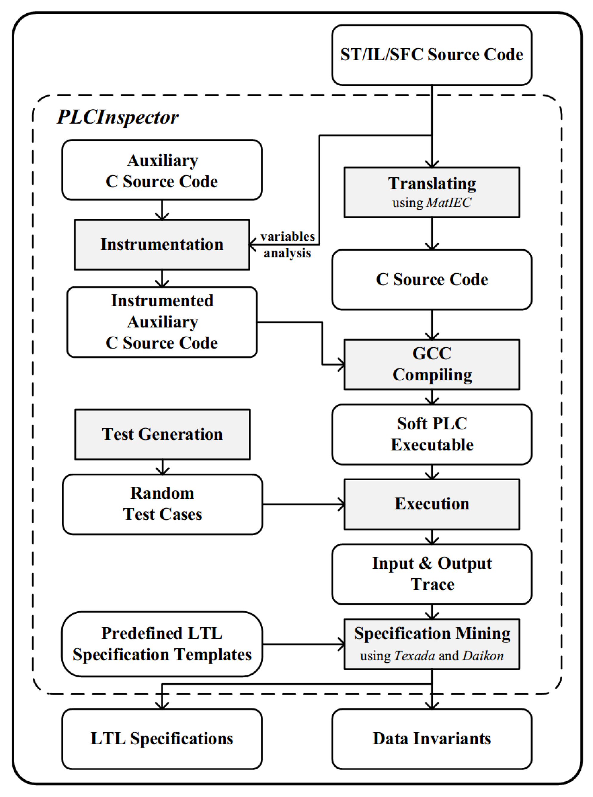
As depicted in
Figure 3, the workflow of this implementation is presented. The ST/IL/SFC source code with configuration information is directly fed and translated into C source code. Then the input and output variables of the PLC program will be discovered and analyzed. The source code for recording variable values will be auto-generated and instrumented into our customized auxiliary C source code. Test cases can be generated simultaneously. With this auxiliary source code, the C source code of the PLC program will be compiled into an x86 executable that has the same behaviors as the original PLC program. To get the execution log, this x86 executable will be executed with the generated test cases. Finally, specification miners are invoked, and then all satisfied specifications over the execution log will be produced. The whole process is controlled by a script program. More details are described below.
4.1. Test Case Generation
For simplicity, at the moment, we implement a random test case generator which is written in a python script. This generator will automatically analyze the variables and generate random values for different types of variables. Given several cycles, the generator will generate an input value sequence of that length. Each input in this sequence is a group of random values of the input variables of the target PLC system.
4.2. Execution
For better control of the execution and the simplicity of implementation, we built our own softPLC based on the MatIEC project [
38] which is an open-source compiler project for the programming languages defined in the IEC 61131-3 standard. Currently, it supports translation from ST/IL/SFC source code to C source code. Therefore, our implementation inherits the capability to process the PLC programs written in these three languages. The PLC source code written in these languages would first be translated into an equivalent C source code. Then these C source files can be compiled with our customized auxiliary C framework using GCC. In the end, a softPLC executable will be generated. This executable can directly run on an x86 personal computer. This executable can completely simulate the behaviours of a PLC configuration that supports multiple tasks. In a simulation, the executable will read the PLC program input from a specific file and write the output into another specific file.
4.3. Logging
In our softPLC, some code generated by our script is instrumented to record values of the input and output variables of each tick. Tick is a time unit. The time value of a tick is the greatest common divisor of the cycles of multiple tasks. For example, if there is only one task with a cycle of 50 ms, the tick will be 50 ms. If there is another task with a cycle of 20 ms in the PLC configuration, the tick will be 10 ms. Those values of input and output are recorded as a time sequence with this tick.
4.4. LTL Specification Mining
In our implementation, we choose LTL properties and Data Invariants as our target specifications. In model checking, users have to manually compose LTL specifications according to the requirements, which is tedious and requires expertise and experience. In this work, we use a general LTL specification miner named Texada [
14] to automatically mine specifications. It requires three inputs: a log file composed of multiple time sequences of values of input and output variables, several LTL property templates, and a threshold (a
confidence value and a
support value). A part of predefined LTL property templates are shown in
Table 1. The
support and
confidence threshold can control the degree of the satisfiability of some property specification over the log, which means some imperfect specification can also be mined if the
confidence is not 1. If the
confidence is set to 0.5, the candidate specification only needs to satisfy over more than half the number of traces. The
support is the minimum number of traces over which the specification should satisfy. The output of
Texada is a set of LTL specifications which are satisfied over the log and above the given threshold. In a specification mining procedure,
Texada will generate all property instances (or specification instances) based on the input property templates and the set of events in the log on the fly. Whenever a property instance is generated, Texada will check it over all the time sequences of the log. If the number of time sequences that satisfy a property instance is larger than the
support value and the ratio of these time sequences to the total number of time sequences is larger than the
confidence value, this candidate property instance can be seen as a valid property specification.
4.5. Data Invariant Detection
We choose Daikon as our invariants miner.
Daikon is an implementation of the dynamic detection of likely invariants. Dynamic invariant detection runs a program, observes the values that the program computes, and then reports properties that are true over the observed executions. However, this tool cannot be directly used, since the object we are mining is not a program but a log. In this implementation, we write a dedicated preprocessing script to generate different input for Texada and Daikon respectively.
5. Experiments and Results
In this section, we present two examples and one real-life case study to illustrate the practicability of the implementation. In addition, a performance evaluation was conducted to show its efficiency. This implementation and related examples were packaged into a docker container and the image was pushed on Docker Hub (
https://hub.docker.com/repository/docker/jiawenxiong/lwplcv).
5.1. A Toggle
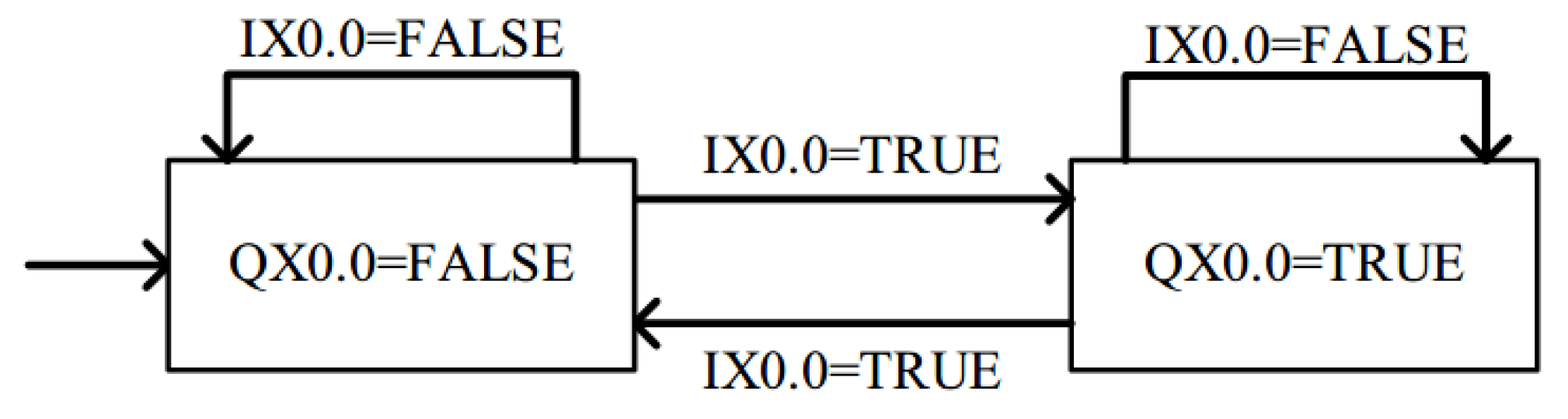
A toggle is a functional block with one boolean input variable, one boolean output variable, and one static inner boolean variable. Initially, the value of the output is FALSE. Each TRUE value of the input variable will change the value of the output variable, otherwise, the output will keep the last value. The state graph of the toggle is depicted as
Figure 4.
We write a PLC program to implement this switch, randomly generate a test input of 2000 cycles, compile this program to x86 executable, execute this program with this test case, and run Texada with a LTL templates G((a & Xb) -> c) on the execution log. In the end, we get four LTL specifications as follows:
G((“QX0.0 = FALSE” & X“IX0.0 = TRUE”) -> X“QX0.0 = TRUE”)
G((“QX0.0 = FALSE” & X“QX0.0 = TRUE”) -> X“IX0.0 = TRUE”)
G((“QX0.0 = TRUE” & X“IX0.0 = TRUE”) -> X“QX0.0 = FALSE”)
G((“QX0.0 = TRUE” & X“QX0.0 = FALSE”) -> X“IX0.0 = TRUE”)
where “IX0.0” is the input variable and “QX0.0” is the output variable. According to the first and the third specifications, we know that once “IX0.0 = TRUE” appears, the variable “QX0.0” must be negated. According to the second and the forth specifications, we know that if the variable “QX0.0” is negated, the “IX0.0 = TRUE” must be true.
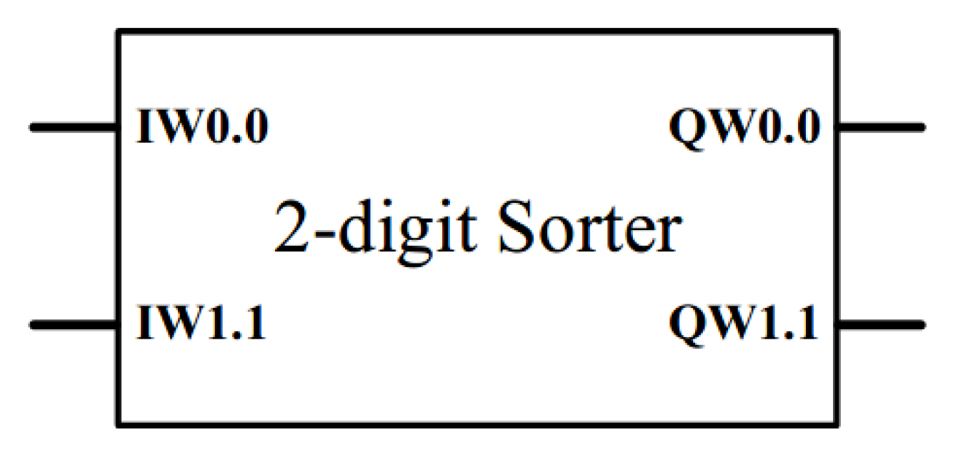
5.2. A 2-Digit Sorter
To illustrate the role of the invariant detection, we implement a 2-digit Sorter which can sort two real numbers.
This program has two input variables “IW0.0”, “IW1.1” and two output variables “QW0.0”, “QW1.1” as depicted in
Figure 5. As two numbers are read, the bigger number will be output from the first output variable, and the smaller number will be output from the second output variable. For this program, we also generate a test input of 2000 cycles. In the experiment, we get invariants as follows:
“IW0.0” != “IW1.1”
“IW0.0” <= “QW0.0”
“IW0.0” >= “QW1.1”
“IW1.1” <= “QW0.0”
“IW1.1” >= “QW1.1”
“QW0.0” >“QW1.1”
According to the first invariant, we know these test cases do not contain the case in which the first input value is equal to the second input value. The 2–5 invariants indicate our implementation meets our requirements. Obviously, the 6th invariant can be derived from the previous invariants.
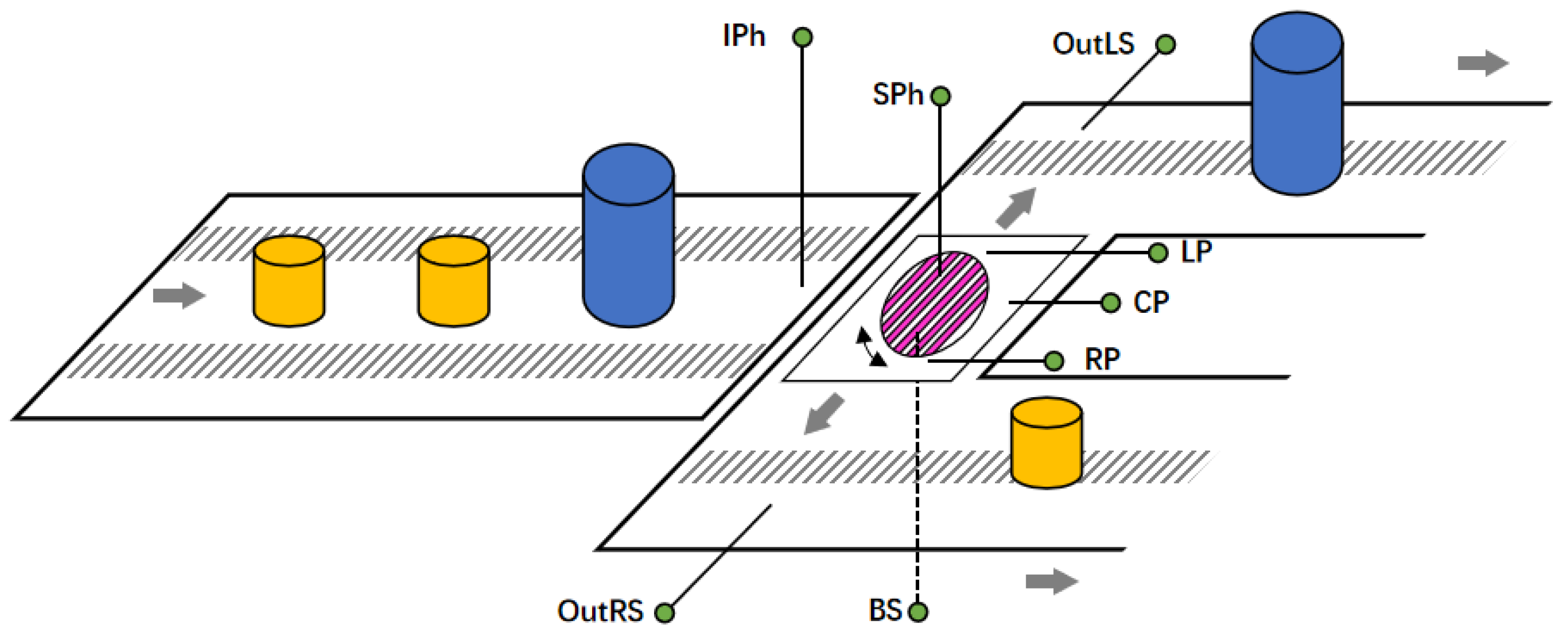
5.3. A Real-Life Case Study
As shown in
Figure 6, a product sorter is used to sort products by size and it is composed of two parts: a conveyer and a rotating platform. Products are transmitted to the rotating platform and then are sorted to different sides of the rotating platform: big ones to the left side and small ones to the right. The position and size of products are identified by several photoelectric sensors. After sensor IPh detects a product entering the platform, a motor starts to drive the rollers beneath the platform and the product is moved to the center of the platform. When sensor BS confirms the location of the product, the motor stops and sensor SPh begins to measure the height of the product.
The platform rotates by 90 degrees towards the corresponding direction based on the measured size. The product is then sent out by rollers until sensor LP/RP detects that the product arrives at the exit on each side. Then, the product is moved away by another motor till sensor OutLS/OutRS detects the unloaded product and informs the platform to rotate back to original direction to wait for the next product.
As shown in
Figure 7, we design a state machine of the product sorter. The signals of the sensors are represented by boolean variables. The transition between states happens when the boolean expression is fulfilled. In each state, there are some operations. We implemented its control program in SFC language and ST language. It is easy to compose this program under the guidance of the state machine.
After programming, we input the source code into PLCInspector. Finally, we found some problems in the actual implementation. Part of the problems stemmed from the design of the system itself, and part of the problems stemmed from negligence in the implementation process. For example, we did not get a specification G(IPh → X ¬ IPh), which means that the state Load_1 failed to transfering to the state Load_2 sometimes. By analyzing the log, we found that IPh can still be assigned to TRUE after the operations in the state Load_1 are completed, because the value of the input variable IPh is randomly assigned. In a real-life situation, after the operations in the state Load_1 are performed, a new product that is very close to the previous product can be transmitted to the position under the sensor IPh, which will immediately change the value of IPh back to TRUE, then makes the product sorter enter an abnormal state. In addition, we achieved a specification G(LP ∧ BS) which means RP and BS had never happened. Therefore, all products were moved to the left side. According to the mined data invariant SPh ∈ {TRUE,FALSE}, we knew that the SPh was not always TRUE. Therefore, some products should be moved to the right side. Finally, we found that we miswrote the transition condition BS AND NOT SPh as the transition condition BS AND SPh between the state Load_2 and the state Move Right.
5.4. Performance Evaluation
Since our methods have no reference standards and no open tools for us to compare, we only show the time required to process the two examples and the real-life case study above.
All the experiments are performed on a virtual machine running a 64-bit Ubuntu 18.04 operating system with 8GB memory and four virtual cores on a physical machine with 2 Intel Xeon E5-2690 processors. Each time value is the average of ten operations.
As shown in
Table 2, the time of Testing and Logging seems to be the most stable. In fact, each task of the PLC programs was set to execute at a 1ms cycle. It should take about 2000 ms for 2000 cycles. Therefore, the efficiency of simulation is actually quite good. As for the time of specification mining, since both of the two tools use an instantiation and then testing strategy, the cost of time is determined by the number of property instantiations that need to be checked, which depends on the number of LTL and invariants templates and the number of variables. From the results of the current experiments, the mining process is very efficient. Specifically, the performance details of Texada and Daikon can be referenced in their respective papers [
14,
39].
6. Discussion
In this section, the advantages and disadvantages of the approach against simulation, testing, and model checking are discussed.
6.1. Compared to Simulation and Testing
Similar to simulation and testing, our approach has to run the actual PLC program. However, our approach uses specification mining to provide more in-depth information, rather than merely checking the output against the expected output of some input. The inferred specification is useful for system understanding and further verification, which may significantly improve the efficiency of the entire development process. Moreover, our simulation in an x86 executable form must be much more efficient and cheaper than the simulation in a virtual plant model [
23].
6.2. Compared to Model Checking
The standard model checking always requires two inputs: a formal model and a formal specification. However, the model and the specification have to be constructed by an expert who both understands the scrutinized system and knows about model checking. There are commonly multiple kinds of specifications that have to be checked, which means multiple kinds of formal models have to be created respectively. These models may be inconsistent. So this task would be tedious and error-prone. Moreover, only one specification can be verified at a time. Therefore, in practice, model checking is considerably costly. Although there are some attempts to transform PLC program into input format of existing model checkers to conduct model checking [
5,
6,
7,
8,
12], these model checking processes are still expensive because they assign indeterminate values to the input variables at the beginning of each cycle, which means the results cannot be complete and the process of finding the error is uncertain unless all possible values of input variables were checked. For complex programs, the number of possible value combinations of input variables can become very large. In particular, model checking for each property specification needs to re-unfold the formal model. Therefore, there are a lot of repetitive tasks that would waste a lot of time and computing resources.
In contrast, our approach is quite automatic and easy to use. It can mine various specifications from the same execution log, which is much more cost-effective. Moreover, the softPLC’s execution on x86 platforms is much quicker than the model unfolding in the model checking process, which can furthermore shorten the time and cost of verification. In the same amount of time, our implementation can examine more simulation paths, which means our result would be more reliable. Furthermore, our implementation supports the translation from a whole application composed by multiple tasks to C source code, which means this approach can be applied for a whole application, while the current work of model checking for PLC is only for a single program which is only a part of an application.
In a word, this approach is much more convenient, efficient and economic, which can be a useful complement to the existing verification techniques.
6.3. Limitation
The biggest problem with this method is that it is incomplete. However, in our opinion, this is a sacrifice that must be made for efficiency.
In addition, at present, we only implement a simple random test input generator. So there may be a lot of redundant test cases and some code may fail to be tested. We consider introducing some advanced test generation techniques and strategies to improve the quality of test cases in the future.
Moreover, the current form of the property specification is still not easy to understand enough. However, we believe it is much easier for users to understand specifications than to compose specifications.
7. Conclusions and Future Work
In this paper, we propose a user-friendly verification approach for PLC programs. In contrast to model checking, it employs specification mining techniques to automatically mine specifications from a PLC program’s behaviors instead of checking specific specifications over a formal model of the program. In this way, engineers do not need to manually model the program and write its specifications, which makes this verification approach much easier to be mastered and applied. Moreover, a proof-of-concept tool named PLCInspector is implemented based on the open-source compiler for IEC 61131-3 standard MatIEC, the general LTL specification miner Texada, and the dynamic invariant detector Daikon. Two examples and one real-life case study are presented to illustrate its practicability and efficiency. In addition, the comparison with testing, simulation, and model checking is discussed.
In the future, we plan to employ some more efficient test generation techniques to reduce the number of required test cases, which will shorten the time of simulation and specification mining [
40]. Moreover, more specification mining techniques can be added to mine more kinds of properties. In addition, we plan to translate these mined specifications into some forms that are easier to understand, such as structured natural languages or graphical representations, which will further improve the user-friendliness.


